

Page 1

VOYAGER® 570G
USER MANUAL
MATRIX PRO GS
USER MANUAL
Software version 4.31
Page 2

GETTING STARTED
#1 Turn power on
Press the POWER button to power on the console.
#2 Home screen
Once the power up sequence has completed, the Home screen will appear
with the option to start a new job or continue an existing job.
#3 Go to Unit setup
1. Press UNIT SETUP bottom tab .
The Conguration
Console settings and Tools can be accessed through the side tab keys.
Cultural setup
1. Press CONSOLE side tab .
2. Press
Culture is used to congure units, language and time zone settings.
GNSS setup
1. Press CONFIGURATION side tab .
2. Press
GNSS is used to congure GNSS type, GNSS port and PRN as well
as to view GNSS status information.
options will be displayed rst. Data management ,
#3
Cultural .
GNSS Receiver Conguration .
#2
Implement setup
1. Press CONFIGURATION side tab .
2. Press
Implement setup is used to establish the various settings associated
with straight mode, spreader mode or staggered mode. Settings will
vary depending on if an AutoSteer or BoomPilot system is present.
Implement .
AutoSteer setup
1. Press CONFIGURATION side tab .
2. Press
When a Steering Control Module (SCM or SCM Pro) is present,
assisted/auto steering options will be available. For detailed setup
instructions, refer to your specic AutoSteer installation manual.
AutoSteer .
#4 Go to Guidance screen
1. Press VEHICLE VIEW GUIDANCE tab , FIELD VIEW
GUIDANCE tab or REALVIEW GUIDANCE tab .
2. Press NAVIGATION AND GUIDANCE OPTIONS tab to
display navigation options.
Choose a guidance mode
►Straight AB
►Curved AB
►Circle Pivot
►Last Pass
►NextRow
►Adaptive Curve
#4
10.0
km/h
0.0
27.00
ha
Mark A and B points
To establish a AB guideline.
Page 3

MATRIX® Pro 570GS • MATRIX® Pro840GS
Table of contents
CHAPTER 1 INTRODUCTION 1
Product upgrades available ........................................................................................................................................................................1
SYSTEM COMPONENTS 1
Matrix Pro 570GS console ............................................................................................................................................................................1
Matrix Pro 840GS console ............................................................................................................................................................................2
Buttons ...............................................................................................................................................................................................................2
Additional information .................................................................................................................................................................................2
RealView® camera ...........................................................................................................................................................................................3
CONFIGURATIONS 3
BASIC SCREEN USE 3
Bottom tab keys ........................................................................................................................................................3
Unavailable options when job is active ......................................................................................................................3
Console screen colours .............................................................................................................................................4
Simple or advanced mode .........................................................................................................................................4
Warnings and information pop-ups ............................................................................................................................5
Setup option information ...........................................................................................................................................5
Drop-down menu selections ......................................................................................................................................5
Scrolling screens .......................................................................................................................................................5
Keyboard entry screen ..............................................................................................................................................6
Next page .................................................................................................................................................................6
Checkboxes ..............................................................................................................................................................6
HOMESETUPGUIDANCE FULL SCREENIMPLEMENT INTRODUCTIONGNSSRATE CONTROLAPPENDIX
CHAPTER 2 JOBS / HOME SCREEN 7
Simple mode .............................................................................................................................................................7
Advanced mode ........................................................................................................................................................7
SIMPLE MODE 8
New job ..............................................................................................................................................................................................................8
Continue job .....................................................................................................................................................................................................8
Close job ............................................................................................................................................................................................................8
ADVANCED MODE 8
New job ..............................................................................................................................................................................................................8
Start job .............................................................................................................................................................................................................. 8
Distance ..........................................................................................................................................................................8
Close job ............................................................................................................................................................................................................8
CHAPTER 3 FULL SCREEN VIDEO VIEW 9
Camera snapshot ......................................................................................................................................................................................... 10
VSM camera options ................................................................................................................................................................................... 10
CHAPTER 4 SYSTEM SETUP 11
OVERVIEW 11
98- 05273-EN R7
i
Page 4

MATRIX® Pro 570GS • MATRIX® Pro 840GS
CONFIGURATION 12
Implement ...................................................................................................................................................................................................... 13
Implement type ..............................................................................................................................................................13
Single section setup ...............................................................................................................................................13
Multiple sections with SDM/SFM setup ....................................................................................................................14
Droplet size monitor ................................................................................................................................................15
HOME SETUP GUIDANCEFULL SCREEN IMPLEMENTINTRODUCTION GNSS RATE CONTROL APPENDIX
Nozzle selection ...................................................................................................................................................... 15
Reverse sense options ............................................................................................................................................16
Mapping and guidance [Lightbar] ........................................................................................................................................................ 16
Mapping and guidance [console only] ......................................................................................................................16
Mapping and guidance using an external lightbar ....................................................................................................17
User entered mapping location ................................................................................................................................18
GNSS receiver conguration....................................................................................................................................................................19
PRN not shown ..............................................................................................................................................................19
Video ................................................................................................................................................................................................................ 19
Video setup unavailable .................................................................................................................................................19
Sensors ............................................................................................................................................................................................................ 20
Sensors unavailable.......................................................................................................................................................20
Input/output module pressure sensor.......................................................................................................................20
Droplet size monitor ......................................................................................................................................................20
Product ............................................................................................................................................................................................................ 21
Third-party rate control ............................................................................................................................................................................. 21
AutoSteer ........................................................................................................................................................................................................ 22
Assisted/Auto steering unavailable ................................................................................................................................22
FieldPilot [using a SCM] ..........................................................................................................................................22
FieldPilot Pro / UniPilot Pro [using a SCM Pro] ........................................................................................................22
Active vehicle .................................................................................................................................................................23
Tilt correction ................................................................................................................................................................................................ 24
Field level unavailable....................................................................................................................................................24
Tilt correction unavailable ..............................................................................................................................................24
DATA MANAGEMENT 24
Job data ........................................................................................................................................................................................................... 24
Job data unavailable ......................................................................................................................................................25
Transfer ..................................................................................................................................................................25
Manage ...................................................................................................................................................................26
Reports ............................................................................................................................................................................................................ 27
Options (Job mode) .................................................................................................................................................................................... 27
Machine settings .......................................................................................................................................................................................... 28
Transfer ..................................................................................................................................................................29
Manage ...................................................................................................................................................................29
Copy machine prole .....................................................................................................................................................30
CONSOLE 30
About ............................................................................................................................................................................................................... 31
Display ............................................................................................................................................................................................................. 31
Cultural ............................................................................................................................................................................................................ 32
Audio volume ................................................................................................................................................................................................ 32
Demo GNSS ................................................................................................................................................................................................... 33
Restart Demo GNSS ............................................................................................................................................... 33
Feature unlock .............................................................................................................................................................................................. 33
ii
www.teejet.com
Page 5

MATRIX® Pro 570GS • MATRIX® Pro840GS
TOOLS 34
Upload software ........................................................................................................................................................................................... 34
Extras ................................................................................................................................................................................................................ 35
CHAPTER 5 GNSS RECEIVER CONFIGURATION 36
GNSS receiver conguration....................................................................................................................................................................36
GNSS type ..............................................................................................................................................................36
GNSS port...............................................................................................................................................................37
External receiver minimum conguration requirements .................................................................................................37
GNSS status information .........................................................................................................................................38
GNSS status information on guidance screens .............................................................................................................38
GGA Requirements ........................................................................................................................................................38
Programme .............................................................................................................................................................39
PRN ....................................................................................................................................................................... 39
Alternate PRN ...............................................................................................................................................................39
PRN not shown ..............................................................................................................................................................39
Show refresh GNSS position button ........................................................................................................................40
GNSS glossary ............................................................................................................................................................................................... 40
HOMESETUPGUIDANCE FULL SCREENIMPLEMENT INTRODUCTIONGNSSRATE CONTROLAPPENDIX
CHAPTER 6 IMPLEMENT SETUP 42
IMPLEMENT TYPE 42
Section numbers .....................................................................................................................................................42
Straight ............................................................................................................................................................................................................ 43
Single section .........................................................................................................................................................43
Multiple sections .....................................................................................................................................................43
Spreader – TeeJet ......................................................................................................................................................................................... 44
Single section .........................................................................................................................................................44
Multiple sections .....................................................................................................................................................45
Spreader – OEM ............................................................................................................................................................................................ 47
Single section .........................................................................................................................................................47
Multiple sections .....................................................................................................................................................47
Staggered ....................................................................................................................................................................................................... 48
Multiple sections .....................................................................................................................................................48
APPLICATION OR WORKING WIDTH 50
Single section .........................................................................................................................................................50
Multiple sections .....................................................................................................................................................50
IMPLEMENT LATERAL OFFSET DISTANCE ADJUSTMENT 51
GNSS offset adjustment calculation.........................................................................................................................51
Implement lateral offset adjustment .........................................................................................................................52
REVERSE SENSE 53
Reverse on guidance screens .................................................................................................................................53
NOZZLE SELECTION 54
Preset .....................................................................................................................................................................54
Current nozzle ......................................................................................................................................................... 55
98- 05273-EN R7
iii
Page 6

MATRIX® Pro 570GS • MATRIX® Pro 840GS
DROPLET SIZE MONITOR 55
Setup ................................................................................................................................................................................................................ 55
Enable/disable DSM ................................................................................................................................................ 55
Nozzle selection / current nozzle .............................................................................................................................56
Input/output module pressure sensor.......................................................................................................................56
Operation ....................................................................................................................................................................................................... 56
HOME SETUP GUIDANCEFULL SCREEN IMPLEMENTINTRODUCTION GNSS RATE CONTROL APPENDIX
BOOMPILOT SECTION CONTROL 57
CHAPTER 7 GUIDANCE AND MAPPING 58
GUIDANCE BAR 63
Status bar ...............................................................................................................................................................56
Droplet size chart ...........................................................................................................................................................56
Guidance bar ..........................................................................................................................................................56
Overview ......................................................................................................................................................................................................... 58
Screens options ............................................................................................................................................................................................ 59
Navigation activity & boom status ............................................................................................................................63
Cross track error ............................................................................................................................................................63
Selectable information .............................................................................................................................................63
STATUS BAR 64
Status/Information Screens ..................................................................................................................................................................... 64
NAVIGATION SCREENS 66
Vehicleview ................................................................................................................................................................................................... 66
Field View ........................................................................................................................................................................................................67
RealView guidance ...................................................................................................................................................................................... 68
GUIDANCE MODES 69
Straight AB guidance.................................................................................................................................................................................. 69
Curved AB guidance ................................................................................................................................................................................... 69
Adaptive curve AB guidance ................................................................................................................................................................... 69
Circle pivot guidance ................................................................................................................................................................................. 69
Last pass guidance ...................................................................................................................................................................................... 69
NextRow guidance ...................................................................................................................................................................................... 70
No guidance .................................................................................................................................................................................................. 70
GUIDELINES 70
Marking A and B points ............................................................................................................................................................................. 70
A+ nudge feature ....................................................................................................................................................71
Next guideline feature ............................................................................................................................................................................... 72
Last pass guidelines .................................................................................................................................................................................... 72
NextRow guidelines .................................................................................................................................................................................... 73
Azimuth degree ........................................................................................................................................................................................... 73
RETURN TO POINT 74
Marking a return point .............................................................................................................................................74
Delete the return point .............................................................................................................................................74
Guidance to a return point .......................................................................................................................................74
iv
www.teejet.com
Page 7

MATRIX® Pro 570GS • MATRIX® Pro840GS
BOOMPILOT 75
No section control module ...................................................................................................................................................................... 75
Console only ...........................................................................................................................................................75
With optional work on/off switch ..............................................................................................................................75
Using the console ..........................................................................................................................................................75
With TeeJet section control module and switchbox or ISM ......................................................................................................... 75
With TeeJet section control module ..................................................................................................................................................... 76
CURVED LOOKAHEAD 76
REFRESH GNSS POSITION 76
BOUNDARIES AND POLYGONS 77
Mapping location ............................................................................................................................................................77
Boundaries ..................................................................................................................................................................................................... 77
Delete last marked boundary ................................................................................................................................... 79
Boundary on status bar ...........................................................................................................................................79
Polygons ......................................................................................................................................................................................................... 79
Delete last marked polygon ..................................................................................................................................... 80
MAPPING OPTIONS 81
Polygon mapping ........................................................................................................................................................................................ 81
Rate control mapping ................................................................................................................................................................................ 81
ZOOM IN/OUT 82
Vehicleview ................................................................................................................................................................................................... 82
Fieldview ........................................................................................................................................................................................................ 82
HOMESETUPGUIDANCE FULL SCREENIMPLEMENT INTRODUCTIONGNSSRATE CONTROLAPPENDIX
PAN MODE 82
REALVIEW SPECIFIC OPTIONS 83
RealView guidance options ..................................................................................................................................................................... 83
Camera snapshot ......................................................................................................................................................................................... 84
VSM camera options ................................................................................................................................................................................... 84
CHAPTER 8 THIRDPARTY RATE CONTROL 85
THIRDPARTY RATE CONTROL UNLOCK 85
SETUP OPTIONS 86
Third-party rate control ............................................................................................................................................86
Product ...................................................................................................................................................................86
GUIDANCE SCREEN OPTIONS 87
Guidance bar ..........................................................................................................................................................87
Status bar ...............................................................................................................................................................87
98- 05273-EN R7
v
Page 8

MATRIX® Pro 570GS • MATRIX® Pro 840GS
MAPPING OPTIONS 88
Duplicating and transferring maps .................................................................................................................................88
Coverage map ............................................................................................................................................................................................... 88
On screen mapping........................................................................................................................................................88
Polygons map ............................................................................................................................................................................................... 89
On screen mapping........................................................................................................................................................89
HOME SETUP GUIDANCEFULL SCREEN IMPLEMENTINTRODUCTION GNSS RATE CONTROL APPENDIX
Prescription map .......................................................................................................................................................................................... 89
On screen mapping........................................................................................................................................................89
Application and target rate maps .......................................................................................................................................................... 89
Application map ......................................................................................................................................................89
On screen mapping........................................................................................................................................................89
Target rate map .......................................................................................................................................................90
On screen mapping........................................................................................................................................................90
Target rates .................................................................................................................................................................... 90
APPENDIX A SYSTEM CONFIGURATIONS 91
APPENDIX B MATRIXPROGS CONSOLE MENU SETTINGS 93
APPENDIX C UNIT SPECIFICATIONS 97
APPENDIX D SETTING RANGES 98
APPENDIX E UTM COORDINATES AND ZONES 98
vi
www.teejet.com
Page 9

MATRIX® Pro 570GS • MATRIX® Pro840GS
CHAPTER 1 INTRODUCTION
The Matrix Pro GS allows the management of multiple connected modules plus GNSS mapping, Guidance, FieldPilot®, BoomPilot®,
Rate Control, and data collection in a single console using CAN bus technology. This replaces multiple consoles in the cab with one
robust system.
Product upgrades available
• FieldPilot® or FieldPilot® Pro auto steering
• UniPilot® or UniPilot® Pro assisted steering
• BoomPilot® automated boom section control
• Tilt Gyro Module
• Video Selection Modules for up to 8 cameras
SYSTEM COMPONENTS
Matrix Pro 570GS console
The Matrix Pro 570GS is designed to provide years of service under typical agricultural operating conditions. A tight tting enclosure,
combined with rubber covers for all connectors mean that typical dusty environments will not cause operational problems. While
occasional splashing of water will not damage the unit, the Matrix Pro 570GS is not designed for direct exposure to rain. Take care not to
operate the Matrix Pro GS in wet conditions.
• External GNSS receiver or antenna upgrades
• Fieldware® Link enhanced data organisation application
• Pressure Sensor Interface Kit for Droplet Size Monitor
• Third Party Rate Control
HOMESETUPGUIDANCE FULL SCREENIMPLEMENT GNSSRATE CONTROLAPPENDIX INTRODUCTION
Figure 1-1: Matrix Pro 570GS console front and back
Integrated RAM mount
USB port with rubber cover
Standard RAM bracket
(assembly required)
Recessed connectors
Built in lightbar
Power button
USB port with rubber cover
Bright touch screen
Speaker
Power button
(assembly required)
GPS antenna connection
Rubber connector covers
Speed digital connection
Camera connection
Power connection
98- 05273-EN R7
1
Page 10

MATRIX® Pro 570GS • MATRIX® Pro 840GS
Matrix Pro 840GS console
The Matrix Pro 840GS is designed to provide years of service under typical agricultural operating conditions. A tight tting enclosure,
combined with rubber covers for all connectors mean that typical dusty environments will not cause operational problems. While
occasional splashing of water will not damage the unit, the Matrix Pro 840GS is not designed for direct exposure to rain. Take care not to
operate the Matrix Pro GS in wet conditions.
Figure 1-2: Matrix Pro 840GS console front and back
HOME SETUP GUIDANCEFULL SCREEN IMPLEMENTGNSS RATE CONTROL APPENDIXINTRODUCTION
USB port
with rubber cover
Bright touch screen
Standard RAM bracket
(assembly required)
Integrated RAM mount
(assembly required)
Rubber connector
covers
Built in lightbar
Power button
Home button
Zoom in/out buttons
Speaker
GPS antenna
connection
Buttons
Power on/off
On – Press the POWER button to power on the console. Upon
power up, the Matrix Pro GS will begin its start up sequence.
Off – Press and briey hold the POWER button until a
conrmation screen acknowledges shut down mode.
WARNING! Wait 10 seconds before restarting the console.
Home (Matrix Pro 840GS only)
The Home button provides a shortcut to the Home screen.
Up/Down (Matrix Pro 840GS only)
The Up/Down buttons adjust the vehicle’s view or
perspective to the horizon from vehicle view to bird’s eye view in
Vehicle View and Field View Guidance.
Speed signal connection
Camera connection
Power connection
Additional information
All changes are saved automatically.
The console needs to be cycled off and back on when changing or
attaching equipment to the Matrix Pro GS system.
Start up sequence
The console takes approximately two minutes to power up. During
this time a series of screens will be displayed, LEDs will power on
and off, and brightness levels will uctuate. Once the power up
sequence has completed, the Home screen will appear.
Recommended antenna installation
The GNSS antenna should be mounted as far forward as possible
on top of the cab on a metal surface of at least 4 in / 10 cm
square.
2
www.teejet.com
Page 11

MATRIX® Pro 570GS • MATRIX® Pro840GS
RealView® camera
The TeeJet Technologies RealView camera allows video images
to be displayed on the Matrix Pro GS screen. The camera can be
pointed forward to enable RealView guidance over video, or it can
be positioned to view other operational aspects of your equipment.
The camera is equipped with a exible RAM mount, integral sun
shade and provides infrared illumination, allowing clear video
images even in dark conditions.
CONFIGURATIONS
The diagram that was in this location for previous software
versions has been moved to the appendix.
BASIC SCREEN USE
The Matrix Pro GS can be used as a simple current job system or advanced multi-job system. Regardless of which mode the console is
in, the basic screen functions are the same.
• Bottom Tabs and Side Tabs access the various screens and sub-screens
• Warnings and Information Pop-ups inform user of console activities and details on setup or guidance functions
• Setup options can easily be set using the drop-down menus or keyboard entry screens
To quickly nd a setup feature, see “Matrix Pro GS Console Menu Settings” in this manual.
Bottom tab keys
The bottom tab keys are always available on screen. These keys
give access to jobs, setup options, and navigation.
Unavailable options when job is active
When a job is active some setup options are unavailable: see
“Matrix Pro GS Console Menu Settings” in this manual.
HOMESETUPGUIDANCE FULL SCREENIMPLEMENT GNSSRATE CONTROLAPPENDIX INTRODUCTION
Home/job screen
System setup
Vehicle view guidance
Field view guidance
RealView guidance or
RealView camera full screen video view
NOTE: RealView guidance options are only available with a
camera installed on the system.
Figure 1-3: Bottom tab keys
0.00
ha
0.0
0.0
km/h
Figure 1-4: Examples of unavailable options
98- 05273-EN R7
3
Page 12

MATRIX® Pro 570GS • MATRIX® Pro 840GS
Console screen colours
The console is available in six colour schemes. From the System
Setup Bottom Key, press CONSOLE side tab and enter
the Display options. Press DOWN arrow to access the
Colour Scheme options to select colour mode.
Figure 1-5: Colour schemes
HOME SETUP GUIDANCEFULL SCREEN IMPLEMENTGNSS RATE CONTROL APPENDIXINTRODUCTION
Simple or advanced mode
To change between simple mode and advanced mode, see the
conguration chapter under Data –> Options.
In simple mode, only one job will be available at a time. Only
bounded area and coverage areas are displayed on the home
screen. Only the current job is available for saving in Reports. Use
with Fieldware Link is not available.
Figure 1-6: Simple mode home screen
In advanced mode, more than one job will be available at any time.
Client, farm, eld and job names; bounded and coverage areas;
application time; and distance from selected job are displayed on
the home screen. All saved job proles can be exported as a PDF,
SHP or KML le to a USB drive using Data-> Reports.
Client information, farm information, eld information, and
prescription maps can only be inputted using Fieldware Link. A job
name can only be edited using Fieldware Link.
A user can duplicate jobs for reuse of guidelines, boundaries,
applied data, prescription map and/or polygons using Fieldware
Link or Data-> Job Data-> Manage in the console.
Figure 1-7: Advanced mode home screen
4
www.teejet.com
Page 13

MATRIX® Pro 570GS • MATRIX® Pro840GS
Warnings and information pop-ups
A pop-up warning or information box will be displayed for
approximately ve (5) seconds. To remove the information box, tap
anywhere on the screen.
Figure 1-8: Example of Information Text Box
Setup option information
Press the option’s icon or option’s name of any menu item to
display a denition and range values of that item. To remove the
information box, press anywhere on the screen.
Figure 1-9: Example of Information Text Box
Drop-down menu selections
Press DOWN arrow to access the options. Use the UP/DOWN
arrows or slide bar if necessary to scroll through the
extended list. Select the appropriate option. To close the list without
selecting an option, tap anywhere on the screen outside the dropdown menu.
Figure 1-10: Example of drop-down menu
HOMESETUPGUIDANCE FULL SCREENIMPLEMENT GNSSRATE CONTROLAPPENDIX INTRODUCTION
Backward
Forward
Scrolling screens
Some screens have more information or options that are visible
beyond the current screen. Use the UP/DOWN arrows or
slide bar to access additional options or information not currently
visible on the screen.
Figure 1-11: Example of scrolling screen
98- 05273-EN R7
5
Page 14

MATRIX® Pro 570GS • MATRIX® Pro 840GS
Keyboard entry screen
Press the KEYPAD icon . Use the numeric keypad to
enter a value.
Press the ACCEPT icon to save the settings or the
CANCEL icon to leave the keypad without saving.
Figure 1-12: Example of keyboard
HOME SETUP GUIDANCEFULL SCREEN IMPLEMENTGNSS RATE CONTROL APPENDIXINTRODUCTION
GNSS antenna height (m)
12.5
1 2 3
Checkboxes
Press the CHECKBOX / to select or deselect.
Figure 1-14: Examples of Checkboxes
Clear
4 5 6 <--
7 8 9
0 . +/-
Next page
Press the NEXT PAGE arrow to set up additional options for
the selected item.
Figure 1-13: Example of next page
6
www.teejet.com
Page 15

MATRIX® Pro 570GS • MATRIX® Pro840GS
CHAPTER 2 JOBS / HOME SCREEN
Once the power up sequence has completed and the console is
receiving GNSS, the Home screen will appear with the option to
start a new job or continue an existing job.
Setup for the specic machine and its components
must be completed before starting a job. Once a
job is active, some setup options can no longer be changed. See
“Matrix Pro GS Console Menu Settings” in the appendix of this
manual.
To change between simple and advanced mode, go to Data->
Options-> Job Mode in the System Setup.
Simple mode
In simple mode, only one job will be available at a time. Only
bounded area, coverage areas, and application time are displayed
on the home screen. Only the current job is available for saving in
Reports. Use with Fieldware Link is not available.
Figure 2-1: Simple mode home screen
Advanced mode
In Advanced mode, more than one job will be available at any
time. Client, farm, eld and job names; bounded and coverage
areas; application time; and distance from selected job are
displayed on the home screen. All saved job proles can be
exported as a PDF, SHP or KML le to a USB drive using Data->
Reports.
Client information, farm information, eld information, and
prescription maps can only be inputted using Fieldware Link. A job
name can only be edited using Fieldware Link.
A user can duplicate jobs for reuse of guidelines, boundaries,
applied data, prescription map and/or polygons using Fieldware
Link or Data-> Job Data-> Manage in the console.
Figure 2-2: Advanced mode home screen
SETUPGUIDANCE FULL SCREENIMPLEMENT INTRODUCTIONGNSSRATE CONTROLAPPENDIX HOME
98- 05273-EN R7
7
Page 16

MATRIX® Pro 570GS • MATRIX® Pro 840GS
SIMPLE MODE
Once the power up sequence has completed, the Home screen
will appear with the option to start a new job or continue an
existing job.
The console must have GNSS before starting or continuing a job.
New job
Starting a new job will clear the previous job data.
To start a New Job:
1. On the Home screen , press New Job .
The console will jump to Vehicle View.
Continue job
To continue the existing job:
1. On the Home screen , press Continue .
The console will jump to Vehicle View and begin providing
navigation information.
If a selected job is in a UTM zone other than the current or
SETUP GUIDANCEFULL SCREEN IMPLEMENTINTRODUCTION GNSS RATE CONTROL APPENDIXHOME
adjacent UTM zone, Continue will be disabled.
NOTE: For more information, see the UTM Zone Appendix.
Close job
To close a job:
1. On the Home screen , press Close Job .
To create a report of the job when closing a job:
1. Insert a USB drive into the USB port of the console.
2. On the Home screen , press Close Job .
3. Select:
►Yes – to create a report of the last job
►No – to return to the Home screen without saving
ADVANCED MODE
Once the power up sequence has completed, the Home screen
will appear with the option to start a new job or continue an
existing job.
The console must have GNSS before starting or continuing a job.
New job
Starting a new job will clear the previous job data.
To start a New Job:
1. On the Home screen , press New Job .
2. Press:
►Yes – to automatically generate a name
►No – to enter a name using the on screen keyboard
Client, farm, and eld information are inputted using Fieldware
Link.
The console will jump to Vehicle View.
Start job
The Matrix Pro GS is programmed with a eld nder tool to assist
the user in nding the job closest to the vehicle’s location. With
GPS acquired, the job pick list will be updated every ten seconds.
During this update, the list of jobs is sorted by distance and the
closest two jobs are displayed on the top of the list. The remaining
jobs are listed beneath these.
To continue the existing job:
1. On the Home screen , press DOWN arrow to access
the list of jobs saved in the console.
2. Select the job name to be started/continued.
3. Press Start Job .
The console will jump to Vehicle View and begin providing
navigation information.
Distance
If a selected job is in a UTM zone other than the current or
adjacent UTM zone, “Out of Range” will be displayed next to
Distance, and
Start Job will be disabled.
NOTE: For more information, see the UTM Zone Appendix.
If a selected job has no recorded information, Distance will show
“No Data”.
Close job
To close a job:
1. On the Home screen , press Close Job .
To create a report of the job when closing a job:
1. Insert a USB drive into the USB port of the console.
2. On the Home screen
3. Select:
►Yes – to create a report of the last job
►No – to return to the Home screen without saving
8
www.teejet.com
, press Close Job .
Page 17

MATRIX® Pro 570GS • MATRIX® Pro840GS
CHAPTER 3 FULL SCREEN VIDEO VIEW
RealView Full Screen Video View allows live video input to be displayed. View video feed(s) and setup cameras without GNSS available.
Options for RealView Guidance are not available on this screen.
►Single camera – a single camera is directly attached to the console
►Video selection module – if a Video selection module (VSM) is installed on the system, two (2) video options are available:
• One camera view – one of up to eight camera inputs can be selected to change the view of the video input.
• Split camera view – one of two sets of four camera inputs (A/B/C/D or E/F/G/H) can be selected to divide the screen into four
separate video feeds.
To adjust the camera view [reverse, upside down], go to Setup-> Conguration-> Video.
To enter Full screen video mode:
1. Press REALVIEW CAMERA FULL SCREEN VIDEO VIEW bottom tab .
2. Press REALVIEW OPTIONS tab to display RealView options.
3. Select from:
►Single camera view [VSM only] – one (1) of up to eight (8) camera inputs can be selected to change the view of the video
input
►Split camera view [VSM only] – one (1) of two (2) sets of four (4) camera inputs (A/B/C/D or E/F/G/H) can be selected to
divide the screen into four separate video feeds
►RealView camera image capture – saves a still photo of the current view on the screen to a USB drive
Figure 3-1: Realview full screen video view
HOMESETUPGUIDANCE IMPLEMENT INTRODUCTIONGNSSRATE CONTROLAPPENDIX FULL SCREEN
98- 05273-EN R7
9
Page 18

MATRIX® Pro 570GS • MATRIX® Pro 840GS
Camera snapshot
RealView camera snapshot saves a still photo of the current
view on the screen to a USB drive.
1. Insert USB drive.
2. Press REALVIEW CAMERA FULL SCREEN VIDEO VIEW
bottom tab
3. Press REALVIEW OPTIONS tab
HOME SETUP GUIDANCEIMPLEMENTINTRODUCTION GNSS RATE CONTROL APPENDIXFULL SCREEN
options.
4. Press CAMERA SNAPSHOT icon .
Figure 3-2: RealView camera full screen video view
.
to display RealView
Figure 3-3: Single camera selection with VSM
VSM camera options
If a Video selection module (VSM) is installed on the
system, two (2) video options are available:
1. Press REALVIEW CAMERA FULL SCREEN VIDEO VIEW
bottom tab .
2. Press REALVIEW OPTIONS tab
options.
3. Select from:
►Single camera view – one (1) of up to eight (8) camera
inputs can be selected to change the view of the video
input.
►Split camera view
camera inputs (A/B/C/D or E/F/G/H) can be selected to
divide the screen into four separate video feeds.
– one (1) of two (2) sets of four (4)
to display RealView
Figure 3-4: Select split view with VSM
10
www.teejet.com
Page 19

MATRIX® Pro 570GS • MATRIX® Pro840GS
CHAPTER 4 SYSTEM SETUP
System Setup is used to congure the console, the machine and its implements. Four side tabs access options for Machine/Implement
Conguration, Data Management, Console Settings, and Tools.
OVERVIEW
Four side tabs access setup options for:
Conguration
• Implement (Straight, Spreader, or Staggered Implement
congurations; Nozzle Selection information including Droplet
Size Monitor, Reverse conguration)
• Mapping and guidance (Mapping Location, Lightbar, External
Lightbar)
• GNSS receiver conguration
• Video Conguration
• Sensors (Input/Output Module (IOM) Pressure Sensor)
• Product conguration
• Third-party rate control conguration
• AutoSteer
◄FieldPilot (Valve setup, Steering settings, Valve test, Valve
diagnostics, Steering wheel sensor, Steering angle sensor)
◄FieldPilot Pro / UniPilot Pro (Manage vehicle, Calibrations,
adjustments, Select QI values, Transport mode, Service
mode)
• Tilt correction
HOMEGUIDANCE FULL SCREENIMPLEMENT INTRODUCTIONGNSSRATE CONTROLAPPENDIX SETUP
Data management
• Job data (transfer, manage)
• Reports
• Options (Job mode)
• Machine Settings (transfer, manage)
Console settings
• About (system information)
• Display
• Cultural
• Audio volume
• Demo GNSS
• Feature unlock
Tools
• Upload software
• Extras (calculator, units converter)
Figure 4-1: Setup options
Side tabs
Conguration side tab
Data Management side tab
Console Settings side tab
Tools side tab
System Setup bottom tab
98- 05273-EN R7
11
Page 20

MATRIX® Pro 570GS • MATRIX® Pro 840GS
CONFIGURATION
Conguration is used to congure the system components including implements, guides, steering, monitors and sensors.
NOTE: Feature availability will vary depending on the devices available and unlocked on the Matrix Pro GS system.
1. Press SYSTEM SETUP bottom tab .
2. Press CONFIGURATION side tab
3. Select from:
HOME GUIDANCEFULL SCREEN IMPLEMENTINTRODUC TION GNSS RATE CONTROL APPENDIXSETUP
►Implement – used to set (as appropriate) machine type,
GNSS antenna height, implement type, symmetric
implement layout, section output modules, number of
implement sections, application/working width, droplet size
monitor, nozzle selection, nozzle spacing, BoomPilot start
mode, Reverse Sense Module
● In Straight mode – in-line/lateral implement offset
direction/distance, overlap percentage, implement delay
on/off time
● In Spreader mode:
TeeJet – antenna to disks distance, lateral implement
offset direction/distance, overlap percentage, delay on/
off times, spread offset distance, section offset distances,
section lengths
OEM – antenna to disks distance, lateral implement offset
direction/distance, start/stop distance, section start/stop
offset distances
● In Staggered mode – in-line/lateral section 1 offset
direction/distance, overlap percentage, delay on/off times,
section offsets
►Mapping and guidance – used to congure the mapping
location, guidance width, cross track error shown on the
lightbar
Figure 4-2: Configuration options
.
►GNSS receiver conguration – used to establish GNSS type,
port, and PRN, as well as to view GNSS status information
►Video – used to set up individual cameras
►Sensors – used to establish pressure sensor settings
►Product – used to congure product name, colour mapping
maximum/minimum rate limits and corresponding display
colours
►Third-party rate control settings – used to congure
hardware interface and communication.
►AutoSteer – used to enable/disable and calibrate assisted/
auto steering
● FieldPilot – used to establish valve setup settings, steering
settings, steering wheel and steering angle sensor
settings, and to perform valve tests or valve diagnostics
● FieldPilot Pro / UniPilot Pro – used to manage vehicle
settings, calibrate sensors, select QI values, as well as
establish transport mode and service mode
►Tilt correction – used to enable/disable and calibrate the
tilt correction function, and improve application on hilly or
sloped terrain
12
www.teejet.com
Page 21

MATRIX® Pro 570GS • MATRIX® Pro840GS
Implement
Implement setup is used to establish the various settings
associated with straight mode, spreader mode, or staggered
mode. Available settings will vary depending on the specic
equipment present in the system.
This section includes setup options for these implement
congurations:
►Single section
►Multiple sections with Section driver module or Switch
function module
NOTE: For more information, see the Implement chapter of this
manual.
Implement type
Implement type selects the type of application pattern that most
closely represents your system.
● In Straight mode – the boom sections have no length and
are on a line a xed distance from the antenna
● In Spreader mode – a virtual line is created in line with the
delivery disks from which the application section or sections
can vary in length and can be at different distances from the
line (availability depends on the specic equipment in the
system)
● In Staggered mode – a virtual line is created in line with
Section 1 from which the application section or sections
have no length and can be at different distances from the
line (availability depends on the specic equipment in the
system)
NOTE: For more information, see "Implement Type" in the
Implement chapter of this manual.
Figure 4-3: Implement type – Straight
Figure 4-4: Implement type – Spreader
HOMEGUIDANCE FULL SCREENIMPLEMENT INTRODUCTIONGNSSRATE CONTROLAPPENDIX SETUP
Figure 4-5: Implement type – Staggered
Single section setup
Single Section Setup is used when a SmartCable, Section Driver
Module (SDM), or Switch Function Module (SFM) is not on the
system (that is, no section control is present). The entire boom or
delivery area is considered to be one section.
1. Press CONFIGURATION side tab .
2. Press Implement .
3. Select from:
►Machine type [when available] – used to select the type of
machine that most closely represents your machine
►GNSS antenna height [when available] – used to measure
the height of the antenna from the ground
►Implement type – used to select the layout of the sections
for the applied product location
►Working width [Spreader Implement Type] – used to enter
the total width of the implement
►Application width [Straight Implement Type] – used to enter
the total width of the implement
►Droplet size monitor [when available] – used to enable
droplet size monitoring for up to ve preselected sprayer
nozzles
►Nozzle selection [when available] – used to select the type
of sprayer nozzle (series and capacity) for determining
droplet size information
►Applied alert – used to establish an alert to signal when
exiting or entering an applied area
98- 05273-EN R7
13
Page 22

MATRIX® Pro 570GS • MATRIX® Pro 840GS
►BoomPilot start mode – used to establish whether
BoomPilot will be controlled by speed or by the BoomPilot
icon
►BoomPilot icon – used to activate the guidance screen icon
for manually controlling on-screen application painting
4. Press NEXT PAGE arrow to set up specic implement
options. See the Implement chapter for details.
HOME GUIDANCEFULL SCREEN IMPLEMENTINTRODUC TION GNSS RATE CONTROL APPENDIXSETUP
5. Press RETURN arrow or CONFIGURATION side tab
to return to the main Conguration screen.
Figure 4-6: Implement – Single Section Setup
►Symmetric implement – used to establish if sections are
paired and therefore share the same width, offset, and
length values
►Number of implement sections – used to select the number
of implement sections
►Application width [Straight or Staggered Implement Type] –
used to enter the total width of all sections of the implement
►Working width [Spreader Implement Type] – used to enter
the total width of the implement
►Droplet size monitor [when available] – used to enable
droplet size monitoring for up to ve preselected sprayer
nozzles
►Nozzle selection [straight or staggered implement type] –
used to select the type of sprayer nozzle
►BoomPilot start mode – used to establish whether
BoomPilot will be controlled by speed or by the BoomPilot
icon
►BoomPilot icon – used to activate the guidance screen icon
for manually controlling on-screen application painting
4. Press NEXT PAGE arrow to set up specic implement
options. See the Implement chapter for details.
5. Press RETURN arrow or CONFIGURATION side tab
to return to the main Conguration screen.
Figure 4-7: Implement – Multiple sections with SDM or SFM setup
Multiple sections with SDM/SFM setup
Multiple Sections with SDM/SFM Setup is used when a Section
Driver Module (SDM) or Switch Function Module (SFM) is on the
system. The boom or delivery area can include up to 15 sections
of varying width and (in spreader mode) length. Additional options
available with an SDM include Application Overlap, Application
Delay, and Staggered Mode.
1. Press CONFIGURATION side tab .
2. Press Implement .
3. Select from:
►Machine type [when available] – used to select the type of
machine that most closely represents your machine
►GNSS antenna height [when available] – used to measure
the height of the antenna from the ground
►Implement type – used to select the layout of the sections
for the applied product location
14
www.teejet.com
Page 23

MATRIX® Pro 570GS • MATRIX® Pro840GS
Droplet size monitor
When the system includes a Pressure sensor interface kit (PSIK),
Droplet size monitor can be enabled/disabled. The DSM then
becomes available on the operation screens.
NOTE: For more information, see "Droplet Size Monitor" in the
Implement chapter of this manual.
1. Press CONFIGURATION side tab .
2. Press Implement .
3. Select if Droplet Size Monitor is enabled or disabled. (If
enabling, also read displayed information and press Accept .)
4. Press RETURN arrow
to return to the main Conguration screen.
Figure 4-8: Droplet size monitor
or CONFIGURATION side tab
Nozzle selection
Nozzle selection enables up to ve (5) nozzles to be preset for
quick recall, and the current nozzle to be selected.
NOTE: For more information, see "Nozzle Selection" in the
Implement chapter of this manual.
1. Press CONFIGURATION side tab .
2. Press Implement .
3. Press Nozzle selection NEXT PAGE arrow .
4. Select from:
►Nozzle preset 1-5 – selects up to ve (5) nozzles for quick
recall, and selected the current nozzle for determining
droplet size information
►Current nozzle – displays the current nozzle
5. Press RETURN arrow or CONFIGURATION side tab
to return to the main Conguration screen.
Figure 4-9: Nozzle selection
HOMEGUIDANCE FULL SCREENIMPLEMENT INTRODUCTIONGNSSRATE CONTROLAPPENDIX SETUP
98- 05273-EN R7
15
Page 24

MATRIX® Pro 570GS • MATRIX® Pro 840GS
Reverse sense options
Reverse sense options are used when adding a Reverse
sense module or SCM Pro (Steering Control Module Pro for
FieldPilot Pro/UniPilot Pro) to any conguration.. This allows for
application mapping and control, and on-screen guidance when
traveling in reverse.
NOTE: For more information, see "Reverse Sense Module" in the
HOME GUIDANCEFULL SCREEN IMPLEMENTINTRODUC TION GNSS RATE CONTROL APPENDIXSETUP
Implement chapter of this manual.
1. Press CONFIGURATION side tab .
2. Press Implement .
3. Select:
►Allow BoomPilot in Reverse [when available] – used to
enable BoomPilot function while traveling in reverse
►Reverse signal delay – used to set the delay when going
from forward to reverse or reverse to forward, after which
the vehicle icon on a navigation screen changes direction
4. Press RETURN arrow
to return to the main Conguration screen.
Figure 4-10: Reverse sense options
or CONFIGURATION side tab
Mapping and guidance [Lightbar]
Mapping and guidance options are used to congure the mapping
location, guidance width, cross track error shown on the lightbar.
An optional External Lightbar Module (ELM) may be used to
provide additional guidance information.
NOTE: In previous software versions, this feature was referred to
as "Lightbar".
● Mapping and guidance [console only] – used to congure
the mapping location, guidance width and guidance
sensitivity/cross track error shown on the on screen
guidance bar
● Mapping and guidance [using an external lightbar] – used to
congure an optional external lightbar module (ELM) which
provides additional guidance information.
Figure 4-11: Mapping and guidance
Mapping and guidance [console only]
1. Press CONFIGURATION side tab .
2. Press Mapping and guidance .
3. Select:
►Mapping location – establishes the layout of the location
from which the boundary or polygon will be mapped.
● Default location – While creating an external boundary or
polygon, the line will be to the exterior of the outermost
active section. While creating an interior boundary, the
line will be to the interior of the innermost active section.
If no sections are active, the boundary will be marked to
the end of the outermost section.
● User entry – in-line and lateral offset from the GNSS
antenna directions and distances can be specied by the
user. Up to ve (5) user entries can be created. See "
User Entered Mapping Location" for details.
►Guidance width – used to set the distance between
guidelines
►LED Brightness – used to adjust the brightness of the LEDs
►Display Mode – used to determine whether the lightbar
represents the swath or vehicle
● When set to "swath", the LEDs represent guideline
location and the moving LED represents the vehicle
16
www.teejet.com
Page 25

MATRIX® Pro 570GS • MATRIX® Pro840GS
● When set to "vehicle", the centre LED represents vehicle
location and the moving LED represents the guideline
►LED Spacing – used to set the distance away from the
guideline or vehicle each illuminated LED represents
4. Press RETURN arrow or CONFIGURATION side tab
to return to the main Conguration screen.
Figure 4-12: Mapping and guidance
Mapping and guidance using an external lightbar
Additional conguration options are available when using an
external lightbar.
1. Press CONFIGURATION side tab .
2. Press Mapping and guidance .
3. Select from:
►Mapping location – establishes the layout of the location
from which the boundary or polygon will be mapped.
● Default location – While creating an external boundary or
polygon, the line will be to the exterior of the outermost
active section. While creating an interior boundary, the
line will be to the interior of the innermost active section.
If no sections are active, the boundary will be marked to
the end of the outermost section.
● User entry – in-line and lateral offset from the GNSS
antenna directions and distances can be specied by the
user. Up to ve (5) user entries can be created. See "
User Entered Mapping Location" for details.
►Guidance width – used to set the distance between
guidelines
►LED Brightness – used to adjust the brightness of the LEDs
on the console
►Display mode – when External lightbar is "enabled",
determines whether the lightbars represent the swath or
vehicle
● When set to "swath", the LEDs represent guideline
location and the moving LED represents the vehicle
● When set to "vehicle", the centre LED represents vehicle
location and the moving LED represents the guideline
►LED Spacing –
● When External lightbar is "enabled", sets the distance
away from the guideline or vehicle each illuminated LED
represents
● When External lightbar is "disabled", sets the distance
around the guideline that is perceived as zero error
►External lightbar – enable/disable use of the external
lightbar
4. With the External Lightbar Module (ELM) enabled, select from:
►External Lightbar LED Brightness – adjusts the brightness
of the external lightbar LEDs
►External Lightbar Text Brightness – adjusts the brightness
of the external lightbar text
►External Cross Track – enable/disable display of cross track
error information on the external lightbar
►External Swath Number – enable/disable display of swath
number information on the external lightbar
►External Speed – enable/disable display of speed
information on the external lightbar
►External Actual Rate [available with Third-party Rate
Control] – enable/disable display of actual rate information
on the external lightbar
►External Target Rate [available with Third-party Rate
Control] – enable/disable display of target rate information
on the external lightbar.
►External Applied Product [available with Third-party Rate
Control] – enable/disable display of applied product
information on the external lightbar
5. Press RETURN arrow
to return to the main Conguration screen.
or CONFIGURATION side tab
HOMEGUIDANCE FULL SCREENIMPLEMENT INTRODUCTIONGNSSRATE CONTROLAPPENDIX SETUP
98- 05273-EN R7
17
Page 26

MATRIX® Pro 570GS • MATRIX® Pro 840GS
Figure 4-13: Mapping and guidance with external lightbar
HOME GUIDANCEFULL SCREEN IMPLEMENTINTRODUC TION GNSS RATE CONTROL APPENDIXSETUP
►Mapping location in-line offset distance – used to dene the
in-line distance from the GNSS antenna to the mapping
location
►Mapping location lateral offset direction – used to select
the lateral direction from the center line of the machine to
the mapping location while facing in the machine’s forward
direction
►Mapping location lateral offset distance – used to dene the
lateral distance from the center line of the machine to the
mapping location
6. Press RETURN arrow to return to the Mapping and
Guidance screen or CONFIGURATION side tab to return
to the main Conguration screen.
Figure 4-14: User entered mapping location
User entered mapping location
Mapping location establishes the location from which boundary
and polygon mapping will take place.
1. Press CONFIGURATION side tab .
2. Press Mapping and guidance .
3. Select user entry location from the Mapping Locations dropdown options.
4. Press MAPPING LOCATION NEXT PAGE arrow to set up
the selected specic mapping location options.
5. Select:
►Location name – used to enter the name of the mapping
location for the current user entry selected
►Mapping location in-line offset direction – used to select
whether the mapping location is located in front of or behind
the GNSS antenna as the vehicle moves in a forward
direction
Default location
User entry 1
User entry 2
User entry 3
User entry 4
User entry 5
18
www.teejet.com
Page 27

MATRIX® Pro 570GS • MATRIX® Pro840GS
GNSS receiver conguration
GNSS receiver conguration is used to congure GNSS type,
GNSS port, and PRN, as well as to view GNSS status information.
NOTE: For more information, see the GNSS receiver configuration
chapter of this manual.
These settings are required for assisted/auto steering, tilt
sensor operation, and rate control functionality, as well as
proper implement operation.
1. Press CONFIGURATION side tab .
2. Press
3. Select from:
4. Press NEXT PAGE arrow to set up the selected specic
5. Press RETURN arrow or CONFIGURATION side tab
Figure 4-15: GNSS receiver configuration options
GNSS Receiver Conguration .
►GNSS type – sets to accept GNSS source transmissions:
GPS, GLONASS, SBAS (with or without DGPS Required)
►GNSS Port – sets GNSS communication port to either
Internal or External
►GNSS status information – displays current GNSS status
information
►Programme – only TeeJet support technicians should use
this feature
►PRN – selects the first of two possible SBAS PRN's to
provide SBAS correction data. Set to
automatic PRN selection.
►Alternate PRN – when PRN is not automatic, allows
possible selection of a second SBAS PRN to provide
correction data
►Show refresh GNSS position button – establishes if the
refresh GNSS position button is available on the guidance
screens.
GNSS options.
to return to the main Conguration screen.
Automatic for
Video
Video Setup is used to set up a single directly connected camera
or individual cameras while using an Eight (8) Channel or Four (4)
Channel Video Selector Module (VSM). Up to 8 cameras can be
congured if a VSM is installed.
1. Press CONFIGURATION side tab .
2. Press
3. Select the appropriate check box(es):
4. Press RETURN arrow
Figure 4-16: Video with 4 channel VSM options
Video setup unavailable
If a camera or VSM is not connected, setup options will not be
available.
Video .
►Reverse –
►Upside Down –
For normal video view un-check all check boxes.
or CONFIGURATION side tab
to return to the main Conguration screen.
HOMEGUIDANCE FULL SCREENIMPLEMENT INTRODUCTIONGNSSRATE CONTROLAPPENDIX SETUP
PRN not shown
PRN options are only available with SBAS GNSS type selected.
98- 05273-EN R7
19
Page 28

MATRIX® Pro 570GS • MATRIX® Pro 840GS
Sensors
When a Pressure sensor interface kit (specically, an Input Output
Module (IOM)) is on the system, options to set up and congure
the sensor will be available.
1. Press CONFIGURATION side tab .
2. Press
Figure 4-17: Sensors
HOME GUIDANCEFULL SCREEN IMPLEMENTINTRODUC TION GNSS RATE CONTROL APPENDIXSETUP
Sensors .
Input/output module pressure sensor
When a Pressure sensor interface kit is present, Pressure sensor
options are used to enter the sensor manufacture's maximum
pressure rating and set high and low user determined pressure
alarms.
1. Press CONFIGURATION side tab .
2. Press Sensors .
3. Press Input Output Module (IOM) Pressure Sensor .
4. Select from:
►Maximum pressure rating – used to establish the maximum
pressure rating of the pressure sensor as recommended by
the manufacturer
►Low pressure alarm – used to enter the user determined
low pressure point at which the alarm will sound
►High pressure alarm – used to enter the user determined
high pressure point at which the alarm will sound
5. Press RETURN arrow or CONFIGURATION side tab
to return to the main Conguration screen.
Figure 4-19: Input/Output monitor pressure sensor options
The Pressure sensor interface kit is recognized on the console
About screen as an input/output module (IOM).
Figure 4-18: Input/output Module
Sensors unavailable
If a Pressure sensor interface kit is not installed, setup options will
not be available.
Droplet size monitor
If a Pressure sensor interface kit is being used, the Droplet size
monitor options will be available.
1. Press CONFIGURATION side tab .
2. Press Implement .
3. Press Droplet Size Monitor .
4. Select if droplet size monitor is enabled or disabled.
5. Press RETURN arrow
to return to the main Conguration screen.
or CONFIGURATION side tab
20
www.teejet.com
Page 29

MATRIX® Pro 570GS • MATRIX® Pro840GS
Figure 4-20: Droplet size monitor
Product
When a Third-party rate control system is present and Rate control
has been unlocked, Product options are available for conguring
product control channel names and maximum/minimum rate limits
and corresponding display colours for mapping.
Third-party rate control
When a Third-party rate control system is present and Rate control
has been unlocked, a Third-party rate control can be enabled/
disabled.
See the Rate Control chapter of this manual for more details.
Figure 4-22: Third-party rate control
HOMEGUIDANCE FULL SCREENIMPLEMENT INTRODUCTIONGNSSRATE CONTROLAPPENDIX SETUP
See the Rate Control chapter of this manual for more details.
Figure 4-21: Product options
98- 05273-EN R7
21
Page 30

MATRIX® Pro 570GS • MATRIX® Pro 840GS
AutoSteer
When a Steering control module (SCM or SCM Pro) is present,
Assisted/Auto Steering options will be available.
NOTE: For detailed setup instructions, refer to your specific
assisted/auto steering installation manual.
AutoSteer setup is used to enable/disable and calibrate assisted/
auto steering.
HOME GUIDANCEFULL SCREEN IMPLEMENTINTRODUC TION GNSS RATE CONTROL APPENDIXSETUP
● FieldPilot [using a SCM] – used to establish valve setup
settings, steering settings, steering wheel and steering
angle sensor settings, and to perform valve tests or valve
diagnostics
● FieldPilot Pro / UniPilot Pro [using a SCM Pro] – used
to manage vehicle settings, calibrate sensors, select QI
values, as well as establish transport mode and service
mode
Figure 4-23: AutoSteer
►Valve setup – used to congure Valve type, Valve
frequency, Minimum duty cycle left/right and Maximum duty
cycle left/right
►Steering settings – used to establish Coarse Steering
Adjustment, Fine Steering Adjustment, Deadband, and
Lookahead
►Valve test – used to verify if steering is directed correctly
►Valve diagnostics – used to test the valves to see if they are
connected properly
►Options: Steering wheel sensor – used to select whether
the steering disengage sensor is magnetic or pressure
sensor based
►Steering angle sensor – used to establish and calibrate
the Steering angle sensor (SAS) as the primary feedback
sensor for auto steering
5. Press RETURN arrow or CONFIGURATION side tab
to return to the main Conguration screen.
Figure 4-25: AutoSteer
Assisted/Auto steering unavailable
If an Assisted/auto steering system is not installed, setup options
will not be available.
Figure 4-24: Assisted/Auto steering not detected
FieldPilot [using a SCM]
1. Press CONFIGURATION side tab .
2. Press
3. Select if assisted/auto steering is enabled or disabled.
4. When enabled, select from:
AutoSteer .
FieldPilot Pro / UniPilot Pro [using a SCM Pro]
1. Press CONFIGURATION side tab .
2. Press
3. Select from:
AutoSteer .
►Manage vehicles – allows the operator to select, edit, copy,
delete, or export/import vehicle proles as well as perform
a vehicle and sensor calibration for the current vehicle;
perform tilt calibration only (this option is available only after
the active vehicle has completed the initial calibration); and
make adjustments to steering response, line acquisition,
heading aggressiveness, reverse response and motor
aggressiveness (for UniPilot Pro).
22
www.teejet.com
Page 31

MATRIX® Pro 570GS • MATRIX® Pro840GS
NOTE: When creating a new vehicle profile or editing an
existing vehicle profile, Manual Disengage should be set
up before doing the Automatic Calibration.
◄New – creates a new vehicle prole.
◄Load – activates the highlighted vehicle prole.
◄ Edit – allows the operator to modify the parameters
of the active vehicle prole including Wheel base,
antenna in-line offset direction & Distance, Antenna
lateral offset direction & Distance, Antenna height,
SCM Pro in-line offset direction & Distance, SCM Pro
lateral offset direction & distance, SCM Pro height, and
SCM Pro orientation
◄Copy – duplicates the active vehicle prole
◄ Automatic calibration – guides the operator through
the calibration process for the active vehicle. The
calibration steps teach the FieldPilot Pro system or
UniPilot Pro system the characteristics of the vehicle
and the steps are critical to achieve optimal control
performance.
◄ Adjust – after the vehicle has been calibrated, it should
perform adequately for most normal eld operations.
However in some situations, it may be necessary to
adjust the steering performance to take into account
eld conditions, implement selection, traveling speed,
etc. The Vehicle Adjust screen enables the operator to
adjust the vehicle steering performance to match these
changing conditions.
– Manual disengage – adjust the limit at which
FieldPilot Pro or UniPilot Pro is disengaged when
the steering wheel is being turned manually.
◄ Delete – allows the operator to delete a vehicle prole
that is no longer needed. The active vehicle prole
cannot be deleted.
►Select QI values – allows the user to congure the minimum
GNSS position quality (precision level) requirements to
allow FieldPilot Pro or UniPilot Pro to be activated and
remain engaged
►Maximum DOP – Maximum DOP (dilution of precision)
sets the maximum value of the overall quality of a GNSS
position based on the satellite geometry that is used to
calculate it.
A value of 1 to 2 is excellent, 2-5 is good, 5-10 is moderate,
10-20 is fair, and anything over 20 is poor.
Assisted/automatic steering should be performed when the
DOP is below 4 for best results.
►Transport mode – when enabled, all AutoSteer functions
are disabled and cannot be activated.
►Service mode – when enabled, WiFi will be available
through the next power cycle so a technician can connect to
the SCM Pro directly for service tasks.
►Operator presence – set Operator Presence Switch
response
– Enable – FieldPilot Pro or UniPilot Pro not possible
with switch OPEN. Recommended setting regardless of
presence/absence of Operator Presence switch.
– Disable – Operator presence detection has been
deactivated and will not affect FieldPilot Pro or
UniPilot Pro. This is a critical safety feature that should
only be disabled when instructed by the machine
manufacturer or TeeJet Technologies.
4. Press RETURN arrow or CONFIGURATION side tab
to return to the main Conguration screen.
Active vehicle
Active vehicle is highlighted with a set of asterisks (*). This is the
vehicle prole the FieldPilot Pro system or UniPilot Pro system is
currently programmed to use.
Figure 4-26: FieldPilot Pro or UniPilot Pro setup opening screen
HOMEGUIDANCE FULL SCREENIMPLEMENT INTRODUCTIONGNSSRATE CONTROLAPPENDIX SETUP
98- 05273-EN R7
23
Page 32

MATRIX® Pro 570GS • MATRIX® Pro 840GS
Tilt correction
When a Steering control module (SCM) or Tilt gyro module
(TGM) is present, Tilt correction is available. This corrects the
GNSS signal to compensate for errors in the GNSS position while
operating on hilly or sloped terrain.
For detailed setup instructions, refer to your specic assisted/auto
steering installation manual or tilt setup bulletin.
HOME GUIDANCEFULL SCREEN IMPLEMENTINTRODUC TION GNSS RATE CONTROL APPENDIXSETUP
1. Press CONFIGURATION side tab .
2. Press Tilt Correction .
3. Select if Tilt Correction is enabled or disabled.
4. When enabled, select
5. Press RETURN arrow or CONFIGURATION side tab
to return to the main Conguration screen.
NOTE: If FieldPilot or UniPilot is being used, a Tilt gyro module
is built into the system. When using a FieldPilot Pro or
UniPilot Pro, tilt correction is calibrated under Setup->
Configuration-> AutoSteer-> Manage vehicles-> Adjust->
Tilt calibration.
NOTE: Antenna height must be entered prior to Tilt calibration.
Figure 4-27: Tilt correction
Field Level to calibrate tilt correction.
DATA MANAGEMENT
Data Management allows for transfer and management of job
data, reporting of job data, changing of job mode, and transfer and
management of machine settings.
1. Press SYSTEM SETUP bottom tab .
2. Press DATA MANAGEMENT side tab
3. Select from:
►Job data – in advanced job mode, used to transfer
job information (delete, import, export) and manage
job information (create a new job, delete a job, or
copy a job’s Guidelines, Boundaries, Applied data,
Prescription map and/or polygons to a new job)
►Reports – used to create job reports and save them to
a USB drive
►Options – used to select simple job mode or advanced
job mode
►Machine settings – used to transfer machine settings
(delete, import, export) and manage machine setting (create
a new machine setting, copy a machine setting, delete a
machine setting, save the current machine setting to the
selected le, or load the selected le's machine setting)
Figure 4-28: Data management options
.
Field level unavailable
If the vehicle is in motion, the eld level option will not be
available. Vehicle must be stopped for at least 10 seconds to
begin to calibrate tilt correction.
Tilt correction unavailable
If an SCM or TGM is not connected, setup options will not
be available. When using a FieldPilot Pro or UniPilot Pro, tilt
correction is calibrated under Setup-> Conguration-> AutoSteer->
Manage vehicles-> Adjust-> Tilt calibration.
24
www.teejet.com
Job data
When in advanced job mode, job data options are used to
transfer job information (delete, import, export) and manage
job information (create a new job, delete a job, or copy a job’s
Guidelines, Boundaries, Applied Data, Prescription Map and/or
polygons to a new job).
Job Data includes:
• Job name
• Client, Farm, and Field names
• Boundary (external, internal)
• Polygons
• Coverage area
• Guidelines
• Maps (Coverage, Prescription, Application, Preset target rate)
1. Press DATA MANAGEMENT side tab .
2. Press Job Data .
Page 33

MATRIX® Pro 570GS • MATRIX® Pro840GS
3. Select from:
►Transfer – when in advanced job mode, allows the transfer
of selected jobs to or from a USB drive, as well as deleting
jobs
►Manage – when in advanced job mode, allows the creation
of a new empty job, copying of a selected job's Guidelines,
Boundaries, Applied Data, Prescription Map and/or
polygons to a new job, as well as deleting a selected job
4. Press RETURN arrow or DATA MANAGEMENT side
tab to return to the main Data Management screen.
Figure 4-29: Job data options
Job data unavailable
When in simple job mode, job data options will not be available.
Figure 4-30: Job data unavailable
Transfer
When in advanced job mode, the job data transfer screen
allows the transfer of selected jobs to or from a USB drive, as
well as deleting jobs.
Jobs transferred to a USB storage device can be opened and
updated using Fieldware Link. In Fieldware Link a user can input
client, farm and eld data as well as copy/edit jobs for reuse of
boundaries and guidelines. From Fieldware Link, jobs can be
ported back to a USB storage device to be moved back onto the
console internal storage for use.
NOTE: When a job is active/started, Transfer options are not
available for selection. Stop the current job to enable
the function.
Jobs transferred to a storage device are removed from the
console and are no longer available for use.
1. Press DATA MANAGEMENT side tab .
2. Press Job Data .
3. Press Transfer .
4. Select from:
►Move job data to USB storage – used to move job data
from internal storage to USB storage
►Move job data to Internal storage
data from USB storage to internal storage
►Delete job data – used to delete job data from internal
storage
5. Press RETURN arrow
tab to return to the main Data Management screen.
Figure 4-31: Job data – transfer
or DATA MANAGEMENT side
– used to move job
HOMEGUIDANCE FULL SCREENIMPLEMENT INTRODUCTIONGNSSRATE CONTROLAPPENDIX SETUP
98- 05273-EN R7
25
Page 34

MATRIX® Pro 570GS • MATRIX® Pro 840GS
Manage
When in advanced job mode, the job data manage screen allows
the creation of a new empty job, copying of a selected job's
Guidelines, Boundaries, Applied Data, and/or Prescription Map to
a new job, as well as deleting a selected job.
NOTE: When a job is active/started, Manage options are not
available for selection. Stop the current job to enable the
HOME GUIDANCEFULL SCREEN IMPLEMENTINTRODUC TION GNSS RATE CONTROL APPENDIXSETUP
function.
1. Press DATA MANAGEMENT side tab .
2. Press Job Data .
3. Press Manage .
4. Select from:
►New – used to create a new empty job with no associated
Guidelines, Boundaries, Applied Data, or Prescription Map
►Copy – used to copy the selected job’s Guidelines,
Boundaries, Applied Data, Prescription Map and/or
polygons into a new job
►Delete – used to delete job data from internal storage
5. Press RETURN arrow or DATA MANAGEMENT side
tab to return to the main Data Management screen.
Figure 4-32: Job data – manage
4. Press Copy .
5. Select the job’s guidelines, boundaries, applied data,
prescription map and/or polygons to be copied into a new job.
6. Press Copy .
7. Name the new job.
8. Press the ACCEPT icon to save the new job or the
CANCEL icon to leave the keyboard without saving.
9. Press RETURN arrow or DATA MANAGEMENT side
tab to return to the main Data management screen
Figure 4-33: Job data – copy data
NOTE: Copying applied data is not recommended as the user
will end up with two copies that can be changed. When
backing up data, it is best to transfer the Job to Fieldware
Link and make a backup of the catalog.
Copy job data
When in advanced job mode, the copy job data option is used to
duplicate job information (guidelines, boundaries, applied data,
prescription map and/or polygons) to a new job.
1. Press DATA MANAGEMENT side tab .
2. Press Job Data .
3. Press Manage .
Enter name
1 5 92 6 03 74 8
q
Caps
Alt
w
e
a
s
z
t
r
d
x
y
f
g
v
c
<---
o
u
i
h
j
b
n
p
k
l
Shift
m
26
www.teejet.com
Page 35

MATRIX® Pro 570GS • MATRIX® Pro840GS
Reports
Reports provides options for generating a report of the Job data in
three different formats and save them to a USB drive.
NOTE: If Simple job mode is selected in the Options page, only
the current job can be saved.
When a job is active/started, Reports are not available for
selection. Stop the current job to enable the function.
When closing a job with a USB drive in the console, you
get the option to create a report on the current job.
1. Press DATA MANAGEMENT side tab .
2. Press Reports .
3. Insert a USB drive into the console.
4. Select the job to be saved.
5. Select:
►PDF
►KML
►SHP
►ALL – all available le types
6. Press RETURN arrow or DATA MANAGEMENT side
tab to return to the main Data Management screen.
NOTE: The file icons or buttons are not available
Figure 4-34: Reports – advanced job mode
– report for print
– Google Earth Map
– ESRI shape data
for selection (greyed out) until a USB drive is inserted
properly.
Figure 4-35: Reports – simple job mode
HOMEGUIDANCE FULL SCREENIMPLEMENT INTRODUCTIONGNSSRATE CONTROLAPPENDIX SETUP
Options (Job mode)
Options allows the operator to select between Simple or Advanced
job mode.
NOTE: When a job is active/started, changing the job mode is not
available. Stop the current job to enable the function.
WARNING! Changing job modes deletes all internal job data.
1. Press DATA MANAGEMENT side tab .
2. Press Options .
3. Press DOWN arrow to access the list of options.
4. Select:
►Simple – only bounded area and coverage areas are
displayed on the home screen. Only the current job is
available for saving in Reports. Use with Fieldware Link is
not available.
►Advanced – more than one job will be available at any time.
Client, farm, eld and job names; bounded and coverage
areas; application time; and distance from selected job are
displayed on the home screen. All saved job proles can be
exported as a PDF, SHP or KML le to a USB drive using
Data -> Reports.
● Client information, farm information, eld information, and
prescription maps can only be inputted using Fieldware
Link. A job name can only be edited using Fieldware Link.
● A user can duplicate jobs for reuse of guidelines,
boundaries, applied data, prescription map, and/or
polygons using Fieldware Link or Data -> Job Data ->
Manage in the console.
98- 05273-EN R7
27
Page 36
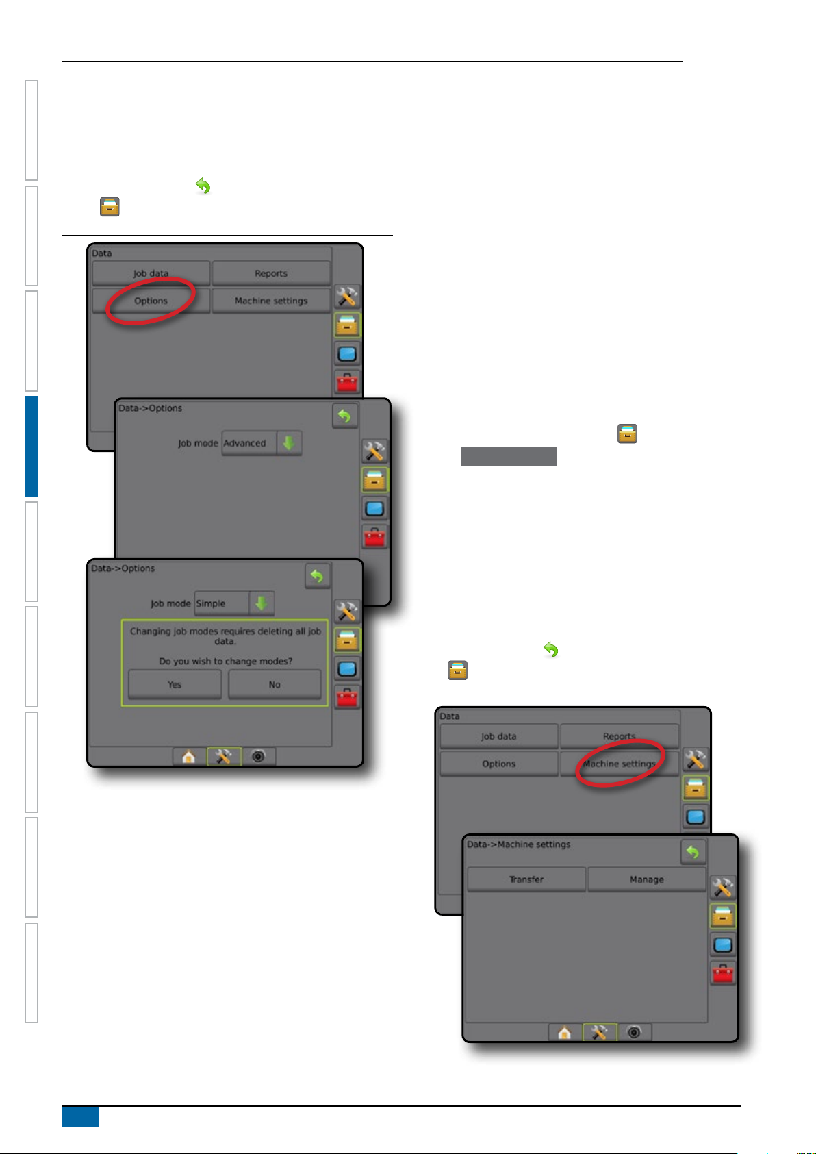
MATRIX® Pro 570GS • MATRIX® Pro 840GS
5. "Changing job modes requires deleting all job data. Do you
wish to change modes?"
Press:
►Yes – to make the change
►No – to keep the current setting
6. Press RETURN arrow or DATA MANAGEMENT side
HOME GUIDANCEFULL SCREEN IMPLEMENTINTRODUC TION GNSS RATE CONTROL APPENDIXSETUP
tab to return to the main Data Management screen.
Figure 4-36: Options – change job mode
Machine settings
The Machine settings menu is used to create and manage
individual Machine proles representing the conguration of the
console on a particular vehicle/equipment setup. Each Machine
Prole records the settings in use at the time the prole is
generated allowing the customer to recall their exact setup for later
use. Machine proles can be used to transfer settings to another
console of the same make and model with the same attached
hardware.
Machine settings include:
• Implement settings
• AutoSteer/Tilt Correction settings
• Rate Control settings
• Job-specic settings (including application rates, application
type, and Product Channel assignments)
NOTE: Not all settings are saved as part of the machine settings.
See the appendix "Matrix Pro GS Console Menu Settings"
for details.
1. Press DATA MANAGEMENT side tab .
2. Press Machine Settings .
3. Select from:
►Transfer – allows the transfer of selected machine settings
to or from a USB drive, as well as deleting machine settings
►Manage – allows the creation of a new empty machine
settings, the copying of a selected machine settings to a
new machine settings, the deletion of a selected machine
settings, the saving of the current machine settings to the
selected machine settings, or the loading of the selected
machine settings to the current settings
4. Press RETURN arrow or DATA MANAGEMENT side
tab to return to the main Data Management screen.
Figure 4-37: Machine settings
28
www.teejet.com
Page 37

MATRIX® Pro 570GS • MATRIX® Pro840GS
Transfer
The machine settings transfer screen allows the transfer of
selected machine settings to or from a USB drive, as well as
deleting machine settings.
Machine settings transferred to a USB storage device can be
opened and updated using Fieldware Link. From Fieldware Link,
machine settings can be ported back to a USB storage device to
be moved back onto the console internal storage for use.
NOTE: Not all settings saved as part of the machine settings are
available to be edited in Fieldware Link. See the appendix
"Matrix Pro GS Console Menu Settings" for details.
Machine settings transferred to a storage device
are removed from the console and are no longer
available for use.
1. Press DATA MANAGEMENT side tab .
2. Press Machine Settings .
3. Press Transfer .
4. Select from:
►Move Machine settings to USB Storage – used to move
machine settings from internal storage to USB
►Move Machine settings to Internal Storage
move machine settings from USB to internal storage
►Delete Machine settings – used to delete machine
settings from internal storage or USB storage
5. Press RETURN arrow
tab to return to the main Data Management screen.
Figure 4-38: Machine settings – transfer
or DATA MANAGEMENT side
– used to
Manage
The Machine settings manage screen allows the creation of a
new empty machine settings, the copying of a selected machine
settings to a new machine settings, the deletion of a selected
machine settings, the saving of the current machine settings to the
selected machine settings, or the loading of the selected machine
settings to the current settings.
NOTE: Not all settings are saved as part of the machine settings.
See the appendix "Matrix Pro GS Console Menu Settings"
for details.
1. Press DATA MANAGEMENT side tab .
2. Press Machine Settings .
3. Press Manage .
4. Select from:
►New – used to create a new machine setting with no
associated implement information
►Copy – used to copy a selected machine settings into a new
machine settings
►Delete – used to delete a selected machine settings from
internal storage
►Save – used to save the current machine settings to the
selected machine settings
►Load – used to load the selected machine settings to the
current settings
5. Press RETURN arrow or DATA MANAGEMENT side
tab to return to the main Data Management screen.
Figure 4-39: Machine settings – manage
HOMEGUIDANCE FULL SCREENIMPLEMENT INTRODUCTIONGNSSRATE CONTROLAPPENDIX SETUP
98- 05273-EN R7
29
Page 38

MATRIX® Pro 570GS • MATRIX® Pro 840GS
Copy machine prole
The copy machine prole option is used to duplicate the selected
machine prole for recall of that prole at a later use. Machine
proles can be used to transfer settings to another console of the
same make and model with the same attached hardware.
1. Press DATA MANAGEMENT side tab .
2. Press Machine settings .
HOME GUIDANCEFULL SCREEN IMPLEMENTINTRODUC TION GNSS RATE CONTROL APPENDIXSETUP
3. Press Manage .
4. Select the machine prole to be copied into a new prole.
5. Press Copy .
6. Name the new prole.
7. Press the ACCEPT icon to save the new prole or the
CANCEL icon to leave the keyboard without saving.
8. Press RETURN arrow or DATA MANAGEMENT side
tab to return to the main Data management screen
Figure 4-40: Machine settings – copy profile
CONSOLE
Console Setup is used to congure the display and cultural
settings, unlock advanced features and play back demo GNSS
data. Information about other devices attached to the system can
be found in the About section.
1. Press SYSTEM SETUP bottom tab .
2. Press CONSOLE side tab .
3. Select from:
►About – used to display the system software version as well
as the software versions of modules connected to the CAN
bus
►Display – used to congure colour scheme and LCD
brightness, establish screenshot availability, and calibrate
the touchscreen
►Cultural – used to congure units, language, and time zone
settings
►Audio Volume – used to adjust the volume level of the audio
speaker
►Demo GNSS – used to start playback of simulated GNSS
data
►Feature Unlock – used to unlock advanced features
Figure 4-41: Console options
New machine settings name
1 5 92 6 03 74 8
q
Caps
Alt
w
e
a
s
z
t
r
d
x
y
f
g
v
c
u
h
b
n
<---
o
i
k
j
Shift
m
p
l
30
www.teejet.com
Page 39

MATRIX® Pro 570GS • MATRIX® Pro840GS
About
About/Save screen displays the system software version as well
as the software versions of modules connected to the CAN bus.
To aid when troubleshooting problems in the eld, an end user
can use the Save button to download a text le containing current
software information to a USB drive, then e-mail the le to support
personnel.
1. Press CONSOLE side tab .
2. Press
3. Select from:
4. Press RETURN arrow or CONSOLE side tab to
NOTE: The Save option is not available for selection (greyed
Figure 4-42: About options
About .
►View information including unit serial number, software
version, and connected modules
►With a USB drive in the console, press
the About information to the USB drive. Saved version
information to USB drive will conrm the save.
return to the main Console Settings screen.
out) until a USB drive is inserted properly.
Save to save
Display
Display is used to congure colour scheme and LCD brightness,
establish screenshot availability and calibrate the touchscreen.
1. Press CONSOLE side tab .
2. Press
3. Select from:
4. Press RETURN arrow
Figure 4-43: Display Options
Display .
►Colour scheme – used to choose the colour scheme that is
easiest to read
►LCD brightness – used to adjust the brightness of the
console display
►Screenshot – used to allow screen captures to be saved to
a USB drive
►Screen calibration – used to calibrate the touch screen
or CONSOLE side tab to
return to the main console Settings screen.
HOMEGUIDANCE FULL SCREENIMPLEMENT INTRODUCTIONGNSSRATE CONTROLAPPENDIX SETUP
98- 05273-EN R7
31
Page 40

MATRIX® Pro 570GS • MATRIX® Pro 840GS
Cultural
Cultural is used to congure units, language, and time zone
settings.
1. Press CONSOLE side tab .
2. Press
3. Select from:
HOME GUIDANCEFULL SCREEN IMPLEMENTINTRODUC TION GNSS RATE CONTROL APPENDIXSETUP
4. Press RETURN arrow or CONSOLE side tab to
Figure 4-44: Cultural options
Cultural .
►Units – used to dene the system units
►Language – used to dene the system language
►Time zone – used to establish the local time zone
return to the main Console Settings screen.
Audio volume
Audio volume adjusts the volume level of the audio speaker.
1. Press CONSOLE side tab .
2. Press Audio Volume .
3. Press:
►UP arrow to increase the sound
►DOWN arrow to soften the sound
4. Press RETURN arrow or CONSOLE side tab to
return to the main Console Settings screen.
Figure 4-45: Audio volume options
32
www.teejet.com
Page 41

MATRIX® Pro 570GS • MATRIX® Pro840GS
Demo GNSS
Demo GNSS is used to start the playback of a simulated GNSS
signal.
WARNING! This tool will disable incoming GNSS positions and
begin playing back simulated data. A console reboot is
necessary in order to restore real GNSS.
1. Press CONSOLE side tab .
2. Press
3. Press
4. Press RETURN arrow or CONSOLE side tab to
NOTE: A console reboot is necessary in order to restore a real
Figure 4-46: Demo GNSS
Demo GNSS .
Start .
return to the main Console Settings screen.
GNSS.
Restart Demo GNSS
Demonstration GNSS can be restarted.
1. Press CONSOLE side tab .
2. Press
3. Press
4. Press RETURN arrow
Figure 4-47: Restart Demo GNSS
Demo GNSS .
Restart .
or CONSOLE side tab to
return to the main Console Settings screen.
Feature unlock
Feature Unlock is used to unlock advanced features.
HOMEGUIDANCE FULL SCREENIMPLEMENT INTRODUCTIONGNSSRATE CONTROLAPPENDIX SETUP
NOTE: The unlock code is unique for each console. Contact
TeeJet Technologies Customer Service. Once unlocked, a
feature remains unlocked unless the console is fully reset.
1. Press CONSOLE side tab .
2. Press Feature Unlock .
3. Press the locked feature button . for the locked feature:
►BoomPilot for spreader – allows for spreader application
options when used with a compatible spreader implement
►FieldPilot Pro / UniPilot Pro – allows for AutoSteer options
when using a SCM Pro
►Third-party rate control – allows for rate control options
when used with a compatible third-party rate controller
4. Enter unlock code if required.
5. Restart the console.
98- 05273-EN R7
33
Page 42

MATRIX® Pro 570GS • MATRIX® Pro 840GS
Figure 4-48: Feature Unlocked
HOME GUIDANCEFULL SCREEN IMPLEMENTINTRODUC TION GNSS RATE CONTROL APPENDIXSETUP
1
Enter unlock code
2
3
4
5
TOOLS
Tools is used to upload software updates for system devices,
and to do various calculations on a regular calculator or a unit
converter.
1. Press SYSTEM SETUP bottom tab .
2. Press TOOLS side tab .
3. Select from:
►Upload software – used to upload software updates from a
USB drive for system devices.
►Extras – accesses Calculator and Units converter
Figure 4-49: Tools options
Clear
6
7
8
9
0
<--
A
B
C
D
E
F
Upload software
Unlock successful!
The BoomPilot for Spreader feature
is now unlocked. Please reboot
console to begin using BoomPilot for
Spreader.
The Upload software screen is used to upload software updates
from a USB drive for system devices.
NOTE: Availability of this feature will vary depending on software
version.
1. Press TOOLS side tab .
2. Press Upload Software .
3. Insert the USB drive containing software updates into the
console.
4. Press Device DOWN arrow and select the device for which
software will be updated:
5. Press Software DOWN arrow and select the software
update to be uploaded to the device.
6. Press Begin Upload .
7. When prompted, press OK .
8. Press RETURN arrow to return to the Tools screen, or
press CONSOLE side tab to return to the main console
Settings screen.
34
www.teejet.com
Page 43

MATRIX® Pro 570GS • MATRIX® Pro840GS
Figure 4-50: Upload software
Figure 4-51: Calculator
Backspace
MC
MR
7
4
HOMEGUIDANCE FULL SCREENIMPLEMENT INTRODUCTIONGNSSRATE CONTROLAPPENDIX SETUP
0
Clear
8
9
5
6
Clear all
/
*
√
2
x
Extras
1. Press TOOLS side tab .
2. Press
3. Select from:
Extras .
►Calculator – used to perform mathematical calculations
►Units converter – used to perform unit conversions for area,
length, volume, pressure, mass, temperature, or angle
MS
M+
1
0
Figure 4-52: Units converter
2
3
.
±
-
1/x
+
=
98- 05273-EN R7
35
Page 44

MATRIX® Pro 570GS • MATRIX® Pro 840GS
CHAPTER 5 GNSS RECEIVER CONFIGURATION
GNSS receiver conguration is used to congure GNSS Type, GNSS Port, and PRN, and other GNSS parameters, and to view GNSS
status information.
HOME SETUP GUIDANCEFULL SCREEN IMPLEMENTINTRODUCTION RATE CONTROL APPENDIXGNSS
GNSS receiver conguration
NOTE: These settings are required for rate control, assisted/
auto steering, and tilt sensor operation, as well as proper
implement operation.
1. Press CONFIGURATION side tab .
2. Press
3. Select from:
4. Press RETURN arrow
GNSS Receiver Conguration .
►GNSS type – sets to accept GNSS source transmissions:
GPS, GLONASS, or SBAS (with or without DGPS required).
►GNSS port – sets GNSS communication port: internal or
external
►GNSS status information – displays current baud rate, baud
rate status, GNSS status information: GGA/VTG (data
rates), number of satellites, HDOP, PRN, GGA quality,
receiver, receiver version, UTM zone, and correction model
►Programme – allows direct programming of the GNSS
receiver through a command line interface. Only TeeJet
support technicians should use this feature. Use at your
own risk!
►PRN – selects the rst of two possible SBAS PRN's to
provide SBAS correction data.
►Alternate PRN – allows possible selection of a second
SBAS PRN to provide correction data
►Show refresh GNSS position button – establishes if the
refresh GNSS position button is available on the guidance
screens
or CONFIGURATION side tab
to return to the main Conguration screen.
Figure 5-1: GNSS options
GNSS type
This menu allows the user to specify the requirements of the
GGA data received by the application software based on the
GGA Quality Indicator data eld. These selections dictate the
commands sent to program the internal receiver for use.
• GPS – uncorrected signals from the GPS system
• GLONASS – uncorrected signals from the GLONASS system
• SBAS (e.g. EGNOS, GAGAN, MSAS, SDCM, WAAS) –
differentially corrected signals from the SBAS system
• DGPS required – differentially corrected GPS signals
36
1. Press NEXT PAGE arrow to access the list of options.
2. Select:
►GPS – single point uncorrected position data based on GPS
only with a GGA QI of "1" is accepted.
NOTE: GPS is always selected.
►GPS+GLONASS – single point uncorrected position data
based on GPS and GLONASS with a GGA QI of "1" is
accepted.
►GPS+SBAS – either single point uncorrected or SBAS
corrected position data are accepted - GGA QI of "1" or "2"
(3, 4 or 5 are also accepted).
►GPS+GLONASS+SBAS – either single point uncorrected or
SBAS corrected position data are accepted - GGA QI of "1"
or "2" (3, 4 or 5 are also accepted).
www.teejet.com
Page 45

MATRIX® Pro 570GS • MATRIX® Pro840GS
►GPS+GLONASS+SBAS+DGPS – only GGA data with a
QI value of "2" or higher is accepted (3, 4 or 5 are also
accepted).
NOTE: All console based mapping, application and
guidance functions are ceased if the GGA QI value drops
below "2" with this setting checked.
3. Exit this screen to begin initializing the GNSS receiver. This
takes about a minute, and the console will not respond until
complete.
Figure 5-2: GNSS type
GNSS port
The COM port can be set to “Internal” to use the internal GNSS
receiver and transmit out, or “External” to receive external GNSS
data.
1. Press DOWN arrow to access the list of options.
2. Select:
►Internal – uses position data from the internal GNSS
receiver; these NMEA data are sent out the RS-232 serial
"Port A" of the Matrix harness at 115,200 baud
►External – uses position data from an externally attached
GNSS receiver attached to the RS-232 serial "Port A" of the
Matrix harness
NOTE: An external receiver is required to work with TerraStar,
OmniStar HP/XP, or RTK position data.
Figure 5-3: GNSS port
External receiver minimum conguration requirements
Before the Matrix Pro GS will connect and work with an external
GNSS receiver, these minimum conguration requirements must be
met.
Serial Port Settings
Baud rate: not allowed below 38,400
Recommended
FieldPilot Pro /
UniPilot Pro
Data bits: 8
Parity: None
Stop bits: 1
Serial port connection requirements
Male 9-pin RS-232 serial cable
NOTE: May require Null modem adapter depending on pin-
out of receiver.
NMEA strings
GGA 10.0 Hz
Optional VTG 10.0 Hz
ZDA 1.0 Hz
38,400, 56,000, 57,600,
76,800, or 115,200
115,200
HOMESETUPGUIDANCE FULL SCREENIMPLEMENT INTRODUCTIONRATE CONTROLAPPENDIX GNSS
98- 05273-EN R7
37
Page 46

MATRIX® Pro 570GS • MATRIX® Pro 840GS
GNSS status information
GNSS status information displays a snapshot of the current GNSS
status information.
1. Press View Status .
2. View data including:
◄Baud rate – the current status of the GNSS
HOME SETUP GUIDANCEFULL SCREEN IMPLEMENTINTRODUCTION RATE CONTROL APPENDIXGNSS
◄Baud rate status – the rate at which information is
transferred/ communicated.
NOTE: a minimal baud rate maybe required for some
software version to work at their peak performance.
◄GGA/VTG/TCP data rates – the number of GNSS positions
per second.
◄Number of satellites – the number of GNSS satellites in
view (minimum of 4 are required for DGPS)
◄HDOP – a measure of satellite geometry strength in the
horizontal plane. A HDOP value of less than 2 is preferred.
◄PRN – the current DGPS satellite ID
◄GGA quality – the current quality indicator of the GNSS
signal (see GGA requirements chart)
◄Receiver – the current indicator of the receiver
◄Receiver version – the software version installed on the
receiver
◄UTM zone – zone where currently located (see "UTM
coordinates and zones" in this manual)
◄Model – the correction models available to be used with the
current receiver conguration
3. Press
OK to return to the GNSS receiver conguration
screen.
NOTE: If GNSS is not available, all entries will be “Invalid”.
Figure 5-4: GNSS status information
GNSS status information on guidance screens
GNSS status displays information regarding current GNSS status,
including data rates, number of satellites in view, HDOP and PRN
status, receiver and version, satellite quality and ID, and UTM
zone.
1. Press GNSS STATUS icon :
Figure 5-5: Guidance screen GNSS status information
27.00
ha
Status: Good GNSS
Baud rate: 115200
GGA rate: 10 Hz
VTG rate: 10 Hz
TCP rate: 10 HZ
Number of satellites: 8
HDOP: 1
PRN: 138
GGA quality: 2
Receiver: 7
Receiver version: 010201
UTM zone: 11
Model: LXGMTS
Mark A
10.0
km/h
GGA Requirements
GGA Quality required to be able to work with various types of
signal can vary. See table below for requirements.
Service Indicator Accuracy
GPS/GLONASS only 1 <10 m
WAAS/EGNOS 2 <1.5 m
RTK 4 or 5 4 cm
OmniSTAR HP/XP 5 10 cm
Glide/ClearPath* 9 <1 m
TerraStar C (converged) 5 10 cm
*For a 60 minute period.
38
www.teejet.com
Page 47

MATRIX® Pro 570GS • MATRIX® Pro840GS
Programme
Programme allows direct programming of the GNSS receiver a
command line interface. Only TeeJet support technicians should
use this feature. Use at your own risk!
1. Press Start .
2. Adjust programming as required.
Figure 5-6: Programming receiver
Alternate PRN
When PRN is not automatic, allows possible selection of a second
SBAS PRN to provide correction data.
1. Press DOWN arrow to access the list of options.
2. Select:
►None – no alternate PRN number
►Number – contact your local dealer for the number
associated with your operating location
Figure 5-8: Alternate PRN
HOMESETUPGUIDANCE FULL SCREENIMPLEMENT INTRODUCTIONRATE CONTROLAPPENDIX GNSS
PRN
The PRN menu allows selection of up to two specic SBAS
satellites to use for SBAS corrections. This allows the user to
remove SBAS correction data from malfunctioning SBAS satellites.
1. Press DOWN arrow to access the list of options.
2. Select:
►Automatic – automatic PRN selection
►Number – contact your local dealer for the number
associated with your operating location
Figure 5-7: PRN
PRN not shown
PRN options are only available with SBAS GNSS Type selected.
Figure 5-9: PRN not shown
98- 05273-EN R7
39
Page 48

MATRIX® Pro 570GS • MATRIX® Pro 840GS
Show refresh GNSS position button
Show refresh GNSS position button establishes if the refresh
GNSS position button is available on the guidance screens.
The refresh GNSS position button will reset the ClearPath lter
in the OEMStar receiver in cases where the user has had the
receiver running in close proximity to heavy tree cover and/or
buildings.
HOME SETUP GUIDANCEFULL SCREEN IMPLEMENTINTRODUCTION RATE CONTROL APPENDIXGNSS
NOTE: Activating the refresh while in a job will cause a
momentary interruption in the relay of GNSS data. This
will most likely result in sections already on in automatic
BoomPilot mode to go off for a short period of time.
The refresh should not be done during active application.
Figure 5-10: Refresh GNSS position button
GNSS glossary
Commercial satellite provider:
Another common source for DGPS signals. Error correction
information obtained from their base stations is sent to a
communications satellite (separate from the GPS satellites) and
broadcast to the user. These satellite-based corrections tend to
have more widespread coverage than tower-based broadcasts
(FM links), and system accuracy is not greatly affected by the
user’s distance from the base station receivers. Most of these
service providers require a subscription fee for use. A commonly
known provider is OmniSTAR.
CORS (continuously operating reference
station)/Network RTK:
A series of base stations spread across a given geographic
region (such as an entire state/county) that are networked via a
centralized computer and which broadcast RTK correction data
over the Internet. CORS networks may be publicly or privately
owned/operated and may offer a free signal or require an annual
subscription fee. By accessing a CORS network via a cellular
connection, the end-user eliminates the need to own a base
station.
0.00
ha
Mark A
0.0
km/h
Differential corrections
Differential Corrections is a solution specic to the "doubledifferencing" algorithm used to determine the correction values
applied by RTK to each GNSS satellites range data. "Corrections"
is the generic term applied to all forms of potential corrections from
SBAS (WAAS/EGNOS) through to OmniStar, TerraStar PPP and
RTK.
Differential GPS (DGPS):
Use of the specic RTK solution to apply differential corrections to
the GPS satellite constellation data.
EGNOS (European geostationary navigation
overlay service):
A satellite based augmentation system (SBAS) developed jointly
by the European space agency (ESA), European community
and EUROCONTROL. The system is free to use and provides
differential correction coverage primarily across the European
continent. EGNOS delivers pass-to-pass accuracies of 15-25 cm
and year-to-year accuracies of +/-1 m.
GLONASS (Global navigation satellite system):
A global satellite navigation system developed and operated by
the Russian government. It is composed of approximately 24
satellites which continuously orbit the earth. While early GNSS
receivers typically utilized only GPS signals, many of today’s
GNSS receivers can utilize signals from both GPS and GLONASS,
effectively increasing the total number of satellites available for
use.
40
www.teejet.com
Page 49

MATRIX® Pro 570GS • MATRIX® Pro840GS
GNSS Precise point positioning (PPP)
PPP is a subscription based globally provided satellite correction
service broadcast to properly equipped GNSS receivers. PPP
utilizes a global array of reference stations to correct for satellite
clock and orbit errors which are then broadcast to local receivers.
PPP does require a convergence time.
GNSS (Global navigation satellite system):
A general term that refers to a multiple satellite navigation system
used by a receiver to compute its position. Examples of these
systems include: GPS developed by the United States and
GLONASS by Russia. Additional systems in development include
Galileo by the European Union and Compass by China. New
generation GNSS receivers are being designed to utilize multiple
GNSS signals (such as GPS and GLONASS). Depending on
constellation and desired accuracy levels, system performance
may be improved by having access to a greater number of
satellites.
GPS (Global positioning system):
The name of the satellite-navigation network maintained by the
U.S. Department of Defense. It is composed of approximately 30
satellites which continuously orbit the earth. The term is also used
to refer to any device that depends on navigation satellites for
functionality.
SBAS (Satellite based augmentation system):
A general term that refers to any satellite-based differential
correction system. Examples of SBAS include: WAAS in the
United States, EGNOS in Europe and MSAS in Japan. Additional
SBAS covering other regions of the world will likely be coming
online in the future.
WAAS (Wide-area augmentation system):
A satellite correction service developed by the Federal Aviation
Administration (FAA). It is free to use and provides coverage
across the U.S. along with parts of Canada and Mexico. WAAS
delivers pass-to-pass accuracies of 15-25 cm; however, year-to-
year accuracy will be in the range of +/-1 m.
HOMESETUPGUIDANCE FULL SCREENIMPLEMENT INTRODUCTIONRATE CONTROLAPPENDIX GNSS
NTRIP (Networked transportation of RTCM via
internet protocol):
An internet-based application that makes the RTCM correction
data from the CORS stations available to anyone with an internet
connection and the appropriate log-on credentials to the NTRIP
server. Typically uses a cellular link to get to the internet and the
NTRIP server.
Positional drift
The constant change in the GNSS position calculation primarily
caused by atmospheric and ionospheric changes, poor satellite
geometry (possibly caused by obstructions such as buildings and
trees, satellite clock errors and satellite constellation changes. For
sub-decimeter accuracy dual frequency receivers using either PPP
or RTK solutions are recommended.
RTK (Real time kinematic):
Currently the most accurate GPS correction system available that
uses a land-based reference station located in relatively close
proximity to the GPS receiver. RTK can provide one-inch, also
known as centimeter, pass-to-pass accuracy and also provides
year-to-year position stability. RTK users can have their own base
stations, subscribe to RTK Networks or use CORS.
98- 05273-EN R7
41
Page 50

MATRIX® Pro 570GS • MATRIX® Pro 840GS
CHAPTER 6 IMPLEMENT SETUP
Implement Setup is used to establish the various settings associated with straight mode, spreader mode, and staggered mode.
HOME SETUP GUIDANCEFULL SCREENINTRODUCTION GNSS RATE CONTROL APPENDIXIMPLEMENT
Settings will vary depending on if there is section control available: SmartCable, Section Driver Module (SDM), or Switch Function
Module (SFM).
IMPLEMENT TYPE
Implement Type selects the type of application pattern that most
closely represents your system.
● In straight mode – the boom sections have no length and
are on a line a xed distance from the antenna
● In spreader mode – a virtual line is created in line with the
delivery disks from which the application section or sections
can vary in length and can be at different distances from the
line (availability depends on the specic equipment in the
system)
● In staggered mode – a virtual line is created in line with
Section 1 from which the application section or sections
have no length and can be at different distances from the
line (availability depends on the specic equipment in the
system)
Section numbers
Sections are numbered from left to right while facing in the
machine's forward direction.
Figure 6-1: Implement type – straight
5 4 3 2 1
Figure 6-2: Implement type – spreader
4
5
6
7
3
2
1
42
www.teejet.com
Figure 6-3: Implement type – staggered
4 3 2
5
1
Page 51

MATRIX® Pro 570GS • MATRIX® Pro840GS
Straight
The boom sections have no length and are on a line a xed
distance from the antenna.
Single section
No section control is available on the system.
1. Select Straight implement type on Implement screen.
2. Press Implement Type NEXT PAGE arrow
3. Select from:
►Implement in-line offset direction
the implement is located in front of (forward) or behind
(backward) the GNSS antenna while facing in the vehicle's
forward direction
►Implement in-line offset distance – measured in parallel
to the centerline of the vehicle, denes the in-line distance
from the GNSS antenna to the implement in decimal meters
►Implement lateral offset direction – denes the lateral
direction, either left or right, from the centerline of the
machine to the center of the implement while facing in the
machine's forward direction
►Implement lateral offset distance – denes the lateral
distance from the centerline of the machine to the center of
the implement in decimal meters
4. Press RETURN arrow to return to the Implement screen
or CONFIGURATION side tab to return to the main
Conguration screen.
Figure 6-4: Single section
– establishes if
.
Figure 6-5: Offset Directions and Distances
HOMESETUPGUIDANCE FULL SCREEN INTRODUCTIONGNSSRATE CONTROLAPPENDIX IMPLEMENT
Multiple sections
Section control is available (SmartCable, Section driver module
(SDM), or Switch function module (SFM).
1. Select Straight implement type on Implement screen.
2. Press Implement Type NEXT PAGE arrow .
3. Select from:
►Implement in-line offset direction – establishes if
the implement is located in front of (forward) or behind
(backward) the GNSS antenna while facing in the vehicle's
forward direction
►Implement in-line offset distance – measured in parallel
to the centerline of the vehicle, denes the in-line distance
from the GNSS antenna to the implement in decimal meters
►Implement lateral offset direction – denes the lateral
direction, either left or right, from the centerline of the
machine to the center of the implement while facing in the
machine's forward direction
►Implement lateral offset distance – denes the lateral
distance from the centerline of the machine to the center of
the implement in decimal meters
►Overlap – used to dene the amount of overlap allowed
when using automatic boom section control
►Delay on time – used to set the time when the section will
switch on when entering an area that has not been applied
NOTE: If the application turns on too soon when entering
an unapplied area, decrease the Delay on time. If the
application turns on too late, increase the Delay on time.
►Delay off time – used to set the time when the section will
switch off when entering an area that has been applied
NOTE: If the application turns off too soon when entering
an unapplied area, decrease the Delay off time. If the
application turns off too late, increase the Delay off time.
4. Press RETURN arrow to return to the Implement screen
or CONFIGURATION side tab to return to the main
Conguration screen.
98- 05273-EN R7
43
Page 52

MATRIX® Pro 570GS • MATRIX® Pro 840GS
Figure 6-6: Multiple Sections
HOME SETUP GUIDANCEFULL SCREENINTRODUCTION GNSS RATE CONTROL APPENDIXIMPLEMENT
Figure 6-8: Overlap
100%50%0%
Figure 6-7: Offset Directions and Distances
Spreader – TeeJet
A virtual line is created in line with the delivery disks from which
the application section or sections can vary in length and can be at
different distances from the line (availability depends on the specic
equipment in the system).
Single section
No section control is available on the system.
1. Select Spreader implement type on Implement screen.
2. Press Implement Type NEXT PAGE arrow .
3. Select from:
►Setup type – used to select TeeJet spreader type
►Antenna to Disks Distance – used to dene the
distance from the GNSS antenna to the disks or dispersal
mechanism
►Implement lateral offset direction – denes the lateral
direction, either left or right, from the centerline of the
machine to the center of the implement while facing in the
machine's forward direction
►Implement lateral offset distance – denes the lateral
distance from the centerline of the machine to the center of
the implement in decimal meters
►Spread Offset Distance – used to set the distance
between the disks or dispersal mechanism and where
product initially hits the ground for the section
►Spread length – used to set the length of application for
the section
4. Press RETURN arrow to return to the Implement screen
or CONFIGURATION side tab to return to the main
Conguration screen.
44
www.teejet.com
Page 53

MATRIX® Pro 570GS • MATRIX® Pro840GS
Figure 6-9: Single section
Figure 6-10: Distances and length
Multiple sections
Section control is available (SmartCable, Section driver module
(SDM), or Switch function module (SFM).
1. Select Spreader implement type on Implement screen.
2. Press Implement type NEXT PAGE arrow .
3. Select from:
►Setup type – used to select
►Antenna to Disks distance
distance from the GNSS antenna to the disks or dispersal
mechanism
►Implement Lateral offset direction
direction, either left or right, from the centerline of the
machine to the center of the implement while facing in the
machine's forward direction
►Implement lateral offset distance
distance from the centerline of the machine to the center of
the implement in decimal meters
►Overlap – used to dene the amount of overlap allowed
when using automatic boom section control
►Delay on time – used to set the time when the section will
switch on when entering an area that has not been applied
NOTE: If the application turns on too soon when entering
an unapplied area, decrease the Delay on time. If the
application turns on too late, increase the Delay on time.
TeeJet spreader type
– used to dene the
– denes the lateral
– denes the lateral
HOMESETUPGUIDANCE FULL SCREEN INTRODUCTIONGNSSRATE CONTROLAPPENDIX IMPLEMENT
Figure 6-11: Lateral Offset Direction and Distance
►Delay off time – used to set the time when the section will
switch off when entering an area that has been applied
NOTE: If the application turns off too soon when entering
an unapplied area, decrease the Delay off time. If the
application turns off too late, increase the Delay off time.
►Spread offset distance – used to set the distance
between the disks or dispersal mechanism and where
product initially hits the ground on Section 1.
►Section offsets – used to set the offset distance from
Section 1 (the Spread Offset line) to the leading edge of
each section. Section 1 is always 0. All other sections can
be different distances.
►Section lengths
each section. Each section can be a different length.
NOTE: Sections are numbered from left to right while
facing in the machine's forward direction.
4. Press RETURN arrow
or CONFIGURATION side tab to return to the main
Conguration screen.
– used to set the length of application in
to return to the Implement screen
98- 05273-EN R7
45
Page 54

MATRIX® Pro 570GS • MATRIX® Pro 840GS
Figure 6-12: Multiple sections
HOME SETUP GUIDANCEFULL SCREENINTRODUCTION GNSS RATE CONTROL APPENDIXIMPLEMENT
Figure 6-14: Lateral offset direction and distance
Figure 6-15: Overlap
Figure 6-13: Distances and length
46
www.teejet.com
100%50%0%
Page 55

MATRIX® Pro 570GS • MATRIX® Pro840GS
Spreader – OEM
A virtual line is created in line with the delivery disks from which
the application section or sections can vary in length and can be at
different distances from the line.
Single section
No section control is available on the system.
1. Select Spreader implement type on Implement screen.
2. Press Implement type NEXT PAGE arrow
3. Select from:
►Setup type – used to select
►Antenna to Disks Distance – used to dene the distance
from the GNSS antenna to the disks or dispersal
mechanism
►Implement lateral offset direction – denes the lateral
direction, either left or right, from the centerline of the
machine to the center of the implement while facing in the
machine's forward direction
►Implement lateral offset distance – denes the lateral
distance from the centerline of the machine to the center of
the implement in decimal meters
►Start distance – used to set the start distance when exiting
an applied area (consult spreader manufacturer for value)
►Stop distance – used to set the stop distance when entering
an applied area (consult spreader manufacturer for value)
NOTE: Consult spreader manufacturer for start and stop
distances.
4. Press RETURN arrow to return to the Implement screen
or CONFIGURATION side tab to return to the main
Conguration screen.
Figure 6-16: Single section
OEM spreader type
.
Multiple sections
Section control is available (SmartCable, Section driver module
(SDM), or Switch function module (SFM).
1. Select Spreader implement type on Implement screen.
2. Press Implement type NEXT PAGE arrow .
3. Select from:
►Setup type – used to select
►Antenna to disks distance – used to dene the distance
from the GNSS antenna to the disks or dispersal
mechanism
►Implement lateral offset direction – denes the lateral
direction, either left or right, from the centerline of the
machine to the center of the implement while facing in the
machine's forward direction
►Implement lateral offset distance – denes the lateral
distance from the centerline of the machine to the center of
the implement in decimal meters
►Start distance – used to set the start distance when exiting
an applied area (consult spreader manufacturer for value)
►Stop distance – used to set the stop distance when entering
an applied area (consult spreader manufacturer for value)
NOTE: Consult spreader manufacturer for start and stop
distances.
►Section start offsets – used to set the offset distance from
Section 1 to the leading edge of each section. Section 1 is
always 0. All other sections can be different distances.
►Section stop offsets – used to set the offset distance from
Section 1 to the trailing edge of each section. Each section
can be a different distance.
NOTE: Consult spreader manufacturer for section start
and stop offset values. Sections are numbered from left to
right while facing in the machine's forward direction.
OEM spreader type
HOMESETUPGUIDANCE FULL SCREEN INTRODUCTIONGNSSRATE CONTROLAPPENDIX IMPLEMENT
4. Press RETURN arrow
or CONFIGURATION side tab to return to the main
Conguration screen.
to return to the Implement screen
98- 05273-EN R7
47
Page 56

MATRIX® Pro 570GS • MATRIX® Pro 840GS
Figure 6-17: Multiple sections
HOME SETUP GUIDANCEFULL SCREENINTRODUCTION GNSS RATE CONTROL APPENDIXIMPLEMENT
Staggered
A virtual line is created in line with Section 1 from which the
application section or sections have no length and can be at
different distances from the line.
Multiple sections
Section control is available (SmartCable, Section driver module
(SDM), or Switch function module (SFM).
1. Select Staggered implement type on Implement screen.
2. Press Implement type NEXT PAGE arrow
3. Select from:
►In-line section 1 offset direction
Section 1 (the zero-point of the Section Offsets) is located
in front of or behind the GNSS antenna as the vehicle
moves in a forward direction
►In-line section 1 offset distance – used to dene the
in-line distance from the GNSS antenna to Section 1 (the
zero-point of the Section Offsets)
►Implement lateral offset direction – denes the lateral
direction, either left or right, from the centerline of the
machine to the center of the implement while facing in the
machine's forward direction
►Implement lateral offset distance – denes the lateral
distance from the centerline of the machine to the center of
the implement in decimal meters
►Overlap – used to dene the amount of overlap allowed
when using automatic boom section control
►Delay on time – used to set the time when the section will
switch on when entering an area that has not been applied
NOTE: If the application turns on too soon when entering
an unapplied area, decrease the Delay on time. If the
application turns on too late, increase the Delay on time.
– used to select whether
.
48
►Delay off time – used to set the time when the section will
switch off when entering an area that has been applied
NOTE: If the application turns off too soon when entering
an unapplied area, decrease the Delay off time. If the
application turns off too late, increase the Delay off time.
►Section offsets – used to set the offset distance from
Section 1 (the In-line Section 1 offset distance line) to each
section. A positive offset value will move the section behind
Section 1. A negative offset value will move the section in
front of Section 1. Section 1 is always 0. All other sections
can be different distances.
4. Press RETURN arrow to return to the Implement screen
or CONFIGURATION side tab to return to the main
Conguration screen.
www.teejet.com
Page 57

MATRIX® Pro 570GS • MATRIX® Pro840GS
Figure 6-18: Multiple sections
Figure 6-20: Offset directions and distances – in front of section 1
HOMESETUPGUIDANCE FULL SCREEN INTRODUCTIONGNSSRATE CONTROLAPPENDIX IMPLEMENT
Figure 6-21: Overlap
Figure 6-19: Offset directions and distances – behind section 1
100%50%0%
98- 05273-EN R7
49
Page 58

MATRIX® Pro 570GS • MATRIX® Pro 840GS
APPLICATION OR WORKING WIDTH
Application width [Straight implement type or Staggered implement type] or Working width [Spreader implement type] is used to enter the
width of the single section or width of each section to calculate the total width of the implement.
Single section
No section control is available on the system.
HOME SETUP GUIDANCEFULL SCREENINTRODUCTION GNSS RATE CONTROL APPENDIXIMPLEMENT
Application width or Working width is used to enter the total
width of the single section of the implement. Range is 1.0 to
75.0 metres.
1. Press CONFIGURATION side tab .
2. Press
3. Press the Application width [Straight implement type] or
4. Use the numeric keypad to enter a value.
5. Press RETURN arrow or CONFIGURATION side tab
Figure 6-22: Single section – application or working width
Implement .
Working width [Spreader implement type] KEYPAD icon .
to return to the main Conguration screen.
Multiple sections
Section control is available when any of the following are on
the system: SmartCable, Section driver module (SDM), Switch
function module (SFM).
Application width or Working width is used to enter the width
of each section to calculate the total width of all sections of the
implement. Each section can be a different width. Sections are
numbered from left to right while facing in the machine's forward
direction. Range for each section is 0.0 to 75.0 metres. Total for all
sections must be greater than 1.0 metre.
1. Press CONFIGURATION side tab .
2. Press
3. Press the Application width [Straight implement type or
4. Highlight the section to be entered or edited.
5. Press the KEYPAD icon .
6. Use the numeric keypad to enter the width of the selected
7. Press RETURN arrow or CONFIGURATION side tab
NOTE: If Symmetric implement layout is enabled, only the first
Implement .
Staggered implement type] or Working width [Spreader
implement type] KEYPAD icon .
section.
to return to the Implement screen or main Conguration
screen.
of each pair of aligned sections will be available to be
highlighted.
Figure 6-23: Multiple sections – application or working width
50
www.teejet.com
Page 59

MATRIX® Pro 570GS • MATRIX® Pro840GS
IMPLEMENT LATERAL OFFSET DISTANCE ADJUSTMENT
Implement lateral offset distance is used to enter the distance
from the centre line of the machine to the centre of the implement.
When on-screen mapping shows no overlap or gap, yet eld
application produces an overlap or gap consistently to only one
side in the direction of travell, an adjustment to the implement
lateral offset distance should be calculated and made to the
implement offset distance value.
If using a self-propelled sprayer or spreader, use the GNSS Offset
Adjustment Calculation to calculate the implement offset distance
adjustment.
If using a pull behind or trailed implement, use the Implement
Offset Adjustment Calculation to calculate the implement offset
distance adjustment.
NOTE: While using assisted/auto steering, if on-screen mapping
shows overlaps and gaps, adjustments may need to be
made to the assisted/auto steering settings.
Figure 6-24: Implement lateral offset distance
GNSS offset adjustment calculation
To calculate a GNSS offset adjustment using the same guideline:
1. Create a straight AB line.
2. With assisted/auto steering engaged, drive pass at least 30 metres, and place ags at the draw bar or next to the machine.
3. Turn around and engage assisted/auto steering on pass on the same AB guideline. Place ags at the draw bar or next to the
machine, or stop while on the AB guideline next to the ags you placed on pass .
4. Measure the difference between the ags of pass and pass .
5. Divide the measured distance in half. This difference will be the offset adjustment.
6. Increase or decrease the offset distance as needed dependent on where the eld application overlap occurs and the current
implement offset direction setting.
HOMESETUPGUIDANCE FULL SCREEN INTRODUCTIONGNSSRATE CONTROLAPPENDIX IMPLEMENT
Field application overlap
To the right of pass
To the left of pass
Figure 6-25: GNSS offset distance
Current offset settings
Offset direction = right
Offset direction = left Offset direction = right
Increase distance offset value Decrease distance offset value Increase distance offset value
Decrease distance offset value Increase distance offset value
offset distance = 0 m
Change to implement offset direction to
left and increase distance offset value
98- 05273-EN R7
51
Page 60

MATRIX® Pro 570GS • MATRIX® Pro 840GS
Implement lateral offset adjustment
To calculate an implement offset adjustment using adjacent guidelines:
1. Create a straight AB line.
2. With assisted/auto steering engaged, drive pass
the implement.
3. Turn around and engage assisted/auto steering on pass
HOME SETUP GUIDANCEFULL SCREENINTRODUCTION GNSS RATE CONTROL APPENDIXIMPLEMENT
of the implement or stop while on the AB guideline next to the ags you placed on pass .
4. Measure the difference
5. Divide the measured distance
6. Increase or decrease the offset distance
implement offset direction setting.
Field application
Overlap on the right of pass or
Gap on the left of pass
Overlap on the left of pass
Gap on the right of pass
between the ags of pass and pass .
in half. This difference will be the offset adjustment.
Offset direction = left Offset direction = right
or
Increase distance offset value Decrease distance offset value Increase distance offset value
Decrease distance offset value Increase distance offset value
as if you were operating the implement, and place ags at the outside edges of
on the adjacent AB guideline. Place additional ags at the outside edges
as needed dependent on where the eld application overlap occurs and the current
Current offset settings
Offset direction = right
offset distance = 0 m
Change to implement offset direction to
left and increase distance offset value
Figure 6-26: Implement lateral offset distance and direction
52
www.teejet.com
Page 61

REVERSE SENSE
MATRIX® Pro 570GS • MATRIX® Pro840GS
Reverse sense options are used when adding a Reverse sense
module, SCM (Steering Control Module for FieldPilot IV) or SCM
Pro (Steering Control Module Pro for FieldPilot Pro/UniPilot Pro) to
any conguration. This allows for application mapping and control,
and on-screen guidance when travelling in reverse.
1. Press CONFIGURATION side tab .
2. Press
3. In addition to standard options, select from:
Figure 6-27: Reverse sense module
Implement .
►Allow BoomPilot in reverse – used to enable BoomPilot
function while travelling in reverse
►Reverse signal delay – used to set the delay when going
from forward to reverse or reverse to forward, after which
the vehicle icon on a navigation screen changes direction
Reverse on guidance screens
While travelling in reverse, having BoomPilot in reverse active
allows for product application, automatic section control, and
mapping that is correct for reverse machine movement.
◄Speed on the Guidance bar will turn red while travelling in
reverse
Figure 6-28: Travelling Forward
13:18
Figure 6-29: Travelling in reverse
13:18
0.0
0.0
7.2
km/h
5.6
km/h
HOMESETUPGUIDANCE FULL SCREEN INTRODUCTIONGNSSRATE CONTROLAPPENDIX IMPLEMENT
Availability with different system configurations
Automatic Section
Control device on
system
SDM or SFM
* Optional function that is hardware dependent.
** Controlled directly by the FieldPilot Pro / UniPilot Pro.
Device sensing
reverse vehicle
movement
FieldPilot IV *
Reverse Sense Module
FieldPilot Pro / UniPilot Pro
BoomPilot in
reverse feature
available
**
BoomPilot in reverse can be
turned on/off in menu using
Allow BoomPilot in Reverse
Signal delay can be adjusted
using
Reverse Signal Delay
98- 05273-EN R7
53
Page 62

MATRIX® Pro 570GS • MATRIX® Pro 840GS
NOZZLE SELECTION
When the system includes a Pressure sensor interface kit (PSIK),
Nozzle selection is used to select the type of sprayer nozzle
(series and capacity) for determining droplet size information.
1. Press CONFIGURATION side tab .
2. Press
HOME SETUP GUIDANCEFULL SCREENINTRODUCTION GNSS RATE CONTROL APPENDIXIMPLEMENT
3. Press Nozzle Selection NEXT PAGE arrow .
4. Select from:
5. Press RETURN arrow or CONFIGURATION side tab
Figure 6-30: Droplet size monitor
Implement .
◄Current nozzle selection is shown in the information box
►Nozzle preset 1-5 – selects up to ve (5) nozzles for quick
recall, and selected the current nozzle for determining
droplet size information
►Current nozzle – displays the current nozzle
to return to the main Conguration screen.
Preset
Nozzle presets allow saving of up to ve nozzles for quick recall.
1. Press + .
2. Select a TeeJet nozzle series.
3. Select nozzle capacity.
Figure 6-31: Preset nozzle
54
www.teejet.com
Figure 6-32: Nozzle sizes and associated colours
Established nozzle capacities and colours
Size Colour Size Colour
01 Orange 06 Grey
015 Green 08 White
02 Yellow 10 Light blue
025 Purple 12
03 Blue 15 Light green
04 Red 20 Black
05 Brown 30 Beige
Telemagenta
Page 63

MATRIX® Pro 570GS • MATRIX® Pro840GS
Current nozzle
Current Nozzle shows the active nozzle for determining current
droplet size information. Nozzles must be preset to be available for
current nozzle selection.
1. Press desired nozzle.
Selected nozzle will be shown:
◄The information box on the Implement screen
◄The Droplet/Pressure Status display from the status bar on
the guidance screens
Figure 6-33: Current nozzle
DROPLET SIZE MONITOR
When the system includes a Pressure Sensor Interface Kit (PSIK),
Droplet Size Monitor can be enabled/disabled. The DSM then
becomes available on the operation screens.
Setup
Enable/disable DSM
1. Press CONFIGURATION side tab .
2. Press
3. Press Droplet Size Monitor .
4. Select if droplet size monitor is enabled or disabled.
5. Press RETURN arrow or CONFIGURATION side tab
NOTE: When Droplet size monitor is disabled, the droplet/
Figure 6-34: Droplet size monitor
Implement .
to return to the main Conguration screen.
pressure status is not available on the guidance screen
status bar.
HOMESETUPGUIDANCE FULL SCREEN INTRODUCTIONGNSSRATE CONTROLAPPENDIX IMPLEMENT
VC
Mark A
AIXR TeeJet® AIXR11004
3.5
Very coarse
0 1 2 3 4 5 6 bar
bar
3.5
bar
98- 05273-EN R7
55
Page 64

MATRIX® Pro 570GS • MATRIX® Pro 840GS
Nozzle selection / current nozzle
To establish the nozzle presets and current nozzle, see "Nozzle
Selection" in this chapter.
Input/output module pressure sensor
When a Pressure sensor interface kit is present, Pressure sensor
options are used to enter the sensor manufacture's maximum
pressure rating and set high and low user determined pressure
HOME SETUP GUIDANCEFULL SCREENINTRODUCTION GNSS RATE CONTROL APPENDIXIMPLEMENT
alarms.
NOTE: For more information, see "Sensors" in the Setup chapter
of this manual.
Operation
Status bar
Droplet/Pressure status displays information regarding the current
status of the droplet size and system pressure.
1. Press DROPLET/PRESSURE STATUS icon
.
2. Press the screen anywhere to return to the guidance screen.
Figure 6-35: Droplet/pressure status
VC
Mark A
AIXR TeeJet® AIXR11004
3.5
Very coarse
0 1 2 3 4 5 6 bar
bar
3.5
bar
Droplet size chart
When choosing a spray nozzle that produces droplet sizes in
one of the eight droplet size classication categories, always
remember that a single nozzle can produce different droplet size
classications at different pressures. A nozzle might produce
medium droplets at low pressures, while producing ne droplets as
pressure is increased.
Category Symbol Colour Code
Extremely ne XF Violet
Very ne VF Red
Fine F Orange
Medium M Yellow
Coarse C Blue
Very coarse VC Green
Extremely coarse XC White
Ultra coarse UC Black
Guidance bar
The Guidance bar keeps you informed of your choice of selectable
information including current system pressure and current droplet
size.
1. Press SELECTABLE INFORMATION box.
2. Select from:
►System pressure – displays the current system pressure
►Droplet size – displays the current nozzle droplet size
3. Press outside the selection box to return to the Guidance
screen.
Figure 6-36: Guidance bar selectable information
Droplet/pressure status
Coloured = Engaged. The colour of the droplet is
directly associated with the current droplet size. Colour
options include:
Crossed out = Disabled
No icon = no Pressure Sensor Interface Kit is installed
on system
VC
Speed
Mark A
Heading
Total applied area
Application time
Time
Swath number
System pressure
Droplet size
3.5
bar
56
www.teejet.com
Page 65

MATRIX® Pro 570GS • MATRIX® Pro840GS
BOOMPILOT SECTION CONTROL
Depending on if there is a section control system present and,
when present, what kind of section control is being used as
well as what options are enabled, there are multiple options for
BoomPilot section control. The settings of BoomPilot Start Mode
and BoomPilot Icon change how section control is handled on the
guidance screens.
1. Press CONFIGURATION side tab .
2. Press
Implement .
3. Select from:
►BoomPilot start mode – used to establish if automatic
BoomPilot activation is controlled automatically by speed
or manually using the BoomPilot icon in the navigation and
guidance options on the guidance screens
◄Automatic – automatic section control will be controlled
by speed
◄Off – automatic section control is disabled and can
be manually controlled by the BoomPilot icon in the
navigation and guidance options on the guidance
screens
►BoomPilot icon – used to establish if the BoomPilot icon
is available in the navigation and guidance options on the
guidance screens for manually controlling BoomPilot
◄Enable – BoomPilot icon will be available in the
navigation and guidance options on the guidance
screens to control automatic section control
◄Disable – BoomPilot icon will not be available in the
navigation and guidance options
4. Press RETURN arrow or CONFIGURATION side tab
to return to the main Conguration screen.
Figure 6-37: BoomPilot options
Figure 6-38: BoomPilot icon on Guidance screen
0.0
km/h
Mark A
0.00
ha
HOMESETUPGUIDANCE FULL SCREEN INTRODUCTIONGNSSRATE CONTROLAPPENDIX IMPLEMENT
Availability with different hardware systems
Available on Conguration-> Implement menu
and works when on guidance screens
Hardware on System
SDM/SFM Only (no TeeJet ASB SwitchBox) Ye s Yes
SDM + TeeJet ASB Switchbox No No
SFM + ISM Yes Yes
BoomPilot start mode BoomPilot icon
98- 05273-EN R7
57
Page 66

MATRIX® Pro 570GS • MATRIX® Pro 840GS
CHAPTER 7 GUIDANCE AND MAPPING
The Matrix Pro GS allows product application and vehicle guidance to be performed simultaneously. Once system setup is complete,
guidance can begin. Six guidance modes allow users to optimize the eld work: Straight AB , Curved AB , Circle pivot ,
HOME SETUPFULL SCREEN IMPLEMENTINTRODUCTION GNSS RATE CONTROL APPENDIXGUIDANCE
Last pass , NextRow and Adaptive curve . Additional optimization can be accomplished with Interior boundary , Exterior
boundary and/or Polygon application; Curved lookahead ; Return to point ; and RealView guidance over video . In
addition, Coverage and Application mapping functions can display and record product application, and Prescription and
Target rate maps can direct product application.
Overview
Three guidance screens assist in keeping you informed.
Vehicleview guidance creates a
computer-generated image of the vehicle
position displayed in the application area.
Fieldview guidance creates a
computer-generated image of vehicle
position and application area from an aerial
perspective.
RealView guidance allows live video
input to be displayed instead of a computergenerated image.
7.62
ha
0.0
7
km/h
7.62
ha
To choose a guidance mode:
1. Press NAVIGATION AND GUIDANCE OPTIONS tab to
display navigation options.
2. Press GUIDANCE MODE icon .
3. Select from:
►No guidance
►Straight AB guidance
►Curved AB guidance
►Circle Pivot guidance
►Last Pass guidance*
►NextRow guidance*
►Adaptive curve
*Guidance options may not be available depending on
assisted/automatic steering system installed.
7
Mark A
km/h
Figure 7-1: Choose a guidance mode
0.00
ha
0.00
ha
7.62
ha
Mark A
Mark A
0.0
0.0
km/h
0.0
km/h
km/h
7
58
www.teejet.com
Page 67

MATRIX® Pro 570GS • MATRIX® Pro840GS
Screens options
Guidance and navigation can be accessed from the Vehicle view
screen, Field view screen, or RealView screen.
• Navigation and guidance options tab – on any guidance
screen, displays navigation options including guidance
modes, guideline options, return to point options, refresh
GNSS, BoomPilot toggle, curved lookahead toggle and
nozzle ow monitor reset.
• Boundary and polygon options tab – on any guidance
screen, displays exterior boundary, interior boundary and
polygon options.
• Mapping options tab – on vehicle view or eld view
guidance screens, displays polygon maps, coverage maps
and application maps.
• Screen options tab – on eld view guidance screen,
displays zoom and pan options.
• RealView options tab – on RealView guidance screen,
displays camera setup and guidance over video options.
Figure 7-2: Guidance screen options
Navigation and guidance options
On any guidance screen, displays navigation options including
guidance modes, guideline options, return to point options, refresh
GNSS, BoomPilot toggle, curved lookahead toggle.
-13
Guidance mode
Guidance mode – access to guidance mode
options
No guidance – turns off guidance
0.0
12
deg
HOMESETUP FULL SCREENIMPLEMENT INTRODUCTIONGNSSRATE CONTROLAPPENDIX GUIDANCE
Vehicle View
-13
Field View
12
0.0
deg
Straight AB guidance – provides straight-line
guidance based on A and B reference points
Curved AB guidance – provides guidance
along curved lines based on an initial AB
reference line
Circle pivot guidance – provides guidance
-13
0.0
12
deg
around a central location that radiates inward or
outward based on an initial AB reference line
Last pass guidance – offers true last-pass
navigation
NextRow guidance – indicates where the
NextRow is located, and provides guidance at
row ends to the next adjacent row
-13
0.0
12
deg
Adaptive curve guidance – provides guidance
along a curved line based on an initial AB
reference line where each adjacent guideline is
drawn from the projected guidance width and
heading
Guidelines
Mark A – marks the rst point of the
guideline.
Mark B – marks the end point of the
RealView
guideline. Greyed = minimum distance has not
been travelled.
Cancel mark A – cancels the Mark A process.
Reverts to previous AB guideline (when
established).
NextRow mark B – marks the end point of
the row.
98- 05273-EN R7
59
Page 68

MATRIX® Pro 570GS • MATRIX® Pro 840GS
HOME SETUPFULL SCREEN IMPLEMENTINTRODUCTION GNSS RATE CONTROL APPENDIXGUIDANCE
Return to point
BoomPilot
Curved lookahead
Azimuth degree – establishes a straight
guideline measured by degrees clockwise from
a north-south baseline. North = 0, East = 90,
South = 180, West = 270.
A+ nudge – shifts the existing guideline to the
vehicle’s current position.
Next straight guideline – shows the next
straight AB or Azimuth degree guideline saved
in the current job.
Next curved AB guideline – shows the next
Curved AB guideline saved in the current job.
Next circle pivot guideline – shows the next
Circle pivot AB guideline saved in the current job.
Next adaptive curve guideline – shows the
next Adaptive curve AB guideline saved in the
current job.
Mark point – establishes a point at
the vehicle location. Greyed = GNSS is
unavailable.
Return to point guidance – provides distance
and guidance back to an established point.
Delete point – deletes the Marked Point.
Cancel guidance – hides the distance and
guidance back to the Marked Point.
Toggles the Automatic sprayer control (ASC) on
or off. Greyed = GNSS is unavailable.
Indicates where the current steering will take
the vehicle using a ‘pointer’ as guidance.
Boundary and polygon options
On any guidance screen, displays exterior boundary, interior
boundary and polygon options.
-13
Exterior boundaries
Mark exterior boundary – establishes
application area and determines no-apply
zones. While creating an exterior boundary, the
boundary line will be to the exterior of the outermost section. Greyed = GNSS is unavailable.
Cancel exterior boundary – cancels mark
exterior boundary process
Finish exterior boundary – nalizes current
mark exterior boundary process. Boundaries
can also be closed by travelling to within a
swath width of the starting point.
Pause exterior boundary – pauses the mark
exterior boundary process
Resume exterior boundary – resumes the mark
exterior boundary process
Delete last marked boundary – deletes the last
marked boundary (interior or exterior) from the
current job. Press again to remove additional
boundaries in order from last to rst created
0.0
12
deg
Refresh GNSS position
Resets the ClearPath lter in the OEMStar
receiver.
60
www.teejet.com
Page 69

MATRIX® Pro 570GS • MATRIX® Pro840GS
Interior boundaries
Mark interior boundary – establishes application
area and determines no-apply zones. While
creating an interior boundary, the boundary line
will be to the interior of the inner-most section.
Greyed = GNSS is unavailable.
Cancel interior boundary – cancels current
mark interior boundary process
Finish interior boundary – nalizes current mark
interior boundary process. Boundaries can also
be closed by travelling to within a swath width
of the starting point
Pause interior boundary – pauses the mark
interior boundary process
Resume interior boundary – resumes the mark
interior boundary process
Delete last marked boundary – deletes the last
marked boundary (interior or exterior) from the
current job. Press again to remove additional
boundaries in order from last to rst created
Polygons
Mark polygon – establishes mapping areas.
Greyed = GNSS is unavailable.
Cancel polygon – cancels current mark polygon
process
Finish polygon – nalizes current mark polygon
process
Pause polygon – pauses the mark polygon
process
Resume polygon – resumes the mark polygon
process
Delete last marked polygon – deletes the last
marked polygon from the current job. Press
again to remove additional polygons in order
from last to rst created
Mapping options
On vehicle view or eld view guidance screens, displays polygon
maps, coverage maps and application maps.
NOTE: Options are available only when a rate controller is on the
system or a polygon has been established.
-13
Coverage map – shows areas covered by the
implement, regardless of whether product was
applied.
Polygon map – shows all mapped polygons
Prescription map – shows pre-loaded map that
provides information to the rate controller for
use in applying product
Application map – shows where product has
been applied, using colour to indicate level in
proportion to preset maximum and minimum
levels
Target rate map – shows the application rate
that the rate controller will attempt to achieve
(can be monitored from the Rate control bottom
tab)
Icons – to be used on the Matrix Pro 570GS
Buttons – to be used on the Matrix Pro 840GS
Vehicle view – icons or buttons adjust
the vehicle’s view or perspective to
the horizon from vehicle view to bird’s
eye view
Field view – icons or buttons
increase/decrease the area displayed
on the screen
0.0
12
deg
HOMESETUP FULL SCREENIMPLEMENT INTRODUCTIONGNSSRATE CONTROLAPPENDIX GUIDANCE
98- 05273-EN R7
61
Page 70

MATRIX® Pro 570GS • MATRIX® Pro 840GS
Screen options
On eld view guidance screen, displays zoom and pan options.
-13
HOME SETUPFULL SCREEN IMPLEMENTINTRODUCTION GNSS RATE CONTROL APPENDIXGUIDANCE
Zoom in/out
Icons – to be used on the Matrix Pro 570GS
Buttons – to be used on the Matrix Pro 840GS
Vehicle view – icons or buttons adjust
the vehicle’s view or perspective to the
horizon from vehicle view to bird’s eye
view
Field view – icons or buttons increase/
decrease the area displayed on the
screen
Pan
Arrows – move the displayed map area in the
corresponding direction without moving the
vehicle.
World view – extends the screen view to the
widest area available.
0.0
12
deg
RealView guidance options
On RealView guidance screen, displays camera setup and
guidance over video options.
-13
Video camera select – selects one of up to
eight camera views if a Video selection module
(VSM) is attached.
Split camera view – selects one of two sets
of four camera inputs (A/B/C/D or E/F/G/H)
to divide the screen into four separate video
feeds.
Guidance over video setup – access to turn
on Guidance over video or Steering angle and
adjust guidelines.
Guidance over video – places threedimensional guidelines over the video feed for
navigational assistance.
Steering angle – displays the direction in which
the steering wheel needs to be adjusted.
Up & down icons – used to adjust the guidance
lines and horizon line to match the camera’s
view.
Camera image capture – saves a still photo of
the current view on the screen to a USB drive.
0.0
12
deg
62
www.teejet.com
Page 71

MATRIX® Pro 570GS • MATRIX® Pro840GS
GUIDANCE BAR
The Guidance bar keeps you informed of your choice of selectable information, navigation activity, and section status.
Navigation activity & boom status
GNSS status – displays “No GNSS” when GNSS is unavailable, or
“Slow GNSS” when GNSS is receiving GGA data at less than 5Hz
Cross track error – displays the distance from your desired
guideline
Current activity – displays activities such as mark an A or B point,
approaching the end of a row, indicating to turn now, and distance
to return to a marked point
Section status – one dot is displayed for each section
programmed: a green dot indicates the section is active, and a red
dot indicates the section is not active
Figure 7-3: Navigation activity/section status
27.00
ha
0.0
Metres [1.5]
Metres [1.5]
Centimetres [15]
10.0
km/h
Selectable information
Speed – displays the current speed of travel
Heading – displays the course of travel based clockwise from
a true north baseline. North = 0°, East = 90°, South = 180°,
West = 270°.
Total applied area – displays the total accumulated area that has
had product applied, including double-coverage areas
Application time – displays the total time application is active
during the current job
Time – displays the current time based on the selected time zone
Swath number – displays the current swath number in reference
to the initial AB guidance line, facing in the direction from A to
B. Number will be positive when the vehicle is to the right of the
AB baseline, or negative when the vehicle is to the left of the AB
baseline.
System pressure – displays the current system pressure (available
only when an Input/Output Module is on the system)
Droplet size – displays the current nozzle droplet size (available
only when an Input/Output Module is on the system)
Actual application rate – displays the current application rate
(available only when a third-party rate controller is on the system)
HOMESETUP FULL SCREENIMPLEMENT INTRODUCTIONGNSSRATE CONTROLAPPENDIX GUIDANCE
Cross track error
The distance around the guideline that is perceived as zero error
can be adjusted using Conguration-> Guidance-> Guidance
sensitivity.
To change the format in which the distance is displayed:
1. Press the Navigation Activity box on the guidance bar.
2. Select the measurement format.
Target application rate – displays the target application rate
(available only when a third-party rate controller is on the system)
Figure 7-4: Selectable information
27.00
ha
Speed
Mark A
Heading
++Total applied area
Application time
Time
Swath number
System pressure
Droplet size
10.0
km/h
98- 05273-EN R7
63
Page 72

MATRIX® Pro 570GS • MATRIX® Pro 840GS
STATUS BAR
The status bar provides information on GNSS status, guidance
mode, boundary area, assisted/auto steering engagement, tilt
correction, implement control status, droplet/pressure status,
nozzle ow status, and rate control status.
When an icon is pressed, the related status information is
HOME SETUPFULL SCREEN IMPLEMENTINTRODUCTION GNSS RATE CONTROL APPENDIXGUIDANCE
displayed.
Figure 7-5: Status bar
GNSS status
Guidance mode
Exterior bounded area status
Assisted/auto steering status
Tilt correction status
BoomPilot status
Droplet/Pressure status
Assisted/Auto Steering Status
Green = engaged, actively steering
Yellow = enabled, all conditions have been met to allow for
assisted/auto steering
Red = disabled, all conditions have not been met to allow
for assisted/auto steering
No icon = no assisted/auto steering system installed
Tilt Correction Status
Coloured = engaged, actively applying tilt correction
Red = disabled
No icon = no tilt gyro module installed on system, or tilt is
associated with assisted/auto steering system
BoomPilot Status
Green = automatic
Yellow = all on
Red = off/manual
No icon = single section (no SmartCable or SDM installed
on system)
GNSS Status
Green = GPS, GLONASS, or SBAS (with or without DGPS
Required)
Yellow = GPS only
Red = no GNSS
Orange = Glide/clearpath
Guidance mode
No icon = no guidance
Straight AB guidance
Curved AB guidance
Circle pivot guidance
Last pass guidance
NextRow guidance
Adaptive curve guidance
Exterior Bounded Area Status
Outside exterior boundary = travelling outside exterior
bounded area
Inside exterior boundary = travelling inside exterior
bounded area
No icon = no exterior boundary established
Droplet/Pressure Status
Coloured = engaged. The colour of the droplet is directly
associated with the current droplet size. Colour options
include: .
Crossed out = disabled
No icon = no Pressure Sensor Interface Kit installed, no
pressure sensor monitor on the DCM
Status/Information Screens
GNSS status
GNSS status displays information regarding current GNSS status,
including data rates, number of satellites in view, HDOP and PRN
status, receiver and version, satellite quality and ID, and UTM
zone.
1. Press GNSS STATUS icon .
27.00
ha
Status: Good GNSS
Baud rate: 115200
GGA rate: 10 Hz
VTG rate: 10 Hz
TCP rate: 10 HZ
Number of satellites: 8
HDOP: 1
PRN: 138
GGA quality: 2
Receiver: 7
Receiver version: 010201
UTM zone: 11
Model: LXGMTS
Mark A
10.0
km/h
64
www.teejet.com
Page 73

MATRIX® Pro 570GS • MATRIX® Pro840GS
Guidance mode status
Guidance mode status displays information regarding the pattern
of guidance, the name of the current guideline, and how many
guidelines are saved in the console.
1. Press GUIDANCE MODE icon .
27.00
ha
Guidance pattern: Straight AB guidance
Guideline name: Stream Edge
Total number of guidelines: 4
Mark A
10.0
km/h
Bounded area status
Bounded area status displays information regarding the areas in
the current boundaries.
1. Press BOUNDED AREA icon
27.00
ha
Working area: 10.49 ha
Field area: 12.54 ha
Internal area: 2.05 ha
Mark A
.
10.0
km/h
Tilt correction status
Tilt correction status displays information regarding the current
status of the tilt correction system.
1. Press TILT CORRECTION STATUS icon .
27.00
ha
Tilt X: 1.3 deg
Tilt Y: 0.2 deg
Mark A
10.0
km/h
BoomPilot status
BoomPilot status displays information regarding the current status
of the BoomPilot system.
1. Press BOOMPILOT STATUS icon
27.00
ha
Number of sections: 15
Mark A
.
10.0
km/h
HOMESETUP FULL SCREENIMPLEMENT INTRODUCTIONGNSSRATE CONTROLAPPENDIX GUIDANCE
Assisted/auto steering status
Assisted/auto steering status displays information regarding
the current status of the assisted/auto steering system,
including tilt status.
1. Press ASSISTED/AUTO STEERING STATUS icon
27.00
ha
TR: 0.1 deg/sec.
Tilt corre
Assisted/auto steering status:
Disengaged
Under minimum speed
Steering wh
Mark A
ctions disabled
eel sensor error
10.0
km/h
.
Droplet/pressure status
Droplet/pressure status displays information regarding the current
status of the droplet size and system pressure.
1. Press DROPLET/PRESSURE STATUS icon
.
VC
Mark A
AIXR TeeJet® AIXR11004
3.5
bar
3.5
Very coarse
0 1 2 3 4 5 6 bar
bar
98- 05273-EN R7
65
Page 74

MATRIX® Pro 570GS • MATRIX® Pro 840GS
NAVIGATION SCREENS
Vehicleview
Vehicle view creates a computer-generated image of the vehicle position displayed in the application area. From this screen all
setup, boundary, polygon, mapping, application and navigation options can be accessed via the options tabs on the right side of
the screen.
To access the Vehicle view screen:
HOME SETUPFULL SCREEN IMPLEMENTINTRODUCTION GNSS RATE CONTROL APPENDIXGUIDANCE
1. Press VEHICLE VIEW GUIDANCE tab .
Figure 7-6: Vehicle view
Guidance bar
27.00
ha
Status bar
Navigation guidelines
Overlap coverage area
0.0
On screen guidance
• Guidelines
◄Orange – active guidance line
◄Black (multiple) – adjacent guidance lines
◄Black – exterior boundary line
◄Grey – interior boundary line
◄Blue – polygon boundary line
• Points – markers for established points
◄Red point – Return to point
◄Blue point – Mark A
◄Green point – Mark B
• Horizon compass – general heading can be displayed on
horizon (when zoomed in)
10.0
km/h
Horizon compass
Vehicle with real-time representation of
active boom sections
Navigation and guidance options tab
Boundary and polygon options tab
Mapping options tab
Coverage area
• Coverage area – illustrates applied area and overlap:
◄Blue – one application
◄Red – two or more applications.
• Sections
◄Empty boxes – inactive sections
◄White boxes – active sections
Matrix Pro 840GS console button assistance
• Zoom in/out and perspective – the up/down buttons
adjust the vehicle’s view or perspective to the horizon from
vehicle view to bird’s eye view.
66
www.teejet.com
Page 75

MATRIX® Pro 570GS • MATRIX® Pro840GS
Field View
Field View creates a computer-generated image of the vehicle position and application area from an aerial perspective. From this
screen, all setup , boundary, polygon and navigation options, as well as Pan mode and mapping options, can be accessed via the
Option tabs on the right side of the screen.
To access the Field view screen:
1. Press FIELD VIEW GUIDANCE tab .
Figure 7-7: Field view
Guidance bar
Vehicle representation
Status bar
Navigation guidelines
27.00
ha
0.0
10.0
km/h
Navigation and guidance options tab
Boundary and polygon options tab
Screen options tab
Mapping options tab
HOMESETUP FULL SCREENIMPLEMENT INTRODUCTIONGNSSRATE CONTROLAPPENDIX GUIDANCE
On screen guidance
• Guidelines
◄Orange – active guidance line
◄Black (multiple) – adjacent guidance lines
◄Black – boundary line
◄Grey - interior boundary line
◄Blue - polygon boundary line
• Points – markers for established points
◄Red point – Return to point
◄Blue point – Mark A
◄Green point – Mark B
• Coverage Area – illustrates applied area and overlap
◄Blue – one application
◄Red – two or more applications
Matrix Pro 840GS console button assistance
• Zoom in/out – the up/down buttons adjust the map’s
visible area.
Overlap coverage area
Mapped coverage area
98- 05273-EN R7
67
Page 76

MATRIX® Pro 570GS • MATRIX® Pro 840GS
RealView guidance
RealView guidance allows live video input to be displayed instead of a computer-generated image. From this screen all setup,
boundary, polygon and navigation options can be accessed via the tabs on the right side of the screen. To adjust the camera view
[reverse, upside down], go to Setup-> Conguration-> Video.
►Single camera – a single camera is directly attached to the console
►Video selection module – if a Video Selection Module (VSM) is installed on the system, two (2) video options are available:
HOME SETUPFULL SCREEN IMPLEMENTINTRODUCTION GNSS RATE CONTROL APPENDIXGUIDANCE
• One camera view – one of up to eight camera inputs can be selected to change the view of the video input.
• Split camera view – one of two sets of four camera inputs (A/B/C/D or E/F/G/H) can be selected to divide the screen into four
separate video feeds.
To access the RealView screen:
1. Press REALVIEW GUIDANCE tab .
Figure 7-8: RealView guidance
Guidance bar
27.00
Navigation guidelines
Status bar
Steering angle
ac
On screen guidance
• Guidelines
◄Orange – active guidance line
◄Black (multiple) – adjacent guidance lines
◄Horizontal black line – adjustable horizon line
◄Black – exterior boundary line
◄Grey – interior boundary line
◄Blue – polygon boundary line
0.0
10.0
mph
Horizon line
Navigation and guidance options tab
Boundary and polygon options tab
RealView options tab
68
www.teejet.com
Page 77

MATRIX® Pro 570GS • MATRIX® Pro840GS
GUIDANCE MODES
Straight AB guidance
Straight AB guidance provides straight-line guidance based on A and B
reference points. The original A and B points are used to calculate all other
parallel guidelines.
NOTE: Offset to adjacent guidelines will be calculated using the guidance
width: see “Configuration-> Mapping and guidance” in the System setup
chapter.
Curved AB guidance
Curved AB guidance provides guidance along curved lines based on an initial
AB reference line. This initial baseline is used to calculate all other guidelines.
NOTE: Curved guidance is recommended not to exceed 30° within the AB
guideline.
Offset to adjacent guidelines will be calculated using the guidance
width: see “Configuration-> Mapping and guidance” in the System setup
chapter.
HINT: While working in a bounded area, the guidance pattern extending
beyond the established AB points will be straight-line guidance.
HOMESETUP FULL SCREENIMPLEMENT INTRODUCTIONGNSSRATE CONTROLAPPENDIX GUIDANCE
Adaptive curve AB guidance
Adaptive curve guidance* provides guidance along a curved line based on
an initial AB reference line where each adjacent guideline is drawn from the
projected guidance width and heading.
NOTE: Offset to adjacent guidelines will be calculated using the guidance
width: see “Configuration-> Mapping and guidance” in the System setup
chapter.
Circle pivot guidance
Circle pivot guidance provides guidance around a central location that radiates
inward or outward based on an initial AB reference line. This initial baseline is
used to calculate all other guidelines.
It is used for product application in a centre pivot eld while being guided along
a circular guideline that matches a centre pivot irrigation system radius.
NOTE: Offset to adjacent guidelines will be calculated using the guidance
width: see “Configuration-> Mapping and guidance” in the System setup
chapter.
Last pass guidance
Last pass guidance* offers true last-pass navigation. The console will
automatically detect the nearest applied area and establish parallel guidelines
based on that area.
NOTE: If a boundary is established but no application occurred during the
boundary process, guidance will not initiate.
98- 05273-EN R7
69
Page 78

MATRIX® Pro 570GS • MATRIX® Pro 840GS
NextRow guidance
NextRow guidance* indicates where the NextRow is located, and provides
guidance at row ends to the next adjacent row. When the operator marks the
end of the row and begins turning to the next row, a Straight AB guidance line
is provided in the next row. When the vehicle is in the NextRow, guidance is
turned off.
HOME SETUPFULL SCREEN IMPLEMENTINTRODUCTION GNSS RATE CONTROL APPENDIXGUIDANCE
NOTE: Offset to NextRow will be calculated using the guidance width: see
“Configuration-> Mapping and guidance” in the System setup chapter.
The NextRow Guidance does not support skipping rows.
No guidance
No guidance* turns off guidance.
NOTE: No guidance mode does not delete established guide lines or points from the console. To delete established/saved
data from the console, see “Data management” in the System setup chapter.
*Guidance options may not be available depending on assisted/automatic steering system installed.
Adjacent rows may be skipped in Straight AB guidance, Curved AB guidance, Adaptive curve guidance and Circle pivot guidance. Last
pass guidance and NextRow guidance do not support skipping adjacent rows.
GUIDELINES
AB guidelines, Azimuth guidelines, next pass guidelines, and NextRow guidelines are each available depending on the current guidance
mode. Switching from one guidance mode to another will change the current available guidelines.
Multiple guidelines can be created in each guidance mode. If more than one guideline is saved in a single guidance mode, the Next
Guideline feature will become available. By pressing the Next guideline option, the vehicle will be directed to the next
guideline saved in the console.
A user can duplicate and edit jobs for reuse of guidelines, boundaries, applied data, prescription map and/or polygons for different
applications over the same eld using Fieldware Link or the Data -> Job data -> Manage option.
Marking A and B points
To establish an AB guideline:
1. Drive to the desired location of Point A .
2. Press NAVIGATION AND GUIDANCE OPTIONS tab to
display navigation options.
3. Press MARK A icon .
4. Drive to the desired location of Point B .
5. Press MARK B icon to establish the AB line.
6. “Would you like to name this guideline?”
Press:
►Yes – to enter a name and save the guideline in the console
►No – to automatically generate a name and save the
guideline in the console
The console will begin providing navigation information.
NOTE: The MARK B icon is not available for selection (greyed
out) until the minimum distance is travelled (3.0 metres in
Straight,Curved or Adaptive curve guidance; 50.0 metres
in Circle pivot guidance).
NOTE: It is not necessary to drive the entire circumference of the
centre pivot in order to initiate Circle pivot guidance.
Use CANCEL MARK icon to cancel the Mark A command and
revert to the previous guideline (when established).
Figure 7-9: Mark A point
13:12
Mark A
7.2
km/h
70
www.teejet.com
Page 79

MATRIX® Pro 570GS • MATRIX® Pro840GS
Figure 7-10: Mark B point
13:14
Mark B
Figure 7-11: Save guideline
13:14
Would you like to name this
Yes No
0.0
guideline?
7.2
km/h
7.2
km/h
A+ nudge feature
The A+ Nudge feature allows the current guideline to be
shifted to the vehicle’s current location.
NOTE: Available only when in Straight AB or Curved AB guidance.
To adjust the guideline:
1. Press NAVIGATION AND GUIDANCE OPTIONS tab to
display navigation options.
2. Press A+ NUDGE icon .
Figure 7-13: A+ nudge
1
1
6.5
0.0
7.2
km/h
7.2
km/h
HOMESETUP FULL SCREENIMPLEMENT INTRODUCTIONGNSSRATE CONTROLAPPENDIX GUIDANCE
13:14
1 5 92 6 03 74 8
q
w
e
Caps
a
s
Alt
z
x
Figure 7-12: Follow guidance
13:18
> 0.0 <
Enter name
t
y
r
f
d
c
u
g
h
v
b
0.0
7.2
km/h
<---
o
i
j
n
7.2
km/h
p
k
l
Shift
m
98- 05273-EN R7
71
Page 80

MATRIX® Pro 570GS • MATRIX® Pro 840GS
Next guideline feature
If more than one guideline is saved, the Next guideline feature
will become available. By pressing the Next guideline option,
the vehicle will be directed to the next guideline saved in the
console.
• Next straight guideline – shows the next straight AB or
Azimuth degree guideline saved in the current job.
HOME SETUPFULL SCREEN IMPLEMENTINTRODUCTION GNSS RATE CONTROL APPENDIXGUIDANCE
• Next curved AB guideline – shows the next Curved AB
guideline saved in the current job.
• Next circle pivot guideline – shows the next Circle pivot AB
guideline saved in the current job.
• Next adaptive curve guideline – shows the next Adaptive
Curve AB guideline saved in the current job.
NOTE: Offset to adjacent guidelines will be calculated using
the guidance width. See “Configuration->Mapping and
guidance” in the System setup chapter.
To change to other available guidelines:
1. Press NAVIGATION AND GUIDANCE OPTIONS tab to
display navigation options.
2. Press NEXT GUIDELINE icon .
Toggle between all guidelines by pressing the NEXT GUIDELINE
icon again.
Last pass guidelines
Last pass guidance offers true last-pass navigation. The
console will automatically detect the nearest applied area
and establish parallel guideline based on that area.
NOTE: Last pass guidance may not be available depending on
assisted/automatic steering system installed.
To activate Last pass guidelines:
1. Drive to a desired location to apply the rst pass.
2. Travel next to the applied area.
3. The console will begin providing navigation information.
NOTE: If a boundary is established but no application occurred
during the boundary process, guidance will not initiate.
Figure 7-16: Apply first pass
15:22
7.2
km/h
Figure 7-14: Next guideline
-13
0.0
7.2
km/h
To view which guideline is active, press the Guidance mode icon
on the Status bar.
Figure 7-15: View which guideline is active
-13
Guidance pattern: Circle pivot guidance
Guideline name: Stream Edge
Total number of guidelines: 4
0.0
7.2
km/h
Figure 7-17: Follow guidance
16:16
0.0
7.2
km/h
72
www.teejet.com
Page 81

MATRIX® Pro 570GS • MATRIX® Pro840GS
NextRow guidelines
NextRow guidance indicates where the next row is located
based on the programmed guidance width, and provides
manual guidance information at user-marked row ends to the next
adjacent row. When the operator signals the end of the row, a
Straight AB line will be established in the current row and guidance
provided to the NextRow. Once the vehicle has entered into the next
row, no guidance or guidelines are shown.
NOTE: Offset to NextRow will be calculated using the
guidance width: see “Configuration->Mapping and
guidance” in the System setup chapter.
NOTE: NextRow guidance may not be available depending on
assisted/automatic steering system installed.
To activate NextRow guidelines:
1. Press NAVIGATION AND GUIDANCE OPTIONS tab to
display navigation options.
2. At the end of a row (while driving a straight line)
press MARK B icon
◄The end of the row will be marked with a green point
3. Turn toward the next row.
4. Based on that direction turned, guidance will be provided for
the next adjacent row.
◄When the vehicle is in the row, the guideline is removed.
5. Repeat at the end of the next row.
NOTE: The NextRow guidance feature does not support
skipping rows.
.
.
Azimuth degree
An azimuth is dened as a horizontal angle measured
clockwise from a true north baseline. When using an
azimuth, the point from which the azimuth originates is the
centre of an imaginary circle. North = 0°, East = 90°,
South = 180°, West = 270°.
Azimuth degree guidance projects a guideline between the
current vehicle position (the A point) and a B point set 100
metres away along the entered azimuth heading.
To establish an Azimuth degree guideline:
1. Press NAVIGATION AND GUIDANCE OPTIONS tab to
display navigation options.
2. Press AZIMUTH icon
3. Use the entry screen to establish the azimuth degree.
4. “Would you like to name this guideline?”
Press:
►Yes – to enter a name and save the guideline
►No – to automatically generate a name
The console will begin providing navigation information.
To establish additional azimuth guidelines, follow the same steps
as the initial azimuth guideline.
Figure 7-19: Azimuth guidance
13:12
to enter azimuth degree.
Mark A
7.2
km/h
HOMESETUP FULL SCREENIMPLEMENT INTRODUCTIONGNSSRATE CONTROLAPPENDIX GUIDANCE
Figure 7-18: Mark end of row
15:22
15:28
End row
Turn now
7.2
km/h
7.2
km/h
13:14
Enter azimuth (deg)
1 2 3
4 5 6 <--
7 8 9
0 . +/-
0.0
7.2
km/h
0
Clear
98- 05273-EN R7
73
Page 82

MATRIX® Pro 570GS • MATRIX® Pro 840GS
RETURN TO POINT
Return to point provides guidance back to an established point in
Vehicle view and Field view. In Vehicle view an arrow directs the
vehicle back to the established point. In Field view only the point is
displayed.
A return point is job-specic, and will remain active in the active
HOME SETUPFULL SCREEN IMPLEMENTINTRODUCTION GNSS RATE CONTROL APPENDIXGUIDANCE
job until canceled.
NOTE: Return to point guidance may not be available depending
on assisted/automatic steering system installed.
Marking a return point
To mark a return point:
1. Drive to the desired location of return point .
2. Press NAVIGATION AND GUIDANCE OPTIONS tab to
display navigation options.
3. Press ADD POINT icon .
Figure 7-20: Return point established – Vehicle view
8:19
1.7
km/h
Figure 7-21: Delete point
9:03
1.7
km/h
Guidance to a return point
To show distance and guidance to the established return point:
1. Press NAVIGATION AND GUIDANCE OPTIONS tab to
display navigation options.
2. Press the RETURN TO POINT GUIDANCE icon
The console will begin providing the distance information on the
Guidance bar from the vehicle to the established point.
Use CANCEL RETURN TO POINT GUIDANCE icon to hide
distance and guidance to the established point.
.
8:21
1.7
km/h
Delete the return point
To delete the established return point:
1. Press NAVIGATION AND GUIDANCE OPTIONS tab to
display navigation options.
2. Press DELETE POINT icon
Delete Point icon is not available while return to point guidance is
active.
.
Guidance cannot be calculated when “?” appears in the
guidance bar.
Figure 7-22: Return to point guidance – Vehicle view
8:36
8:53
45.7 m
1.7
km/h
1.7
km/h
74
www.teejet.com
Page 83

BOOMPILOT
MATRIX® Pro 570GS • MATRIX® Pro840GS
Depending on if there is a section control system present and
when present what kind of section control is being used as well as
what options are enabled, there are multiple options for BoomPilot
section control.
This section includes setup options for these congurations:
►No section control module
● Console only
● With optional work on/off switch
►With TeeJet section control module and switchbox or ISM
►With TeeJet section control module
Figure 7-23: BoomPilot icon and status bar indicator
0.0
km/h
Mark A
0.00
ha
With optional work on/off switch
The work on/off switch is used to turn the section on or off.
To set conguration settings:
1. Press SYSTEM SETUP bottom tab .
2. Press CONFIGURATION side tab .
3. Press Implement .
4. Set “BoomPilot icon” to
NOTE: BoomPilot start mode setting will make no difference in the
function of this option.
In areas where application is desired:
1. Turn work on/off switch to the “on” position.
In areas where application is not desired:
1. Turn work on/off switch to the “off” position.
Disable .
Using the console
To control the section using the BoomPilot icon while there is a
work on/off switch on the system:
1. Set “BoomPilot icon” to Enable .
2. Work on/off switch should remain in the “off” position.
3. Press BOOMPILOT icon to toggle the section on or off.
HOMESETUP FULL SCREENIMPLEMENT INTRODUCTIONGNSSRATE CONTROLAPPENDIX GUIDANCE
No section control module
If a section control system is not present, the BoomPilot Icon or an
optional work on/off switch is used to turn the single section on or
off. Only one section width will be illustrated and the status bar will
have no icon.
NOTE: If an ISOBUS controller, SmartCable, Section Driver
Module (SDM), or Switch Function Module (SFM) is
present, please refer to the following sections for more
information.
NOTE: The BOOMPILOT icon is grey when GNSS is
unavailable.
Console only
The BoomPilot icon is used to turn the section on or off.
To set conguration settings:
1. Press SYSTEM SETUP bottom tab .
2. Press CONFIGURATION side tab .
3. Press
4. Set “BoomPilot icon” to
NOTE: BoomPilot start mode setting will make no difference in the
To switch application off or on using the console:
1. Press NAVIGATION AND GUIDANCE OPTIONS tab
2. Press BOOMPILOT icon
3. Press BOOMPILOT icon to toggle the section on or off.
Implement .
Enable .
function of this option.
to
display navigation options.
.
With TeeJet section control module and switchbox or ISM
SmartCable, section driver module (SDM) or switch function
module (SFM) and a switchbox or Implement Status Module (ISM)
is present.
NOTE: The BOOMPILOT icon is grey when GNSS is
unavailable. BoomPilot status bar icon will be off/manual
.
To switch application off or on automatically:
1. Automatic/manual boom switch must be in the “Auto” position.
◄Automatic – status bar icon will be green
2. Master Switch and section switches must be in the “On”
position.
NOTE: Application can be manually controlled while in Automatic
BoomPilot mode using the switches on the switchbox or
switches connected to the ISM.
To switch application off or on manually:
1. Automatic/Manual Boom Switch must be in the “Manual”
position.
◄Manual – status bar icon will be red
2. Use the switches on the switchbox or switches connected to
the ISM.
98- 05273-EN R7
75
Page 84

MATRIX® Pro 570GS • MATRIX® Pro 840GS
With TeeJet section control module
SmartCable, section driver module (SDM) or switch function
module (SFM) is present BoomPilot is used to set automatic
section control to off/manual , automatic , or spot
application
NOTE: The BOOMPILOT icon is grey when GNSS is
HOME SETUPFULL SCREEN IMPLEMENTINTRODUCTION GNSS RATE CONTROL APPENDIXGUIDANCE
unavailable. BoomPilot status bar icon will be off/manual
.
To switch application off or on automatically:
1. Press NAVIGATION AND GUIDANCE OPTIONS tab to
display navigation options.
2. Press and release BOOMPILOT icon
◄Enable – status bar icon will change to green
◄Disable – status bar icon will change to red
To apply a spot application:
1. Press NAVIGATION AND GUIDANCE OPTIONS tab to
display navigation options.
2. Press and hold BOOMPILOT icon over area to be applied.
◄Spot application– status bar icon will change to yellow
.
REFRESH GNSS POSITION
Refresh GNSS position resets the ClearPath lter in the OEMStar
receiver in cases where the user has had the receiver running
in close proximity to heavy tree cover and/or buildings. See
“Conguration-> GNSS receiver conguration” to activate the
Refresh GNSS position icon.
NOTE: Activating the refresh while in a job will cause a
momentary interruption in the relay of GNSS data. This
will most likely result in sections already on in automatic
BoomPilot mode to go off for a short period of time.
The refresh should not be done during active application.
To refresh the GNSS position:
1. Press NAVIGATION AND GUIDANCE OPTIONS tab to
display navigation options.
2. Select Refresh GNSS POSITION icon
Figure 7-25: Refresh GNSS position
15:22
.
0.0
km/h
CURVED LOOKAHEAD
The Curved lookahead guideline provides an indication of
where the current steering will take the vehicle using a ‘pointer’
as guidance. The Curved lookahead option is available in all
guidance modes.
To activate the Curved lookahead guideline:
1. Press NAVIGATION AND GUIDANCE OPTIONS tab to
display navigation options.
2. Select CURVED LOOKAHEAD icon .
The pointer will be visible on the navigation screen.
Figure 7-24: Curved lookahead
-13
Mark A
7.2
km/h
To remove the Curved lookahead guideline:
1. Press NAVIGATION AND GUIDANCE OPTIONS tab to
display navigation options.
2. Select CURVED LOOKAHEAD icon .
76
www.teejet.com
Page 85

MATRIX® Pro 570GS • MATRIX® Pro840GS
BOUNDARIES AND POLYGONS
Available on any guidance screen, the Boundaries and polygons
tab displays exterior boundary, interior boundary and polygon
options.
Mapping location
Mapping location establishes the layout of the location from which
the boundary or polygon will be mapped.
►Default location – While creating an exterior boundary or
polygon, the line will be to the exterior of the outermost
active section. While creating an interior boundary, the line
will be to the interior of the innermost active section. If no
sections are active, the boundary will be marked to the end
of the outermost section.
►User entry – in-line and lateral offset from the GNSS
antenna directions and distances can be specied by
the user. Up to ve (5) user entries can be created. See
“Conguration-> Mapping and guidance-> Mapping
location-> User entered mapping location” for details.
Application is not required to map a boundary or polygon.
If mapping a boundary or polygon with one or more sections
folded in and turned off, it is necessary to maintain this section
conguration for the duration of the boundary or polygon pass.
Any changes made to the number of sections turned on, and
therefore the width of the machine after the boundary or polygon
mapping process has started, will result in the application mapping
the boundary or polygon at the outer edge of all the programmed
sections – not necessarily those turned on at any given time
during the boundary or polygon pass.
When mapping a boundary or polygon with some sections turned
off, it is necessary to turn BoomPilot to Manual mode and
turn ON the master and section switches for all sections that will
be used during the boundary or polygon pass. Once the boundary
or polygon pass is complete the sections switches can be turned
OFF, master switch remains ON, BoomPilot can be returned to
Automatic mode and automatic section control can then be
used.
NOTE: If a boundary is mapped with some sections folded
as described above, it may be necessary to use the
A+ NUDGE icon on the guideline over to the correct
position for subsequent passes in the field.
Boundaries
Application boundaries establish the work areas where product is
or is not applied while using ASC or BoomPilot.
• Exterior boundary – establishes a work area where
application will be applied while using ASC or BoomPilot.
• Interior boundary – establishes a work area where
application will NOT be applied while using ASC or
BoomPilot.
Boundaries can be established in all guidance modes. Up to 100
total exterior boundaries and/or interior boundaries can be stored
within a single job. Application is not required to map a boundary.
Using Data-> Job data-> Manage or with Fieldware Link, a user
can duplicate and edit jobs for reuse of boundaries for different
applications over the same eld.
To establish an exterior or interior boundary:
1. Drive to a desired location at the perimeter of the
application area and orientate the vehicle in association
to the established mapping location. See “Configuration->
Mapping and guidance-> Mapping location” for details.
2. Press BOUNDARY AND POLYGON OPTIONS tab to
display boundary and polygon options.
3. Press MARK BOUNDARY icon .
4. Verify that the Mapping location is correct.
◄If the Mapping location is not correct, press Cancel then
go to Configuration-> Mapping and guidance-> Mapping
location.
5. Travel the perimeter of the application area.
While travelling, use as needed:
►Pause boundary – pauses the mark boundary
process.
►Resume boundary – resumes the mark boundary
process.
►Cancel boundary – cancels mark boundary
process.
6. Finish the boundary:
►Automatic close – travel to within one swath width of the
starting point. The boundary will close automatically (the
white guideline will turn black).
►Manual close – press the FINISH BOUNDARY icon
to close the boundary with a straight line between the
current location and the starting point.
NOTE: If the minimum distance is not travelled (five times
the swath width), an error message will pop-up.
7. Press:
►Save – to save the boundary
►Delete – to delete the boundary
HOMESETUP FULL SCREENIMPLEMENT INTRODUCTIONGNSSRATE CONTROLAPPENDIX GUIDANCE
98- 05273-EN R7
77
Page 86

MATRIX® Pro 570GS • MATRIX® Pro 840GS
Figure 7-26: Exterior boundary
0.00
ha
HOME SETUPFULL SCREEN IMPLEMENTINTRODUCTION GNSS RATE CONTROL APPENDIXGUIDANCE
0.00
0.00
ha
ha
The exterior boundary will be
mapped at Default location.
Continue using this location?
0.0
km/h
0.0
km/h
0.0
km/h
Figure 7-27: Add interior boundary
4.55
ha
4.55
ha
The interior boundary will be
mapped at Default location.
Continue using this location?
Yes Cancel
6.24
ha
7.2
km/h
7.2
km/h
7.2
km/h
3.68
ha
Yes Cancel
2.32
ha
3.68
ha
Area bounded = 64.45 ha
Would you like to save the marked
boundary?
7.2
km/h
7.2
km/h
7.2
km/h
6.24
ha
Area bounded = 2.32 ha
Would you like to save the marked
7.03
ha
boundary?
Save Delete
7.2
km/h
7.2
km/h
78
Save Delete
www.teejet.com
Page 87

MATRIX® Pro 570GS • MATRIX® Pro840GS
Delete last marked boundary
Use DELETE BOUNDARY icon to delete the last marked
boundary (interior or exterior) from the current job. Press again to
remove additional boundaries in order from last to rst created.
Figure 7-28: Delete last marked boundary
0.00
ha
4.68
ha
This will permanently delete the last
boundary you created. Do you want
to proceed?
Yes No
0.0
km/h
7.2
km/h
Boundary on status bar
In reference to your current location, the IN EXTERIOR
BOUNDARY icon or OUT OF EXTERIOR BOUNDARY icon
is displayed on the Status Bar once a boundary is established.
1. Press BOUNDED AREA icon .
◄Working area – total are of all exterior boundaries
◄Field area – total area of all exterior boundaries minus the
area of all interior boundaries
◄Internal area – total area of all interior boundaries
Figure 7-29: Exterior boundary on status bar
Polygons
Polygons establish mapping areas. Polygons can be established
in all guidance modes. Up to 100 polygons can be stored within a
single job. Application is not required to map a polygon.
Using Data -> Job data -> Manage or with Fieldware Link, a user
can duplicate and edit jobs for reuse of polygons for different
applications over the same eld.
To establish a polygon:
1. Drive to a desired location at the perimeter of the area
and orientate the vehicle in association to the established
mapping location. See “Configuration-> Mapping and
guidance-> Mapping location” for details.
2. Press BOUNDARY AND POLYGON OPTIONS tab
display boundary and polygon options.
3. Press MARK POLYGON icon
.
4. Verify that the Mapping location is correct.
◄If the Mapping location is not correct, press Cancel then
go to Configuration-> Mapping and guidance-> Mapping
location.
5. Travel the perimeter of the area.
While travelling, use as needed:
►Pause polygon – pauses the mark polygon process.
►Resume polygon – resumes the mark polygon process.
►Cancel polygon – cancels mark polygon process.
6. Press FINISH POLYGON icon to nalize current mark
polygon process. A straight line will complete the polygon
between your current location and the starting point.
7. Press:
►Save and name – to save the polygon with a customized
name. Names previously established will be available
from a drop down list .
►Save without naming – to save the polygon without
naming
►Discard – to delete the polygon
to
HOMESETUP FULL SCREENIMPLEMENT INTRODUCTIONGNSSRATE CONTROLAPPENDIX GUIDANCE
5.48
ha
Working area: 10.49 ha
Field area: 12.54 ha
Internal area: 2.05 ha
7.2
km/h
98- 05273-EN R7
79
Page 88

MATRIX® Pro 570GS • MATRIX® Pro 840GS
Figure 7-30: Polygon
HOME SETUPFULL SCREEN IMPLEMENTINTRODUCTION GNSS RATE CONTROL APPENDIXGUIDANCE
7.03
ha
7.03
ha
7.03
ha
The polygon will be mapped at
Default location. Continue using this
location?
7.2
km/h
7.2
km/h
7.2
km/h
7.03
ha
Would you like to save and name the marked
Save and name Discard
7.03
ha
polygon?
Save without
naming
Polygon name
1 5 92 6 03 74 8
Caps
7.03
ha
q
w
e
a
s
Alt
z
t
y
r
f
d
x
c
u
g
h
v
b
n
i
j
7.2
km/h
m
7.2
km/h
7.2
km/h
<---
o
p
k
l
Shift
7.03
ha
7.03
ha
Yes Cancel
7.2
km/h
7.2
km/h
Delete last marked polygon
Use DELETE POLYGON icon to delete the last marked
polygon from the current job. Press again to remove additional
polygons in order from last to rst created.
Figure 7-31: Delete last marked polygon
0.00
ha
4.68
ha
This will permanently delete the last
polygon you created. Do you want
to proceed?
0.0
km/h
7.2
km/h
80
Yes No
www.teejet.com
Page 89

MAPPING OPTIONS
MATRIX® Pro 570GS • MATRIX® Pro840GS
On vehicle view or eld view guidance screens, in any guidance
mode, the mapping options tab displays options to display polygon
maps, coverage maps and application maps.
Polygon and coverage mapping are available when a polygon has
been established.
GNSS-based product application mapping is available when a
rate controller is on the system. Rate control mapping can record
areas covered by the implement (coverage) or how much product
has been applied and where (application), and can direct singleand variable-rate product application (preset target rate and
prescription, respectively).
• Coverage map – shows areas covered by the implement,
regardless of whether product was applied
• Polygons – shows all mapped polygons
• Prescription map – pre-loaded map that provides
information to the rate controller for use in applying product
• Application map – shows how much product has been
applied and where, using colour to indicate level in proportion
to preset or automatically set maximum and minimum levels
• Target rate map – shows the application rate that the rate
controller attempted to achieve at each location
Polygon mapping
To access polygon mapping:
1. Press MAPPING OPTIONS tab to display mapping
options.
2. Select one or more:
►Coverage map
►Polygons
Figure 7-32: Coverage map with polygons
27.00
ha
27.00
ha
Mark A
Mark A
10.0
km/h
10.0
km/h
HOMESETUP FULL SCREENIMPLEMENT INTRODUCTIONGNSSRATE CONTROLAPPENDIX GUIDANCE
NOTE: Before using mapping, set or verify product mapping
options under Configuration->Product. Refer to “Product”
in the System setup chapter. For more information on
application mapping, see the Rate control chapter of this
manual.
Rate control mapping
To access rate control mapping:
1. Press MAPPING OPTIONS tab to display mapping
options.
2. Select one or more:
►Coverage map
►Prescription map
►Application map
►Target rate map
NOTE: Application map and target rate map cannot be selected
simultaneously.
98- 05273-EN R7
81
Page 90

MATRIX® Pro 570GS • MATRIX® Pro 840GS
Figure 7-33: Coverage map with rate control mapping
27.00
ha
HOME SETUPFULL SCREEN IMPLEMENTINTRODUCTION GNSS RATE CONTROL APPENDIXGUIDANCE
27.00
ha
Mark A
Mark A
ZOOM IN/OUT
10.0
km/h
10.0
km/h
27.00
ha
0.0
7.2
km/h
Fieldview
Zoom in/out is used to adjust the map’s visible area.
• Zoom in will decrease the amount of map area
visible.
• Zoom out will increase the amount of map area
visible.
PAN MODE
While in Field view guidance, the Pan mode allows the screen to
be positioned manually as desired. The off-centre position on the
screen will be retained until the World icon is pressed.
Vehicleview
Zoom in/out & perspective is used to adjust the vehicle’s view or
perspective to the horizon from vehicle view to bird’s-eye view.
• Zoom in will adjust view to vehicle view displaying a
compass on the horizon
• Zoom out will adjust view to bird’s-eye view
Figure 7-34: Zoom in to zoom out
27.00
ha
0.0
7.2
km/h
To enter Pan mode and pan across the screen:
1. Press SCREEN OPTIONS tab .
2. Press:
►AND DRAG SCREEN in the corresponding direction to
move the view on screen.
►ARROWS in the corresponding direction to
move the view on screen (down, left, right, up).
►WORLD VIEW icon to centre vehicle on screen and
extend the screen view to the widest area available.
NOTE: Press & hold ARROWS to quickly adjust
settings.
To close Pan mode options:
1. Press CLOSE OPTIONS tab .
Figure 7-35: Pan mode
-13
0.0
7.2
km/h
82
www.teejet.com
Page 91

MATRIX® Pro 570GS • MATRIX® Pro840GS
REALVIEW SPECIFIC OPTIONS
RealView guidance allows live video input to be displayed instead
of a computer-generated image. RealView setup options accesses
additional guidance tools including guidance over video and a
steering angle indicator.
►Single camera – a single camera is directly attached to the
console
►Video selection module – if a Video selection module
(VSM) is installed on the system, two (2) video options are
available:
• One camera view – one of up to eight camera inputs can
be selected to change the view of the video input.
• Split camera view – one of two sets of four camera inputs
(A/B/C/D or E/F/G/H) can be selected to divide the screen
into four separate video feeds.
To adjust the camera view [reverse, upside down], go to Setup->
Conguration-> Video.
To access the RealView options:
1. Press REALVIEW GUIDANCE bottom tab .
2. Press REALVIEW OPTIONS tab to display RealView
options.
3. Select from:
►Single camera view [VSM only] – one (1) of up to eight
(8) camera inputs can be selected to change the view of the
video input
►Split camera view [VSM only] – one (1) of two (2) sets
of four (4) camera inputs (A/B/C/D or E/F/G/H) can be
selected to divide the screen into four separate video feeds
►RealView guidance options – accesses additional
guidance tools including guidance over video and a steering
angle indicator
►RealView camera image capture – saves a still photo
of the current view on the screen to a USB drive
Figure 7-36: RealView guidance
RealView guidance options
RealView setup options accesses additional guidance tools
including guidance over video and a steering angle indicator.
1. Press REALVIEW OPTIONS tab to display RealView
options.
2. Press REALVIEW GUIDANCE OPTIONS icon .
3. Select from:
►Guidance over video
guidelines over the video feed for navigation assistance
►Steering angle indicator
which the steering wheel needs to be adjusted
►Horizon line adjustment – adjusts the on-screen
horizon line up or down
Figure 7-37: RealView setup options
0.0
km/h
0.0
km/h
0.0
km/h
– places three-dimensional
– displays the direction in
0.00
0.0
0.0
0.00
0.0
ha
0.00
ha
ha
HOMESETUP FULL SCREENIMPLEMENT INTRODUCTIONGNSSRATE CONTROLAPPENDIX GUIDANCE
10.0
km/h
0.0
27.00
ha
98- 05273-EN R7
83
Page 92

MATRIX® Pro 570GS • MATRIX® Pro 840GS
Camera snapshot
RealView Camera Snapshot saves a still photo of the
current view on the screen to a USB drive.
1. Insert USB drive.
2. Press REALVIEW OPTIONS tab
to display RealView
options.
3. Press CAMERA SNAPSHOT icon
HOME SETUPFULL SCREEN IMPLEMENTINTRODUCTION GNSS RATE CONTROL APPENDIXGUIDANCE
.
Figure 7-38: RealView camera snapshot
0.0
km/h
0.0
VSM camera options
If a Video selection module (VSM) is installed on the
system, two (2) video options are available:
1. Press REALVIEW OPTIONS tab to display RealView
options.
2. Select from:
►Single camera view – one (1) of up to eight (8) camera
inputs can be selected to change the view of the video input
►Split camera view – one (1) of two (2) sets of four (4)
camera inputs (A/B/C/D or E/F/G/H) can be selected to
divide the screen into four separate video feeds
Figure 7-39: Single camera selection with VSM
0.00
ha
Figure 7-40: Select split view with VSM
0.0
km/h
0.0
km/h
0.0
0.0
0.00
ha
0.00
ha
84
0.0
km/h
0.0
km/h
www.teejet.com
0.0
0.0
0.00
ha
0.00
ha
Page 93

MATRIX® Pro 570GS • MATRIX® Pro840GS
CHAPTER 8 THIRDPARTY RATE CONTROL
When a Third-party rate control system is present and Rate
Control has been unlocked, applicaiton informaiton and mapping
can be shown on the guidance screens.
To add a Third-party rate controller to the system:
1. Add a rate controller to the system.
2. Power on the rate controller.
3. On the Matrix Pro GS console, unlock Third-party rate control.
4. Restart the Matrix Pro GS.
5. On the Matrix Pro GS console, congure Third-party rate
control settings – used to congure hardware interface and
communication.
6. On the Matrix Pro GS console, congure Product settings
– used to congure product name, tank/bin volumes, target
application rates, increment for adjusting target rates,
and colour mapping maximum/minimum rate limits and
corresponding display colours
THIRDPARTY RATE CONTROL UNLOCK
Feature Unlock is used to unlock advanced features.
NOTE: The unlock code is unique for each console. Contact
TeeJet Technologies Customer Service. Once unlocked, a
feature remains unlocked unless the console is fully reset.
1. Press CONSOLE side tab .
2. Press Feature unlock .
3. Press the locked feature button . for Third-party rate control.
4. Enter unlock code.
5. Restart the console.
Figure 8-1: Feature unlock
HOMESETUPGUIDANCE FULL SCREENIMPLEMENT INTRODUCTIONGNSSAPPENDIX RATE CONTROL
98- 05273-EN R7
85
Page 94

MATRIX® Pro 570GS • MATRIX® Pro 840GS
SETUP OPTIONS
Third-party rate control
When a Third-party rate control system is present and Rate control
has been unlocked, a Third-party rate control can be enabled/
disabled.
1. Press SYSTEM SETUP bottom tab .
HOME SETUP GUIDANCEFULL SCREEN IMPLEMENTINTRODUCTION GNSS APPENDIXRATE CONTROL
2. Press CONFIGURATION side tab
3. Press Third-party rate control .
4. Select if Third-party rate control is enabled or disabled.
5. When disabled, select from:
►Hardware interface – used to select an interface for
communication with a Third-party rate controller.
►Communication protocol – used to select a protocol for
communication with a Third-party rate controller.
►Controller mode – If an applicable protocol is selected, used
to select the controller mode that matches rate controller’s
conguration.
►Serial baud rate – if using a serial interface device, used to
select the appropriate communication baud rate.
At any time, select:
►Rate control status – used to view the status of a connected
Third-party rate controller.
Figure 8-2: Third-party rate control
.
Product
When a Third-party rate control system is present and Rate control
has been unlocked, Product options are available for conguring
product control channel names and maximum/minimum rate limits
and corresponding display colours for mapping.
1. Press SYSTEM SETUP bottom tab .
2. Press CONFIGURATION side tab
3. Press Product .
4. Select from:
►Product name – used to enter the name of the product for
the current Control channel
►Maximum/minimum rate colour – used to create the colour
scheme that best represents the change in rates across an
application or Target rate map
►Colour range – used to select Automatic or Manual mode
for setting Maximum and Minimum rate colour
►Applied rate mapping upper limit [manual colour range
only] – used to set the maximum rate for which the
Maximum Rate Colour will used (higher rates will use the
selected Maximum Rate Colour)
►Applied rate mapping lower limit [manual colour range
only] – used to set the minimum rate for which the Minimum
rate colour will used (lower rates will use the selected
Minimum rate colour)
Figure 8-3: Product options
.
86
www.teejet.com
Page 95

MATRIX® Pro 570GS • MATRIX® Pro840GS
GUIDANCE SCREEN OPTIONS
When a Third-party rate controller is integrated into the system, additional rate control and mapping options are available on the Vehicle
View and Field View guidance screens.
On screen guidance
In addition to the standard guidance options, the following
information will become available with Third-party rate control:
• Guidelines
◄Black/white – prescription map zone boundary line
• Coverage area – illustrates applied area and overlap:
◄ User selected – Application map and Target rate map
applied areas show coloured bars relative to selected
colour range and map selection.
Guidance bar
In addition to the standard Guidance bar options, the following
selectable information will become available with Third-party rate
control:
►Actual application rate – displays the current application
rate
►Target application rate – displays the target application rate
Figure 8-4: Guidance bar selectable information
27.00
ha
Mark A
Time
Swath number
System pressure
Droplet size
Actual
application rate
Target
application rate
10.0
km/h
Status bar
In addition to the standard Status Bar bar options, the Product rate
control status icon provides information on rate control status.
When an icon is pressed, the related status information is
displayed.
1. Press PRODUCT RATE CONTROL STATUS icon .
Figure 8-5: Product rate control status
27.00
ha
Rate control device status:
Last valid response: <1 second ago
Successful requests: 123,456
Unsuccessful requests: 789,012
Mark A
Rate Control Status
Green = normal operation
Yellow = system warning (incorrect rate/pressure, etc.)
Red = system error (incorrect rate/pressure, etc.)
No icon = no rate control installed
10.0
km/h
HOMESETUPGUIDANCE FULL SCREENIMPLEMENT INTRODUCTIONGNSSAPPENDIX RATE CONTROL
98- 05273-EN R7
87
Page 96

MATRIX® Pro 570GS • MATRIX® Pro 840GS
MAPPING OPTIONS
On vehicle view or eld view guidance screens, in any guidance
mode, the mapping options tab displays options to display polygon
maps, coverage maps and application maps.
Polygon and coverage mapping are available when a polygon has
been established.
HOME SETUP GUIDANCEFULL SCREEN IMPLEMENTINTRODUCTION GNSS APPENDIXRATE CONTROL
GNSS-based product application mapping is available when a
rate controller is on the system. Rate control mapping can record
areas covered by the implement (Coverage) or how much product
has been applied and where (Application), and can direct singleand variable-rate product application (Preset Target rate and
Prescription, respectively).
NOTE: Before using mapping, set or verify product mapping
options under Configuration->Product. Refer to “Product”
in the System setup chapter.
Duplicating and transferring maps
Maps are stored in the job data. Using Data-> Job data, job data
containing maps can be duplicated or transferred to Fieldware
Link so the maps can be opened, viewed, edited, and printed, and
transferred back to the console. See “Data management->Job
data->Transfer” and “Data management-> Job data-> Manage” in
the System setup chapter for details.
Figure 8-6: Coverage, polygon and target rate maps
27.00
ha
27.00
ha
Mark A
Mark A
10.0
km/h
10.0
km/h
Using Data-> Reports, reports in multiple formats can be
generated that contain data and any maps from the job.
To access Application mapping:
1. Press VEHICLE VIEW GUIDANCE bottom tab . or
FIELD VIEW GUIDANCE bottom tab .
2. Press MAPPING OPTIONS tab to display mapping
options.
3. Select one or more:
►Coverage map – shows areas covered by the
implement, regardless of whether product was applied
►Polygons – shows all mapped polygons
►Prescription map – pre-loaded map that provides
information to the rate controller for use in applying product
►Application map – shows how much product has
been applied and where, using colour to indicate level in
proportion to preset or automatically set maximum and
minimum levels
►Target rate map – shows the application rate that the
rate controller attempted to achieve at each location
NOTE: Application map and Target rate map cannot be selected
simultaneously.
Coverage map
Coverage map showing areas covered by the implement.
On screen mapping
• Coverage area – illustrates applied area and overlap:
◄Blue – one application
◄Red – two or more applications
Figure 8-7: Coverage map
27.00
ha
Mark A
10.0
km/h
88
www.teejet.com
Page 97

MATRIX® Pro 570GS • MATRIX® Pro840GS
Polygons map
Polygon map shows all mapped polygons.
On screen mapping
• Guidelines
◄Blue – polygon boundary line
Figure 8-8: Polygon map with Rate control available
27.00
ac
Mark A
10.0
mph
Prescription map
Prescription map is a pre-loaded map that provides
information to the rate controller for use in applying product.
Prescription maps contain geo-referenced product rate information.
The Matrix Pro GS can import job data containing Prescription maps
for use with variable-rate application (VRA) using compatible rate
controllers.
On screen mapping
• Zone lines:
◄Black when approaching the application zone.
◄White when within the application zone.
◄ Other zones having the same rate will also be shown in
white.
• Coverage area – illustrates different prescription rate zones:
◄ User selected – zone colours are selected when
establishing the Prescription map.
With Fieldware Link (v5.01 or later), users can import VRA jobs
created in Fieldware Link, as well as export job data from the
console, edit the included maps to create Target rate or Prescription
maps, and transfer back to the console for job use.
Figure 8-9: Prescription map
27.00
ha
Mark A
10.0
km/h
Application and target rate maps
Application map shows how much product has been applied
and where, using colour to indicate level in proportion to preset or
automatically set maximum and minimum levels
Target rate map shows the application rate that the rate
controller attempted to achieve at each location
NOTE: Application map and Target Rate map cannot be selected
simultaneously.
Application map
Application map shows how much product has been applied
and where, using colour to indicate level in proportion to
preset or automatically set maximum and minimum levels.
NOTE: Application map and Target rate map cannot be selected
simultaneously.
On screen mapping
• Coverage area – illustrates applied area:
◄ User selected – applied areas show coloured bars relative
to selected colour range and map selection.
Figure 8-10: Application map
27.00
ha
Mark A
10.0
km/h
HOMESETUPGUIDANCE FULL SCREENIMPLEMENT INTRODUCTIONGNSSAPPENDIX RATE CONTROL
NOTE: Advanced job mode is required for variable rate
applications. See Options (Job mode) in the System setup
chapter.
98- 05273-EN R7
89
Page 98

MATRIX® Pro 570GS • MATRIX® Pro 840GS
Target rate map
Target rate map shows the target application rate that the
rate controller attempted to achieve at each location.
NOTE: Application map and Target rate map cannot be selected
simultaneously.
On screen mapping
HOME SETUP GUIDANCEFULL SCREEN IMPLEMENTINTRODUCTION GNSS APPENDIXRATE CONTROL
• Coverage area – illustrates applied area:
◄ User selected – applied areas show coloured bars relative
to selected colour range and map selection.
Figure 8-11: Target rate map
27.00
ha
Mark A
10.0
Figure 8-12: Product options
km/h
Target rates
Preset Target application rates dene target rates of product being
applied per hectare/acre. These settings will set the same for all
active jobs.
Colour range selection
Product options congure maximum/minimum rate limits and
corresponding display colours for mapping.
1. Press CONFIGURATION side tab .
2. Press Product .
3. Select:
►Colour Range – mode used to set the rate for Maximum
rate colour and Minimum rate colour.
◄ Automatic – maximum and minimum will be determined
by actual applied rate values or target rate values
◄ Manual – maximum and minimum limits will be set to
those set in Applied rate mapping upper limit and Applied
rate mapping lower limit options
►Maximum rate colour – used to set the colour for the
maximum rate. When in Manual colour range mode, this
colour will be used for all rates above the Applied rate
mapping upper limit
►Minimum rate colour – used to set the colour for the
minimum rate. When in Manual colour range mode, this
colour will be used for all rates below the Applied rate
mapping lower limit
90
www.teejet.com
Page 99

MATRIX® Pro 570GS • MATRIX® Pro840GS
Droplet Size Monitor (DSM) Pressure Interface Kit
78
to section control valves
APPENDIX A SYSTEM CONFIGURATIONS
The following diagrams are reective of typical Matrix Pro GS congurations. Due to the variety of possible congurations, this should be
used for reference purposes only.
Figure A-1: Matrix Pro GS with FieldPilot AutoSteering system
Matrix Pro 840GS
Matrix Pro 570GS
Kit, RAM Mount w/Suction Cup
90-02349 (Matrix 570)
90-02700 (Matrix 840)
Power/CAN/Data Cable
45-05626
(included with
FieldPilot, UniPilot
or BoomPilot kits)
TeeJet CAN Options
RealView Camera
HOMESETUPGUIDANCE FULL SCREENIMPLEMENT INTRODUCTIONGNSSRATE CONTROLAPPENDIX
RXA-30 GNSS Antenna
RX520 GNSS Receiver
GNSS GLONASS Antenna
to section control valves
-08086 - Switch Fuction Module (SFM)
to RS-232
to Matrix Console
OR
Terminator
to power cable
to power cable
from battery power (NOT USED)
to Status
Switch
Video Selector Module
FieldPilot AutoSteer System
Reverse Sense Module
to battery
to section control valves
45-05897 - SDM 15 Section Harness
78-05098 - Section Driver Module (SDM)
98- 05273-EN R7
91
Page 100

MATRIX® Pro 570GS • MATRIX® Pro 840GS
32-04059 - Foot Switch
91-05023 - UniPilot Pro Electric Steering Device
Vehicle Specific
Figure A-2: Matrix Pro GS with FieldPilot Pro or UniPilot Pro Steering system
HOME SETUP GUIDANCEFULL SCREEN IMPLEMENTINTRODUCTION GNSS RATE CONTROL APPENDIX
Kit, RAM Mount w/Suction Cup
90-02349 (Matrix 570)
90-02700 (Matrix 840)
RXA-30 GNSS Antenna
RX520 GNSS Receiver
GNSS GLONASS Antenna
to section control valves
Matrix ProGS 840
Power/CAN/Data Cable
FieldPilot, UniPilot
45-05626
(included with
or BoomPilot kits)
to RS-232
to power cable
to Matrix Console
from battery power (NOT USED)
OR
Matrix ProGS 570
TeeJet CAN Options
RealView Camera
Video Selector Module
Reverse Sense Module
(do not use with FieldPilot Pro / UniPilot Pro system)
Droplet Size Monitor (DSM) Pressure Interface Kit
45-05897 - SDM 15 Section Harness
to Status
Switch
78-05098 - Section Driver Module (SDM)
45-05986 - Ethernet Interface RJ5 to Conxall
to battery
to section control valves
78-08086 - Switch Fuction Module (SFM)
Vehicle Specific Steering Valve
FieldPilot Pro Harness
Steering Valve
FieldPilot Pro
to Seat Switch Input
16-50017 -
Pressure Sensor
16-05022 -
Wheel Angle Sensor
to section control valves
45-10172 - SCM Pro Harness
45-08101 - Terminator
OR
to power cable
SCM Pro
78-08097 UniPilot Pro
78-08098 Hydraulic Unlock
78-08095 Hydraulic/RTK Unlock
65-05246 - UniPilot Pro Anti-Rotation
Bracket Kit, Generic
45-10166 - UniPilot Pro Harness
to Seat Switch Input
32-04020 - Foot Switch
65-05251 - Bracket SCM Pro Flat
91-05023 - UniPilot Pro Assy. Anti Rotation Pin
92
www.teejet.com
 Loading...