

Page 1
USER MANUAL
Page 2

●
COPYRIGHTS
© 2010 TeeJet Technologies. All rights reserved. No part of this document or the computer programs
described in it may be reproduced, copied, photocopied, translated, or reduced in any form or by any
means, electronic or machine readable, recording or otherwise, without prior written consent from TeeJet
Technologies.
TRADEMARKS
Unless otherwise noted, all other brand or product names are trademarks or registered trademarks of their
respective companies or organizations.
LIMITATION OF LIABILITY
TEEJET TECHNOLOGIES PROVIDES THIS MATERIAL “AS IS” WITHOUT WARRANTY OF ANY KIND,
EITHER EXPRESSED OR IMPLIED. NO COPYRIGHT LIABILITY OR PATENT IS ASSUMED. IN NO
EVENT SHALL TEEJET TECHNOLOGIES BE LIABLE FOR ANY LOSS OF BUSINESS, LOSS OF PROFIT,
LOSS OF USE OR DATA, INTERRUPTION OF BUSINESS, OR FOR INDIRECT, SPECIAL, INCIDENTAL,
OR CONSEQUENTIAL DAMAGES OF ANY KIND, EVEN IF TEEJET TECHNOLOGIES HAS BEEN
ADVISED OF SUCH DAMAGES ARISING FROM TEEJET TECHNOLOGIES SOFTWARE.
AUTO STEERING SAFETY NOTICE
When your Matrix system is connected for FieldPilot auto steering (“assisted steering” mode), you must
observe some common-sense precautions, including:
1. The FieldPilot system must remain OFF whenever the vehicle is operated on a public roadway. If the
system were ON, it could possibly interfere with steering and generate a potentially hazardous situation.
2. Activating setup and test functions may cause the vehicle’s steering mechanism to move, even when the
vehicle is stationary and no guide line is active. All personnel must be a safe distance from pinch points
in the steering mechanism whenever the FieldPilot system is ON.
3. Activating the autosteer mode at high speeds may cause the vehicle to change direction suddenly as it
aligns with the guideline. The system must not be activated when the operator is not securely seated
and in control of the vehicle.
4. The FieldPilot system will accurately follow its path and help reduce operator fatigue; but it is NEVER
a substitute for an alert operator. The vehicle operator must be seated, alert, and aware of potential
hazards in the path of the vehicle at all times when it is moving.
5. Do not operate the system without the seat switch and steering wheel sensor properly connected.
6. The installation of the FieldPilot hydraulic steering valve includes high-pressure hydraulic system
connections. These must be done in accordance with proper safety procedures including materials,
tools, hose routing, system testing, and routine maintenance / inspection.
98-05141 R2
i
Page 3
●
●
Table of Contents
CHAPTER 1– PRODUCT OVERVIEW ...........................................................1
SYSTEM FEATURES .............................................................................................................................................1
SYSTEM COMPONENTS ....................................................................................................................................2
Matrix 570G Console ___________________________________________ 2
Matrix 840G Console ___________________________________________ 3
RealView Camera ______________________________________________ 4
CONFIGURATIONS ..............................................................................................................................................8
Speed Out / Sense In Cable _____________________________________ 8
POWER ON/OFF ............................................................................................................................................... 13
Start Up Sequence ____________________________________________ 14
GENERAL OPERATION INFORMATION .................................................................................................... 15
Page Layout and Navigation ____________________________________ 17
CHAPTER 2 – UNIT SETUP ....................................................................... 19
General Information ________________________________________ 19
Home Menu _____________________________________________ 20
GPS Port ________________________________________________ 26
External Receiver Minimum Confi guration Requirements ___________ 27
GPS Status _______________________________________________ 27
PRN ____________________________________________________ 28
GGA Requirements ________________________________________ 28
Console ________________________________________________ 28
Volume __________________________________________________ 29
LCD Brightness ___________________________________________ 29
Touch Screen Calibration with Software Version 1.00 to 1.02 _____ 30
Next Power Cycle _________________________________________ 30
Touch Screen Calibration with Software Version 1.03 ____________ 31
Screenshot ______________________________________________ 32
Enable/Disable ____________________________________________ 32
Capture an Image _________________________________________ 32
About/Save ______________________________________________ 32
Save About Information _____________________________________ 33
Video __________________________________________________ 34
Eight Channel VSM ___________________________________________ 34
8 Channel VMS w/Only A, B, C & D ____________________________ 35
Four Channel VSM ____________________________________________ 35
ii
www.teejet.com
Lightbar ________________________________________________ 21
LED Spacing _____________________________________________ 21
Display Mode _____________________________________________ 22
LED Brightness ___________________________________________ 23
Culture _________________________________________________ 23
Units ____________________________________________________ 24
Language ________________________________________________ 24
Time Zone _______________________________________________ 25
GPS ____________________________________________________ 25
GPS Type ________________________________________________ 26
BOOMPILOT/SINGLE BOOM SETUP ..................................................................................... 36
BoomPilot Setup______________________________________________ 36
Overlap ___________________________________________ 37
Delay On _________________________________________________ 38
Delay Off ________________________________________________ 38
#
Number of Boom Sections __________________________________ 39
Boom Section Width _______________________________________ 39
Single Boom Setup ____________________________________________ 40
Boom Section Width _______________________________________ 40
VEHICLE SETUP .............................................................................................................................41
Vehicle Type _______________________________________ 41
98-05141 R2
iii
Page 4
●
●
Antenna Height ___________________________________________ 42
Direction to Boom _____________________________________ 42
Boom Offset Distance ______________________________________ 43
TILT GYRO MODULE SETUP ..................................................................................................... 43
Tilt Correction Unavailable ___________________________________ 44
Tilt Correction On and Calibrate _____________________________ 44
On/Off ___________________________________________________ 44
Level Tilt Position 1 ________________________________________ 44
Level Tilt Position 2 ________________________________________ 45
Tilt Calibration Complete ____________________________________ 45
Tilt Correction Off _________________________________________ 45
FIELDPILOT SETUP ......................................................................................................................46
FieldPilot Unavailable ______________________________________ 46
Autosteer _______________________________________________ 46
Valve Setup _____________________________________________ 47
Minimum Duty Cycle ___________________________________ 48
Cycle Left ________________________________________________ 48
Cycle Right _______________________________________________ 49
Maximum Duty Cycle ______________________________________ 49
Valve Test _______________________________________________ 50
Con gure FieldPilot _______________________________________ 51
Coarse Steering Adjustment ________________________________ 52
Fine Steering Adjustment ___________________________________ 52
Deadband ________________________________________________ 53
Lookahead _______________________________________________ 54
CHAPTER 3 – GUIDANCE ......................................................................... 55
GUIDANCE OPERATION MODES ........................................................................................... 55
Straight A-B Guidance _____________________________________ 55
Curved A-B Guidance _____________________________________ 56
Circle Pivot Guidance _____________________________________ 56
Last Pass Guidance _______________________________________ 56
GUIDANCE BAR & STATUS BAR ..................................................................................................................57
Guidance Bar ________________________________________________ 57
Status Bar ___________________________________________________ 58
VEHICLE VIEW ................................................................................................................................59
On Screen Guidance __________________________________________ 59
Button Assistance ____________________________________________ 59
Vehicle View _____________________________________________ 60
Guidance Mode Select ____________________________________ 60
Guidance with SmartCable or SDM ____________________________ 60
Straight A-B Guidance _____________________________________ 60
Activate Straight A-B Guidance _______________________________ 60
Marking A and B Points _____________________________________ 60
A+ Nudge Feature _________________________________________ 61
Curved A-B Guidance ______________________________________ 61
Activate Curved A-B Guidance________________________________ 61
Marking A and B Points _____________________________________ 61
A+ Nudge Feature _________________________________________ 62
Circle Pivot Guidance ______________________________________ 62
Activate Circle Pivot Guidance ________________________________ 62
Marking A and B Points _____________________________________ 62
Last Pass Guidance _______________________________________ 63
Activate Last Pass Guidance _________________________________ 63
Last Pass ________________________________________________ 63
Create Field Boundary ______________________________________ 64
No Guidance Mode ________________________________________ 65
Clear Guidance Modes _____________________________________ 65
iv
www.teejet.com
98-05141 R2
v
Page 5
●
●
Home Menu _____________________________________________ 65
Zoom In/Out & Perspective ____________________________ 66
BoomPilot ______________________________________________ 66
Guidance with SmartCable or SDM ____________________________ 66
Off/Manual & Automatic _______________________________________ 67
All Booms On Mode ___________________________________________ 67
FIELD VIEW ..................................................................................................................................... 68
On Screen Guidance __________________________________________ 68
Button Assistance ____________________________________________ 68
Field View ______________________________________________ 69
Field Boundary __________________________________________ 69
Return to Point __________________________________________ 70
Marking Return Point _______________________________________ 70
Distance to Established Point ________________________________ 70
Guidance Back to Established Point in Vehicle View _______________ 70
Home Menu _____________________________________________ 71
Zoom In/Out ________________________________________ 72
World View ______________________________________________ 72
Pan Mode _______________________________________________ 72
REALVIEW GUIDANCE ................................................................................................................ 73
On Screen Guidance __________________________________________ 73
RealView Guidance _______________________________________ 74
Full Screen ______________________________________________ 74
Guidance Over Video______________________________________ 75
Steering Angle Indicator ___________________________________ 76
Home Menu _____________________________________________ 76
Single Camera Selection ___________________________________ 77
No VSM _____________________________________________________ 77
Eight Channel VSM ___________________________________________ 77
Four Channel VSM ____________________________________________ 78
Split Camera View ________________________________________ 78
No VSM _____________________________________________________ 79
Eight Channel VSM ___________________________________________ 79
Four Channel VSM ____________________________________________ 80
Guideline Adjustment ________________________________ 80
CHAPTER 4 – MONITORING .................................................................... 81
JOB VIEW .......................................................................................................................................... 81
Job Information __________________________________________ 81
Save Information _________________________________________ 82
PDF
PDF Report ______________________________________________ 82
KML
KML Data ________________________________________________ 83
SHP
ESRI Data ________________________________________________ 84
Home Menu _____________________________________________ 84
BOOM MONITORING .................................................................................................................. 85
Boom Monitor ___________________________________________ 85
BoomPilot is Unavailable ____________________________________ 85
Home Menu _____________________________________________ 86
vi
www.teejet.com
98-05141 R2
vii
Page 6
●
BoomPilot ______________________________________________ 86
Guidance with SmartCable or SDM ____________________________ 86
Off/Manual & Automatic _______________________________________ 86
All Booms On Mode ___________________________________________ 86
CHAPTER 5 – APPENDIX .......................................................................... 87
APPENDIX A ICON REFERENCE ................................................................................................................ 87
Menu Options ___________________________________________ 87
Unit Setup ______________________________________________ 88
System Setup __________________________________________ 88
BoomPilot/Single Boom Setup _______________________ 88
Vehicle Setup __________________________________________ 89
Tilt Gyro Module Setup ___________________________________ 89
FieldPilot Setup ________________________________________ 89
Commandes générales ________________________________________ 89
Guidance Screens _______________________________ 90
Status Bar Icons ______________________________________________ 90
Vehicle View Options _____________________________________ 90
Field View Options _______________________________________ 91
RealView Guidance Options _______________________________ 91
Job View ________________________________________________ 91
APPENDIX B TIME ZONES .......................................................................................................................... 92
APPENDIX C FACTORY SETTINGS & RANGES .....................................................................................94
APPENDIX D UNIT SPECIFICATIONS ...................................................................................................... 95
viii
www.teejet.com
Page 7

●
CHAPTER 1– PRODUCT OVERVIEW
The Matrix™ allows the management of multiple connected modules plus GPS mapping, guidance,
FieldPilot®, BoomPilot®, and data collection in a single console using CAN bus technology. This replaces
multiple consoles in the cab with one robust system.
SYSTEM FEATURES
• RealView™ Guidance Over Video
Guidance information and video displayed simultaneously with up to eight cameras connections
• BoomPilot® (automated boom section control) can switch off sprayer or spreader sections automatically
reducing overlaps and eliminating skips
• FieldPilot® (assisted steering) can perform on straight or contour paths.
• Easy-to-use, color 3-D graphical guidance that is precise and accurate in all terrain
• Lightbar Guidance for vehicle or swath, plus a graphical display for complete guidance information
• Coverage mapping/data export in PDF, KML or SHP
• Bright, daylight readable screen in either 14.5 cm (5.7”) or 21.3 cm (8.4”) size.
• Product upgrades include:
- FieldPilot Assisted Steering
- BoomPilot Automatic Boom Section Control
- Tilt Gyro Module
- Video Selection Modules for up to 8 cameras
- External GPS receiver or antenna upgrades
• Handles up to 15 individual sections
• Color 3-D Guidance in Four Modes – Straight A-B, Curved A-B, Circle Pivot and Last Pass
• 13 languages for international use
• Simplifi ed operation of product control and GPS record keeping
• Clear visual icons guide user through the menu selection process
• High-quality internal GPS engine with small external antenna
• Two applied area counters
98-05141 R2
1
Page 8
●
●
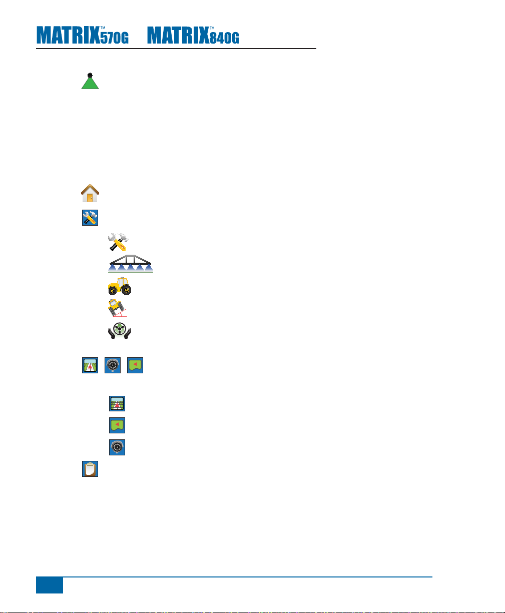
SYSTEM COMPONENTS
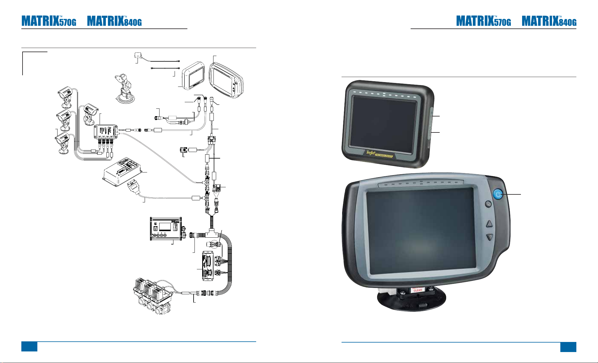
Matrix 570G Console
The Matrix 570G is designed to provide years of service under typical agricultural operating conditions. A
tight fi tting enclosure, combined with rubber covers for all connectors mean that typical dusty environments
will not cause operational problems. While occasional splashing of water will not damage the unit, the Matrix
570G is not designed for direct exposure to rain. Take care not to operate the Matrix in wet conditions.
Figure 1-1: Console Front & Back
Built In Lightbar
Power Button
USB Port with Rubber Cover
Bright Touch Screen
Standard RAM Bracket
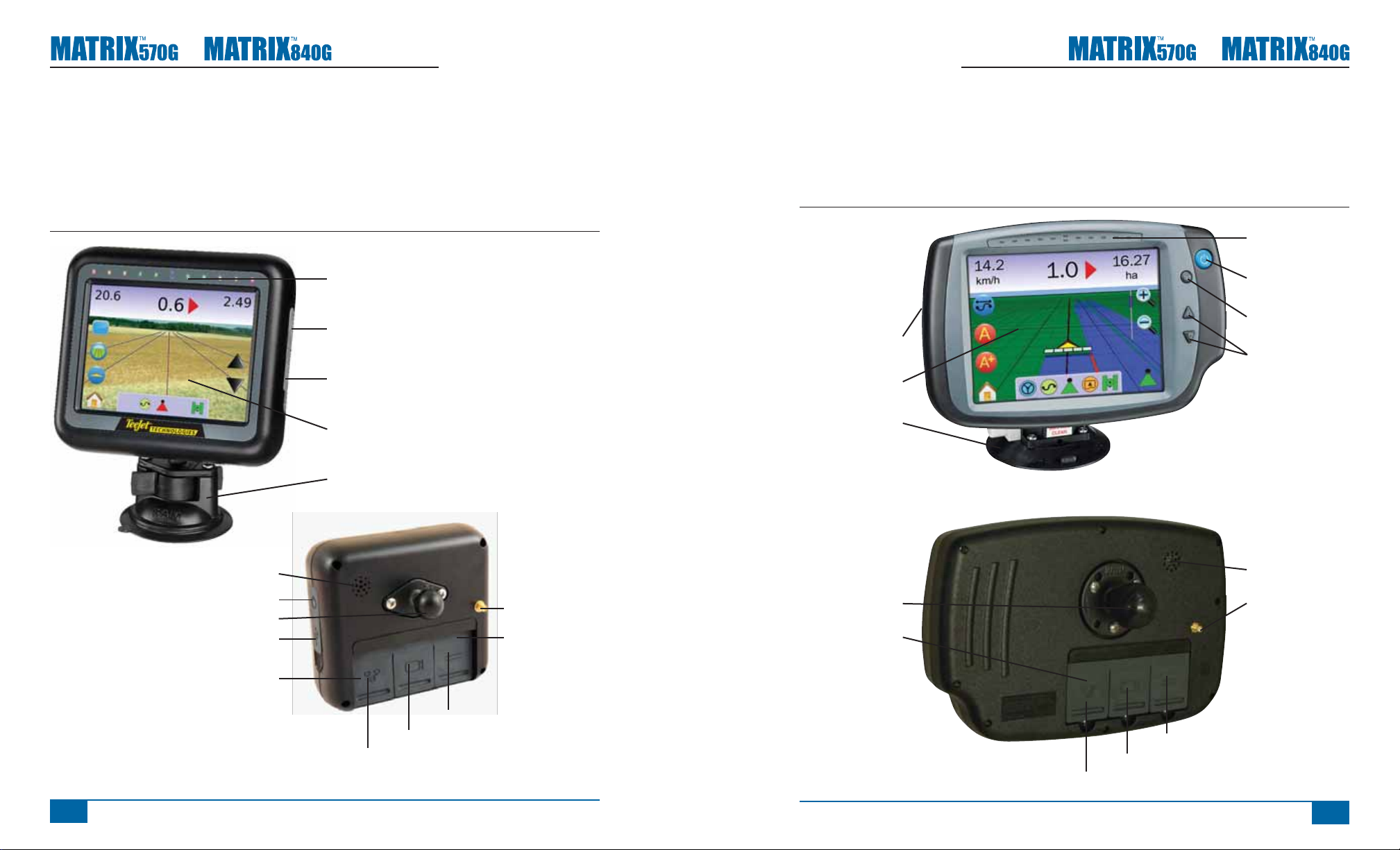
Matrix 840G Console
The Matrix 840G is designed to provide years of service under typical agricultural operating conditions. A
tight fi tting enclosure, combined with rubber covers for all connectors mean that typical dusty environments
will not cause operational problems. While occasional splashing of water will not damage the unit, the Matrix
840G is not designed for direct exposure to rain. Take care not to operate the Matrix in wet conditions.
Figure 1-2: Console Front & Back
Built In Lightbar
Power Button
Home Button
USB Port
with Rubber Cover
Bright Touch Screen
Standard RAM Bracket
Zoom In/Out Buttons
2
www.teejet.com
Speaker
Power Button
Integrated RAM Mount
USB Port with Rubber Cover
Recessed Connectors
Camera Connection
Power Connection
GPS Antenna
Connection
Rubber Connector
Covers
Speed Signal Connection
Integrated RAM Mount
Rubber Connector
Covers
Camera Connection
Power Connection
Speaker
GPS Antenna
Connection
Speed Signal Connection
98-05141 R2
3
Page 9
●
●
RealView Camera
The TeeJet Technologies RealView camera
allows video images to be displayed on the Matrix
screen. The camera can be pointed forward to
enable RealView guidance over video, or it can
be positioned to view other operational aspects of
your equipment. The camera is equipped with a
fl exible RAM mount, integral sun shade and provides
infrared illumination, allowing clear video images
even in dark conditions.
Figure 1-3: Video Camera
Sun Shade
Video Camera
Nighttime Illumination
Mounting Bracket
Video Selector Modules
A Video Selector Module (VSM) allows connection
of up to 8 video cameras to your Matrix console. The
module is compact and robust, and can be mounted
in any convenient location. No interaction is required
after installation.
Figure 1-4: Video Select Module - 4 Channel
Figure 1-5: Video Select Module - 8 Channel
GPS Antennas
TeeJet offers a full range of high-quality GPS
receivers to fi t your precision farming needs.
The RXA-25 or RXA-30 GPS antenna provides a
higher quality GPS receiver that can improve GPS
performance in areas of sub-optimal GPS reception.
Figure 1-6: GPS RXA-25 Antenna
Figure 1-7: GPS RXA-30 Antenna
FieldPilot
Steering Control Module
The FieldPilot Steering Control Module performs
assisted steering on straight and contour paths. The
Matrix system can link with the FieldPilot system
to take precise control of the vehicle position. The
operator manages the automatic steering system
with the Matrix – a benefi t of a single, in-cab
console. Automatic steering drives a vehicle with
tremendous, repeatable accuracy in both straight
and curved patterns. The ability to operate in fog or
dust, day or night with high levels of accuracy means
a better return on capital investment for equipment,
a more effective application and more attentive, alert
operation.
Figure 1-9: FieldPilot Steering Control Module
Matrix console connection is compatible with AgCam
cameras.
4
www.teejet.com
The Patch Antenna II provides strong performance in
standard operating conditions. The small size of the
patch antenna makes it easy to mount, and unlikely
to be damaged.
Figure 1-8: GPS Antenna
98-05141 R2
5
Page 10
●
●
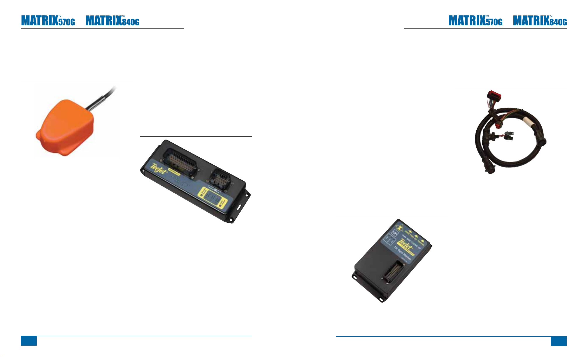
Foot Switch
TeeJet Foot Switch is a convenient method of
engaging FieldPilot. It is connected to the system via
the SCM Harness.
Figure 1-10: Foot Switch
BoomPilot
Section Driver Module
Combined with software built into the Matrix console,
the Section Driver Module (SDM) makes BoomPilot
(automatic boom section control) possible. The
SDM should be combined with the appropriate
cable to interface with your BoomPilot system,
spray controller and/or spraying machine for quick
and easy installation. Section Driver Modules and
their related cables are designed to control as many
boom sections as the spray controller to which they
are connect, up to a maximum of 15 boom sections.
Figure 1-11: Sections Driver Module
Tilt Gyro Module
If your GPS antenna is mounted 12 feet (4 meters)
above the ground, a 10% side slope can cause 2
feet (0.6 meter) of position error. The new TeeJet Tilt
Gyro Compensation Module corrects GPS position
errors caused by side slope conditions. Mounted
on a solid structure on your vehicle, the Tilt Gyro
Compensation Module will intercept GPS signals
from your receiver and provide corrected position
data to your guidance device.
• Diagnostic LEDs indicate status of TCM (Power
status, operating status, and status of incoming
GPS data)
• Weatherproof electrical connector for troublefree operation
• Mounting holes built into housing
• Automatically detects GPS sensor baud rate
and adjusts output accordingly
• Compatible with Matrix guidance systems
NOTE: If FieldPilot is being used, a TCM is built into
the system.
Figure 1-12: Tilt Gyro Module
Harnesses
TeeJet harnesses are designed for reliable operation
in harsh environments. Shielding and weatherproof
connections ensure that the cables and electrical
connections are reliable and trouble free.
Figure 1-13: Harness
Cable Extensions
Cable extensions or extended length cables are
available for special applications. Contact your
TeeJet dealer for details if the standard cables
provided with your system are not long enough.
6
www.teejet.com
Extended Warranty
TeeJet offers an extended warranty for many
guidance products. Not available in all markets.
Contact your TeeJet dealer for details.
98-05141 R2
7
Page 11
●
●
CONFIGURATIONS
The following diagrams are refl ective of typical Matrix confi gurations. Due to the variety of possible
confi gurations, these should be used for reference purposes only.
Figure 1-14: Matrix w/RealView Camera
Matrix
FieldPilot
BoomPilot
78-50155
GPS Ant.
Optional Accessory
Kit, RAM Mount w/Suction Cup
90-02349 (Matrix 570G)
90-02700 (Matrix 840G)
16-00022: Camera
45-05615 4 Pos.
45-05765 8 Pos.
Speed/Sense Cable
Matrix 570G
75-30055
75-30056 w/ClearPath
Speed Cable
Camera
Camera Extension Cable
32-50008
Switch
+12V
45-05617: 20'
45-05618: 60'
5 Pos.
4 Pos.
8 Pos.
45-05645
Power
Cable, 12V
Speed Out / Sense In Cable
The Speed Out / Sense In Cable assists the Matrix with two additional connections that::
►Send a radar speed signal to an external device
►Allow the user to operate the area applied function of the Matrix in series with a remote master connection
or existing apply on/off toggle in a single swath manner. However if the previous connections are not
available the supplied toggle switch allows area applied functionality without the need to connect to a
functional application implement.
Connecting to different consoles requires different adapters and calibrations.
• If connecting to TeeJet consoles use speed adapter 45-20042
◄enter calibration # 914 (#1000 in Europe) for 8xx series in RAD mode,
◄enter calibration # 9140 (#10000 in Europe) for below LH 70 Series, LH 85, 500 series, 5000, 6000,
IC 24 and IC 34
• If connecting to Mid-Tech consoles no adapter is required,
◄enter calibration # 1000
• If connecting to Raven consoles use speed adapter 45-05508 (do not connect the 12v red wire from
45-05508)
◄enter calibration # 730 in SP 2
If sensing boom shut-off for applied mapping from an existing console, attach the green wire to the valve side
of the master switch on the console. The red wire is not used.
Matrix 840G
75-30070
75-30071 w/ClearPath
POWER CABLE
DC: XXXX
Power Cable
45-05775
45-05775
10' Power
Connectto
+12v Only
Cable, Battery
CAUTION CONN.
TO +12V ONLY
8 Pos.
Figure 1-15: Matrix w/8 Channel or 4 Channel VSM & Multiple RealView Cameras
Matrix
FieldPilot
BoomPilot
Optional Accessory
16-00022
RealView Camera
Kit, RAM Mount w/Suction Cup
90-02349 (Matrix 570G)
90-02700 (Matrix 840G)
78-08067
Module, 4CH
Video CAN
78-50155
GPS Ant.
to Optional RXA GPS Antenna
Cable, SMA-M X SMA-M
45-05615 4 Pos.
45-05765 8 Pos.
Speed/Sense Cable
78-08068
Video Selector
Module,
8CH Video CAN
45-05678
Matrix 570G
75-30055
75-30056 w/ClearPath
Speed Cable
Camera
Camera Extension Cable
32-50008
Switch
+12V
45-05617: 20'
45-05618: 60'
CAN Terminator
5 Pos.
4 Pos.
8 Pos.
RS-232
RS-232
45-08101
Battery Adapter
401-0016
Matrix 840G
75-30070
75-30071 w/ClearPath
Power/DATA
45-05626
45-05626
Pwr/CAN/Data
Cable
(included with
FieldPilot and
BoomPilot kits)
CAN
POWER IN
Power Cable
DC: xx/xx
401-0016
WARNING CONNECT
DIRECTLY TO BAT.
8 Pos.
TJ CAN
(Terminated)
3A Fuse
CAUTION: CONNECT
TO 12V ONLY
8
www.teejet.com
98-05141 R2
9
Page 12
●
●
Figure 1-16: Matrix w/VSM & Multiple RealView Cameras, FieldPilot and BoomPilot
Matrix
FieldPilot
BoomPilot
Optional Accessory
16-00022
RealView Camera
Power
Kit, RAM Mount w/Suction Cup
45-07703
SCM Power I/O
SCM Power I/O
45-07703
DC: xx/xx
Valve Output
90-02349 (Matrix 570G)
90-02700 (Matrix 840G)
45-07708
SCM Harness
SCM COM 2
GPS In
COM 1
78-08067
Module, 4CH
Video CAN
Engage/Disengage
78-50155
GPS Ant.
to Optional RXA GPS Antenna
Remote
Cable, SMA-M X SMA-M
75-30056 w/ClearPath
45-05615 4 Pos.
45-05765 8 Pos.
Speed/Sense Cable
78-08061
Steering Control
Module (SCM)
GPS Power
Steering
Wheel Sense
Seat Sensor
45-05678
Matrix 570G
75-30055
Speed Cable
+12V
Camera
45-05617: 20'
45-05618: 60'
Camera Extension Cable
5 Pos.
4 Pos.
8 Pos.
32-50008
Switch
RS-232
RS-232
CAN
Matrix 840G
75-30070
75-30071 w/ClearPath
Power/DATA
45-05626
CAN
POWER IN
Remote ABSC
Status Switch
Connection
8 Pos.
45-05626
Pwr/CAN/Data
Cable
(included with
FieldPilot and
BoomPilot kits)
TJ CAN
(Terminated)
3A Fuse
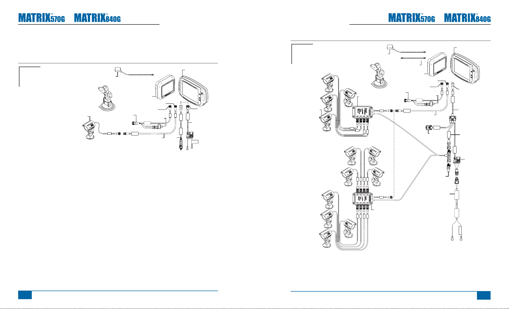
Figure 1-17: Matrix w/VSM & Multiple RealView Cameras and FieldPilot
Matrix
FieldPilot
BoomPilot
Optional Accessory
16-00022
RealView Camera
Power
Kit, RAM Mount w/Suction Cup
45-07703
SCM Power I/O
SCM Power I/O
45-07703
DC: xx/xx
Valve Output
90-02349 (Matrix 570G)
90-02700 (Matrix 840G)
45-07708
SCM Harness
SCM COM 2
GPS In
COM 1
78-08067
Module, 4CH
Video CAN
Engage/Disengage
78-50155
GPS Ant.
to Optional RXA GPS Antenna
Remote
Cable, SMA-M X SMA-M
75-30056 w/ClearPath
45-05615 4 Pos.
45-05765 8 Pos.
Speed/Sense Cable
78-08061
Steering Control
Module (SCM)
GPS Power
Steering
Wheel Sense
Seat Sensor
45-05678
Matrix 570G
75-30055
Speed Cable
Camera
Camera Extension Cable
32-50008
Switch
+12V
45-05617: 20'
45-05618: 60'
CAN Terminator
5 Pos.
4 Pos.
8 Pos.
RS-232
RS-232
45-08101
Matrix 840G
75-30070
75-30071 w/ClearPath
8 Pos.
Power/DATA
45-05626
45-05626
Pwr/CAN/Data
Cable
(included with
FieldPilot and
BoomPilot kits)
CAN
TJ CAN
(Terminated)
POWER IN
3A Fuse
CAN
45-05381
Battery 12'
w/15Amp
Fuses
10
45-10103
Harness
Steering
(A+B)
DC: xx/xx
45-05381
C
o
n
n
e
(
ct
+
1
o
2
t
v)
o
www.teejet.com
Harness
(A+B)
45-10103
DC: xx/xx
32-04040
Remote
Engage/
Disengage
Switch
Steering
Valve
Battery 12' w/15Amp Fuses
32-04020
32-04020
DC: xx/xx
Engage / Disengage
Optional
Footswitch
45-05381
C
o
n
(
+
1
DC: xx/xx
45-05381
n
e
ct
o
2
t
v)
o
98-05141 R2
11
45-10103
DC: xx/xx
Rate Controller
32-04040
Remote
Engage/
Disengage
Switch
Steering
Valve
32-04020
32-04020
DC: xx/xx
Engage / Disengage
Optional
Footswitch
BoomPilot Harness
dependent on Rate Controller
Part number
78-05077
BoomPilot
Section Driver
Module
(15 sections)
Console Harness
45-10103
Steering
Page 13
●
●
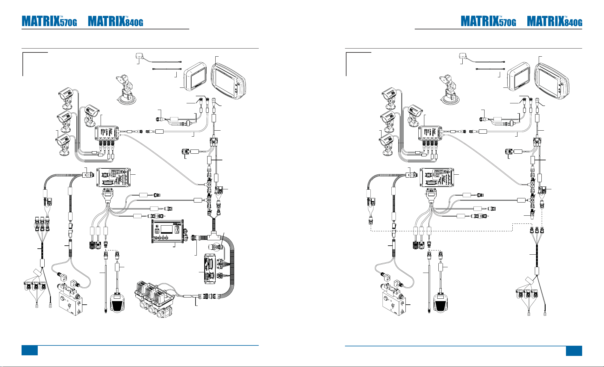
Figure 1-18: Matrix 570G w/VSM, Tilt Gyro and BoomPilot
Matrix
FieldPilot
BoomPilot
Optional Accessory
16-00022
RealView Camera
Kit, RAM Mount w/Suction Cup
90-02349 (Matrix 570G)
90-02700 (Matrix 840G)
78-08067
Module, 4CH
Video CAN
78-50155
GPS Ant.
to Optional RXA GPS Antenna
Cable, SMA-M X SMA-M
45-05615 4 Pos.
45-05765 8 Pos.
Speed/Sense Cable
45-07716
TGM Harness
45-05678
Matrix 570G
75-30055
75-30056 w/ClearPath
Speed Cable
Camera
Camera Extension Cable
78-08057
Tilt Gyro
Module (TGM)
32-50008
Switch
+12V
45-05617: 20'
45-05618: 60'
5 Pos.
4 Pos.
8 Pos.
RS-232
Matrix 840G
75-30070
75-30071 w/ClearPath
8 Pos.
Power/DATA
45-05626
45-05626
Pwr/CAN/Data
Cable
(included with
FieldPilot and
CAN
BoomPilot kits)
TJ CAN
(Terminated)
POWER IN
3A Fuse
RS-232
CAN
Press the power button to power on the console. Upon power up, the Matrix will begin its Start Up Sequence.
Press and briefl y hold the power button (until the screen turns black) to power off the console.
Figure 1-19: Power Button
Power Button
USB Port with Rubber
Cover
Power Button
POWER ON/OFF
12
www.teejet.com
Rate Controller
BoomPilot Harness
dependent on Rate Controller
Part number
Section Driver
(15 sections)
78-05077
BoomPilot
Module
Console Harness
Remote ABSC
Status Switch
Connection
98-05141 R2
13
Page 14
●
●
Start Up Sequence
The console takes approximately 40 seconds to
power up. During this time the TeeJet Technologies
logo will be displayed (LEDs will power on and off
and brightness levels will fl uctuate.)
Figure 1-20: Power Up Screen
Once the power up sequence has cycled, the
following message is displayed:
“Would you like to clear the job data and begin a
new job?”
1. Press
►No – The previous job will resume.
►Yes – A new job will be established and all
data from previous jobs will be cleared. The
message “All job data cleared” is displayed.
Select “OK” to continue.
The splash screen will be displayed for
approximately one minute.
The splash screen lists the module’s current
software version. The information is also available
on the About screen.
Figure 1-21: Clear Job Data Screens
Figure 1-22: Splash Screen
Matrix
v1.0
GENERAL OPERATION
INFORMATION
A fi rm touch is required when selecting a screen
icon.
On initial startup, the console will load the Vehicle
View screen as a default. All subsequent power
cycles will return to the last page viewed before
powering down.
Icons on guidance screens will be displayed and will
fade from the window after 6 seconds of inactivity. To
regain these icons, touch the screen in any location.
Figure 1-23: With and Without Icons On Screen
Press the icon of any menu item to display a
defi nition of that item. To remove the information
box, press anywhere on the screen.
Figure 1-24: Example of Information Text Box
For rapid adjustment of a setting, press and hold the
►PLUS/MINUS ICONS ,
►UP/DOWN ARROW ICONS
►ZOOM IN/OUT ICONS
►ZOOM IN/OUT BUTTONS (Matrix 840G
only).
The Zoom In/Out Buttons on the Matrix 840G
will not adjust Plus/Minus or Up/Down settings.
GPS Status Change – a pop-up warning will be
displayed for approximately 2.5 seconds. To remove
a pop-up sooner, press anywhere on the screen.
Figure 1-25: Example of GPS Status Change
NOTE: A firm touch is required when selecting or
acknowledging a screen option.
14
www.teejet.com
98-05141 R2
15
Page 15
●
●
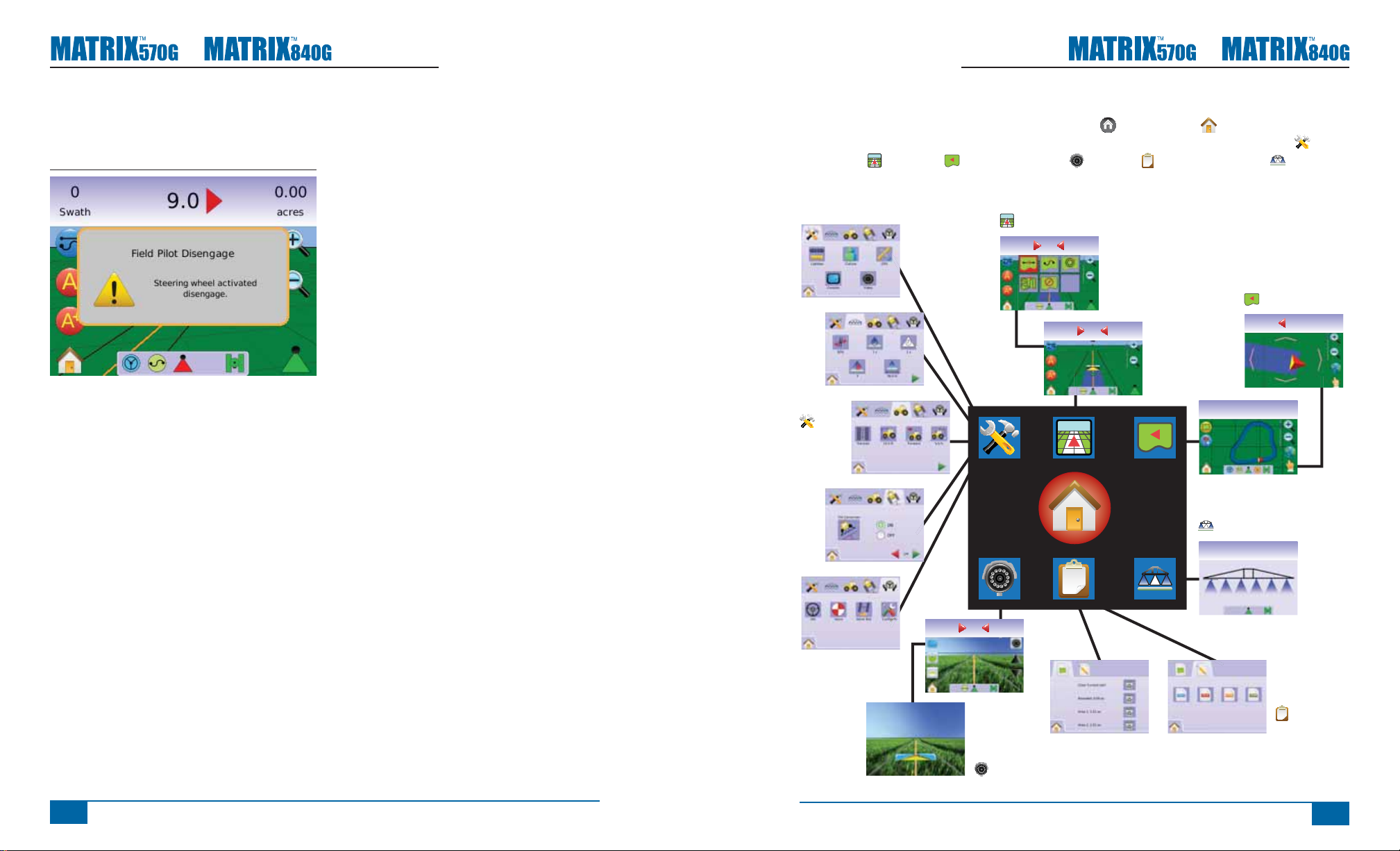
FieldPilot Disengaged – a pop-up warning will be
displayed for approximately 2.5 seconds. To remove
a pop-up sooner, press anywhere on the screen.
Figure 1-26: FieldPilot Disengaged Screen
All changes are saved automatically.
The Matrix is a current job system. Previous jobs
cannot be recalled.
The console needs to be cycled off and back on
when changing or attaching equipment to the Matrix
system.
Cleaning suggestions – Matrix consoles should be
cleaned with mild cleaners, such as glass cleaner,
and a soft cloth. Take care not to rub dust or other
abrasive materials into the touch screen surface.
• Use a soft lint-free cloth.
• The cloth may be used dry, or lightly dampened
with a mild cleaner or Ethanol.
• Be sure the cloth is only lightly dampened, not
wet. Never apply cleaner directly to touch panel
surface; if cleaner is spilled onto touch panel,
soak it up immediately with absorbent cloth.
• Cleaner must be neither acid nor alkali (neutral
pH).
• Wipe the surface gently; if there is a directional
surface texture, wipe in the same direction as
the texture.
• Never use acidic or alkaline cleaners, or
organic chemicals such as: paint thinner,
acetone, tolulene, xylene, propyl or isopropyl
alchohol, or kerosene.
• Suitable cleaning products are commercially
available pre-packaged for use; one example
of such a product is Klear Screen™, or
commercially available off-the-shelf retail
brands such as Glass Plus® Glass and Surface
Cleaner made by Reckitt-Benckiser.
• Use of incorrect cleaners can result in optical
impairment of touch panel and/or damage to
functionality.
Page Layout and Navigation
The Matrix is very simple to navigate. The HOME BUTTON or HOME ICON gives you access to the
unit’s 3 functions: Setup, Guidance and Monitoring. The 6 touch screen Menu Options (Unit Setup ,
Vehicle View , Field View , RealView Guidance , Job View and Boom Monitoring ) quickly
access all aspects of the unit.
Vehicle View Screens
3.570
0.0
Swath acres
Home
Field View Screens
1.3
3.570
mph acres
Swath acres
4.9212.4
10.010
Boom Monitoring Screen
mph acres
6.783.3
Job View
Screens
Unit
Setup
Screens
Swath acres
0.0
Swath acres
0.0
2.3-2
16
www.teejet.com
RealView Guidance Screens
98-05141 R2
17
Page 16
CHAPTER 2 – UNIT SETUP
Unit Setup is used to confi gure System Setup, BoomPilot/Single Boom Setup, Vehicle Setup, Tilt
Gyro Module Setup, and FieldPilot Setup.
NOTE: All settings are automatically saved when selected.
To access the Unit Setup screens:
1. Press HOME BUTTON or press the screen
to activate the icons and select HOME ICON
in bottom left corner of screen.
2. Select UNIT SETUP from Home Menu .
3. Select from:
●
► Tilt Gyro Module Setup – used to
calibrate the Tilt Gyro Module, allowing for tilt
correction for application on hilly or sloped
terrain.
► FieldPilot Setup – used to confi gure:
► System Setup – used to confi gure:
◄ Lightbar – used to confi gure LED
Spacing , Display/Swath Mode and
LED Brightness settings.
◄ Culture – used to confi gure Units ,
Language and Time Zone .
◄ GPS – used to confi gure GPS
Type and the GPS Port , as well
as view GPS Status information .
◄ Console – used to confi gure
Volume , LCD Brightness , Screen
Calibrate and Screenshot settings,
as well as view About information and
Save system software information .
◄ Video – used to set up individual
cameras A B C D E F G H.
► BoomPilot/Single Boom Setup – used
to confi gure Overlap , Delay On ,
Delay Off , Number of Boom Sections #
and Boom Section Width settings.
◄ Enable/Disable FieldPilot .
◄ Valve Setup – used to confi gure
Valve Frequency, Minimum Duty Cycle
Left, Minimum Duty Cycle Right and
Maximum Duty Cycle settings.
◄ Valve Test – verifi es steering is
directed correctly and is used to fi ne
tune the oil fl ow.
◄ Confi gure FieldPilot – used to
confi gure Coarse Steering Adjustment,
Fine Steering Adjustment, Deadband,
and Lookahead settings.
General Information
Press the icon of any menu item to display a
defi nition of that item. To remove the information
box, press anywhere on the screen.
Figure 2-1: Example of Information Text Box
► Vehicle Setup – used to confi gure
Vehicle Type
Direction to Boom
Distance settings.
, Antenna Height ,
and Boom Offset
98-05141 R2
19
Page 17
●
●
Home Menu
The Home Button or Home Icon gives you
access to the unit’s three functions: Setup, Guidance
and Monitoring. The six touch screen Menu Options
(Unit Setup , Vehicle View , Field View ,
RealView Guidance , Job View and Boom
Monitoring ) quickly access all aspects of the unit.
To view the Home Menu options:
1. Press HOME BUTTON or select HOME
ICON in bottom left corner of screen.
Figure 2-2: Home Menu - Unit Setup
SYSTEM SETUP
System Setup is used to confi gure
Lightbar, Culture, GPS, Console and
Video settings.
1. Select UNIT SETUP from Home Menu .
2. Press SYSTEM SETUP TAB .
3. Select from:
►Lightbar – used to confi gure LED Spacing,
Display Mode and LED Brightness
►Culture – used to confi gure Units,
Language and Time Zone
►GPS – used to confi gure GPS Type and
the GPS Port, as well as view GPS Status
information
►Console – used to confi gure Volume, LCD
Brightness, Screen Calibrate and Screenshot
settings, as well as view About information and
Save system software information
►Video – used to set up individual cameras
Figure 2-3: System Setup
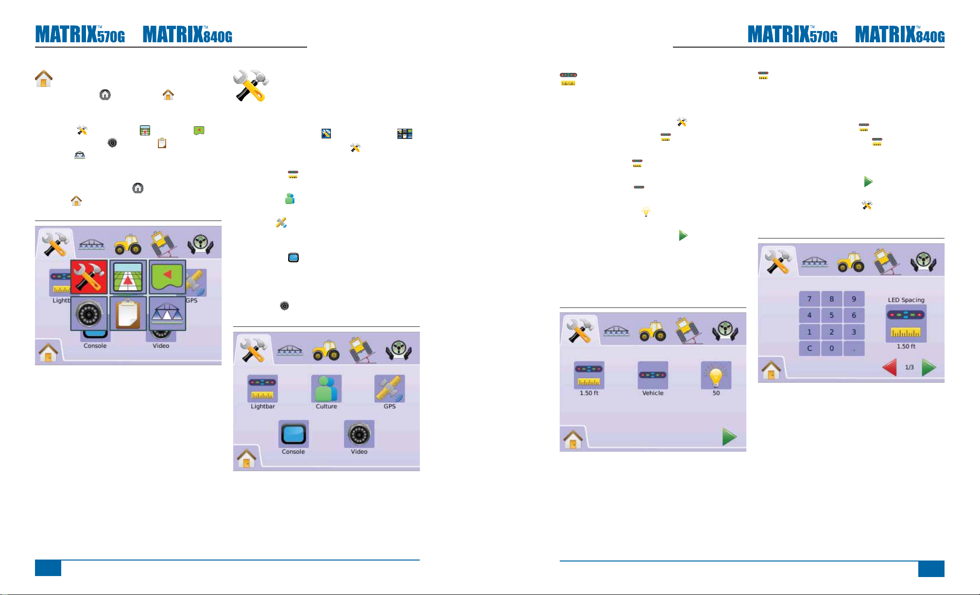
Lightbar
Lightbar Setup is used to confi gure LED Spacing,
Display/Swath Mode and LED Brightness.
1. Press SYSTEM SETUP TAB
2. Press LIGHTBAR ICON .
3. Select from:
►LED Spacing – sets the distance
illustrated by the illuminated LEDs
►Display Mode – determine whether the
lightbar represents the swath or vehicle
►LED Brightness – adjust LED brightness
OR
Press PAGE RIGHT ARROW to cycle through
all settings.
NOTE: Options labels are current settings. While in
a setting screen, press icon to view available
factory settings and setting ranges.
Figure 2-4: Lightbar Options
LED Spacing
LED Spacing sets the distance illustrated by the
illuminated LEDs. Range is 0.04 - 9.8 feet / 0.01 -
3.0 meters.
1. Press LIGHTBAR ICON .
2. Press LED SPACING ICON .
3. Use the entry screen to establish LED Spacing.
4. Press
►PAGE RIGHT ARROW to proceed to
Display Mode.
►SYSTEM SETUP TAB to return to main
System Setup screen.
Figure 2-5: LED Spacing
20
www.teejet.com
98-05141 R2
21
Page 18
●
●
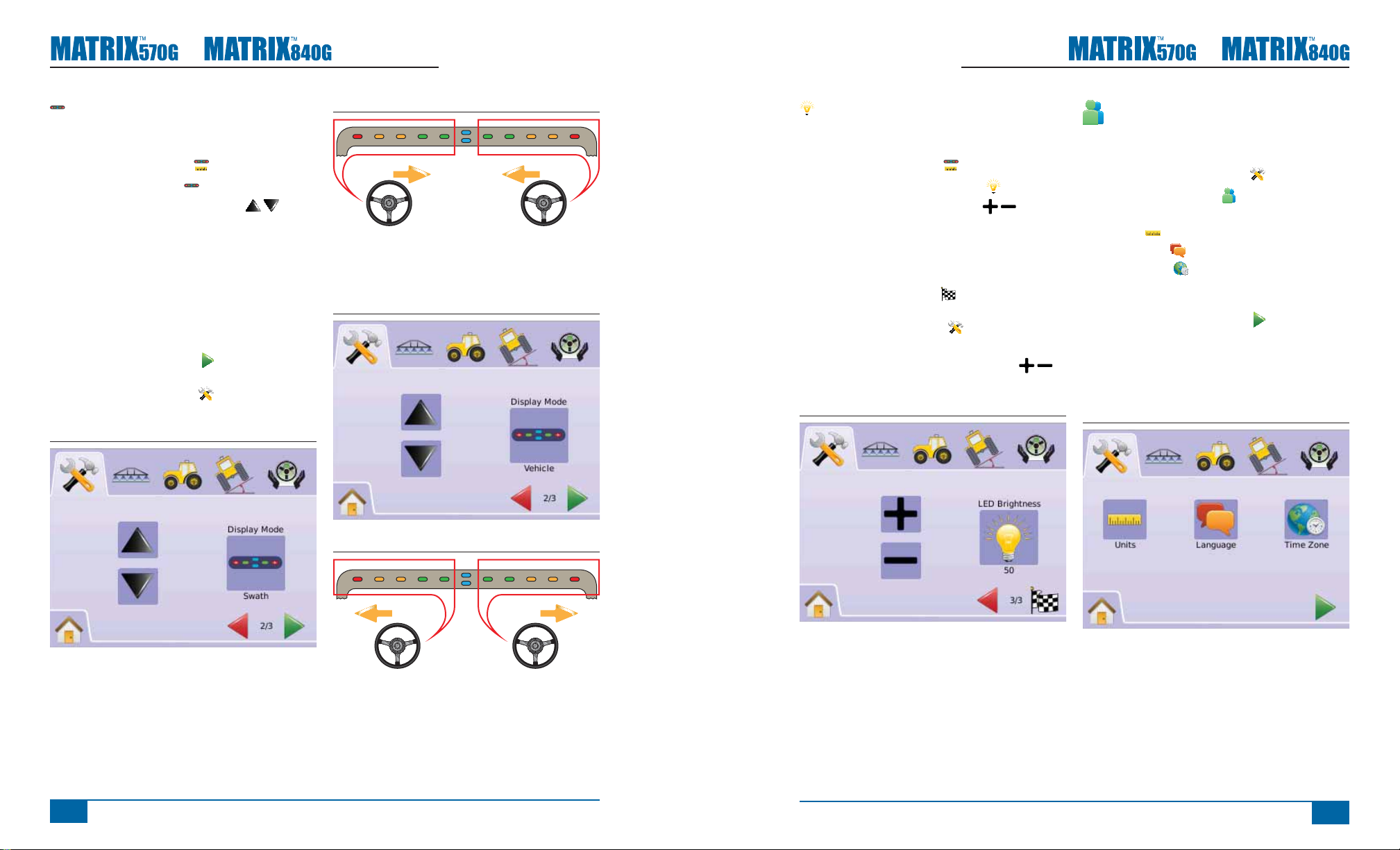
Display Mode
Display/Swath Mode determines whether the lightbar
represents the swath or vehicle.
1. Press LIGHTBAR ICON .
2. Press DISPLAY ICON .
3. Press UP/DOWN ARROW ICONS to
change between:
►Swath – the LEDs represent the guideline
location and the moving LED represents the
vehicle.
►Vehicle – the center LED represents vehicle
location and the moving LED represents the
guideline.
4. Press
►PAGE RIGHT ARROW to proceed to LED
Brightness.
►SYSTEM SETUP TAB to return to main
System Setup screen.
Figure 2-6: Display Mode - Swath
Figure 2-7: Swath Lightbar
Lights illuminated on the left of
the Lightbar require a steering
adjustment to the right.
Figure 2-8: Display Mode - Vehicle
right of the Lightbar require a
steering adjustment to the left.
Lights illuminated on the
LED Brightness
LED Brightness adjusts the brightness of the lightbar
LEDs. Range is 0 - 100.
1. Press LIGHTBAR ICON .
2. Press LED BRIGHTNESS ICON .
3. Press the PLUS/MINUS ICONS to adjust
LED brightness.
◄Higher the number, the brighter the LEDs.
◄Lower the number, the dimmer the LEDs.
4. Press
►CHECKERED FLAG to complete Lightbar
Setup.
►SYSTEM SETUP TAB to return to main
System Setup screen.
NOTE: Press & hold PLUS/MINUS ICONS to
quickly adjust settings.
Figure 2-10: LED Brightness
Culture
Culture is used to confi gure Units, Language and
Time Zone settings.
1. Press SYSTEM SETUP TAB
2. Press CULTURE ICON .
3. Select from:
►Units – defi nes the system measurements
►Language – defi nes the system language
►Time Zone – establishes the local time
zone
OR
Press PAGE RIGHT ARROW to cycle through
all settings.
NOTE: Options labels are current settings. While in
a setting screen, press icon to view available
factory settings and setting ranges.
Figure 2-11: Culture
22
www.teejet.com
Figure 2-9: Vehicle Lightbar
Lights illuminated on the left of
the Lightbar require a steering
adjustment to the left.
Lights illuminated on the right of
the Lightbar require a steering
adjustment to the right.
98-05141 R2
23
Page 19

●
●
Units
Units defi nes the system measurements (U.S. or
Metric).
1. Press CULTURE ICON .
2. Press UNITS ICON .
3. Press UP/DOWN ARROW ICONS to
change between:
►U.S.
►Metric.
4. Press
►PAGE RIGHT ARROW to proceed to
Language.
►SYSTEM SETUP TAB to return to main
System Setup screen.
NOTE: This setting is required for FieldPilot and
Tilt Sensor Operation, as well as proper
BoomPilot operation.
Figure 2-12: Units
Language
Languages defi nes the system language. Options
include Czech, Danish, Dutch, English, French,
German, Hungarian, Italian, Polish, Portuguese,
Russian, Spanish and Swedish.
1. Press CULTURE ICON .
2. Press LANGUAGE ICON .
3. Press UP/DOWN ARROW ICONS to
change between languages.
4. Press
►PAGE RIGHT ARROW to proceed to Time
Zone.
►SYSTEM SETUP TAB to return to main
System Setup screen.
NOTE: Press & hold UP/DOWN ARROW
ICONS to quickly adjust settings.
NOTE: This setting is required for FieldPilot and
Tilt Sensor Operation, as well as proper
BoomPilot operation.
Figure 2-13: Language
Time Zone
Time zone establishes the local time zone.
1. Press CULTURE ICON .
2. Press TIME ZONE ICON .
3. Press UP/DOWN ARROW ICONS to
select the appropriate time zone.
4. Press
►CHECKERED FLAG to complete Culture
Setup.
►SYSTEM SETUP TAB to return to main
System Setup screen.
NOTE: Press & hold UP/DOWN ARROW
ICONS to quickly adjust settings.
Figure 2-14: Time Zone
GPS
GPS is used to confi gure GPS Type and the GPS
Port, as well as view GPS Status information.
1. Press SYSTEM SETUP TAB
2. Press GPS ICON .
3. Select from:
►GPS Type – select GPS source
transmissions
►GPS Port – sets (D)GPS COM port
►GPS Status – displays information on
GGA/VTG (Data Rates), Num Sat, HDOP, PRN
and Quality.
OR
Press PAGE RIGHT ARROW to cycle through
all settings.
NOTE: Options labels are current settings. While in
a setting screen, press icon to view available
factory settings and setting ranges.
Figure 2-15: GPS
24
www.teejet.com
Time zones are listed alphabetically by continent
then city. A list of the continents and cities is in
Appendix B.
98-05141 R2
25
Page 20

●
●
GPS Type
GPS Type customizes system to accept GPS source
or DGPS source transmissions.
1. Press GPS ICON .
2. Press GPS TYPE ICON .
3. Select
►GPS Only – uncorrected signals
►DGPS Only – differentially corrected signals
►GPS/DGPS – either type of signal
4. Press
►PAGE RIGHT ARROW to proceed to GPS
Port.
►SYSTEM SETUP TAB to return to main
System Setup screen.
NOTE: This setting is required for FieldPilot and
Tilt Sensor Operation, as well as proper
BoomPilot operation.
Figure 2-16: GPS Type
GPS Port
GPS Port sets port transmission to Internal or
External.
1. Press GPS ICON .
2. Press GPS PORT ICON .
3. Select
►Internal – use the internal (D)GPS (if
equipped) and transmit out
►External – receive external (D)GPS data
4. Press
►PAGE RIGHT ARROW to proceed to GPS
Status.
►SYSTEM SETUP TAB to return to main
System Setup screen.
NOTE: This setting is required for FieldPilot and
Tilt Sensor Operation, as well as proper
BoomPilot operation.
Figure 2-17: GPS Port
External Receiver Minimum Confi guration
Requirements
Before the Matrix will connect and work with an
external GPS receiver, these minimum confi guration
requirements must be met.
Serial Port Settings
Baud rate: 19,200
Data Bits: 8
Parity: None
Stop Bits: 1
Serial Port connection requirements
Male 9 pin RS-232 serial cable
NOTE: May require Null modem adapter
depending on pin out of receiver.
NMEA Strings
GGA 5 Hz
VTG 5 Hz
ZDA 0.2 Hz
GPS Status
GPS Status displays information regarding data
rates, number of satellites in view, and satellite
quality and ID.
1. Press GPS ICON .
2. Press GPS PORT ICON to view data
including:
◄GGA/VTG (Data Rates) – the number of GPS
positions per second.
◄Num Sats – the number of GPS satellites in
view (minimum of 4 are required for DGPS)
◄HDOP – a measure of satellite geometry
strength in the horizontal plane. A HDOP value
of less than 2 is preferred.
◄PRN – the current DGPS satellite ID. (see
PRN chart)
◄GGA Quality – the current quality indicator of
the GPS signal. (see GGA chart)
3. Press
►CHECKERED FLAG to complete GPS
Setup.
►SYSTEM SETUP TAB to return to main
System Setup screen.
NOTE: If GPS is not available, all entries will be
“Invalid”
26
www.teejet.com
NOTE: Working with GPS signals such as Omnistar
HP/XP or RTK will require GPS port to be
set to External.
Figure 2-18: GPS Status
98-05141 R2
27
Page 21

●
●
PRN
Location PRN
Western US 135
Eastern US 138
Central US 135 or 138
South America N/A
Europe 120 or 124
GGA Requirements
GGA Quality required to be able to work with
various types of signal can vary. See table below for
requirements.
Service GGA
Quality
Omnistar HP/XP 5 10 cm
RTK 4 4 cm
Glide 9 <1 m
WAAS/EGNOS/Beacon 2 <1 m
GPS only 1 <3 m
Accuracy
Console
Console Setup is used to confi gure Volume, LCD
Brightness, Screen Calibrate and Screenshot
settings, as well as view About information and Save
system software information.
1. Press SYSTEM SETUP TAB
2. Press CONSOLE ICON .
3. Select from:
►Volume – adjusts the volume level of the
audio speaker
►LCD Brightness – adjusts the brightness
of the console display
►Touch Screen Calibration – used to force
a touch screen calibration
►Screenshot – allows screen images to be
saved a USB drive
►About/Save – displays the system
software version as well as the software versions
of modules connected to the CAN bus
OR
Press PAGE RIGHT ARROW to cycle through
all settings.
NOTE: While in a setting screen, press icon to view
available factory settings and setting ranges.
Volume
Volume adjusts the volume level of the audio
speaker. Range is 0 - 100.
1. Press CONSOLE ICON .
2. Press VOLUME ICON .
3. Press the PLUS/MINUS ICONS to adjust
volume level.
◄Higher the number, the louder the sound.
◄Lower the number, the softer the sound.
4. Press
►PAGE RIGHT ARROW to proceed to LCD
Brightness.
►SYSTEM SETUP TAB to return to main
System Setup screen.
NOTE: Press & hold PLUS/MINUS ICONS to
quickly adjust settings.
Figure 2-20: Volume
LCD Brightness
LCD Brightness adjusts the brightness of the
console display. Range is 0 - 100.
1. Press CONSOLE ICON .
2. Press LCD BRIGHTNESS ICON .
3. Press the PLUS/MINUS ICONS to adjust
LED brightness.
◄Higher the number, the brighter the LCD.
◄Lower the number, the dimmer the LCD.
4. Press
►PAGE RIGHT ARROW to proceed to
Touch Screen Calibration.
►SYSTEM SETUP TAB to return to main
System Setup screen.
NOTE: Press & hold PLUS/MINUS ICONS to
quickly adjust settings.
WARNING!: In hot conditions, settings above 50
may cause a High Temperature Warning.
The console will automatically dim the
screen to reduce the console temperature.
Figure 2-21: LCD Brightness
28
www.teejet.com
Figure 2-19: Console
98-05141 R2
29
Page 22

●
●
Touch Screen Calibration with
Software Version 1.00 to 1.02
Touch Screen Calibration is used to force a touch
screen calibration the next time a power cycle
occurs.
1. Press CONSOLE ICON .
2. Press CALIBRATE TOUCH SCREEN ICON .
3. Press HAND ICON to enable the touch
screen calibration process.
4. “Force touch screen calibration next time unit
starts up?”
Press
►Yes – to return to the Touch Screen
Calibration screen. The calibration will be
performed when power to the console is cycled.
►No – to return to the Touch Screen Calibration
screen
5. Press
►PAGE RIGHT ARROW to proceed to
Screenshot.
►SYSTEM SETUP TAB to return to main
System Setup screen.
Figure 2-22: Touch Screen Calibration
Figure 2-23: Touch Screen Calibration
Next Power Cycle
The calibration screen will be displayed before the
console boots.
1. “TSLIB calibration utility Touch crosshair to
calibrate”
Press series of 5 crosshairs .
2. Console will resume booting.
After the fi fth (5th) crosshair is pressed, the
calibration process takes approximately 30 - 45
seconds to complete.
Touch Screen Calibration with
Software Version 1.03
Touch Screen Calibration is used to activate a touch
screen calibration.
1. Press CONSOLE ICON .
2. Press CALIBRATE TOUCH SCREEN ICON .
3. Press HAND ICON to enable the touch
screen calibration process.
4. “Begin touch screen calibration?”
Press
►Yes – to begin the Touch Screen Calibration.
►No – to return to the Touch Screen Calibration
screen
5. Press series of 5 crosshairs .
6. Press OK to complete the touch screen
calibration.
7. Press
►PAGE RIGHT ARROW to proceed to
Screenshot.
►SYSTEM SETUP TAB to return to main
System Setup screen.
Figure 2-25: Touch Screen Calibration
Figure 2-26: Touch Screen Calibration Process
30
www.teejet.com
Figure 2-24: Touch Screen Calibration Process
TSLIB calibration utility
Touch crosshair to calibrate
98-05141 R2
31
Page 23

●
●
Screenshot
To aid when troubleshooting problems in the fi eld,
an end user can use Screenshot to save a screen
to a USB drive, then e-mail the image to support
personnel.
When Screenshot is enabled, a SCREENSHOT
ICON is displayed on the upper right of each
screen.
Enable/Disable
1. Press CONSOLE ICON .
2. Press SCREENSHOT ICON .
3. Select
►Enable
►Disable
4. Press
►PAGE RIGHT ARROW to proceed to
About/Save.
►SYSTEM SETUP TAB to return to main
System Setup screen.
Figure 2-27: Screenshot
Capture an Image
1. Insert a USB drive into the USB port.
2. Press the SCREENSHOT ICON
NOTE: Screenshot does not capture live feed from
video.
Figure 2-28: Example of Screenshot on Screen
.
About/Save
About/Save screen displays the system software
version as well as the software versions of modules
connected to the CAN bus.
To view system information:
1. Press CONSOLE ICON .
2. Press ABOUT ICON to view data including:
◄Unit Model Number
◄Software Version
◄Connected Modules
3. Press
►CHECKERED FLAG to complete Console
Setup.
►SYSTEM SETUP TAB to return to main
System Setup screen.
Figure 2-29: About Matrix 570G
Figure 2-30: About Matrix 840G
Save About Information
To aid when troubleshooting problems in the fi eld,
an end user can use Save to download a text fi le
containing current software information to a USB
drive, then e-mail the fi le to support personnel.
1. Press CONSOLE ICON
2. Press ABOUT ICON .
3. Insert a USB drive in the USB port.
4. Press the SAVE ICON .
“Saved version information to USB drive” will
confi rm save.
5. Press
►CHECKERED FLAG to complete Console
Setup.
►SYSTEM SETUP TAB to return to main
System Setup screen.
NOTE: The SAVE ICON is not available for
selection (grayed out) until a USB drive is
inserted properly.
Figure 2-31: About Verification
.
32
www.teejet.com
98-05141 R2
33
Page 24

●
●
Video
Video Setup is used to set up individual cameras
while using a Eight (8) Channel or Four (4) Channel
Video Selector Module (VSM). Up to 8 cameras can
be confi gured if a VSM is installed.
NOTE If a VSM is not installed, VIDEO SETUP
is not available for selection (grayed out) .
Figure 2-32: Video Unavailable
NOTE: Video Setup will not change the setting of
a directly connected camera even when a
VSM is on the system. Adjusting options will
not affect a direct camera attachment.
Eight Channel VSM
When a eight (8) channel VSM is on the system, up
to eight (8) cameras can be installed and confi gured.
1. Press SYSTEM SETUP TAB
2. Press VIDEO ICON .
3. Select
►Camera A A
B
►Camera B
►Camera C C
►Camera D D
►Camera E E
►Camera F F
►Camera G G
►Camera H H
OR
Press PAGE RIGHT ARROW to cycle through
all cameras.
4. Select the appropriate check box(s):
►Normal –
►Reverse –
►Upside Down –
►Reverse & Upside Down –
5. Press PAGE RIGHT ARROW to cycle through
remaining cameras.
6. Press
►CHECKERED FLAG to complete Video
Setup.
►SYSTEM SETUP TAB to return to main
System Setup screen.
Figure 2-33: Video w/Eight Channel VSM
Figure 2-34: Camera Configuration
8 Channel VMS w/Only A, B, C & D
If cameras are only installed in ports A, B, C and
D, cameras E, F, G and H will not be available for
confi guring.
Figure 2-35: Camera Configuration
Four Channel VSM
When a four (4) channel VSM is on the system, up
to four (4) cameras can be installed. Only Cameras
A, B, C and D will be available for setup.
1. Press SYSTEM SETUP TAB
2. Press VIDEO ICON .
3. Select
►Camera A A
►Camera B B
►Camera C C
►Camera D D
OR
Press PAGE RIGHT ARROW to cycle through
all cameras.
4. Select the appropriate check box(s):
►Normal –
►Reverse –
►Upside Down –
►Reverse & Upside Down –
5. Press PAGE RIGHT ARROW to cycle through
remaining cameras.
6. Press
►CHECKERED FLAG to complete Video
Setup.
►SYSTEM SETUP TAB to return to main
System Setup screen.
34
www.teejet.com
98-05141 R2
35
Page 25

●
●
Figure 2-36: Video w/Four Channel VSM
Figure 2-37: Camera Configuration
BOOMPILOT/SINGLE
BOOM SETUP
BoomPilot Setup is used to confi gure
Overlap, Delay On, Delay Off, Number of Boom
Sections, and Boom Section Width settings.
Single Boom Setup is available when a SmartCable
or Section Driver Module (SDM) is not present.
Confi gurations for Overlap, Delay On, Delay Off,
Number of Boom Sections will not be available, and
only one boom section width can be entered.
BoomPilot Setup
If a SmartCable or Section Driver Module (SDM)
is present, up to 15 boom section widths can be
entered.
1. Select UNIT SETUP from Home Menu .
2. Press BOOMPILOT/SINGLE BOOM SETUP
TAB
3. Select from:
►Overlap – determines the amount of
overlap allowed
►Delay On – establishes the timing for the
boom section valves to switch on
►Delay Off – establishes the timing for the
boom section valves to switch off
►Number of Boom Sections # – establishes
the number of available boom sections
►Boom Section Width – establishes the
width of each boom section
OR
Press PAGE RIGHT ARROW to cycle through
all settings.
NOTE: Options labels are current settings. While in
a setting screen, press icon to view available
factory settings and setting ranges.
NOTE: BoomPilot settings are only visible and
necessary if a SmartCable or SDM is
present. If neither is present, see Single
Boom Setup section.
Figure 2-38: Boom Section Setup (SDM detected)
Overlap
Overlap determines the amount of overlap allowed
when the boom sections are turned on and off using
BoomPilot.
1. Press OVERLAP ICON .
2. Press UP/DOWN ARROW ICONS to
change between:
►0%
►50%
►100%
3. Press
►PAGE RIGHT ARROW to proceed to Delay
On.
►BOOMPILOT/SINGLE BOOM SETUP TAB
to return to main Boom Section Setup screen.
Figure 2-39: Overlap
Figure 2-40: Examples of Overlap
0%
50%
100%
36
www.teejet.com
98-05141 R2
37
Page 26

●
Delay On
Delay On functions as a “look ahead” for establishing
the timing for the boom section valves to switch on
exactly when entering an area that has not been
applied. If the boom turns on too soon when entering
a non-applied area, decrease the Delay On setting.
If the boom turns on too late when entering a nonapplied area, increase the Delay On setting. Range
is 0.0 - 10.0 seconds.
1. Press DELAY ON ICON .
2. Use the entry screen to establish delay time.
3. Press
►PAGE RIGHT ARROW to proceed to Delay
Off.
►BOOMPILOT/SINGLE BOOM SETUP TAB
to return to main Boom Section Setup screen.
Figure 2-41: Delay On
Delay Off
Delay Off functions as a “look ahead” for establishing
the timing for the boom section valves to switch
off exactly when entering an area that has been
applied. If the boom turns off too soon when entering
an applied area, decrease the Delay Off setting. If
the boom turns off too late when entering an applied
area, increase the Delay Off setting. Range is 0.0 -
10.0 seconds
1. Press DELAY OFF ICON .
2. Use the entry screen to establish delay time.
3. Press
►PAGE RIGHT ARROW to proceed to
Number of Boom Sections.
►BOOMPILOT/SINGLE BOOM SETUP TAB
to return to main Boom Section Setup screen.
Figure 2-42: Delay Off
#
Number of Boom Sections
Number of Boom Sections establishes the number
of available boom sections, 1 to 15 depending upon
which SmartCable or Section Driver Module (SDM)
is detected.
1. Press NUMBER OF BOOMS ICON #.
2. Press UP/DOWN ARROW ICONS to
establish appropriate number of boom sections.
3. Press
►PAGE RIGHT ARROW to proceed to Boom
Section Width.
►BOOMPILOT/SINGLE BOOM SETUP TAB
to return to main Boom Section Setup screen.
NOTE: Press & hold UP/DOWN ARROW
ICONS to quickly adjust settings.
NOTE: A section of more than one boom will change
the total steps to complete the BoomPilot
setup respectively.
Figure 2-43: Number of Boom Sections
●
Boom Section Width
Boom Section Width establishes the width of each
boom section. Range is 0.0 - 1968.5 inches / 0.0 -
50.0 meters. When facing forward, boom sections
are ordered from left to right along the boom.
1. Press BOOMPILOT/SINGLE BOOM SETUP
TAB .
2. Press BOOM SECTION WIDTH ICON .
3. Use the entry screen to establish boom section
width.
4. Press
►PAGE RIGHT ARROW to proceed to the
remaining individual boom section widths.
►CHECKERED FLAG to complete Boom
Section Setup.
►BOOMPILOT/SINGLE BOOM SETUP TAB
to return to main Boom Section Setup screen.
NOTE: When entering Boom Section Width, the
total of all sections must be greater than 34
inches / 0.9 meters.
NOTE Individual boom sections can be set to
different widths.
NOTE: This setting is required for FieldPilot
Operation.
38
www.teejet.com
Figure 2-44: Boom Section Width
98-05141 R2
39
Page 27

●
●
Single Boom Setup
Single Boom Setup is available when a SmartCable
or Section Driver Module (SDM) is not present.
Confi gurations for Overlap, Delay On, Delay Off,
Number of Boom Sections will not be available, and
only one boom section width can be entered.
Boom Section Width
Boom Section Width establishes the width of entire
swath. Range is 34.0 - 1968.5 inches / 0.9 - 50.0
meters.
1. Select UNIT SETUP from Home Menu .
2. Press BOOMPILOT/SINGLE BOOM SETUP
TAB .
3. Press
►BOOM SECTION WIDTH ICON .
►PAGE RIGHT ARROW .
4. Use the entry screen to establish swath width.
5. Press
►CHECKERED FLAG to complete Boom
Section Setup.
►BOOMPILOT/SINGLE BOOM SETUP TAB
to return to main Boom Section Setup screen.
NOTE: Options label is current setting. While in a
setting screen, press icon to view available
factory settings and setting ranges.
NOTE: This setting is required for FieldPilot and Tilt
Sensor Operation.
Figure 2-45: Single Boom Section Width (No SDM)
Figure 2-46: Single Boom Section Width Entry
VEHICLE SETUP
Vehicle Setup is used to confi gure
Vehicle Type, Antenna Height, Direction
to Boom, and Boom Offset Distance.
1. Select UNIT SETUP
2. Press VEHICLE SETUP TAB .
3. Select from:
►Vehicle Type – selects the type of
vehicle that most closely represents your vehicle
►Antenna Height – sets the height of the
antenna from the ground
►Direction to Boom – sets whether the
boom is located behind or in front of the GPS
antenna
►Boom Offset Distance – defi nes the
distance from the GPS antenna to the boom
OR
Press PAGE RIGHT ARROW to cycle through
all settings.
NOTE: Options labels are current settings. While in
a setting screen, press icon to view available
factory settings and setting ranges.
Figure 2-47: Vehicle Setup
from Home Menu .
Vehicle Type
Vehicle Type selects the type of vehicle steering that
most closely represents your vehicle.
1. Press VEHICLE TYPE ICON
2. Press UP/DOWN ARROW ICONS to
change between:
►Front Wheel Steer (also used for
Combines)
►Articulated
►Tracked
3. Press
►PAGE RIGHT ARROW to proceed to
Antenna Height.
►VEHICLE SETUP TAB to return to main
Vehicle Setup screen.
NOTE: This setting is required for FieldPilot and
Tilt Sensor Operation, as well as proper
BoomPilot operation.
Figure 2-48: Vehicle Type
40
www.teejet.com
98-05141 R2
41
Page 28

●
●
Antenna Height
Antenna Height sets the height of the antenna from
the ground. Range is 0.0 - 32.8 feet / 0.0 - 10.0
meters.
1. Press ANTENNA HEIGHT ICON .
2. Use the entry screen to establish the antenna
height.
3. Press
►PAGE RIGHT ARROW to proceed to
Direction to Boom.
►VEHICLE SETUP TAB to return to main
Vehicle Setup screen.
NOTE: This setting is required for FieldPilot and
Tilt Sensor Operation, as well as proper
BoomPilot operation.
Figure 2-49: Antenna Height
Direction to Boom
Direction to Boom sets whether the boom is located
behind or in front of the GPS antenna as the vehicle
moves in a forward direction.
1. Press DIRECTION TO BOOM ICON
2. Press UP/DOWN ARROW ICONS to
change between:
►Backward – indicates the boom is located
behind the GPS antenna
►Forward – indicates the boom is located
in front of the GPS antenna
3. Press
►PAGE RIGHT ARROW to proceed to Boom
Offset Distance.
►VEHICLE SETUP TAB to return to main
Vehicle Setup screen.
NOTE: This setting is required for FieldPilot and
Tilt Sensor Operation, as well as proper
BoomPilot operation.
Figure 2-50: Direction to Boom
Boom Offset Distance
Boom Offset Distance defi nes the distance from the
GPS antenna to the boom.
Range is 0.0 - 164.0 feet / 0.0 - 50.0 meters.
1. Press BOOM OFFSET DISTANCE ICON .
2. Use the entry screen to establish the offset
distance.
3. Press
►CHECKERED FLAG to complete Vehicle
Setup.
►VEHICLE SETUP TAB to return to main
Vehicle Setup screen.
NOTE: This setting is required for FieldPilot and
Tilt Sensor Operation, as well as proper
BoomPilot operation.
Figure 2-51: Boom Offset Distance
TILT GYRO MODULE
SETUP
The Tilt Gyro Module (TGM) is used
to calibrate the gyro, allowing for tilt correction for
application on hilly or sloped terrain.
1. Select UNIT SETUP from Home Menu .
2. Press TILT GYRO MODULE SETUP TAB
3. Press TILT CORRECTION ICON
4. Select
►On – tilt correction will be applied to the GPS
antenna position
►Off – tilt correction will not be applied
OR
Press PAGE RIGHT ARROW to cycle through
all settings.
NOTE: If FieldPilot is being used, a Tilt Gyro Module
is built into the system.
NOTE: Antenna Height must be entered prior to Tilt
Calibration.
NOTE: Option label is current setting.
Figure 2-52: Tilt Correction
42
www.teejet.com
98-05141 R2
43
Page 29

●
●
Tilt Correction Unavailable
If a TGM or SCM is not connected, calibration
options will not be available.
Figure 2-53: Tilt Gyro Module Not Detected
Tilt Correction On and Calibrate
Tilt Correction On and calibration is used to turn on/
off Tilt Gyro Module (TGM) and to calibrate the gyro.
On/Off
1. Press TILT CORRECTION ICON
2. Select “On”
3. Press
►PAGE RIGHT ARROW to Level Tilt
Position 1.
►TILT GYRO MODULE SETUP TAB to
return to main Tilt Gyro Module Setup screen.
Figure 2-54: Tilt Correction On
Level Tilt Position 1
4. Position the vehicle on a level surface.
5. Press
►OK ICON to Level Tilt Position 2.
►PAGE RIGHT ARROW to Level Tilt
Position 2.
►TILT GYRO MODULE SETUP TAB to
return to main Tilt Gyro Module Setup screen.
Figure 2-55: Level Tilt Position 1
Level Tilt Position 2
6. Turn the vehicle 180 degrees and reposition the
vehicle in the same location.
7. Press
►OK ICON
►PAGE RIGHT ARROW to Tilt Calibration
Complete.
►TILT GYRO MODULE SETUP TAB to
return to main Tilt Gyro Module Setup screen.
Figure 2-56: Level Tilt Position 2
to Tilt Calibration Complete.
Tilt Calibration Complete
8. Press
►OK ICON
►CHECKERED FLAG to complete Tilt Gyro
Module Setup.
►TILT GYRO MODULE SETUP TAB to
return to main Tilt Gyro Module Setup screen.
Figure 2-57: Tilt Calibration Completion
Tilt Correction Off
Tilt Correction is used to turn on/off Tilt Gyro Module
(TGM).
1. Press TILT CORRECTION ICON
2. Select “Off”
3. Press
►CHECKERED FLAG to complete Tilt Gyro
Module Setup.
►TILT GYRO MODULE SETUP TAB to
return to main Tilt Gyro Module Setup screen.
Figure 2-58: Tilt Correction Off
44
www.teejet.com
98-05141 R2
45
Page 30

●
●
FIELDPILOT SETUP
FieldPilot Setup is used to Enable/
Disable FieldPilot and confi gure Valve
Setup, Valve Test and Confi gure FieldPilot.
1. Select UNIT SETUP
2. Press FIELDPILOT SETUP TAB .
3. Select from:
►Autosteer – sets FieldPilot to on or off
►Valve – used to confi gure Valve
Frequency, Minimum Duty Cycle Left, Minimum
Duty Cycle Right and Maximum Duty Cycle
►Valve Test – verifi es steering is directed
correctly and is used to fi ne tune the oil fl ow
►Confi gure – used to confi gure Coarse
Adjustment, Fine Adjustment, Deadband and
Lookahead
Figure 2-59: FieldPilot
from Home Menu .
FieldPilot Unavailable
If a FieldPilot system is not installed, calibration
options will not be available.
Figure 2-60: Assisted Steering Not Detected
Autosteer
Autosteer sets FieldPilot to on or off.
1. Press AUTOSTEER ICON .
2. Select
►On
►Off
3. Press FIELDPILOT SETUP TAB to return to
FieldPilot Setup.
Figure 2-61: Autosteer On/Off
If “Off” is selected, no FieldPilot capabilities or setup
functions will be enabled (icons will be grayed out).
Figure 2-62: FieldPilot with Autosteer Off
Valve Setup
Valve Setup is used to confi gure Valve Frequency,
Minimum Duty Cycle Left, Minimum Duty Cycle
Right and Maximum Duty Cycle.
1. Press VALVE SETUP ICON .
2. Select from:
►Valve Frequency – used to drive the
steering valve
►Minimum Duty Cycle Left – sets the
minimum amount of drive required to begin
steering the vehicle left
►Minimum Duty Cycle Right – sets the
minimum amount of drive required to begin
steering the vehicle right
►Maximum Duty Cycle – sets the maximum
speed that the wheels will steer from left to right/
right to left (lock to lock)
OR
Press PAGE RIGHT ARROW to cycle through
all settings.
NOTE: Options labels are current settings. While in
a setting screen, press icon to view available
factory settings and setting ranges.
Figure 2-63: Valve Setup
Valve Frequency
Valve frequency is used to drive the steering valve.
The type of valve being used determines the
frequency. Range is 1 - 5000.
1. Press FREQUENCY ICON .
2. Use the entry screen to establish the valve
frequency.
3. Press
►PAGE RIGHT ARROW to proceed to
Minimum Duty Cycle Left.
►FIELDPILOT SETUP TAB to return to
main FieldPilot Setup.
46
www.teejet.com
98-05141 R2
47
Page 31

●
●
Figure 2-64: Valve Frequency
The following are common frequencies/valves:
TeeJet Technologies
Part # Valve Frequency
35-02151 FP, CC, NP 2 hz
35-02152 FP, OC, HF, NP 2 hz
35-02153 FP, OC, NP 2 hz
35-02173 FP, PC, LS, NP 2 hz
35-02172 FP, PC, PWM, LS 175 hz
35-02179 FP, PC, PWM, LS 175 hz
35-02180 FP, CC, PWM 110 hz
35-02181 FP, CC, PWM, LS 110 hz
35-02182 FP, CC, PWM 175 hz
35-02183 FP, CC, PWM 1.1 OC 110 hz
35-02184 FP, CC, PWM 7.9 OC 175 hz
35-02185 FP, CC, PWM 2.1 OC 110 hz
35-02186 FP, CC, PWM 4.0 CC 110 hz
35-02187 FP, CC, PWM 7.9 CC 175 hz
For valves manufactured by sources other than
TeeJet Technologies, refer to manufacturer’s
specifi cations for appropriate valve frequency.
Minimum Duty Cycle
Minimum Duty Cycle sets the minimum amount of
drive required to begin steering the vehicle left or
right. Range is 0.0 - 50.0.
RECOMMENDATION – Have a large area of clear
space available to perform test cycles.
NOTE: If the valve frequency is set below 15 Hz
(non proportional), set the amount of drive to
“25.0”. Cycle test is not necessary.
WARNING: PINCH POINT HAZARD!
To prevent serious injury or death, avoid
unsafe practice while manually operating
hydraulic steering circuits. Keep others away
and stay clear of mechanical linkages.
Cycle Left
Cycle Left sets the minimum amount of drive
required to begin steering the vehicle to the left. .
1. Press MINIMUM DUTY CYCLE LEFT ICON .
2. While the vehicle is moving in a slow forward
straight line motion, press the GREEN
STOPLIGHT .
3. Slowly increase the duty cycle number using the
PLUS BUTTON until the vehicle begins to
turn left.
4. Press the RED STOPLIGHT to complete the
left test.
5. Press
►PAGE RIGHT ARROW to proceed to
Minimum Duty Cycle Right.
►FIELDPILOT SETUP TAB to return to
main FieldPilot Setup.
NOTE: Press & hold PLUS/MINUS ICONS to
quickly adjust settings.
Figure 2-65: Minimum Duty Cycle Left
Cycle Right
Cycle Right sets the minimum amount of drive
required to begin steering the vehicle to the right. .
1. Press MINIMUM DUTY CYCLE RIGHT ICON .
2. While the vehicle is moving in a slow forward
straight line motion, press the GREEN
STOPLIGHT .
3. Slowly increase the duty cycle number using the
PLUS BUTTON until the vehicle begins to
turn right.
4. Press the RED STOPLIGHT to complete the
right test.
5. Press
►PAGE RIGHT ARROW to proceed to
Maximum Duty Cycle.
►FIELDPILOT SETUP TAB to return to
main FieldPilot Setup.
NOTE: Press & hold PLUS/MINUS ICONS to
quickly adjust settings.
Figure 2-66: Minimum Duty Cycle Right
Maximum Duty Cycle
Maximum Duty Cycle sets the maximum speed that
the wheels will steer from left to right / right to left
(lock to lock). Range is 25 - 100.
NOTE: If the valve frequency is below 15 Hz (non
proportional), set the value to 100. Speed
will be established during the Valve Test.
WARNING: PINCH POINT HAZARD!
To prevent serious injury or death, avoid
unsafe practice while manually operating
hydraulic steering circuits. Keep others away
and stay clear of mechanical linkages.
1. Press MAXIMUM DUTY CYCLE ICON .
2. Set Max Duty Cycle value to approximately 60
(or refer to FieldPilot manual for desired lock to
lock times).
3. Turn the wheels all the way to the left (or right).
4. Press the GREEN ARROW (or RED ARROW
). This will start a timer below the STOPLIGHT
as well as turn the vehicle to the right (or left).
5. Press the RED STOPLIGHT when the
wheels are all the way to the right (or left). The
time displayed under the STOPLIGHT is the lock
to lock time.
6. Press the PLUS/MINUS ICONS to adjust
the Max Duty Cycle value.
7. Repeat steps 3 through 6.
8. When the time from left to right / right to left (lock
to lock) begins increasing (it takes longer to turn
the tires) press
►CHECKERED FLAG to complete Valve
Setup.
►FIELDPILOT SETUP TAB to return to
main FieldPilot Setup.
NOTE: Press & hold PLUS/MINUS ICONS to
quickly adjust settings.
48
www.teejet.com
98-05141 R2
49
Page 32

●
●
Figure 2-67: Maximum Duty Cycle
Valve Test
The Valve Test verifi es steering is directed correctly
and is typically used to fi ne tune the oil fl ow to
properly calibrate the amount of time to steer the
wheels from full left to full right (lock to lock) for nonproportional valves.
NOTE: For non-proportional valves, the amount of
time for left to right / right to left (lock to lock)
will be established by mechanically adjusting
oil flow through the valve. Refer to your
vehicle user manual for specific instructions.
1. Press VALVE TEST ICON .
2. Turn the wheels all the way to the left.
3. Press the GREEN ARROW . This will start a
timer below the STOPLIGHT as well as turn the
vehicle to the right.
4. Press the RED STOPLIGHT when the
wheels are all the way to the right. The time
displayed under the STOPLIGHT is the lock to
lock time.
5. Turn the wheels all the way to the right.
6. Press the RED ARROW . This will start a
timer below the STOPLIGHT as well as turn the
vehicle to the left.
7. Press the RED STOPLIGHT when the
wheels are all the way to the left. The time
displayed under the STOPLIGHT is the lock to
lock time.
8. Press FIELDPILOT SETUP TAB to return to
main FieldPilot Setup.
Figure 2-68: Valve Test
Con gure FieldPilot
Confi gure is used to confi gure Coarse Adjustment,
Fine Adjustment, Deadband and Lookahead
settings.
1. Press CONFIGURE ICON .
2. Select from:
►Coarse Steering Adjustment – adjusts how
rapidly the vehicle approaches a guideline in
Straight A-B
►Fine Steering Adjustment – adjusts how
rapidly the vehicle approaches a guideline in
Curved A-B
►Deadband – adjusts if steering is too
choppy/responsive or remains consistently off
the guideline
►Lookahead – used during Straight A-B
Guidance mode to adjust the vehicle’s approach
to the guideline
OR
Press PAGE RIGHT ARROW to cycle through
all settings.
NOTE: Options labels are current settings. While in
a setting screen, press icon to view available
factory settings and setting ranges.
Figure 2-69: Configure Screen
50
www.teejet.com
98-05141 R2
51
Page 33

●
●
Coarse Steering Adjustment
Coarse Steering Adjustment adjusts how
aggressively the vehicle maintains a guideline in
Straight A-B Guidance mode. Range is 1.0 - 100.0.
1. Press COARSE STEERING ADJUSTMENT
ICON .
2. Press
►PLUS ICON if the vehicle is drifting away
from the guideline or not approaching it fast
enough.
►MINUS ICON if the vehicle is oscillating
rapidly or overshooting the guideline.
3. Press
►PAGE RIGHT ARROW to proceed to Fine
Adjustment.
►FIELDPILOT SETUP TAB to return to
main FieldPilot Setup.
NOTE: Press & hold PLUS/MINUS ICONS to
quickly adjust settings.
Figure 2-70: Coarse Adjustment
Figure 2-71: Example of Coarse Adjustment
Fine Steering Adjustment
Fine Steering Adjustment adjusts how aggressively
the vehicle maintains a guideline in Curved A-B
Guidance mode. Range is 1.0 - 100.0.
1. Press FINE STEERING ADJUSTMENT ICON .
2. Press
►PLUS ICON if the vehicle drives outside
of corners.
►MINUS ICON if the vehicle cuts corners.
3. Press
►PAGE RIGHT ARROW to proceed to
Deadband.
►FIELDPILOT SETUP TAB to return to
main FieldPilot Setup.
NOTE: Press & hold PLUS/MINUS ICONS to
quickly adjust settings.
Figure 2-72: Fine Steering Adjustment
Figure 2-73: Example of Fine Steering Adjustment
Deadband
Deadband adjusts if steering is too choppy/
responsive or remains consistently off the guideline.
As the value is increased, stability will increase but
so will steady state error. Range is 1 - 10.
1. Press DEADBAND ICON .
2. Press
►PLUS ICON if steering is too choppy or
too responsive.
►MINUS ICON if the vehicle remains
consistently off the guideline.
3. Press
►PAGE RIGHT ARROW to proceed to
Lookahead.
►FIELDPILOT SETUP TAB to return to
main FieldPilot Setup.
NOTE: Press & hold PLUS/MINUS ICONS to
quickly adjust settings.
Figure 2-74: Deadband
52
www.teejet.com
98-05141 R2
53
Page 34

●
Figure 2-75: Example of Deadband Adjustment
Lookahead
Lookahead is used during Straight A-B Guidance
mode to adjust the vehicle’s approach to the
guideline. Fine tune the Lookahead by conducting
several approaches to the guideline. Range is 0.0 -
10.0 seconds.
1. Press LOOKAHEAD ICON .
2. Press
►PLUS ICON if the vehicle is overshooting
the guideline when approaching.
►MINUS ICON if the vehicle takes too long
to get to the guideline.
3. Press
►CHECKERED FLAG to complete
Confi gure Setup.
►FIELDPILOT SETUP TAB to return to
main FieldPilot Setup.
NOTE: Press & hold PLUS/MINUS ICONS to
quickly adjust settings.
Figure 2-76: Lookahead
Figure 2-77: Example of Lookahead Adjustment
54
www.teejet.com
Page 35

●
CHAPTER 3 – GUIDANCE
The Matrix allows product application and vehicle guidance to be performed simultaneously. Once Unit Setup
is complete, guidance can begin. Providing four guidance modes, Straight A-B , Curved A-B , Circle
Pivot , and Last Pass as well as boundary application , Return to Point guidance and RealView
Guidance Over Video , gives the user options to conform to the project requirements.
Three guidance screens keep the user informed.
• Vehicle View creates a computer-generated image of the vehicle position displayed in the application
area. From this screen one can access options for guidance modes, boundary areas and BoomPilot.
• Field View creates a computer-generated image of the vehicle position and application area from an
aerial perspective. From this screen one can access options for boundary areas and a marked point or
enter World View and Pan modes.
• RealView Guidance allows live video input to be displayed instead of a computer-generated image.
If a Video Selection Module (VSM) is installed on the system, two video options are available:
►One Camera View - one of up to eight camera inputs can be selected to change the view of the video
input.
►Split Camera View - one of two sets of four camera inputs (A/B/C/D or E/F/G/H) can be selected to
divide the screen into four separate video feeds.
From this screen one can enter guidance over video and steering angle modes.
GUIDANCE OPERATION
MODES
Guidance Modes include Straight
A-B , Curved A-B , Circle Pivot , and Last
Pass .
Field boundaries establish application area and
determine the no apply zone. A Boundary can be
established in Last Pass or Field View .
Straight A-B Guidance
Straight A-B guidance provides straight line
guidance based on A and B reference points. The
original A and B point are used to calculate all other
parallel guidelines.
Figure 3-1: Straight A-B Guidance
98-05141 R2
55
Page 36

●
●
Curved A-B Guidance
Curved A-B Guidance provides guidance along
curved lines based on an initial A-B reference line.
This initial baseline is used to calculate all other
guidelines.
Figure 3-2: Curved A-B Guidance
NOTE: Curved guidance is recommended not to
exceed 30° within the A-B guideline.
HINT: Start on the longest curve of the field. While
working in a bounded area, the guidance
pattern extending beyond the established
A-B points will be straight line guidance.
Circle Pivot Guidance
Circle Pivot guidance provides guidance around a
central location that radiates inward or outward. It
is used for product application in a center pivot fi eld
while being guided along a circular guideline that
matches a center pivot irrigation system radius.
Figure 3-3: Inward Circle Pivot Guidance
Figure 3-4: Outward Circle Pivot Guidance
Last Pass Guidance
Last Pass Guidance offers true last pass navigation.
The console will automatically detect the nearest
“applied” guideline and establish parallel pass based
on that guideline.
NOTE: If a boundary is established but no
application occurred during the boundary
process, guidance will not initiate.
Figure 3-5: Inward Last Pass Guidance
Figure 3-6: Outward Last Pass Guidance
Figure 3-7: Last Pass Guidance with Boundary
GUIDANCE BAR & STATUS BAR
The Guidance Bar and Status Bar give you a quick
reference to the current guidance information and
unit settings.
Guidance Bar
Informs you of your Current Speed, Swath Number
(positive number = to the right of the A-B baseline,
negative number = to the left of the A-B baseline),
Navigation Activity (Cross Track Error (feet/meters),
Current Activity and GPS Status) and Accumulated
Area.
Figure 3-8: Guidance Bar Examples
Swath acres
mph acres
kph ha
Current Speed
or
Swath Number
No GPS
8.9
Mark A
Navigation Activity
GPS Status
Cross Track Error
Current Activity
0.000
1.3514.4
1.202.5
Accumulated Area
56
www.teejet.com
98-05141 R2
57
Page 37

●
●
Status Bar
Informs you of the status of FieldPilot Engagement,
Guidance Mode, BoomPilot, Boundary Area and
GPS.
Figure 3-9: Status Bar
FieldPilot Status
Guidance Mode
BoomPilot Status
Figure 3-10: Status Bar Icons
Icon Description
FieldPilot Status.
Icon = engaged. No icon = disengaged.
Guidance Mode.
Straight A-B Guidance. Provides
straight line guidance based on A and B
reference points.
Curved A-B Guidance. Provides curved
guidance based on a reference (A-B)
line.
Circle Pivot Guidance. Provides
guidance around a central location that
radiates inward or outward.
Last Pass Guidance. The console will
detect the nearest adjacent applied swath
and establish guidance based on it.
No Guidance. Turns off guidance. No
Icon will be displayed.
Bounded Area Status
GPS Status
Icon Description
BoomPilot Status.
Red = Off/Manual
Green = Automatic
Yellow = All On
No icon = Single Boom Section (no
SmartCable or SDM installed on system).
Bounded Area Status.
Outside Boundary = Currently traveling
outside bounded area.
Inside Boundary = Currently traveling
inside bounded area.
No icon = No boundary established
GPS Status.
Red = no GPS
Yellow = GPS only
Green = DGPS,WAAS/RTK
Peach = Glide/ClearPath
VEHICLE VIEW
Vehicle View creates a computer-generated image of the vehicle position displayed in the
application area. From this screen one can access options for guidance modes, boundary areas
and BoomPilot.
On Screen Guidance
• Guidelines
►Orange Line – active guidance line
►Black Lines – adjacent guidance lines
• Points - markers for established points
►Red Point – Return to Point
►Blue Point – Mark A
►Green Point – Mark B
• Horizon Compass – general heading can be
displayed on horizon (when zoomed in)
• Coverage Area – illustrates applied area and
overlap:
►Blue – one application
►Red – two or more applications
Figure 3-11: Overview of Vehicle View
mph acres
Guidance Mode
Mark A/B
Mark Boundary
Finish Boundary
Nudge A/B Line
Cancel Point
Cancel Boundary
Home/Menu Options
or press Home Button
Navigation Guidelines
• Zoom In/Out & Perspective – adjust the
vehicle’s view or perspective to the horizon
from vehicle view to bird’s eye view.
• Boom Sections
►Hollow boxes – inactive booms
►White boxes – active booms.
Button Assistance
• Zoom In/Out & Perspective – adjust the
vehicle’s view or perspective to the horizon
from vehicle view to bird’s eye view.
Guidance Bar
5.8
Status Bar
0.5314.6
Horizon Compass
Vehicle View/Perspective
(Zoom In/Out)
or press Zoom In/Out
Buttons
Painted Coverage Area
BoomPilot
Vehicle with Real-time Representation of
Active Boom Sections
58
www.teejet.com
98-05141 R2
59
Page 38

●
●
Vehicle View
To access the Vehicle View screen.
1. Press HOME BUTTON or press the screen
to activate the icons and select HOME ICON
in bottom left corner of screen.
2. Select VEHICLE VIEW from Home Menu
.
Figure 3-12: Home Menu
Swath acres
0.0
0.00
Guidance Mode Select
Guidance Modes include Straight A-B ,
Curved A-B , Circle Pivot , Last Pass ,
and No Guidance Mode .
Guidance with SmartCable or SDM
• Turn the controller master switch to the “On”
position. The individual boom section switches
should remain in the “Off” position.
• Activate BoomPilot. See BoomPilot section
for details.
• In areas where application is not desired,
manually turn “off” the rate controller master
switch to shut off the booms. Turn the master
switch “on” to resume application.
NOTE: This does not apply unless a SmartCable or
SDM is installed on the system.
Straight A-B Guidance
Straight A-B guidance provides straight line
guidance based on A and B reference points. The
original A and B points are used to calculate all other
parallel guidelines.
Activate Straight A-B Guidance
1. Press the screen to activate the icons and select
the GUIDANCE MODE ICON .
2. Select STRAIGHT A-B GUIDANCE .
◄Status Bar Icon will change to .
Figure 3-13: Guidance Mode Selection
Swath acres
0.0
0.00
Marking A and B Points
1. Drive to the desired location of Point A .
2. While the vehicle is in motion, press MARK A
ICON A.
3. Drive to the desired location of Point B .
4. Press the MARK B ICON B to establish the A-B
line.
NOTE: The MARK B ICON B is not available for
selection (grayed out) until the minimum
distance is traveled (9.84 ft / 3.0 m).
Use CANCEL MARK ICON to cancel the Mark A
command and revert to the previous A-B guideline
(when established).
Figure 3-14: Mark A and B Points
Mark A
mph acres
The console will begin providing navigation
information.
Figure 3-15: Straight A-B Guidance
Swath acres
NOTE: A compass is displayed during perspective
view (the ZOOM IN BUTTON or ZOOM
IN ICON is used to display the horizon).
1.2010.5
Mark B
mph acres
0.0
2.6010.5
3.570
A+ Nudge Feature
The A+ Nudge feature allows the existing A-B
guideline to be shifted to the vehicle’s current
location.
1. Press A+ NUDGE ICON A to establish the new
guideline.
Figure 3-16: A+ Nudge
Swath acres
5.1
3.80-2
Swath acres
0.0
3.81-2
Curved A-B Guidance
Curved A-B Guidance provides guidance along
curved lines based on an initial A-B reference line.
This initial baseline is used to calculate all other
guidelines.
Activate Curved A-B Guidance
1. Press the screen to activate the icons and select
the GUIDANCE MODE ICON .
2. Select CURVED A-B GUIDANCE .
◄Status Bar Icon will change to .
Figure 3-17: Guidance Mode Selection
Swath acres
0.0
Marking A and B Points
1. Drive to the desired location of Point A .
2. While the vehicle is in motion, press MARK A
ICON A.
3. Drive to the desired location of Point B .
4. Press the MARK B ICON B to establish the A-B
line.
NOTE: The MARK B ICON B is not available for
selection (grayed out) until the minimum
distance is traveled (9.84 ft / 3.0 m).
Use CANCEL MARK ICON to cancel the Mark A
command and revert to the previous A-B guideline
(when established).
0.00
60
www.teejet.com
98-05141 R2
61
Page 39

●
●
Figure 3-18: Mark A and B Points
Mark A
mph acres
1.2010.5
Mark B
mph acres
2.6010.5
The console will begin providing navigation
information.
Figure 3-19: Curved A-B Guidance
Swath acres
3.2
8.96-1
A+ Nudge Feature
The A+ Nudge feature allows the existing A-B
guideline to be shifted to the vehicle’s current
location.
1. Press A+ NUDGE ICON A to establish the new
guideline.
Figure 3-20: A+ Nudge
Swath acres
5.1
3.80-2
Swath acres
0.0
3.81-2
Circle Pivot Guidance
Circle Pivot guidance provides guidance around a
central location that radiates inward or outward. It
is used for product application in a center pivot fi eld
while being guided along a circular guideline that
matches a center pivot irrigation system radius.
Activate Circle Pivot Guidance
1. Press the screen to activate the icons and select
the GUIDANCE MODE ICON .
2. Select CIRCLE PIVOT GUIDANCE .
◄Status Bar Icon will change to .
Figure 3-21: Guidance Mode Selection
Swath acres
0.0
Marking A and B Points
1. Drive to the desired location of Point A .
2. While the vehicle is in motion, press MARK A
ICON A.
3. Drive along the arc that the pivot would create
(a wheel track is a good guide) to the desired
location of Point B .
4. Press the MARK B ICON B to establish the A-B
arc.
NOTE: The MARK B ICON B is not available for
selection (grayed out) until the minimum
distance is traveled (164 ft / 50.0 m) or if
driving in a straight line.
Use CANCEL MARK ICON to cancel the Mark A
command and revert to the previous A-B guideline
(when established).
NOTE: It is not necessary to drive the entire
circumference of the center pivot in order to
initiate guidance.
Figure 3-22: Mark A and B Points
Mark A
mph acres
1.2010.5
Mark B
mph acres
2.6010.5
0.00
Last Pass Guidance
Last Pass Guidance offers true last pass navigation.
The console will automatically detect the nearest
applied area and establish parallel guideline based
on that area.
NOTE: If a boundary is established but no
application occurred during the boundary
process, guidance will not initiate.
Activate Last Pass Guidance
1. Press the screen to activate the icons and select
the GUIDANCE MODE ICON .
2. Select LAST PASS GUIDANCE .
◄Status Bar Icon will change to .
Figure 3-24: Guidance Mode Selection
Swath acres
0.0
0.00
The console will begin providing navigation
information.
Figure 3-23: Circle Pivot Guidance
Swath acres
0.0
5.360
Last Pass
1. Drive to a desired location to apply the fi rst pass.
2. Travel next to the applied area.
The console will begin providing navigation
information.
NOTE: If a boundary is established but no
application occurred during the boundary
process, guidance will not initiate.
62
www.teejet.com
98-05141 R2
63
Page 40

●
●
Figure 3-25: Last Pass Guidance
6.23
mph acres
Create Field Boundary
Field boundaries establish application area and
determine the no apply zone.
NOTE: A Field Boundary can be created in either
Last Pass Guidance while in Vehicle View or
during any guidance while in Field View.
To create a fi eld boundary:
1. Drive to a desired location at the perimeter of the
fi eld/area.
2. While the vehicle is in motion, press
BOUNDARY ICON .
3. Travel the perimeter of the fi eld/area.
4. Finish boundary:
►Travel to within a swath width of the starting
point. The boundary will close automatically (the
white guideline will turn black).
►Press BOUNDARY FINISH ICON . A
straight line will complete the boundary between
your current location and the starting point.
NOTE: If a swath was applied while creating a
boundary, the boundary line will be to the
exterior of the applied swath.
NOTE: The BOUNDARY FINISH ICON is not
available for selection (grayed out) until the
minimum distance is traveled (five-times the
swath width).
Use CANCEL BOUNDARY ICON to cancel
the new fi eld boundary process and revert to the
previous boundary (when established).
Figure 3-26: Boundary in Progress
6.23
mph acres
Figure 3-27: Boundary Complete
6.23
mph acres
NOTE: In correspondence to your current location,
the IN BOUNDARY ICON or OUT
BOUNDARY ICON is displayed on the
Status Bar once the boundary is established.
No Guidance Mode
No Guidance Mode turns off Straight A-B ,
Curved A-B , Circle Pivot and Last Pass
guidance. Established points and guidelines can be
turned on by selecting the appropriate guidance.
To turn off all guidance:
1. Press the screen to activate the icons and select
the GUIDANCE MODE ICON .
2. Select NO GUIDANCE .
◄Status Bar will have no icon.
Figure 3-28: Guidance Off
0.00
Swath acres
NOTE: No Guidance Mode does not delete
established guide lines or points from the
console.
Clear Guidance Modes
To clear all guidance points, lines, boundaries and
totals:
1. Press HOME BUTTON or press the screen
to activate the icons and select HOME ICON
in bottom left corner of screen.
2. Press JOB VIEW .
3. Press JOB INFORMATION TAB .
4. Press TRASH CAN ICON to delete the
associated data.
Figure 3-29: Job Information
Home Menu
The Home Button or Home Icon gives you
access to the unit’s three functions: Setup, Guidance
and Monitoring. The six touch screen Menu Options
(Unit Setup , Vehicle View , Field View ,
RealView Guidance , Job View and Boom
Monitoring ) quickly access all aspects of the unit.
To view the Home Menu options:
1. Press HOME BUTTON or press the screen
to activate the icons and select HOME ICON
in bottom left corner of screen.
Figure 3-30: Home Menu
Swath acres
0.0
0.00
64
www.teejet.com
98-05141 R2
65
Page 41

●
●
Zoom In/Out &
Perspective
Zoom In/Out & Perspective is used to
adjust the vehicle’s view or perspective
to the horizon from vehicle view to bird’s
eye view.
To adjust the view or perspective:
1. Press
►ZOOM IN/OUT BUTTONS
►the screen to activate the icons and select the
ZOOM IN/OUT ICONS .
◄Zoom In will adjust view to vehicle
view displaying a compass on the horizon
◄Zoom Out will adjust view to bird’s eye
view
NOTE: Press & hold ZOOM IN/OUT BUTTONS
or ZOOM IN/OUT ICONS to
quickly adjust settings.
Figure 3-31: Zoom In to Out
mph acres
10.05
Swath acres
BoomPilot
BoomPilot is used to set BoomPilot to Off/Manual
, Automatic or All On .
NOTE: GPS is unavailable when the BOOMPILOT
ICON is gray . BoomPilot status bar icon
will be Off/Manual .
NOTE: The BOOMPILOT ICON is unavailable
if a SmartCable or Section Driver Module
(SDM) is not present. To activate the boom,
a status switch must be used. Only one
Boom Section width will be illustrated and
the Status Bar will have no icon.
Guidance with SmartCable or SDM
• Turn the controller master switch to the “On”
position. The individual boom section switches
should remain in the “Off” position.
• In areas where application is not desired,
manually turn “off” the rate controller master
10.123
switch to shut off the booms. Turn the master
switch “on” to resume application.
NOTE: This does not apply unless a SmartCable or
SDM is installed on the system.
To switch BoomPilot between Off/Manual and
Automatic
1. Press BOOMPILOT ICON .
◄Off/Manual – Status Bar Icon will change to
Red
◄Automatic – Status Bar Icon will change to
Green .
All Booms On Mode
To turn all booms on
1. Press and hold BOOMPILOT ICON .
◄All On – Status Bar Icon will change to Yellow
.
Figure 3-32: Automatic to All Booms On Mode
mph acres
10.25
mph acres
10.25
Off/Manual & Automatic
mph acres
mph acres
66
www.teejet.com
10.25
10.55
Swath acres
Swath acres
10.323
10.623
98-05141 R2
67
Page 42

●
●
FIELD VIEW
Field View creates a computer-generated image of the vehicle position and application area from
an aerial perspective. From this screen one can access options for boundary areas and a marked
point or enter World View and Pan modes.
On Screen Guidance
• Guidelines
►Orange – active guidance line
►Black – boundary line
• Points - markers for established points
►Red Point – Return to Point
►Blue Point – Mark A
►Green Point – Mark B
• Coverage Area – illustrates applied area and
overlap:
►Blue – one application
►Red – two or more applications
• Zoom In/Out – adjust the map’s visible area.
Figure 3-33: Overview of Field View
mph acres
Mark Boundary
Finish Boundary
Mark Point
Return to Point
Cancel Boundary
Cancel Point
Home/Menu Options
or press Home Button
Button Assistance
• Zoom In/Out & Perspective – adjust the map’s
visible area.
Guidance Bar
5.8
Status BarNavigation Guidelines
0.5314.6
Vehicle Representation
Painted Coverage Area
Field View
(Zoom In/Out)
or can use Zoom In/Out
Buttons
World View
Pan Mode
Field View
To access the Field View screen.
1. Press HOME BUTTON or press the screen
to activate the icons and select HOME ICON
in bottom left corner of screen.
2. Select FIELD VIEW from Home Menu .
Figure 3-34: Home Menu - Field View
Swath acres
0.0
0.00
Field Boundary
Field boundaries establish application area and
determine the no apply zone.
NOTE: A Field Boundary can be created in either
Last Pass Guidance while in Vehicle View or
during any guidance while in Field View.
To create a fi eld boundary:
1. Drive to a desired location at the perimeter of the
fi eld/area.
2. While the vehicle is in motion, press
BOUNDARY ICON .
3. Travel the perimeter of the fi eld/area.
4. Finish boundary:
►Travel to within a swath width of the starting
point. The boundary will close automatically (the
white guideline will turn black).
►Press BOUNDARY FINISH ICON . A
straight line will complete the boundary between
your current location and the starting point.
NOTE: If a swath was applied while creating a
boundary, the boundary line will be to the
exterior of the applied swath.
NOTE: The BOUNDARY FINISH ICON
is not
available for selection (grayed out) until the
minimum distance is traveled (five-times the
swath width).
Use CANCEL BOUNDARY ICON to cancel
the new fi eld boundary process and revert to the
previous boundary (when established).
Figure 3-35: Boundary in Progress
2.7512.3
mph acres
Figure 3-36: Boundary Established
4.9212.4
mph acres
68
www.teejet.com
98-05141 R2
69
Page 43

●
●
NOTE: In correspondence to your current location,
the IN BOUNDARY ICON or OUT
BOUNDARY ICON
Status Bar once the boundary is established.
is displayed on the
Return to Point
Return to Point guidance in Field View provides a
straight line distance back to an established point.
While in Vehicle View, Return to Point Guidance also
provides navigation back to an established point.
Marking Return Point
1. Drive to the desired location of Return Point .
2. Press ADD POINT ICON .
Figure 3-37: Mark Return Point
mph acres
Figure 3-38: Return Point Established
Swath acres
0.0
0.0
2.5210
2.530
Distance to Established Point
1. Press the RETURN TO POINT ICON .
The console will begin providing the distance
information on the Guidance Bar from the vehicle to
the established point.
Use CANCEL RETURN TO POINT ICON
delete the established point.
Figure 3-39: Return to Point Guidance
mph acres
59 ft
to
2.5310
Guidance Back to Established Point in
Vehicle View
Return to Point Guidance can be followed in Vehicle
View.
To follow guidance in Vehicle View:
1. Press HOME BUTTON or press the screen
to activate the icons and select HOME ICON
in bottom left corner of screen.
2. Press VEHICLE VIEW .
The console will begin providing navigation
information. Distance to the established point is
shown on the Guidance Bar.
Figure 3-40: Return to Point In Vehicle View
mph acres
To Cancel Return to Point guidance and delete the
established point (CANCEL RETURN TO POINT
ICON ), return to Field View.
To return to Field View:
1. Press HOME BUTTON or press the screen
to activate the icons and select HOME ICON
in bottom left corner of screen.
2. Press FIELD VIEW .
72 ft
5.6210
Home Menu
The Home Button or Home Icon gives you
access to the unit’s three functions: Setup, Guidance
and Monitoring. The six touch screen Menu Options
(Unit Setup , Vehicle View , Field View ,
RealView Guidance , Job View and Boom
Monitoring ) quickly access all aspects of the unit.
To view the Home Menu options:
1. Press HOME BUTTON or press the screen
to activate the icons and select HOME ICON
in bottom left corner of screen.
Figure 3-41: Home Menu
Swath acres
0.0
0.00
70
www.teejet.com
98-05141 R2
71
Page 44

●
●
Zoom In/Out
Zoom In/Out is used to adjust the map’s
visible area.
To adjust the view:
1. Press
►ZOOM IN/OUT BUTTONS
►the screen to activate the icons and select the
ZOOM IN/OUT ICONS .
◄Zoom In will decrease the amount of
map area visible
◄Zoom Out will increase the amount of
map area visible
NOTE: Press & hold ZOOM IN/OUT BUTTONS
or ZOOM IN/OUT ICONS to
quickly adjust settings.
Figure 3-42: 100% Zoom In to Out
mph acres
0.0
10.05
Swath acres
0.0
10.132
World View
World View is a one press option to zoom out as far
as possible.
1. Press the screen to activate the icons and select
WORLD VIEW ICON .
Figure 3-43: World View
mph acres
0.0
10.05
Swath acres
0.0
10.132
To zoom in:
1. Press the ZOOM IN BUTTON or ZOOM IN
ICON
.
Pan Mode
Pan Mode allows the screen to be positioned
manually as desired.
To enter Pan Mode and pan across the screen:
1. Press the screen to activate the icons and select
PAN ICON to manually adjust the view on
the screen.
2. Press ARROWS in the
corresponding direction to move the view on
screen (down, left, right, up).
NOTE: Press & hold ARROWS to
quickly adjust settings.
To exit Pan Mode:
1. Press the EXIT PAN ICON .
NOTE: Press WORLD VIEW ICON to center
vehicle on screen.
Figure 3-44: Pan Mode
Swath acres
1.3
10.010
REALVIEW GUIDANCE
RealView Guidance allows live video input to be displayed instead of a computer-generated
image.
If a Video Selection Module (VSM) is installed on the system, two video options are available:
• One Camera View - one of up to eight camera inputs can be selected to change the view of the video
input.
• Split Camera View - one of two sets of four camera inputs (A/B/C/D or E/F/G/H) can be selected to
divide the screen into four separate video feeds.
From this screen one can enter guidance over video and steering angle modes.
On Screen Guidance
Guidelines
►Orange Line – active guidance line
►Black Lines – adjacent guidance lines
Figure 3-45: Overview of RealView Guidance
Guidance Bar
0.5314.6
mph acres
Full Screen
Guidance Over Video
Steering Angle
5.8
Camera Select
Split Screen
Guideline Adjustment
72
www.teejet.com
NOTE: Pan Mode must be exited in order to return
to any other screen views.
Home/Menu Options
or press Home Button
Status Bar
Navigation Guidelines
98-05141 R2
73
Page 45

●
●
RealView Guidance
To access the RealView Guidance screen.
1. Press HOME BUTTON or press the screen
to activate the icons and select HOME ICON
in bottom left corner of screen.
2. Select REALVIEW GUIDANCE from Home
Menu .
NOTE If a VSM or single camera is not installed,
RealView Guidance will be unavailable
from the Home Menu
Figure 3-46: Home Menu - RealView Guidance
Swath acres
0.0
0.00
Figure 3-47: Full Screen w/Guidance & Steering
Guidance Over Video
Guidance Over Video places three dimensional
guidelines over the video feed for navigation
assistance.
NOTE: Guidance (Straight A-B, Curved A-B, Circle
Pivot or Last Pass) is setup in Vehicle View
or Field View. No guidelines will be visible
when guidance is unavailable.
To activate Guidance Over Video:
1. Press the screen to activate the icons and select
the GUIDANCE OVER VIDEO ICON .
The UP/DOWN ARROW ICONS are used to
adjust the guidelines to the horizon.
NOTE: Press & hold UP/DOWN ARROW ICONS
to quickly adjust settings.
Figure 3-49: Guidance Over Video
Swath acres
0.0
2.3-2
Swath acres
To exit Guidance Over Video:
1. Press the screen to activate the icons and select
the GUIDANCE OVER VIDEO ICON .
Figure 3-50: Guidance Unavailable
Swath acres
0.0
No GPS
2.3-2
2.30
Full Screen
Full Screen mode allows the video feeds to be
broadcast across the entire screen. Guidelines and
Steering Angle will be displayed. Guidance Bar and
Status Bar will not be displayed.
To activate Full Screen mode:
1. Press the screen to activate the icons and select
the FULL SCREEN ICON .
To exit Full Screen mode:
1. Press anywhere on the screen.
74
www.teejet.com
Figure 3-48: Full Split Screen
98-05141 R2
75
Page 46

●
●
Steering Angle Indicator
Steering Angle Indicator displays the direction in
which the steering wheel needs to be adjusted.
To activate Steering Angle Indicator:
1. Press the screen to activate the icons and select
the STEERING ANGLE ICON .
Figure 3-51: Steering Angle Indicator
mph acres
mph acres
0.0
0.0
To turn off the Steering Angle Indicator:
1. Press the screen to activate the icons and select
the STEERING ANGLE ICON .
2.35.6
2.35.6
Home Menu
The Home Button or Home Icon gives you
access to the unit’s three functions: Setup, Guidance
and Monitoring. The six touch screen Menu Options
(Unit Setup , Vehicle View , Field View ,
RealView Guidance , Job View and Boom
Monitoring ) quickly access all aspects of the unit.
To view the Home Menu options:
1. Press HOME BUTTON or press the screen
to activate the icons and select HOME ICON
in bottom left corner of screen.
Figure 3-52: Home Menu
Swath acres
0.0
0.00
Single Camera Selection
One of up to eight camera views can be activated
in RealView Guidance if a Video Selection Module
(VSM) is attached.
No VSM
If a VSM is not installed, the VIDEO ICON is
not available and only one (1) video feed will be
available.
Figure 3-53: VSM Not Installed
Swath acres
0.0
Eight Channel VSM
When a eight (8) channel VSM is on the system, up
to eight (8) cameras can be installed.
NOTE: If installing four or less cameras, all in ports
A, B, C or D, setup screens will follow Four
Channel VSM instructions.
To change active a single camera view:
1. Press the screen to activate the icons and select
the VIDEO ICON .
2. Press the desired CAMERA A, B, C, D, E,
F, G
or H to change the video view.
0.00
NOTE: A camera C is not available for selection
(grayed out) when unavailable. If no icons
are available, a VSM is installed, but a single
camera is directly attached.
NOTE: If a VSM is not installed, the VIDEO ICON
is not available.
Figure 3-54: Camera Selection
0.0
0.00
0.00
Swath acres
mph acres
0.0
0.0
0.00
mph acres
Figure 3-55: Cameras A/B/C/D Unavailable
mph acres
0.0
0.00
mph acres
0.0
0.00
mph acres
0.0
0.00
76
www.teejet.com
98-05141 R2
77
Page 47

●
●
Four Channel VSM
When a four (4) channel VSM is on the system, up
to four (4) cameras can be installed. Only Cameras
A, B, C and D will be available for setup.
To change active a single camera view:
1. Press the screen to activate the icons and select
the VIDEO ICON
2. Press the desired CAMERA A, B, C or D to
change the video view.
NOTE: A camera C is not available for selection
(grayed out) when unavailable. If no icons
are available, a VSM is installed, but a single
camera is directly attached.
NOTE: If a VSM is not installed, the VIDEO ICON
is not available.
Figure 3-56: Camera Selection
Swath acres
mph acres
0.0
.
0.0
0.00
0.00
Figure 3-57: Only One Camera Available
Swath acres
mph acres
0.0
0.0
0.00
0.00
Split Camera View
Split Camera View allows one of two sets of four
camera inputs (A/B/C/D or E/F/G/H) to be selected
to divide the screen into four separate video feeds
while in RealView Guidance if a Video Selection
Module (VSM) is attached.
If a VSM port does not have a camera installed, a
blue screen with the TeeJet logo will fi ll that port’s
screen quarter.
Figure 3-58: Inactive Camera Ports
Swath acres
0.0
0.00
No VSM
If a VSM is not installed, the SPLIT VIEW ICON
is not available and only one (1) video feed will be
available.
Figure 3-59: VSM Not Installed
Swath acres
0.0
0.00
NOTE: If installing four or less cameras, all in ports
A, B, C or D, setup screens will follow Four
Channel VSM instructions.
NOTE: If a VSM is not installed, the SPLIT VIEW
ICON
To change active a set of split camera views:
1. Press the screen to activate the icons and select
the SPLIT VIEW ICON .
2. Select
►CAMERAS A/B/C/D
►CAMERAS E/F/G/H
NOTE: If only set A/B/C/D is available, cameras are
only installed on ports A, B, C and D.
Figure 3-60: Split View
Swath acres
is not available.
A B C D
E F G H
0.0
0.00
78
www.teejet.com
Eight Channel VSM
When a eight (8) channel VSM is on the system,
up to eight (8) cameras can be installed. Two sets
of four camera inputs (A/B/C/D or E/F/G/H) can be
selected.
98-05141 R2
79
Page 48

●
Figure 3-61: Split View Selection A/B/C/D
Swath acres
0.0
Figure 3-62: Split View Selection E/F/G/H
Swath acres
0.0
Figure 3-63: Split View Selection A/B/C/D
0.00
Swath acres
0.0
0.00
Guideline Adjustment
0.00
Guideline Adjustment is used to adjust the guidelines
to match the camera’s view.
To adjust the guidelines:
1. Press the screen to activate the icons and select
the UP/DOWN ARROW ICONS .
◄Up Arrow will move the horizon line up
◄Down Arrow will move the horizon line down
NOTE: The ZOOM IN/OUT BUTTONS will
not adjust the horizon line up or down.
Four Channel VSM
When a four (4) channel VSM is on the system, up
to four (4) cameras can be installed. One set of four
camera inputs (Cameras A/B/C/D
be activated.
NOTE: If a VSM is not installed, the SPLIT VIEW
ICON is not available.
To change to split camera view:
1. Press the screen to activate the icons and select
the SPLIT VIEW ICON .
80
www.teejet.com
A B C D
) can
Figure 3-64: Guideline Adjustment
Swath acres
0.0
2.31
Swath acres
0.0
2.41
NOTE: Press & hold UP/DOWN ARROW ICONS
to quickly adjust settings.
Page 49

●
CHAPTER 4 – MONITORING
Along with guiding you through the fi eld, the Matrix monitors your current job information and the boom
sections.
Job View is used to clear current job information or to save current job information to a USB drive.
Boom Monitoring displays boom sections activity, Guidance activity and Status Bar activity. BoomPilot
can also be enabled or disabled from this screen.
JOB VIEW
Job View is used to clear current job
information or to save current job
information to a USB drive.
To access the Job View screens.
1. Press HOME BUTTON or press the screen
to activate the icons and select HOME ICON
in bottom left corner of screen.
2. Select JOB VIEW from Home Menu .
Figure 4-1: Home Menu - Job View
Job Information
The Job Information options clear current job
information, current bounded area, Area 1 or Area 2
totals:
1. Select JOB VIEW from Home Menu .
2. Press JOB INFORMATION TAB .
3. Press TRASH CAN ICON to delete the
associated data.
4. "Okay to erase all job data?"
Press
►Yes – a “All job data cleared.” confi rmation will
be displayed. Select "OK" to return to the Job
Information screen
►No – to return to the Job Information screen
Figure 4-2: Job Information
NOTE: Clear Current Job? does not clear Area 1 or
Area 2.
98-05141 R2
81
Page 50

●
●
Save Information
To back up the job and store information to a USB
drive:
1. Select JOB VIEW from Home Menu .
2. Press SAVE INFORMATION TAB .
3. Select from:
4. Press
NOTE: The INFORMATION ICONS
Figure 4-3: Save Information
PDF
►ALL
►PDF
►KML
►SHP
– all available fi le types
PDF
– report for print
KML
– Google Earth Map
SHP
– ESRI shape data
►Yes – a “Saved report/data to USB drive.”
message will be displayed for approximately
10 seconds. To remove a pop-up sooner, press
anywhere on the screen.
►No – to return to the Save Information screen
ALL
SHP
PDF
KML
not available for selection (grayed out) until a
USB drive is inserted properly.
Figure 4-4: Save All
PDF
PDF Report
Selecting to save a PDF report will create a prebuilt PDF report with associated coverage map.
Customer information, weather data and fi eld data
will have to be entered manually.
Figure 4-5: Save PDF
are
Figure 4-6: PDF Report Example
!!"#$% &'()#"*
!#+ !!($% *,)$%
- ./)0(/ 1")0$%
-!+ .23(/)" 4)+
+4 -+25 !2 ! )
&'
& 4
& 67' !8
! 1 9 !2
:9
4
777);) 806 )"*
NOTE: The PDF report is available in all langauges
and generated in the current langauge
selection.
KML
KML Data
Selecting to save a KML fi le will create a Google
Earth fi le. A KML fi le can be overlaid on top of
Google Maps to view application areas on a map.
KML, or Keyhole Markup Language, is an XML
grammar and fi le format for modeling and storing
geographic features such as points, lines, images,
polygons, and models for display in Google Earth,
Google Maps and other applications. You can use
KML to share places and information with other
users of these applications.
A KML fi le is processed by Google Earth in a similar
way that HTML and XML fi les are processed by
web browsers. Like HTML, KML has a tag-based
structure with names and attributes used for specifi c
display purposes. Thus, Google Earth acts as a
browser of KML fi les.
Please visit Google.com for more details and
viewing instructions.
Figure 4-7: Save KML
Figure 4-8: KML Google Data Overlay Example
82
www.teejet.com
98-05141 R2
83
Page 51

●
●
SHP
ESRI Data
Selecting to save a SHP fi le will create a GIS
(Geographic Information System) or shapefi le.
Shape fi les are a useful tool as many customers use
third party GIS software to plot, store and analyze
data collected by the Matrix 570G.
"Balancing the inputs and outputs on a farm is
fundamental to its success and profi tability. The
ability of GIS to analyze and visualize agricultural
environments and workfl ows has proven to be very
benefi cial to those involved in the farming industry.
From mobile GIS in the fi eld to the scientifi c
analysis of production data at the farm manager's
offi ce, GIS is playing an increasing role in
agriculture production throughout the world by
helping farmers increase production, reduce costs,
and manage their land more effi ciently."
– ESRI.com
A shapefi le is a digital vector storage format for
storing geometric location and associated attribute
information.
Figure 4-9: Save SHP
Figure 4-10: ESRI Data Example
Home Menu
The Home Button or Home Icon gives you
access to the unit’s three functions: Setup, Guidance
and Monitoring. The six touch screen Menu Options
(Unit Setup , Vehicle View , Field View ,
RealView Guidance , Job View and Boom
Monitoring ) quickly access all aspects of the unit.
To view the Home Menu options:
1. Press HOME BUTTON or select HOME
ICON in bottom left corner of either screen.
Figure 4-11: Home Menu
BOOM MONITORING
Boom Monitoring displays boom sections
activity, Guidance activity and Status Bar
activity. BoomPilot can be set from this screen.
Boom Monitor
To view the Boom Monitoring screen:
1. Press HOME BUTTON or press the screen
to activate the icons and select HOME ICON
in bottom left corner of screen.
2. Select BOOM MONITORING from Home
Menu .
Figure 4-12: Home Menu - Boom Monitoring
0.00
Swath acres
Figure 4-13: Boom Monitoring
BoomPilot is Unavailable
If a SmartCable or Section Driver Module (SDM) is
not present, a status switch must be used. Only one
section will be illustrated, the BOOMPILOT ICON
will be unavailable and the Status Bar will have
no icon.
Figure 4-14: Boom Unavailable
0.03.3
mph acres
84
www.teejet.com
0.03.3
mph acres
98-05141 R2
85
Page 52

●
Home Menu
The Home Button or Home Icon gives you
access to the unit’s three functions: Setup, Guidance
and Monitoring. The six touch screen Menu Options
(Unit Setup , Vehicle View , Field View ,
RealView Guidance , Job View and Boom
Monitoring ) quickly access all aspects of the unit.
To view the Home Menu options:
1. Press HOME BUTTON or press the screen
to activate the icons and select HOME ICON
in bottom left corner of screen.
Figure 4-15: Home Menu
0.00
Swath acres
NOTE: The BOOMPILOT ICON is unavailable
if a SmartCable or Section Driver Module
(SDM) is not present. To activate the boom,
a status switch must be used. Only one
Boom Section width will be illustrated and
the Status Bar will have no icon.
Guidance with SmartCable or SDM
• Turn the controller master switch to the “On”
position. The individual boom section switches
should remain in the “Off” position.
• In areas where application is not desired,
manually turn “off” the rate controller master
switch to shut off the booms. Turn the master
switch “on” to resume application.
NOTE: This does not apply unless a SmartCable or
SDM is installed on the system.
Off/Manual & Automatic
To switch BoomPilot between Off/Manual and
Automatic
1. Press BOOMPILOT ICON .
◄Off/Manual – Status Bar Icon will change to
Red
◄Automatic – Status Bar Icon will change to
Green .
BoomPilot
BoomPilot is used to set BoomPilot to Off/Manual
, Automatic or All On .
NOTE: GPS is unavailable when the BOOMPILOT
ICON is gray . BoomPilot status bar icon
will be Off/Manual .
86
www.teejet.com
All Booms On Mode
To turn all booms on
1. Press and hold BOOMPILOT ICON .
◄All On – Status Bar Icon will change to
Yellow .
Figure 4-16: Automatic to All Booms On Mode
mph acres
10.25
mph acres
10.25
Page 53

CHAPTER 5 – APPENDIX
●
APPENDIX A ICON REFERENCE
Menu Options
Icon Description
Home – Displays Menu Options including
Unit Setup, Vehicle View, Field View,
RealView Guidance, Job View and Boom
Monitoring.
Unit Setup – Allows System,
BoomPilot/Single Boom, Vehicle, Tilt
Correction and FieldPilot setups.
System Setup. Sets options for lightbar,
culture (units, language & time zone),
GPS, console (volume, display brightness,
touch screen calibration, screenshot &
about/save) and video cameras.
BoomPilot/Single Boom Setup. Sets swath
overlap, delay on/off, number of boom
sections and associated boom section
widths.
Vehicle Setup. Sets vehicle type, antenna
height, boom direction and boom distance
from antenna.
Tilt Gyro Module Setup. Sets on/off and
calibrates tilt correction.
FieldPilot Setup. Sets autosteer on/
off, options for valve setup (frequency
and minimum & maximum duty cycles),
valve testing and FieldPilot confi guration
(coarse steering adjustment, fi ne steering
adjustment, deadband & look ahead).
Icon Description
Vehicle View – Allows a computergenerated image of the vehicle
position displayed in the application
area. Access options for guidance
modes, boundary areas and
BoomPilot.
Field View – Allows a computergenerated image of the vehicle
position and application area from an
aerial perspective. Access options for
boundary areas and marked point.
Enter World View and Pan modes.
RealView Guidance – Allows a single
live video input or a set of four live
inputs to be displayed instead of a
computer-generated image. Enter
guidance over video and steering
angle modes.
Job View – Allows saving of
information to a USB drive or clearing
of information from unit.
Boom Monitoring – Allows a
computer generated view of active/
inactive boom sections. Enable/
disable BoomPilot.
98-05141 R2
87
Page 54

●
●
Unit Setup
System Setup
Icon Description
Lightbar Setup – LED Spacing, Display
Mode and LED Brightness.
LED Spacing. Sets the distance illustrated
by the illuminated LEDs.
Display Mode. Determines whether the
lightbar represents the swath position or
vehicle position.
LED Brightness. Adjusts brightness of the
lightbar LEDs.
Culture Setup – Units, Language and
Time Zone.
Units. Defi nes the system measurements.
Language. Defi nes the system language.
Time Zone. Establishes the local time
zone.
GPS Setup – GPS Type, GPS Port and
GPS Status Information
GPS Type. Customizes system to accept
GPS, DGPS, or either type of signal.
GPS Port. Sets COM port transmission to
Internal or External.
GPS Status. Displays information
regarding data rates, number of satellites in
view, and satellite quality and ID.
Console Setup – Volume, LCD
Brightness, Touch-screen Calibration,
Screenshot and About/Save.
Volume. Adjusts volume level of audio
speaker.
LCD Brightness. Adjusts brightness of the
console display.
Icon Description
Touch Screen Calibration. Used to initiate a
touch screen calibration.
Screenshot. Allows screen images to be
saved to a USB drive.
About. Displays information regarding
system software as well as the software
versions of modules connected to the CAN
bus.
Save. Saves console setup data to a USB
drive.
Video Setup. Used to con gure
up to 8 cameras with the use of a
Video Selection Module. Gray = VSM
unavailable.
Cameras. Confi gure cameras to normal,
A
reverse, upside down or reverse upside
B
down.
BoomPilot/Single Boom Setup
Icon Description
Overlap. Determines the amount of overlap
allowed when the boom sections are
turned on and off using BoomPilot.
0% Overlap
50% Overlap
100% Overlap
Delay Off/On. Functions as a look ahead
#
for timing the boom section valves to
switch off or on when entering or exiting an
area that has already been applied.
Number of Boom Sections. Sets the
number of boom sections (1 to 15
depending on SmartCable or SDM).
Boom Section Width(s). Designates the
width for the entire swath or individual
boom sections (depending on SmartCable
or SDM availability on the system).
Vehicle Setup
Icon Description
Vehicle Type. Selects type of vehicle
steering that most closely represents your
vehicle.
Antenna Height. Sets the height of the
GPS antenna from the ground.
Direction to Boom. Sets if the boom is
located behind or in front of the GPS
antenna.
Boom Offset Distance. Defi nes the
horizontal distance from GPS Antenna to
the boom.
Tilt Gyro Module Setup
Icon Description
Tilt Correction On/Off. Turns tilt correction
on or off.
Level Tilt Positions. Calibrates Tilt
Correction.
FieldPilot Setup
Icon Description
Autosteer. Sets FieldPilot to on or off.
Valve Setup – Valve Frequency,
Minimum Duty Cycle Left/Right and
Maximum Duty Cycle.
Valve Frequency. Used to drive the steering
valve.
Minimum Duty Cycle. Sets minimum
amount of drive required to begin steering
vehicle left/right.
Maximum Duty Cycle. Sets the maximum
speed that the wheels will steer from left to
right/right to left (lock to lock).
Icon Description
Valve Test Left/Right. Verifi es steering is
directed properly. Used to fi ne tune oil fl ow
to calibrate wheel timing.
Con gure FieldPilot – Coarse Steering
Adjustment, Fine Steering Adjustment,
Deadband and Look Ahead.
Coarse Steering Adjustment. Adjusts how
aggressively the vehicle maintains the
guideline in Straight A-B Guidance mode.
Fine Steering Adjustment. Adjusts how
aggressively the vehicle maintains the
guideline in Curved A-B Guidance mode.
Deadband. Adjusts steering if it is too
choppy/responsive or vehicle remains
consistently off the guideline.
Look Ahead. Used during Straight A-B
Guidance mode to adjust the vehicle’s
approach to the guideline.
Commandes générales
Icon Description
Home Button. Access Home Menu options
including Unit Setup, Vehicle View, Field
View, RealView Guidance, Job View and
Boom Monitoring.
Zoom In/Out Buttons. Adjust zoom settings
in Vehicle View and Field View.
Plus & Minus Icons. Used to increase or
decrease a setting.
Red = Page Left or Start Test Left.
Green = Page Right or Start Test Right.
Up & Down Icons. Used to change a
setting or increase or decrease the setting.
Stop Light. Green Light = Start Testing,
Red Light = Stop Testing,
Grayed = Testing off.
Finish and OK. Both are used to complete
a task.
88
www.teejet.com
98-05141 R2
89
Page 55

●
●
Guidance Screens
Status Bar Icons
Icon Description
FieldPilot Status. Icon = engaged.
No icon = disengaged.
Guidance Mode.
Straight A-B Guidance. Provides straight
line guidance based on A and B reference
points.
Curved A-B Guidance. Provides curved
guidance based on a reference (A-B) line.
Circle Pivot Guidance. Provides guidance
around a central location that radiates
inward or outward.
Last Pass Guidance. The console will
detect the nearest adjacent applied swath
and establish guidance based on it.
No Guidance. Turns off guidance. No Icon
will be displayed.
BoomPilot Status.
Red = Off/Manual
Green = Automatic
Yellow = All On
No icon = Single Boom Section (no
SmartCable or SDM installed on system).
Bounded Area Status.
Outside Boundary = Currently traveling
outside bounded area.
Inside Boundary = Currently traveling
inside bounded area.
No icon = No boundary established
GPS Status.
Red = no GPS
Yellow = GPS only
Green = DGPS,WAAS/RTK
Peach = Glide/ClearPath
Vehicle View Options
Icon Description
Guidance Mode. Press to select a
guidance mode. Modes include Straight
A-B , Curved A-B ,
Circle Pivot and Last Pass
or No Guidance Mode .
A
B B
A
Mark A . Press to mark the fi rst point of
the initial guideline.
Mark B . Press to mark the end point
of the initial guideline. Grayed = minimum
distance has not been traveled.
Cancel Mark A. Cancels the Mark A
process. Reverts to previous A-B guideline
(when established).
A+ Nudge. Shifts the existing guideline to
the vehicle’s current position.
Mark Boundary. During Last Pass
Guidance, establishes application area and
determines the no apply zone. Boundary
is established to the outside of an applied
pass. Grayed = GPS is unavailable
Finish Boundary. Finalizes boundary
process. Boundaries can also be closed
by travelling to within a swath width of the
starting point. Grayed = minimum distance
has not been traveled.
Cancel Boundary. Cancels the new map
boundary process. Reverts to previous
boundary (when established).
Zoom In/Out. Icons or buttons adjust the
vehicle’s view or perspective to the horizon
from vehicle view to bird’s eye view.
BoomPilot. Selects BoomPilot mode.
Grayed = GPS is unavailable
Field View Options
Icon Description
Mark Boundary. Establishes application
area and determines the no apply zone.
Boundary is established to the outside
of an applied pass. Grayed = GPS is
unavailable
Finish Boundary. Finalizes boundary
process. Boundaries can also be closed
by travelling to within a swath width of the
starting point. Grayed = minimum distance
has not been traveled.
Cancel Boundary. Cancels the new map
boundary process. Reverts to previous
boundary (when established).
Mark Point . Establishes a point at
the vehicle location. Grayed = GPS is
unavailable.
Return to Point. Provides distance back
to an established point. (Switch to Vehicle
View to provide navigation back to an
established point.)
Cancel Point. Deletes the Marked Point.
Zoom In. Icon or button decreases the
area displayed on the screen.
Zoom Out. Icon or button increases the
area displayed on the screen.
World View. Extends screen view to the
widest area available.
Pan. Allows operator to focus on specifi c
map areas without moving the vehicle.
Arrows on screen move the view
(down, left, right, up) in the
corresponding direction.
Cancel Pan. Cancels the focal area and
returns to normal viewing.
RealView Guidance Options
Icon Description
Full Screen. Removes the icons and status
bars from the screen. Guidance Over Video
and Steering Angle will still be visible.
Guidance Over Video. Places threedimensional guidelines over the video feed
for navigational assistance.
Steering Angle. Displays the direction
in which the steering wheel needs to be
adjusted.
Video Camera Select. Selects one of up
to eight camera views if a Video Selection
Module (VSM) is attached.
Split Camera View. Selects one of two sets
of four camera inputs (A/B/C/D or E/F/G/H)
to divide the screen into four separate
video feeds.
Up & Down Icons. Used to adjust the
guidance lines to match the camera’s view.
Zoom In/Out Buttons will not adjust the
guidance lines.
Job View
Icon Description
Job Information. Gives options to clear all
current job information, bounded areas
information or area counters.
Press the trash can to delete
selected information.
Save Information.
Saves all data
, KML
(ESRI) fi les or each individual type to USB
drive.
ALL
KML
(Google Earth) and SHP
including PDF
PDF
SHP
90
www.teejet.com
98-05141 R2
91
Page 56

●
●
APPENDIX B TIME ZONES
Africa
Abidjan
Accra
Addis Ababa
Algiers
Asmara
Bamako
Bangui
Banjul
Bissau
Blantyre
Brazzaville
Bujumbura
Cairo
Casablanca
Ceuta
Conakry
Dakar
Dar es Salaam
Djibouti
Douala
El Aaiun
Freetown
Gaborone
Harare
Johannesburg
Kampala
Khartoum
Kigali
Kinshasa
Lagos
Libreville
Lome
Luanda
Lubumbashi
Lusaka
Malabo
Maputo
Maseru
Mbabane
Mogadishu
Monrovia
Nairobi
Ndjamena
Niamey
Nouakchott
Ouagadougou
Porto-Novo
Sao Tome
Tripoli
Tunis
Windhoek
America
Adak
Anchorage
Anguilla
Antigua
Araguaina
Argentina - Buenos
Aires
Argentina - Catamarca
Argentina - Cordoba
Argentina - Jujuy
Argentina - La Rioja
Argentina - Mendoza
Argentina - Rio
Gallegos
Argentina - San Juan
Argentina - Tucuman
Argentina - Ushuaia
Aruba
Asuncion
Atikokan
Bahia
Barbados
Belem
Belize
Blanc-Sablon
Boa Vista
Bogota
Boise
Cambridge Bay
Campo Grande
Cancun
Caracas
Cayenne
Cayman
Chicago
Chihuahua
Costa Rica
Cuiaba
Curacao
Danmarkshavn
Dawson
Dawson Creek
Denver
Detroit
Dominica
Edmonton
Eirunepe
El Salvador
Fortaleza
Glace Bay
Godthab
Goose Bay
Grand Turk
Grenada
Guadeloupe
Guatemala
Guayaquil
Guyana
Halifax
Havana
Hermosillo
Indiana - Indianapolis
Indiana - Knox
Indiana - Marengo
Indiana - Petersburg
Indiana - Vevay
Indiana - Vincennes
Indiana - Winamac
Inuvik
Iqaluit
Jamaica
Juneau
Kentucky - Louisville
Kentucky - Monticello
La Paz
Lima
Los Angeles
Maceio
Managua
Manaus
Martinique
Mazatlan
Menominee
Merida
Mexico City
Miquelon
Moncton
Monterrey
Montevideo
Montreal
Montserrat
Nassau
New York
Nipigon
Nome
Noronha
North Dakota - Center
North Dakota - New
Salem
Panama
Pangnirtung
Paramaribo
Phoenix
Port-au-Prince
Port of Spain
Porto Velho
Puerto Rico
Rainy River
Rankin Inlet
Recife
Regina
Resolute
Rio Branco
Santiago
Santo Domingo
Sao Paulo
Scoresbysund
Shiprock
St Johns
St Kitts
St Lucia
St Thomas
St Vincent
Swift Current
Tegucigalpa
Thule
Thunder Bay
Tijuana
Toronto
Tortola
Vancouver
Whitehorse
Winnipeg
Yakutat
Yellowknife
Antarctica
Casey
Davis
DumontDUrville
Mawson
McMurdo
Palmer
Rothera
South Pole
Syowa
Vostok
Arctic
Longyearbyen
Asia
Aden
Almaty
Amman
Anadyr
Aqtau
Aqtobe
Ashgabat
Baghdad
Bahrain
Baku
Bangkok
Beirut
Bishkek
Brunei
Calcutta
Choibalsan
Chongqing
Colombo
Damascus
Dhaka
Dili
Dubai
Dushanbe
Gaza
Harbin
Hong Kong
Hovd
Irkutsk
Jakarta
Jayapura
Jerusalem
Kabul
Kamchatka
Karachi
Kashgar
Katmandu
Krasnoyarsk
Kuala Lumpur
Kuching
Kuwait
Macau
Magadan
Makassar
Manila
Muscat
Nicosia
Novosibirsk
Omsk
Oral
Phnom Penh
Pontianak
Pyongyang
Qatar
Qyzylorda
Rangoon
Riyadh
Saigon
Sakhalin
Samarkand
Seoul
Shanghai
Singapore
Taipei
Tashkent
Tbilisi
Tehran
Thimphu
Tokyo
Ulaanbaatar
Urumqi
Vientiane
Vladivostok
Yakutsk
Yekaterinburg
Yerevan
Atlantic
Azores
Bermuda
Canary
Cape Verde
Faroe
Jan Mayen
Madeira
Reykjavik
South Georgia
St Helena
Stanley
Australia
Adelaide
Brisbane
Broken Hill
Currie
Darwin
Eucla
Hobart
Lindeman
Lord Howe
Melbourne
Perth
Sydney
Europe
Amsterdam
Andorra
Athens
Belgrade
Berlin
Bratislava
Brussels
Bucharest
Budapest
Chisinau
Copenhagen
Dublin
Gibraltar
Guernsey
Helsinki
Isle of Man
Istanbul
Jersey
Kaliningrad
Kiev
Lisbon
Ljubljana
London
Luxembourg
Madrid
Malta
Mariehamn
Minsk
Monaco
Moscow
Oslo
Paris
Podgorica
Prague
Riga
Rome
Samara
San Marino
Sarajevo
Simferopol
Skopje
Sofi a
Stockholm
Tallinn
Tirane
Uzhgorod
Vaduz
Vatican
Vienna
Vilnius
Volgograd
Warsaw
Zagreb
Zaporozhye
Zurich
Indian
Antananarivo
Chagos
Christmas
Cocos
Comoro
Kerguelen
Mahe
Maldives
Mauritius
Mayotte
Reunion
Pacifi c
Apia
Auckland
Chatham
Easter
Efate
Enderbury
Fakaofo
Fiji
Funafuti
Galapagos
Gambier
Guadalcanal
Guam
Honolulu
Johnston
Kiritimati
Kosrae
Kwajalein
Majuro
Marquesas
Midway
Nauru
Niue
Norfolk
Noumea
Pago Pago
Palau
Pitcairn
Ponape
Port Moresby
Rarotonga
Saipan
Tahiti
Tarawa
Tongatapu
Truk
Wake
Wallis
92
www.teejet.com
98-05141 R2
93
Page 57

●
●
APPENDIX C FACTORY
SETTINGS & RANGES
Unit Setup
System Setup
Icon Description Factory
LED Spacing. 1.5 ft
Display Mode. Vehicle
LED
Brightness.
Units. US
Language. English
Time Zone. America - Chicago
GPS Type. GPS Only
GPS Port. Internal
Volume. 50 0 - 100
LCD
Brightness.
Screenshot. Disabled
Cameras. Normal
A
B
Setting
0.46 m
50 0 - 100
50 0 - 100
Range
0.04 - 9.8 ft
0.01 - 3.0 m
BoomPilot/Single Boom Setup
Icon Description Factory
Overlap. 100%
Delay Off. 1.0 s 0.0 - 10.0
Delay On. 1.0 s 0.0 - 10.0
#
Number of
Boom Sections.
Boom Section
Width(s).
Setting
1 1-15
34.0 in
0.9 m
Vehicle Setup
Icon Description Factory
Vehicle Type. Front Wheel
Antenna
Height.
Direction to
Boom.
Boom Offset
Distance.
Setting
12.47 ft
3.8 m
Forward
0.0 ft
0.0 m
Tilt Gyro Module Setup
Icon Description Factory
Tilt Correction
On/Off.
Setting
On
Range
seconds
seconds
34.0 - 2952.7
in
0.9 - 75.0 m
Range
0.0 - 32.8 ft
0.0 - 10.0 m
0.0 - 164.0 ft
0.0 - 50.0 m
Range
FieldPilot Setup
Icon Description Factory
Autosteer. On
Valve
Frequency.
Minimum Duty
Cycle Left.
Minimum Duty
Cycle Right.
Maximum Duty
Cycle.
Coarse
Steering
Adjustment.
Fine Steering
Adjustment.
Deadband. 1 1 - 10
Lookahead. 4.0 0.0 - 10.0
Setting
175 1 - 5000
0.0 0.0 - 50.0
0.0 0.0 - 50.0
100 25 - 100
25.0 1.0 - 100.0
25.0 1.0 - 100.0
APPENDIX D UNIT
SPECIFICATIONS
Range
Dimensions Matrix 570G 6.36 in. x 5.87 in. x 2.3 in.
161.5 mm x 149.1 mm x
58.4 mm
Matrix 840G 10.6 x 7.1 x 2.4 in.
27.0 x 18.0 x 6.0 cm
Weight Matrix 570G 1.75 lbs..
0.794 kg
Matrix 840G 2.35 lbs.
1.06 kg
Connector PWR/CAN 8 pin Conxall
Camera 5 pin Conxall
Speed/Status 4 or 8 pin Conxall
Environmental Storage -10 to +70°C
Operating 0 to +50°C
Humidity 90% non-condensing
Display Matrix 570G 320 x 240 resolution
5.7 in.
14.5 cm
Matrix 840G 800 x 600 resolution
8.4 in.
21.3 cm
Input/Output USB 2.0
Power Requirement < 9 watts @ 12 VDC
94
www.teejet.com
98-05141 R2
95
Page 58

USER MANUAL
Matrix Guidance: Exclusive Features
• RealView™ Guidance Over Video
– Guidance Superimposed Over Video
– Guidance Only
– Video Only
• Bright Daylight Readable Screen
• Easy-to-Use 3D Graphical Guidance
• Coverage Mapping/Data Export
1801 Business Park Drive
Springfi eld, Illinois 62703 USA
Tel: (217) 753-8424 • Fax: (217) 753-8426
www.teejet.com
98-05141 R2
© TeeJet Technologies 2010
 Loading...