

Page 1
Control
TECHNOLOGIES 834-P Sprayer
834-P Sprayer Control
User Guide (Y1.04)
ALARM
speed
pressure
MPH
min
RPM
Man
Auto
98-70028-R0
GPA
GPT
inch
gal/min
lbs/rot
@40psi
PROGRAM MODE push 3 sec.
1
2
SPEED
RPM
p/300ft
p/rot
PSI
MPH
min
RPM
3
834-P
SPRAYER CONTROL
On
4
5
adjust
value
Page 2

834-P Sprayer Control TECHNOLOGIES
Table of Contents
Normal Working Mode (GPT Mode) _____________________________________________________ 3
Introduction _______________________________________________________________________________ 3
Target Application Rate Display ______________________________________________________________ 3
Speed/RPM Display (GPT mode) ______________________________________________________________ 4
Pressure Display (GPT mode) ________________________________________________________________ 4
Normal Working Mode (GPA Mode)_____________________________________________________ 4
Introduction _______________________________________________________________________________ 4
Target Application Rate Display ______________________________________________________________ 5
Speed/RPM Display (GPA mode)______________________________________________________________ 6
Pressure Display (GPA mode) ________________________________________________________________ 6
Operating Instructions__________________________________________________________________ 7
The Spraying Operation _____________________________________________________________________ 7
Automatic Power Down_________________________________________________________________ 7
Alarms and Warnings ___________________________________________________________________ 8
Programming Guidelines _______________________________________________________________ 9
Console Programming (GPT Mode) ____________________________________________________ 10
System Setup Mode (GPT mode) ______________________________________________________ 11
Operating Mode___________________________________________________________________________ 11
Minimum RPM ____________________________________________________________________________ 11
Shaft Sensor Calibration ___________________________________________________________________ 12
Spray Tip Capacity ________________________________________________________________________ 12
Pounds Per Rotation_______________________________________________________________________ 12
Console Programming (GPA Mode)____________________________________________________ 13
System Setup Mode (GPA mode) ______________________________________________________ 14
Operating Mode___________________________________________________________________________ 14
Minimum MPH ____________________________________________________________________________ 14
Speed Sensor Calibration___________________________________________________________________ 15
Auto Calibration _________________________________________________________________________ 15
Radar _________________________________________________________________________________ 16
Manual Calculation_______________________________________________________________________ 16
Simulated Speed ________________________________________________________________________ 16
Spray Tip Capacity ________________________________________________________________________ 17
Swath Width______________________________________________________________________________ 17
98-70028-R0 2
Page 3
TECHNOLOGIES 834-P Sprayer Control
Normal Working Mode (GPT Mode)
Note: This section covers operation of the 834-P in Gallons Per Ton mode.
Operating instructions for Gallons Per Acre mode can be found on page 6.
INTRODUCTION
In the Gallons Per Ton (GPT) normal working mode, the display can show three different
pieces of information indicated by the LED’s below the display e.g.:
Application rate in GPT
Shaft RPM
Pressure in PSI
Use of the keys during normal working mode is summarized as follows:
key is used to power ON and to select the information display
Auto/Man & key combination is used to power OFF (when not spraying)
+
and keys are used for changing the target application.
In manual mode the + and keys drive the regulating valve to adjust pressure.
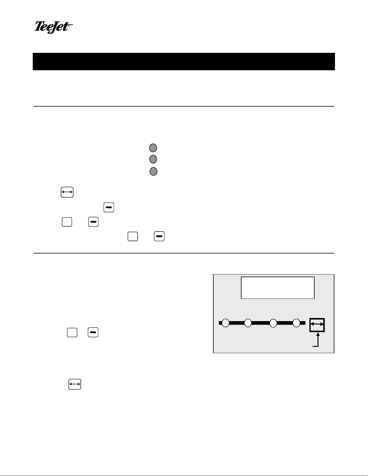
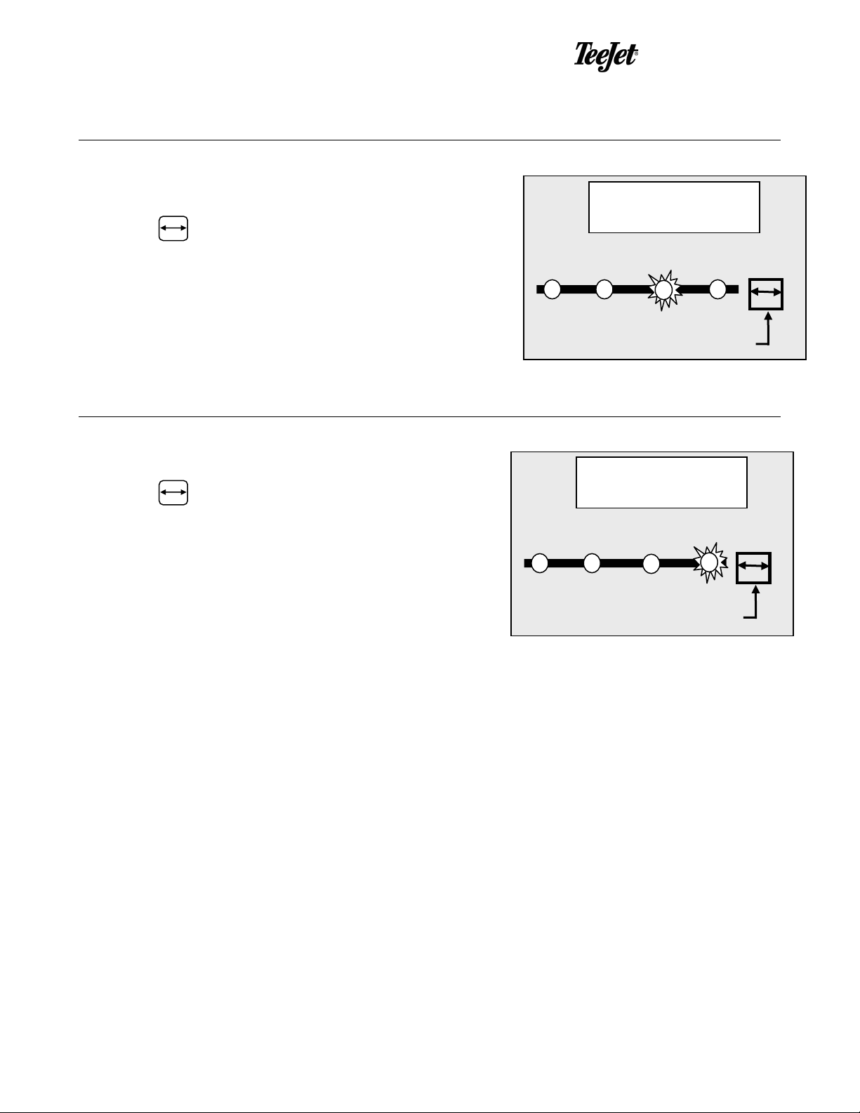
TARGET APPLICATION RATE DISPLAY
In this display the application rate in gallons per ton
(GPT) is shown. The target application rate will be
displayed any time the master boom switch is in the
off position (a "t" is on the display when the target
application rate is displayed). When the master
switch is on, no “t” is on the display and the actual
application rate is displayed.
+
Press the
application rate. This can be done before the
spraying operation begins with the Master
switch off or can be done on the go while spraying
in Auto mode.
Press the key to advance to the speed/rpm display.
or keys to select another target
tip
select
Inch
lbs/rot
GPA
GPT
Gal/min
@40 psi
SPEED
RPM
P/300ft
P/rot
PROGRAM MODE push 3 sec.
min
MPH
RPM
On
3 98-70028-R0
Page 4
834-P Sprayer Control TECHNOLOGIES
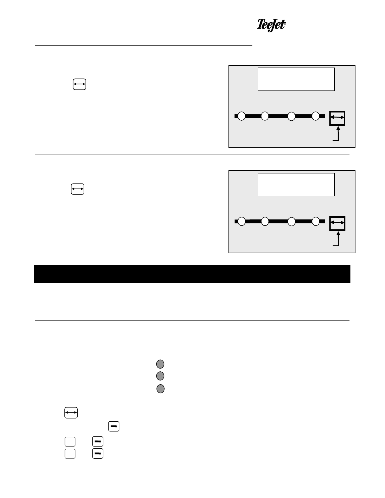
SPEED/RPM DISPLAY (GPT MODE)
In this display the shaft RPM is shown on the display.
Press the key to advance to the pressure display.
PRESSURE DISPLAY (GPT MODE)
In this display the pressure is shown in PSI.
Press the key to advance back to the rate display.
Normal Wor king Mode (GPA Mode)
tip
select
Inch
lbs/rot
tip
select
Inch
lbs/rot
GPA
GPT
Gal/min
@40 psi
GPA
GPT
Gal/min
@40 psi
SPEED
RPM
P/300ft
P/rot
PROGRAM MODE push 3 sec.
SPEED
RPM
P/300ft
P/rot
PROGRAM MODE push 3 sec.
min
min
MPH
RPM
MPH
RPM
On
On
Note: This section covers operation of the 834-P in Gallons Per Acre
mode. Instructions for Gallons Per Ton mode can be found on page 3.
INTRODUCTION
In the Gallons Per Acre (GPA) normal working mode, the display can show three different
pieces of information indicated by the LED’s below the display e.g.:
Application rate in GPA
Ground Speed
Pressure in PSI
Use of the keys during normal working mode is summarized as follows:
key is used to power ON and to select the information display
Auto/Man & key combination is used to power OFF (when not spraying)
+
98-70028-R0 4
and keys are used for changing the target application. In manual mode the
+
and keys drive the regulating valve to adjust pressure.
Page 5
TECHNOLOGIES 834-P Sprayer Control
TARGET APPLICATION RATE DISPLAY
In this display the application rate in gallons per acre
(GPA) is shown. The target application rate will be
displayed any time the master boom switch is in the
off position (a "t" is on the display when the target
application rate is displayed). When the master
switch is on, no “t” is on the display and the actual
application rate is displayed.
Press the + or keys to select another target
application rate. This can be done before the
spraying operation begins with the Master
switch off or can be done on the go while spraying
in Auto mode.
Press the key to advance to the speed display.
tip
select
Inch
lbs/rot
GPA
GPT
Gal/min
@40 psi
SPEED
RPM
P/300ft
P/rot
PROGRAM MODE push 3 sec.
MPH
RPM
On
5 98-70028-R0
Page 6
834-P Sprayer Control TECHNOLOGIES
SPEED/RPM DISPLAY (GPA MODE)
In this display the vehicle speed is shown in MPH.
Press the key to advance to the pressure display.
PRESSURE DISPLAY (GPA MODE)
In this display the pressure is shown in PSI.
Press the key to advance back to the rate display.
tip
select
Inch
lbs/rot
tip
select
Inch
lbs/rot
GPA
GPT
Gal/min
@40 psi
GPA
GPT
Gal/min
@40 psi
SPEED
RPM
P/300ft
P/rot
PROGRAM MODE push 3 sec.
SPEED
RPM
P/300ft
P/rot
PROGRAM MODE push 3 sec.
min
min
MPH
RPM
MPH
RPM
On
On
98-70028-R0 6
Page 7

TECHNOLOGIES 834-P Sprayer Control
Operating Instructions
THE SPRAYING OPERATION
Fill the sprayer tank and thoroughly mix the chemical(s). Your application rate should be
determined as well as the spray tip you will be using, with the sprayer data programmed into
the computer.
Switch the computer on by pressing the key on the display panel.
While spraying with the Master switch “ON”, you can scroll through the different displays
using the key until the information you want is on the display :
♦ actual application rate in GPT or GPA
♦ vehicle speed in MPH or shaft RPM
♦ pressure in PSI
Adjust the target application rate with the + and
Switch the Master boom switch to “ON” position to start spraying. Maintain your usual vehicle
speed for spraying. Use the + or keys to boost the application rate if needed. Small
changes in vehicle speed are compensated by the automatic rate controller while spraying in
Auto mode. Manual mode allows the operator to manually adjust system pressure by using
the + and
If for any reason you need to stop, turn the MASTER BOOM SWITCH to “OFF.”
keys.
keys.
Automatic Power Down
The TeeJet 834-P Sprayer Monitor has an automatic power down feature. With the Master
switch in the “OFF” position, the Console will automatically shut down after 10 minutes of no
inputs (when in normal working mode). This prevents possible battery drainage. Note that the
console will not power down while in programming mode.
You can also power down the controller by the following key combination: press
simultaneously the Auto and
with the Master switch OFF).
keys and the Console will power down immediately (only
Warning: Do not switch off the console by removing the main cable!
7 98-70028-R0
Page 8

834-P Sprayer Control TECHNOLOGIES
Alarms and Warnings
On the 834-P Console there are three LED's for indication of alarms or warnings.
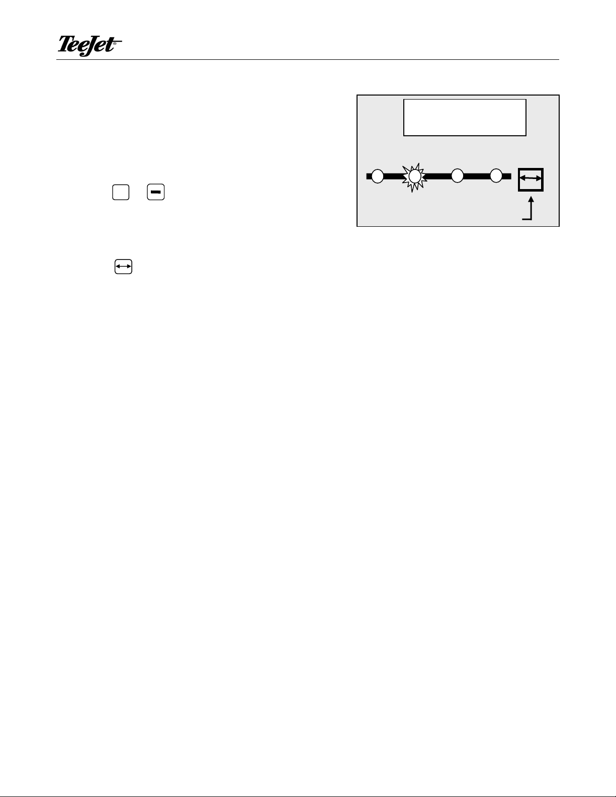
• The Speed alarm LED flashes when no speed pulses are
received during spraying (Master in the ON position). This
indicates that there is something wrong with the speed sensor
or that you are standing still while spraying.
Note: When this alarm is triggered, the display will
automatically switch the application display to view
speed (if not currently viewing speed) and the speed
display will flash off and on as well. This allows the
operator to immediately determine the location of the
problem.
• The Pressure alarm LED flashes when the signal from the
pressure sensor is absent while spraying (Master in
the ON position). This indicates that the pressure sensor is
not working properly, or that the connection with the sensor
has been lost.
Note: When this alarm is triggered, the display will
automatically switch the application display to view
pressure (if not currently viewing pressure) and
the pressure display will flash off and on as well.
This allows the operator to immediately determine
the location of the problem.
• The minimum RPM/MPH LED is lit when the programmed
minimum speed or RPM has been reached. When this LED is lit,
the pump has been switched off.
Speed
Pressure
MPH
min
RPM
Speed
Pressure
MPH
min
RPM
Speed
98-70028-R0 8
Pressure
MPH
min
RPM
Page 9

TECHNOLOGIES 834-P Sprayer Control
Programming Guidelines
Make sure that all hardware components are properly installed and tested. Before you start
the programming process you should first check if the console and all sensors are working
properly.
Important Preliminary Information
Before you begin, we recommend that you review the following Programming Guidelines that
control the programming process:
The key is used to power the console ON
Auto & simultaneous key combination is used to power OFF (Master boom switch
must be in the off position)
Holding key for 3 seconds is used to enter programming mode
The white text above the indicator LEDs on the front panel refers the the data displayed
in normal working mode. Look at the white colored text labels whil in normal operating
mode.
The gold text below the indicator LEDs on the front panel refers to the value being set in
programming mode. Look at the gold colored text labels while in programming mode.
Pressing the key saves the current parameter and advances to the next
programming step during programming mode
The value of a parameter is changed with the + and keys. Holding the + or
key changes the parameter rapidly.
9 98-70028-R0
Page 10

834-P Sprayer Control TECHNOLOGIES
Console Programming (GPT Mode)
To begin the programming process:
Be sure the Master boom switch is “OFF.”
Turn console “ON” by pressing the key. When the control console is turned on, the
software version will be displayed for approximately 5 seconds. At the same time all
LED’s will be ON.
The software version and serial number of the console will be needed when calling for
support. The serial number is located on a sticker on the back of the console.
tip
select
GPA
GPT
SPEED
RPM
On
Inch
lbs/rot
Gal/min
@40 psi
P/300ft
P/rot
min
MPH
RPM
PROGRAM MODE push 3 sec.
Example: the software version is Y1.04.
After a short time the console will change to the target application rate display.
tip
select
Inch
lbs/rot
GPA
GPT
Gal/min
@40 psi
SPEED
RPM
P/300ft
P/rot
PROGRAM MODE push 3 sec.
min
MPH
RPM
On
98-70028-R0 10
Page 11

TECHNOLOGIES 834-P Sprayer Control
System Setup Mode (GPT mode)
The System Setup Mode contains the programming steps that customize the controller to the
sprayer or sprayer components. These include calibration steps and parameters that, once
programmed, are not likely to change.
To enter the System Setup Mode:
First be sure that the console is ON (if not turn it on by pressing the key and wait
until the normal display is visible).
Ensure the Master boom switch is OFF.
Then press and hold the key for 3 seconds to enter the Program Mode.
OPERATING MODE
The 834-P can operate in either of two modes. They
are GPT (gallons per ton), used for pre-wetting
applications, or GPA (gallons per acre)used for
agricultural or anti-icing applications.
Use the + or
keys to adjust this value. Once
the correct mode has been selected, press
the key to advance to the next step. If
operating in GPA mode, skip ahead to page 14.
MINIMUM RPM
The 834-P can be set to automatically switch off the
flow of liquid when the salt/sand auger shaft slows
below a minimum speed. This feature prevents
liquid from being applied when the salt/sand
spreader is switched off.
+
Use the
or
shaft RPM below which the pre-wetting spray should
be switched off.
keys to adjust this value to the
tip
select
Inch
lbs/rot
tip
select
Inch
lbs/rot
GPA
GPT
Gal/min
@40 psi
GPA
GPT
Gal/min
@40 psi
SPEED
RPM
P/300ft
P/rot
PROGRAM MODE push 3 sec.
SPEED
RPM
P/300ft
P/rot
PROGRAM MODE push 3 sec.
min
min
MPH
RPM
MPH
RPM
On
On
11 98-70028-R0
Page 12

834-P Sprayer Control TECHNOLOGIES
SHAFT SENSOR CALIBRATION
The shaft speed sensor needs to be calibrated in order to provide the proper speed reading.
The value for this step is the number of pulses generated by the shaft speed sensor in one
revolution. For example, if the shaft speed sensor is mounted to sense the teeth of a
sprocket, enter the number of teeth on that sprocket.
SPRAY TIP CAPACITY
Enter the combined capacity of all nozzles on the system. This should be measured in
Gallons Per Minute at 40 PSI. These capacities can be obtained from the nozzle
manufacturer’s catalog..
+
Use the
press the key to advance to the next step.
Example: Two 8004 nozzles would have a combined capacity of .8 GPM at 40 PSI.
or
keys to adjust this value. Once the correct units have been selected,
POUNDS PER ROTATION
In order to apply liquid at a fixed proporation to the dry material being applied, the controller
must be able to associate the amount of dry material applied with each rotation of the shaft.
To determine this number, operate the dry spreader. Allow the shaft to turn several
revolutions and weight the material applied. Divide the total weight by the number of shaft
rotations to determine pounds per rotation (lbs/rot).
Auto-Calibration
This value can be determined by an automatic calibration sequence. To perform this
operation:
+
a) Push the
b) Press the + key to start calibration.
c) Dispense exactly 100 lbs of material, then press
controller will automatically calculate the number of lbs/rot.
d) Press select key to accept value and conclude programming.
This concludes the programming of your 834-P for prewetting applications. The target
application rate in Gallons per Ton (GPT) can be set any time the master switch is off by
pressing the + or
and keys simultaneously. The display will show a blinking CAL.
+
again to stop calibration. The
keys.
98-70028-R0 12
Page 13

TECHNOLOGIES 834-P Sprayer Control
Console Programming (GPA Mode)
To begin the programming process:
Be sure the Master boom switch is “OFF.”
Turn console “ON” by pressing the key. When the control console is turned on, the
software version will be displayed for approximately 5 seconds. At the same time all
LED’s will be ON.
The software version and serial number of the console will be needed when calling for
support. The serial number is located on a sticker on the back of the console.
tip
select
GPA
GPT
SPEED
RPM
On
Inch
lbs/rot
Gal/min
@40 psi
P/300ft
P/rot
min
MPH
RPM
PROGRAM MODE push 3 sec.
Example: the software version is Y1.04.
After a short time the console will change to the target application rate display.
tip
select
Inch
lbs/rot
GPA
GPT
Gal/min
@40 psi
SPEED
RPM
P/300ft
P/rot
PROGRAM MODE push 3 sec.
min
MPH
RPM
On
13 98-70028-R0
Page 14

834-P Sprayer Control TECHNOLOGIES
System Setup Mode (GPA mode)
The System Setup Mode contains the programming steps that customize the console to the
sprayer or sprayer components. These include calibration steps and parameters that, once
programmed, are not likely to change.
To enter the System Setup Mode:
First be sure that the console is ON (if not turn it on by pressing the key and wait
until the normal display is visible).
Ensure the Master boom switch is OFF.
Then press and hold the key for 3 seconds to enter the Program Mode.
OPERATING MODE
The 834-P can operate in either of two modes. They
are GPT (gallons per ton), used for pre-wetting
applications, or GPA (gallons per acre)used for
agricultural or anti-icing applications.
Use the + or
keys to adjust this value. Once
the correct mode has been selected, press
the key to advance to the next step. If
operating in GPT mode, see page 10.
MINIMUM MPH
The 834-P can be set to automatically switch off the
flow of liquid when the machine slows below a
minimum speed. This feature automatically prevents
liquid from being applied when the machine is
stopped.
tip
select
Inch
lbs/rot
tip
select
GPA
GPT
Gal/min
@40 psi
GPA
GPT
SPEED
RPM
P/300ft
P/rot
PROGRAM MODE push 3 sec.
SPEED
RPM
min
MPH
RPM
On
On
Use the + or
machine speed below which spray should be
switched off.
keys to adjust this value to the
Inch
lbs/rot
Gal/min
@40 psi
PROGRAM MODE push 3 sec.
98-70028-R0 14
P/300ft
P/rot
min
MPH
RPM
Page 15

TECHNOLOGIES 834-P Sprayer Control
SPEED SENSOR CALIBRATION
Default = 250 pulses/300ft
The speed sensor needs to be calibrated in order to
provide the proper speed reading. The value for this
step is the number of pulses generated by the speed
sensor in 300 feet. For example, if the speed sensor
is mounted to sense lug bolts on a sprayer wheel,
this value would reflect the number of bolts passing
the sensor over a 300 foot distance.
Auto Calibration
The speed sensor can be automatically calibrated
by driving 300 feet. The console will automatically
detect a RADAR sensor (if used).
To start the auto calibration procedure, press
simultaneously on the + and
display now will show CAL.
Now you have to drive to the starting point of the
keys. The
tip
select
Inch
lbs/rot
tip
select
Inch
lbs/rot
GPA
GPT
Gal/min
@40 psi
GPA
GPT
Gal/min
@40 psi
SPEED
RPM
P/300ft
P/rot
PROGRAM MODE push 3 sec.
SPEED
RPM
P/300ft
P/rot
min
MPH
RPM
min
MPH
RPM
On
On
300ft distance. Push the + key to start counting
speed pulses as you cross the start point.
Drive 300ft and press + again to stop the pulse
counting as you cross the finish point.
Note: During Auto Calibration the Man LED will flash.
The number now on the display is the number of
pulses corresponding to 300ft.
The auto calibration procedure can be escaped with
the key. The console will then return to the
previous calibration value.
Note: The auto speed calibration should be
repeated at least twice and an average of
the calibration numbers should be entered.
tip
select
Inch
lbs/rot
PROGRAM MODE push 3 sec.
GPA
GPT
Gal/min
@40 psi
SPEED
RPM
PROGRAM MODE push 3 sec.
P/300ft
P/rot
min
MPH
RPM
On
15 98-70028-R0
Page 16

834-P Sprayer Control TECHNOLOGIES
×
Radar
A radar speed sensor will be indicated with an "r" on
the display e.g.
The "r" will automatically appear during the auto
calibration process when the console has determined
that a radar is being used. When manually entering
Tip
select
GPA
MPH
On
a radar calibration number the "r" must be turned on
by pushing the Auto/Man key. With this key you can
toggle between radar or wheel sensor. The calibration
value itself is adjusted with the + and
keys.
tip spacing
(inch)
speed cal
(pulses/300ft.)
PROGRAM MODE push 3 sec.
density
Manual Calculation
To manually calculate the proper value for Wheel Speed Sensor pulses, you need to know
the circumference of the wheel to which the sensor is mounted. It can be measured by
marking the tire and measuring the distance covered as that mark makes one full revolution.
Then use the following formula:
58
4600,3
=
248
×
#600,3
rotationperPulses
..
=
ge
InchInnceCircumfereWheel
Use the + or keys to adjust the value. Press the key to validate the value and
advance to the next programming step.
Note: The wheel calibration should be repeated if you are changing to another wheel
diameter.
Simulated Speed
If you enter 0 in the speed calibration step, then the console always works with a simulated
speed. This simulated speed can be used to test out the sprayer at stand still.
The simulated speed feature allows you to check out the sprayer at a certain speed without
actually moving the sprayer. This can be done prior to any spraying activity. The simulated
speed value can be changed with the
display in normal working mode.
+
and keys when the speed is shown on the
98-70028-R0 16
Page 17

TECHNOLOGIES 834-P Sprayer Control
SPRAY TIP CAPACITY
Enter the combined capacity of all nozzles on the system. This should be measured in
Gallons Per Minute at 40 PSI. These capacities can be obtained from the nozzle
manufacturer’s catalog.
Use the
+
or
keys to adjust this value. Once the correct units have been selected,
press the key to advance to the next step.
Example: Two 8004 nozzles would have a combined capacity of .8 GPM at 40 PSI.
SWATH WIDTH
Enter the total swath width of the sprayer in inches.
Use the
correct units have been selected, press the key to
advance to the next step.
+
or
keys to adjust this value. Once the
tip
select
Inch
lbs/rot
GPA
GPT
Gal/min
@40 psi
SPEED
RPM
P/300ft
P/rot
PROGRAM MODE push 3 sec.
min
MPH
RPM
On
17 98-70028-R0
Page 18

834-P Sprayer Control TECHNOLOGIES
Midwest Technologies Illinois, LLC
2864 Old Rochester Road
Springfield, IL 62703
98-70028-R0 18
 Loading...