

Page 1
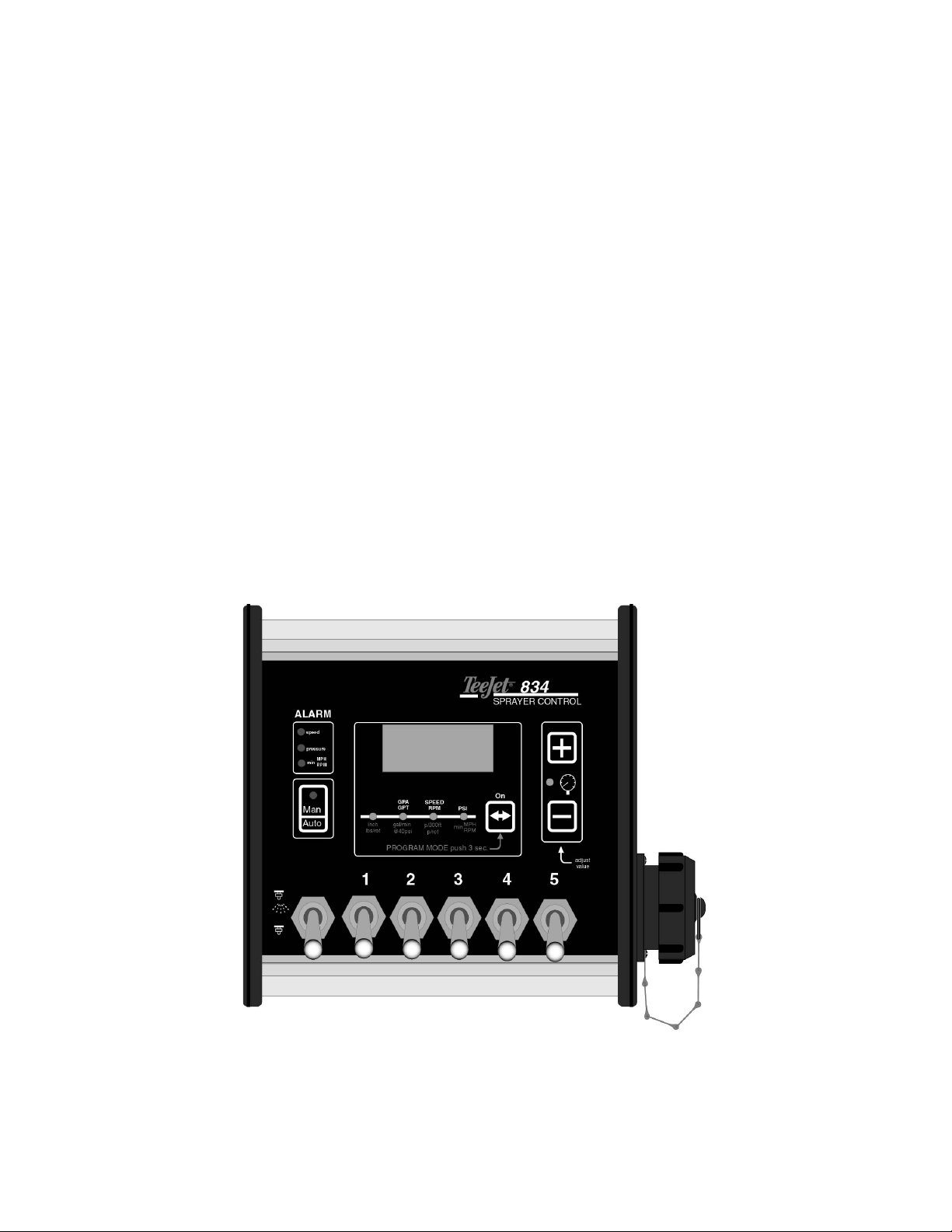
TeeJet
®
834
Sprayer Control
Programming and Operating Manual
U2.12
98-70004
R0
MI 834 Programming and Operating Manual 9/99 Page 1 of 15
Page 2

Table of Contents
Programming Guidelines________________________________________________________________ 3
Start _____________________________________________________________________________________ 4
System Setup Mode _____________________________________________________________________ 5
Density __________________________________________________________________________________5
Speed Sensor Calibration ___________________________________________________________________6
Auto Calibration__________________________________________________________________________6
Manual Calculation _______________________________________________________________________7
Simulated Speed _________________________________________________________________________7
Tip Spacing_______________________________________________________________________________8
Pressure Regulating Mode __________________________________________________________________8
Application Units __________________________________________________________________________8
Normal Working Mode___________________________________________________________________ 9
Introduction ______________________________________________________________________________9
Target Application Rate Display ______________________________________________________________ 9
Speed Display____________________________________________________________________________10
Pressure Display _________________________________________________________________________ 10
Tip Selection Display ______________________________________________________________________11
Operating Instructions _________________________________________________________________ 13
Sprayer Checkout_________________________________________________________________________13
The Spraying Operation____________________________________________________________________ 14
Automatic Power Down ________________________________________________________________ 14
Alarms and Warnings __________________________________________________________________ 15
MI 834 Programming and Operating Manual 9/99 Page 2 of 15
Page 3
Programming Guidelines
Make sure that all hardware components are properly installed and tested. Before you start
the programming process you should first check if the console and all sensors are working
properly.
Important Preliminary Information
Before you begin, we recommend that you review the following Programming Guidelines that
control the programming process:
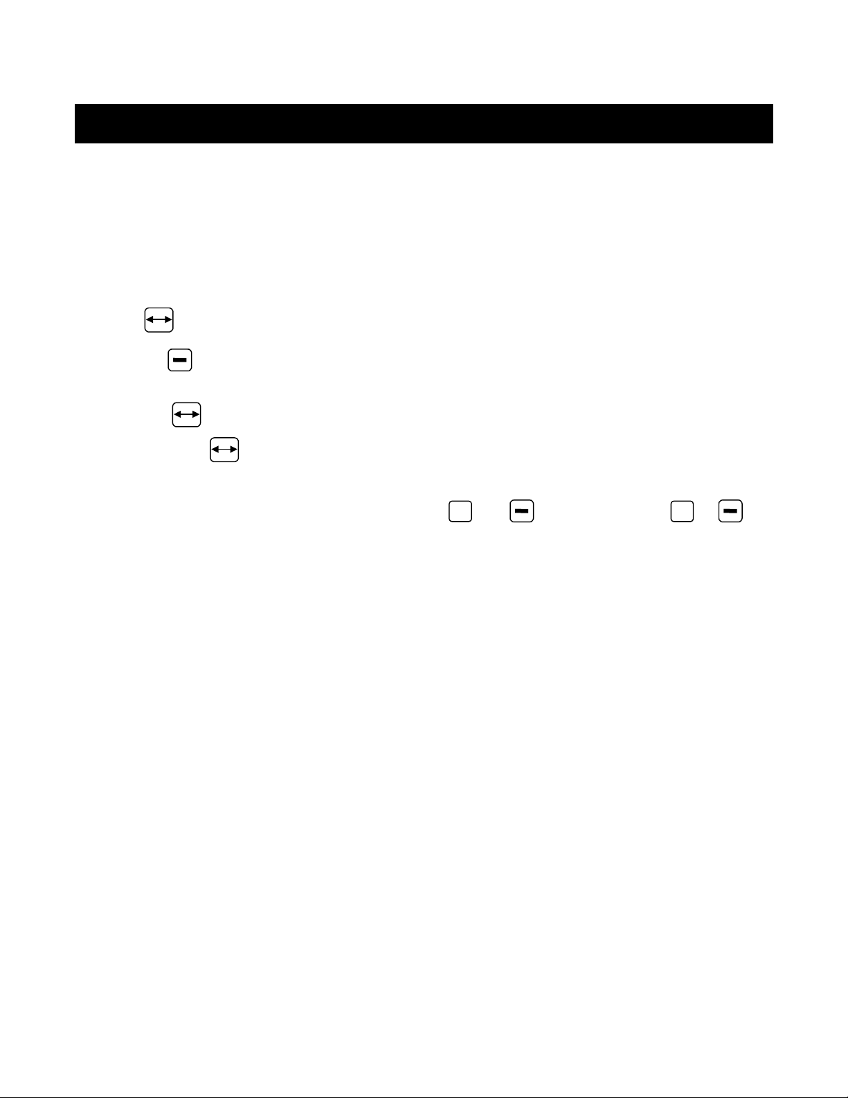
☛ The key is used to power the console ON
☛ Auto & simultaneous key combination is used to power OFF (Master boom switch
must be in the off position)
☛ Holding key for 3 seconds is used to enter programming mode
☛ Pressing the key saves the current parameter and advances to the next
programming step during programming mode
☛ The value of a parameter is changed with the
key changes the parameter rapidly.
+
and keys. Holding the + or
MI 834 Programming and Operating Manual 9/99 Page 3 of 15
Page 4
Start
To begin the programming process:
☛ Be sure the Master boom switch is “OFF.”
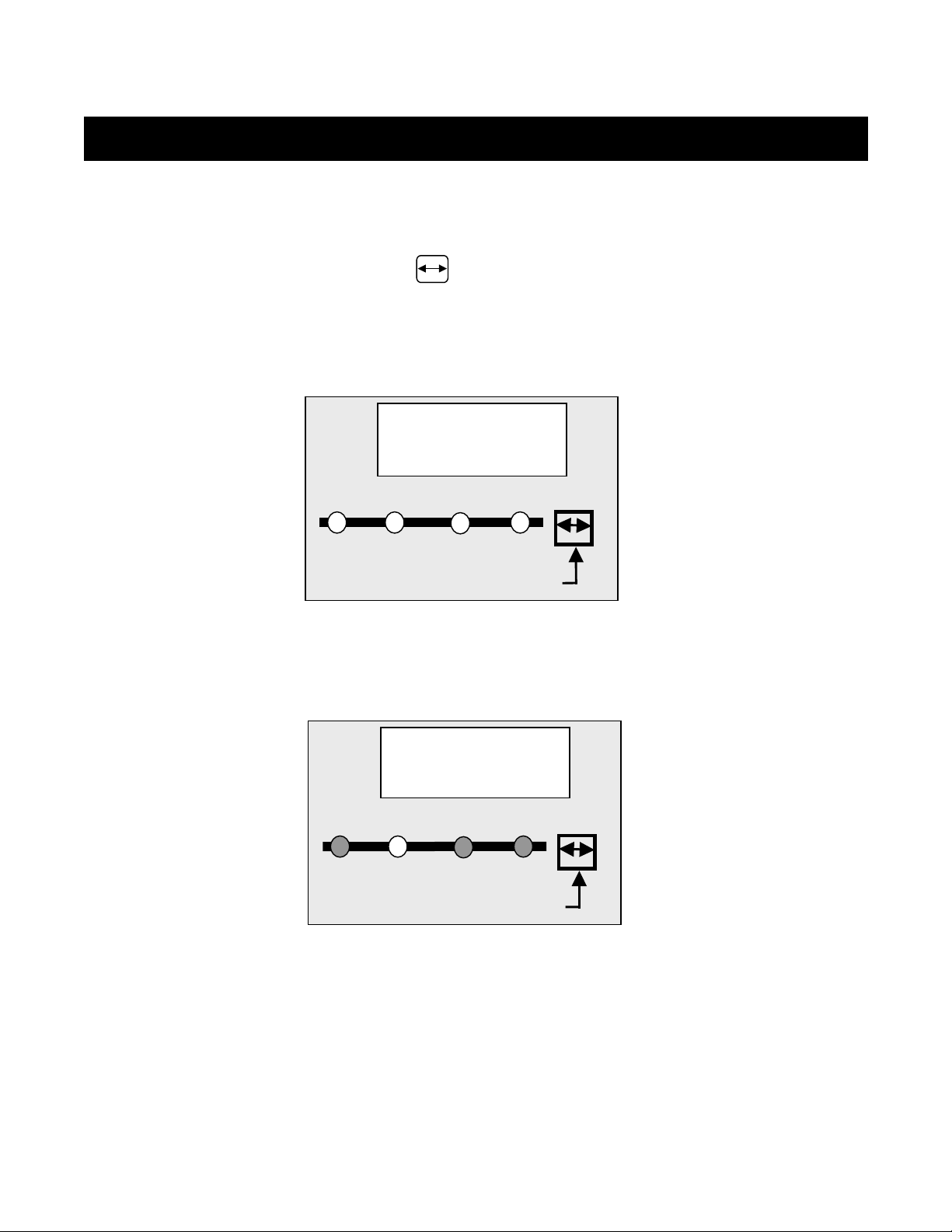
☛ Turn console “ON” by pressing the key. When the control console is turned on, the
software version will be displayed for approximately 5 seconds. At the same time all
LED’s will be ON.
The software version and serial number of the console will be needed when calling for
service support. The serial number is located on a sticker on the back of the console.
Tip
select
tip spacing
(inch)
U2.12
GPA
speed cal
(pulses/300ft.)
PROGRAM MODE push 3 sec.
On
density
Example: the software version is U2.12.
☛ After a short time the console will change to the target application rate display.
T20.0
Tip
select
tip spacing
(inch)
GPA
speed cal
(pulses/300ft.)
PROGRAM MODE push 3 sec.
density
On
MI 834 Programming and Operating Manual 9/99 Page 4 of 15
Page 5
System Setup Mode
The System Setup Mode contains the programming steps that customize the monitor to the
sprayer or sprayer components. These include calibration steps and parameters that, once
programmed, will likely never change.
To enter the System Setup Mode:
☛ First be sure that the console is ON (if not turn it on by pressing the key and wait
until the normal display is visible).
☛ Ensure the Master boom switch is OFF.
☛ Then press and hold the key for 3 seconds to enter the Program Mode.
D
ENSITY
Default = 1.00
If a substance other than water is being sprayed
or used as a carrier (e.g. liquid fertilizer), enter
the density of that fluid.
Weight of
Solution Per Gallon
7.0 lbs. 0.84
8.0 lbs. 0.96
8.34 lbs. - Water 1.00
10.0 lbs. 1.20
10.65 lbs. – 28% N 1.28
10.85 lbs. – 30% N 1.30
11.0 lbs. 1.32
12.0 lbs. 1.44
Liquid
Density
1.00
Tip
select
tip spacing
(inch)
GPA
speed cal
(pulses/300ft.)
PROGRAM MODE push 3 sec.
density
Note: If the solution that you
are using can not be found in
the chart at left, the Liquid
Density can be calculated as
follows:
Density = Weight of Solution
Weight of Water
On
14.0 lbs. 1.68
Use the + or
MI 834 Programming and Operating Manual 9/99 Page 5 of 15
keys to adjust this value. Once the correct units have been selected,
Page 6

press the key to advance to the next step.
S
PEED SENSOR CALIBRATION
Default = 250 pulses/300ft
The speed sensor needs to be calibrated in order
to provide the proper speed reading. The value
for this step is the number of pulses generated by
the speed sensor in 300 feet.
Auto Calibration
The speed sensor can be automatically calibrated
by driving 300ft. The console will automatically
detect a RADAR sensor (if used).
To start the auto calibration procedure, press
simultaneously on the + and keys. The
display now will show CAL.
Now you have to drive to the starting point of the
Tip
select
tip spacing
(inch)
Tip
select
tip spacing
(inch)
250
GPA
speed cal
(pulses/300ft.)
PROGRAM MODE push 3 sec.
cal
GPA
speed cal
(pulses/300ft.)
PROGRAM MODE push 3 sec.
On
density
On
density
300ft distance. Push the + key to start counting
speed pulses as you cross the start point.
Drive 300ft and press + again to stop the pulse
counting as you cross the finish point.
Note: During Auto Calibration the Man LED will flash
each time a pulse is recorded.
The number now on the display is the number of
pulses corresponding to 300ft.
The auto calibration procedure can be escaped with
the key. The console will then return to the
previous calibration value.
Note: The auto speed calibration should be
repeated at least twice and an average of
the calibration numbers should be entered.
Tip
select
tip spacing
(inch)
248
GPA
speed cal
(pulses/300ft.)
PROGRAM MODE push 3 sec.
On
density
MI 834 Programming and Operating Manual 9/99 Page 6 of 15
Page 7

Radar
A radar speed sensor will be indicated with an "r" on
the display e.g.
The "r" will automatically appear during the auto
calibration process when the console has determined
that a radar is being used. When manually entering
Tip
select
r10.0
GPA
On
a radar calibration number the "r" must be turned on
by pushing the Auto/Man key. With this key you can
toggle between radar or wheel sensor. The calibration
tip spacing
(inch)
speed cal
(pulses/300ft.)
PROGRAM MODE push 3 sec.
density
value itself is adjusted with the + and keys.
Manual Calculation
To manually calculate the proper value for Wheel Speed Sensor pulses, you need to know the
circumference of the wheel to which the sensor is mounted. It can be measured by marking the
tire and measuring the distance covered as that mark makes one full revolution.
Then use the following formula:
#600,3
WheelOnMagnets
..
=×ge
InchInnceCircumfereWheel
58
×
4600,3
248
=
Use the + or keys to adjust the value. Press the key to validate the value and
advance to the next programming step.
Note: The wheel calibration should be repeated if you are changing to another wheel diameter.
Simulated Speed
If you enter 0 in the speed calibration step, then the console always works with a simulated
speed. This simulated speed can be used to test out the sprayer at stand still.
The simulated speed feature allows you to check out the sprayer at a certain speed without
actually moving the sprayer. This can be done prior to any spraying activity. The simulated speed
+
value can be changed with the
normal working mode.
and keys when the speed is shown on the display in
MI 834 Programming and Operating Manual 9/99 Page 7 of 15
Page 8

T
IP SPACING
Default = 20 inches
Use the + or
Once the correct units have been selected,
keys to adjust this value.
Tip
select
GPA
On
press the key to advance to the next step.
The value shown is represented in inches.
tip spacing
(inch)
speed cal
(pulses/300ft.)
PROGRAM MODE push 3 sec.
density
P
RESSURE REGULATING MODE
Default = byP
The default value "byP" indicates that the pressure
regulating valve is plumbed in a bypass line. If the
byp
Tip
select
GPA
On
default value is correct, press the key.
Use the + or
keys to change the
tip spacing
(inch)
speed cal
(pulses/300ft.)
PROGRAM MODE push 3 sec.
density
value to throttle (tHr) mode if needed.
Note: This setting must match the actual plumbed mode of the regulating valve.
Changing this setting will only reverse the polarity to the valve, it will not effect the
physical operation of the valve. Refer to the plubing diagrams in the Plumbing and
Installation Manual supplied with this unit.
A
PPLICATION UNITS
Default = US
Select the application units to be used for
regulation. If you will be using US units (GPA)
Tip
select
US
GPA
On
Press the key to advance to the next
step. If you will be using trf units (G/1000 ft2)
use the + or
keys to select this value.
tip spacing
(inch)
speed cal
(pulses/300ft.)
PROGRAM MODE push 3 sec.
density
Once the correct units have been selected,
press the key to save this parameter and to return to the normal working mode.
MI 834 Programming and Operating Manual 9/99 Page 8 of 15
Page 9

Normal Working Mode
I
NTRODUCTION
In normal working mode, the display can show four different pieces of information indicated by
the LED’s below the display e.g.:
Tip selection
Application rate in GPA (G/1000ft2)
Speed in MPH
Pressure in PSI
The usage of the keys during normal working mode is summarized as follows:
☛
key is used to power ON and to move to another information display
☛
Auto/Man & key combination is used to power OFF (when not spraying)
+
☛
☛
T
ARGET APPLICATION RATE DISPLAY
and keys are used for changing the target application rate or for changing the tip.
In manual mode the + and keys drive the regulating valve to adjust pressure.
In this display the application rate in GPA (G/1000ft2)
is shown. When a "t" is shown then the target
application rate is displayed, otherwise the current
application rate is shown. The target application rate
Tip
select
T20.0
GPA
On
will be displayed any time the master boom switch is
in the off position.
Press the + or keys to select another target
application rate. This can be done before the
tip spacing
(inch)
speed cal
(pulses/300ft.)
PROGRAM MODE push 3 sec.
density
spraying operation begins with the Master
switch off or can be done on the go while spraying
in Auto mode.
Press the key to advance to the speed display.
MI 834 Programming and Operating Manual 9/99 Page 9 of 15
Page 10

S
PEED DISPLAY
In this display the speed is shown in MPH.
Press the key to advance to the pressure display.
Tip
select
3.5
GPA
On
P
RESSURE DISPLAY
In this display the pressure is shown in PSI.
Press the key to advance to the tip selection
display.
tip spacing
(inch)
Tip
select
tip spacing
(inch)
speed cal
(pulses/300ft.)
PROGRAM MODE push 3 sec.
42
GPA
speed cal
(pulses/300ft.)
PROGRAM MODE push 3 sec.
density
density
On
MI 834 Programming and Operating Manual 9/99 Page 10 of 15
Page 11

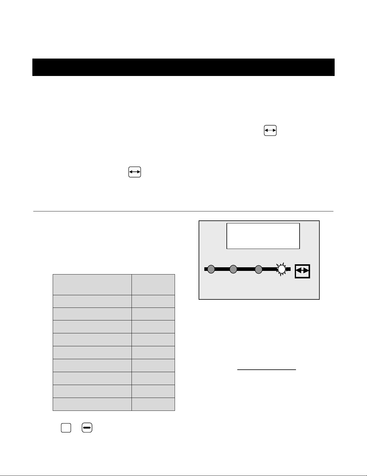
T
IP SELECTION DISPLAY
This display is the tip selection display. On the display
the two last digits of the VisiFlo color coded tip are
shown, e.g. an XR11004 corresponds with _04.
(See Table Below) The last selection _P is a
programmable selection in case the tips being used
do not match one of the preprogrammed flow rates.
See the following page for programming instructions
on the _P selection.
Press the + or keys to select another tip.
Note: The tip size can only be changed with the
Master switch in the OFF position and with the
console in Auto mode
Tip
select
tip spacing
(inch)
GPA
speed cal
(pulses/300ft.)
PROGRAM MODE push 3 sec.
density
On
TeeJet VisiFlo
Tip Color
Example
TeeJet Tip
Flow Rate In
US GPM @ 40
PSI
TeeJet 834 Tip
Size Designation
Orange XR11001VS 0.10 _01
Green DG80015VP 0.15 _01.5
Yellow TJ60-6502VS 0.20 _02
Turquoise AI110025-VS 0.25 _02.5
Blue TT11003VP 0.30 _03
Red AI11004-VS 0.40 _04
Brown TT11005VP 0.50 _05
Gray TP11006VS 0.60 _06
White XR8008VP 0.80 _08
Lt. Blue TK-VS5 1.00 _10
Lt. Green TF-VS7.5 1.50 _15
MI 834 Programming and Operating Manual 9/99 Page 11 of 15
Page 12

Programmable Tip
As mentioned above the _P section of the Tip
Selection Display can be programmed to match
the flow rate of the tips on the sprayer if they do
not fall into one of the categories listed above.
To access the programmable section, while viewing
the _P display, simulataneously press the
Auto/Man and keys for 3 seconds.
The display will then display a flashing flow rate
represented in US GPM at 40 PSI. The Tip Select
LED will also be flashing. Use the + and
keys to adjust this value so that it matches the flow
rate of one of your tips in GPM at 40 PSI.
Tip
select
tip spacing
(inch)
Tip
select
tip spacing
(inch)
_p
GPA
speed cal
(pulses/300ft.)
PROGRAM MODE push 3 sec.
0.40
GPA
speed cal
(pulses/300ft.)
PROGRAM MODE push 3 sec.
On
density
On
density
Note: It is critical that this flow rate be referenced at 40 PSI for the controller to regulate
the application rate correctly.
Press the key to save the _P value and return to the Tip Select display.
MI 834 Programming and Operating Manual 9/99 Page 12 of 15
Page 13

Operating Instructions
S
PRAYER CHECKOUT
Before spraying check all connections related to the Sprayer Control assembly. Particular
attention should be given to the speed sensor to be sure the sensor and bolts or magnets are inline, and properly secured or that the radar is installed at the proper height and correct angle.
Very important: Whenever you are working around a sprayer or farm chemicals, be sure to
Partially fill the sprayer tank with water to flush the system and to make a visual check of the
spray tips to be sure all tips are delivering a good spray pattern.
Follow these steps, in sequence, being sure the Master Boom Switch is in its “OFF” position:
wear protective clothing and eyewear.
☛ Be sure the tank shut-off valve is open.
☛ Start the engine, engage pump, and set the rpm to that which will be used when spraying.
☛ Switch the computer on by pressing the On key on the display panel.
☛ Turn “ON” the toggle switches for each of the spray booms on your sprayer.
☛ Ensure that the Auto/Man key indicates manual mode.
☛ Now, toggle the Master switch to “on.”
+
☛ Adjust the pressure with the
At this point, the sprayer will be activated and spray tip performance can be visually checked.
The + and
Note: Pressing the
the
Regulating Mode step in the Programming Mode.
To stop spraying, toggle the Master switch to “OFF”.
The above steps provide a quick way to check-out your sprayer and computerized control
system.
key should decrease pressure. If this is reversed, check the Pressure
keys can be used to raise or lower your spraying pressure.
+
key in manual mode should increase the pressure. Pressing
or
keys.
MI 834 Programming and Operating Manual 9/99 Page 13 of 15
Page 14

T
HE SPRAYING OPERATION
You have filled the sprayer tank and have thoroughly mixed the chemical(s). Your application
rate has been determined as well as the spray tip you will be using, with the sprayer data
programmed into the computer.
☛ Switch the computer on by pressing the key on the display panel.
☛ Toggle the boom switches to their “ON” position, for each of the booms on your sprayer.
☛ Take note of the “numbered” booms on each side of the sprayer, so that the appropriate
boom can be toggled “OFF” as necessary.
☛ While spraying with the Master switch “ON”, you can scroll through the different displays
using the key until the information you want is on the display :
♦ actual application rate in GPA (G/1000ft2)
♦ vehicle speed in MPH
♦ pressure in PSI
♦ tip being used
☛ Adjust the target application rate with the
+
and
keys.
As you enter the field to the point where you will begin spraying, turn the Master boom switch to
“ON” position. This will activate the spraying operation. Maintain your usual vehicle speed for
spraying. Use the + or keys to boost the application rate if needed. Small changes in
vehicle speed are compensated by the automatic rate controller while spraying in Auto mode.
If for any reason you need to stop, turn the MASTER BOOM SWITCH to “OFF.”
Automatic Power Down
The TeeJet 834 Sprayer Monitor has an automatic power down feature. With the Master switch
in the “OFF” position, the Console will automatically shut down after 10 minutes of no inputs
(when in normal working mode). This prevents possible battery drainage.
You can also power down the controller by the following key combination: press simultaneously
the Auto and keys and the Console will power down immediately (only with the Master switch
OFF).
ARNING
W
O NOT SWITCH OFF THE CONSOLE BY REMOVING THE MAIN CABLE
: D
!
MI 834 Programming and Operating Manual 9/99 Page 14 of 15
Page 15

Alarms and Warnings
On the 834 Console there are three LED's for indication of alarms or warnings.
• The Speed alarm LED flashes when no speed pulses are
received during spraying (Master in the ON position). This
indicates that there is something wrong with the speed sensor
or that you are standing still while spraying.
Note: When this alarm is triggered, the display will
automatically switch the application display to view
speed (if not currently viewing speed) and the speed
display will flash off and on as well. This allows the
operator to immediately determine the location of the
problem.
• The Press alarm LED flashes when the signal from the
pressure sensor drops below 4mA while spraying (Master in
the ON position). This indicates that the pressure sensor is
not working properly.
Note: When this alarm is triggered, the display will
automatically switch the application display to view
pressure (if not currently viewing pressure) and
the pressure display will flash off and on as well.
This allows the operator to immediately determine
the location of the problem.
• The Density LED is a warning LED and it will be lit when the
density selected in the programming mode is different from 1.00
(e.g. the density of water). This LED warns the user that
the console is working with a density factor different from 1.00.
Speed
alarm
Press.
alarm
Density
Speed
alarm
Press.
alarm
Density
Speed
alarm
Press.
alarm
MI 834 Programming and Operating Manual 9/99 Page 15 of 15
Density
 Loading...