

Page 1
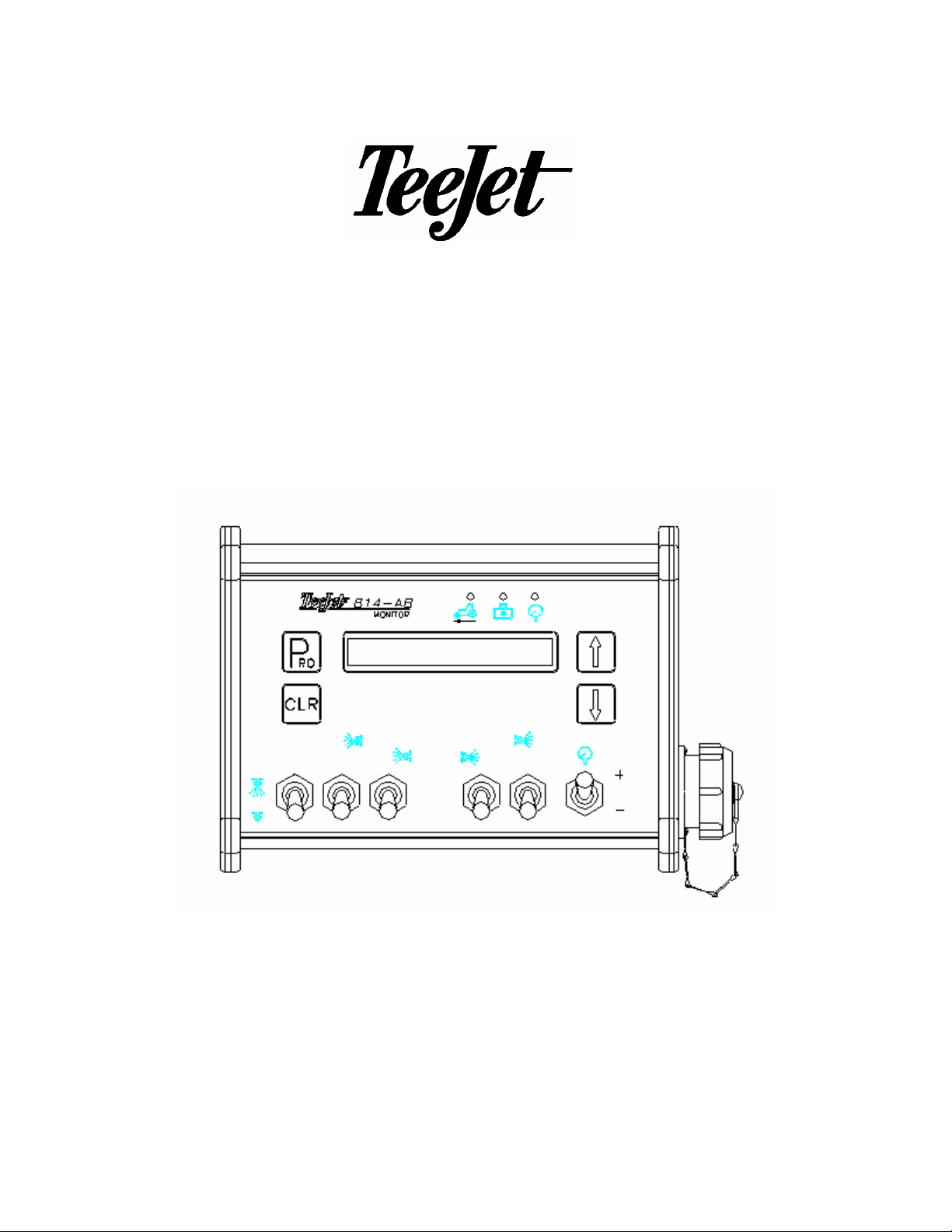
814-AB
Airblast Sprayer Monitor
Programming and Operating Manual
(v 2.10A)
98-70012-R0
814-AB Sprayer Monitor Programming and Operating Manual US 9/98 Page 1 of 15
Page 2

Table of Contents
Programming Guidelines________________________________________________________________ 3
Start _____________________________________________________________________________________ 4
Adjusting The Working Width ________________________________________________________________ 4
System Setup Mode_____________________________________________________________________ 5
Selecting Units_____________________________________________________________________________ 5
Speed Sensor Calibration____________________________________________________________________ 5
Manual Calculation ________________________________________________________________________ 6
Auto Calibration __________________________________________________________________________ 6
Simulated Speed__________________________________________________________________________ 7
Flow Meter Calibration ______________________________________________________________________ 7
Pressure sensor calibration __________________________________________________________________ 8
Step 1 __________________________________________________________________________________ 8
Step 2 __________________________________________________________________________________ 8
Completing the System Setup Mode ___________________________________________________________ 8
Normal Monitor Mode ___________________________________________________________________ 9
Introduction _______________________________________________________________________________ 9
Working Width _____________________________________________________________________________ 9
Changing the Working Width _______________________________________________________________ 10
Speed and Application Rate _________________________________________________________________ 10
Application Rate and Pressure_______________________________________________________________ 10
Flow Rate and Pressure ____________________________________________________________________ 10
Sprayed Area and Sprayed Volume ___________________________________________________________ 11
Operating Instructions_________________________________________________________________ 12
Sprayer Checkout _________________________________________________________________________ 12
The Spraying Operation ____________________________________________________________________ 12
Sensor Monitors________________________________________________________________________ 13
Automatic Power Down________________________________________________________________ 13
Appendix A: Overview of Monitor Displays ____________________________________________ 14
Appendix B: Overview of Programming Steps_________________________________________ 15
814-AB Sprayer Monitor Programming and Operating Manual US 9/98 Page 2 of 15
Page 3

Programming Guidelines
Make sure that all hardware components are properly installed and tested. Before you start
the programming process you should first check if the console and all sensors are working
properly.
Important Preliminary Information
Before you begin, we recommend that you review the following Programming Guidelines that
control the programming process:
☛ The Pro key is used for power ON
☛ Clr & Down key combination is used to power OFF (when not spraying)
☛ Holding Pro key for 3 seconds is used to enter and/or exit the programming mode
☛ Shortly pressing the Pro key once while in the programming mode saves the current
parameter and advances to the next programming step
☛ Shortly pressing the Clr key restores the parameter with the default value
☛ Holding the Clr key restores the parameter with its minimum value (mostly zero)
☛ The value of a parameter is changed with the Up and Down keys. Holding the Up or
Down key changes the parameter rapidly.
☛ Pressing the Pro key once while displaying the working width will allow the working width
to be adjusted. Once adjusted, pressing the Pro key again will return to the normal
operating mode.
814-AB Sprayer Monitor Programming and Operating Manual US 9/98 Page 3 of 15
Page 4

Start
To begin the programming process:
☛ Read above for programming tips.
☛ Be sure the Master switch is “OFF.”
☛ Turn console “ON” by pressing the Pro key. When the Control Console is turned on, the
software version will be displayed for approximately 5 seconds. The software version and
serial number of the console will be needed when calling for service support. The serial
number is located on a sticker on the back of the console.
814-AB US V2.10A
Example: the 814-AB airblast monitor is working in US units and the software version is
V2.10A.
☛ After a short time the console will change to the normal monitor mode. The first monitored
value is the working width.
10.0 ft
ADJUSTING THE WORKING WIDTH
Default = 10 ft. (3 m )
10.0 ft
➽ While in the normal monitoring mode, the display selected must be the working width.
➽ Be sure that the Master switch is in the OFF position.
➽ Then press the Pro key once.
10.0 ft <-O->
The working width display will then be flashing. The value can now be adjusted using the Up
and Down keys.
Once the value has been adjusted, return to the normal monitoring mode by pressing the Pro
key once.
814-AB Sprayer Monitor Programming and Operating Manual US 9/98 Page 4 of 15
Page 5

System Setup Mode
The System Setup Mode contains the programming steps that customize the monitor to the
sprayer or sprayer components. These include calibration steps and parameters that, once
programmed, will likely never change. An overview of all programming steps is shown in
“Appendix B: Overview of Programming Steps”.
To enter the System Setup Mode:
☛ First be sure that the console is ON (if not turn it on by pressing the Pro key and wait until
the normal display is visible).
☛ Check if the Master switch is OFF
☛ Then press and hold the Pro key for 3 seconds to enter the System Setup Mode.
SELECTING UNITS
Default = US
>US units
Select the units that the monitor will be operating in using the Up or Down keys. Select US
units for English measurement units or SI units for metric measurement units.
P
Depress the
RO
key to accept the value and advance to the next program step.
SPEED SENSOR CALIBRATION
Default = 250 pulses/300 feet (100 meters)
>250 puls/300ft
The speed sensor needs to be calibrated in order to provide the proper speed and area
readings. The value for this step is the number of pulses generated by the speed sensor in
300 ft (100 meters).
814-AB Sprayer Monitor Programming and Operating Manual US 9/98 Page 5 of 15
Page 6
Manual Calculation
To manually calculate the proper value for Wheel Speed Sensor pulses, you need to know
the circumference of the wheel to which the sensor is mounted. It can be measured by
marking the tire and measuring the distance covered as that mark makes one full revolution.
Then use the following formula:
#600,3
Use the Up or Down keys to adjust the value. Press the Pro key to validate the value and
advance to the next programming step.
Note: The wheel calibration should be repeated if you are changing to another wheel
diameter. If a radar calibration number is to be entered manually, the Clr key must be
pressed so that the "r" is displayed with the calibration number (see below).
WheelMagnetsOn
..
=×ge
InchesInnceCircumfereWheel
30
×
4600,3
=
480
Auto Calibration
The speed sensor can be automatically calibrated by driving 300ft. The console will
automatically detect a RADAR sensor (if used).
To start the auto calibration procedure, press simultaneously on the Up and Down keys.
The display now will show :
Start auto cal
Now you have to drive to the starting point of the 300ft distance. Push the Up key to start
counting speed pulses as you cross the start point. Drive 300ft and press the Up key again to
stop the pulse counting.
Drive300ft 176
Note: During the pulse counting the Speed Indication LED will be flashing.
Press the Up key when crossing the end point of the 300ft course. The number now on the
display is the number of pulses corresponding to 300ft.
223 puls/300ft
P
Depress the
814-AB Sprayer Monitor Programming and Operating Manual US 9/98 Page 6 of 15
RO
key to accept the value and advance to the next program step.
Page 7

A radar speed sensor will be indicated with an "r" on the display e.g.
Drive300ft r 11
The "r" will automatically appear during the auto calibration process when the console has
determined that a radar is being used. When manually entering a radar calibration number
the "r" must be turned on by pushing the Clr key. With this key you can toggle between
radar or wheel sensor. The calibration value itself is adjusted with the Up and Down keys.
>r12.4puls/300ft
The auto calibration procedure can be escaped with the Pro key. The console will then return
to the previous calibration value.
Note: The auto speed calibration should be repeated at least twice and an average of
the calibration numbers should be entered.
Simulated Speed
If you enter 0 in this programming step, then the console always shows a simulated speed of
6 mph. This can be used to test out the sprayer at stand still. The simulated speed feature
allows you to check out the sprayer at a certain speed without actually moving the sprayer.
This can be done prior to any spraying activity.
P
Depress the
RO
key to accept the flow meter value and advance to the next program step.
FLOW METER CALIBRATION
Default = 650 pulses/liter
> 650 puls/l
First, locate the factory calibrated Flow Meter pulse rate tag on the Flow Meter. If this varies
from the default value of the console, use the Up and Down keys to modify the value.
Note: The Flow Meter Calibration number will always be expressed in
pulses/liter. The monitor will automatically make the necessary
conversion if operating in US units.
P
Depress the
RO
key to accept the flow meter value and advance to the next program step.
814-AB Sprayer Monitor Programming and Operating Manual US 9/98 Page 7 of 15
Page 8

PRESSURE SENSOR CALIBRATION
If you don’t have a pressure sensor connected to your system, you may skip this step. You
only have to program the maximum pressure to zero in step 2.
If a pressure sensor is connected, it is calibrated with two programming steps. The first step
calibrates the sensor at 0 PSI (bar), while the second step calibrates the maximum pressure
of the sensor. The sensor can only be a 4 to 20 mA or 0 to 20 mA type.
Step 1
Default = 4.0 mA
In the first step the number of mA corresponding to 0 psi must be entered.
Use the Up and Down keys to change the value. If a 4-20 mA sensor is being used, 4 mA
would represent 0 PSI (bar) and should be entered here. If a 0-20 mA sensor is used, 0 mA
would represent 0 PSI (bar).
>4.0 mA 0.0 Psi
Press the Pro key to save this parameter and to advance to the next programming step.
Step 2
Default = 145 PSI (10 bar)
The second pressure calibration step specifies the maximum rated pressure of the sensor at
20mA. If no pressure sensor is connected then zero must be entered in this step.
Use the Up and Down keys to change the value.
>145 Psi 20 mA
Press the Pro key to save this parameter and to advance to the next programming step.
COMPLETING THE SYSTEM SETUP MODE
When you have completed the last calibration or programming step, you have completed the
System Setup Mode.
NOW, PRESS AND HOLD THE Pro KEY FOR THREE SECONDS AND THE CONSOLE
WILL RETURN TO THE NORMAL MONITOR MODE.
Note: For your protection, the Console will not automatically power down while in the
System Setup Mode. You must exit properly as described above to enable the
auto power down feature.
Note: Cutting the power to the controller while in the System Setup Mode will not save
any changes made into the computer’s memory.
814-AB Sprayer Monitor Programming and Operating Manual US 9/98 Page 8 of 15
Page 9

Normal Monitor Mode
INTRODUCTION
The monitor mode is the normal working mode of the Console after power up.
The screen shows one or two values at the same time (one on the left and/or one on the right
hand side). The displayed value can be recognized by the units displayed after the value [e.g.
the speed value is shown in MPH (km/h) units].
The usage of the keys during monitoring is summarized as follows:
☛ Pro key is used to power ON
☛ Clr & Down key combination is used to power OFF (when not spraying)
☛ Up and Down arrow keys are used for scrolling through the list of display information
☛ Holding Clr key is used to clear counter: Ac, Gal (Ha,l)
In the following, the different monitor displays will be described in more detail. An overview is
given in “Appendix A: Overview of Monitor Displays”.
WORKING WIDTH
The working width for an airblast sprayer is defined as the distance between the tree rows.
This distance is used for calculating the application rate and for making area measurements.
In the display the working width value is shown on the left hand side together with an arrow
symbol on the right hand side. The arrow symbol represents visually which sections are open
or closed. When the Master switch is OFF, only the total working width value is shown with no
arrow symbol.
10.0 ft
The current active working width depends on which sections are closed and whether or not
the master switch is turned off. When there is at least one section active on both sides (left
and right) then the active width is the total width. When all sections on one side are closed
then the active width is half of the total width (provided that there is at least one section active
on the other side).
Both sides (left and right) are active:
10.0 ft <-O->
Only left hand side is active:
5.0 ft <-O
814-AB Sprayer Monitor Programming and Operating Manual US 9/98 Page 9 of 15
Page 10

Only right hand side is active:
5.0 ft O->
Press the Up or Down key to select another display.
Changing the Working Width
The working width (distance between the trees) can quickly be changed by pressing the Pro
key when the width is displayed. The following screen will be shown:
> 10.0 ft <--->
The width number will be flashing and can now be changed with the Up and Down keys.
Pressing Pro again after the value is entered will save the new working width and the console
returns to the steady working width screen.
SPEED AND APPLICATION RATE
The next monitor display is the speed and application rate display. On the left the current
speed is shown in MPH (km/h) and on the right hand side the current dose rate in GPA (l/ha)
is shown. When the Master switch is switched off, the application rate shown is zero.
5.0 mph 50 Gpa
Press the Up or Down key to select another display.
APPLICATION RATE AND PRESSURE
In this display the application rate in GPA (l/ha) and the pressure in PSI (bar) are shown.
The pressure is only shown when there is a pressure sensor installed.
20 Gpa 30 PSI
Press the Up or Down key to select another display.
FLOW RATE AND PRESSURE
In this display flow in GPM (l/min) and the pressure in PSI (bar) is shown. The pressure are
only shown when there is a pressure sensor installed.
10.2 GPM 25 PSI
Press the Up or Down key to select another display.
814-AB Sprayer Monitor Programming and Operating Manual US 9/98 Page 10 of 15
Page 11

SPRAYED AREA AND SPRAYED VOLUME
In this display the area and volume counters are shown. The area is measured in Ac (Ha) and
the volume is measured in Gal (L). The counters can be reset to zero by pressing and holding
the Clr key until the values are reset to zero. This can only be done when there is no spraying
activity and the Master switch is OFF.
0.000 Ac 0 Gal
Press the Up or Down key to select another display.
814-AB Sprayer Monitor Programming and Operating Manual US 9/98 Page 11 of 15
Page 12

Operating Instructions
SPRAYER CHECKOUT
Before spraying check all connections related to the Sprayer Control assembly. Particular
attention should be given to the speed sensor to be sure the sensor and bolts or magnets are
in-line, and properly secured.
Very important: Whenever you are working around a sprayer or farm chemicals, be
sure to wear protective clothing and eyewear.
Partially fill the sprayer tank with water to flush the system and make a visual check of the
spray tips to be sure all tips are delivering a good spray pattern.
Follow these steps, in sequence, being sure the Master Switch is in its “OFF” position:
☛ Be sure the tank shut-off valve is open.
☛ Start the engine, engage pump, and set the rpm to that which will be used when spraying.
☛ Switch the computer on by depressing the Pro key on the display panel.
☛ Turn “ON” the toggle switches for each of the spray booms on your sprayer.
☛ Now, toggle the Master switch to “on.”
☛ Adjust the pressure with the +/- switch.
At this point, the sprayer will be activated and spray tip performance can be visually checked.
The +/- switch can be used to raise or lower your spraying pressure. To stop spraying, toggle
the Master switch to “OFF”.
The above steps provide a quick way to checkout your sprayer and computerized monitor
system.
THE SPRAYING OPERATION
You have filled the sprayer tank and have thoroughly mixed the chemical(s). Your application
rate has been determined as well as the spray tip you will be using, with the sprayer data
programmed into the computer.
☛ Switch the computer on by depressing the Pro key on the display panel.
☛ Toggle the boom switches to their “ON” position, for each of the booms on your sprayer.
☛ Take note of the “numbered” booms on each side of the sprayer, so that the appropriate
boom can be toggled “OFF” as necessary.
814-AB Sprayer Monitor Programming and Operating Manual US 9/98 Page 12 of 15
Page 13

☛ While spraying with the Master switch “ON”, you can scroll through the different displays
until the information you want is on the display :
♦ actual working width in FT(m)
♦ actual application rate in GPA (l/ha)
♦ vehicle speed in MPH (km/h)
♦ pressure in PSI (bar)
♦ application area covered in Acres (hectares)
♦ total volume applied in Gallons (liters)
☛ Adjust the pressure and target application rate with the +/- switch.
As you enter the field to the point where you will begin spraying, turn the Master switch to
“ON” position. This will activate the spraying operation. Maintain your usual vehicle speed for
spraying. Use the +/- key to maintain the application rate.
If for any reason you need to stop, turn the MASTER SWITCH to “OFF.”
Sensor Monitors
Speed, Flow and Pressure sensor monitors are located just above the monitor display. Each
time a sensor receives a pulse, the appropriate sensor LED will flash or turn on. The LED
display indicates which components are sending signals to the console. The LED's will be
green when the console receives a signal from the sensored components. If a system
malfunction occurs, check the sensor monitors to be sure that the LED displays are lit for the
components being used. If one is not, you will know that a problem exists with the
transmission or receipt of the signal associated with the component.
Automatic Power Down
The Sprayer Monitor Console has an automatic power down feature. With the Master switch
in the “OFF” position, the Console will automatically shut down after 10 minutes of no inputs
(when in normal monitor mode). This prevents possible battery drainage.
You can also power down the controller by the following key combination: press
simultaneously the Clr and Down keys and the console will power down immediately (only
with Master switch OFF).
WARNING: DO NOT SWITCH OFF THE CONSOLE BY REMOVING THE MAIN CABLE!
814-AB Sprayer Monitor Programming and Operating Manual US 9/98 Page 13 of 15
Page 14

Appendix A: Overview of Monitor Displays
10.0 mph 25 Gpa
25 Gpa 75 PSI
10.2 Gpm 75 PSI
6.6 Ac 254 Gal
CLR
10.0 ft <-O->
PROPRO
>10.0 ft <---
814-AB Sprayer Monitor Programming and Operating Manual US 9/98 Page 14 of 15
CLR
Page 15

Appendix B: Overview of Programming Steps
> US units
PRO
> 250 puls/300ft
PRO
> 650 puls/l
PRO
>4.0 mA 0.0 PSI
CLR
CLR
CLR
CLR
PRO
PRO
>150 Psi 20 mA
CLR
814-AB Sprayer Monitor Programming and Operating Manual US 9/98 Page 15 of 15
 Loading...