

Page 1
VOYAGER® 570G
744A Sprayer Control
U S E R M A N U A L
U S E R M A N U A L
Page 2

744A Sprayer Control
Table of Contents
CHAPTER 1 - INTRODUCTION ....................................................................1
SYSTEM CONFIGURATIONS ............................................................................................................................1
KIT CONTENTS .....................................................................................................................................................3
CONTROL HOUSING ASSEMBLY ...................................................................................................................5
CHAPTER 2 - INSTALLATION ......................................................................7
MOUNTING BRACKET .......................................................................................................................................7
OUTPUT CONTROL CABLE ..............................................................................................................................7
744A-3 Unit ___________________________________________________ 7
Input Power Cable _____________________________________________ 8
Pressure Gauge ________________________________________________ 8
Pressure Gauge Tube Assembly ___________________________________ 9
CHAPTER 3 - MAINTENANCE .................................................................. 10
Routine Procedures ___________________________________________ 10
Removal of Control Unit ________________________________________ 10
www.teejet.com
i
Page 3

744A Sprayer Control
ii
www.teejet.com
Page 4
744A Sprayer Control
CHAPTER 1 - INTRODUCTION
The 744A Sprayer Control provides manual spray
control in a compact package. The 744A allows for
the choice of liquid-lled 100 PSI (7 bar) or 300 PSI
(20 bar). The console features a lighted pressure
gauge for night use and heavy-duty switches with
LED indicators. The 744A is available in a variety of
kit forms using solenoid or ball type control valves.
TeeJet 744A manual Sprayer Control for use with
Solenoid or Ball Valves
• Manual spray controller in a compact package.
• Liquid lled 100 PSI or 300 PSI pressure
gauge.
• Lighted pressure gauge for night use.
• Heavy-duty switches with LED indicators.
• Available in a variety of kit forms using solenoid
or ball type control valves.
• DirectoValve shutoff ball valves are ordered
separately for 744A ball valve kits.
• Kits include wiring harness.
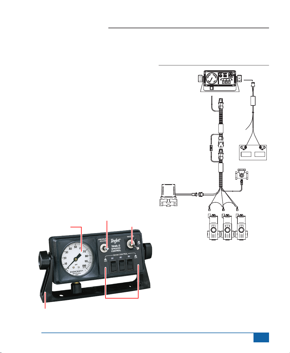
SYSTEM CONFIGURATIONS
Figure 1-1: Solenoid Valves
744A Console
Mounting Bracket
64-50023
Cable, Extension:
Valve,
Pressure
Regulating
35-50029
8’ 45-20091
15’ 45-20079
Cable, End:
8’ 45-20090
15’ 45-20089
18’ 45-20088
DC:
45-200 91
21720 -8
XX/X X
45-200 90
DC: XX /XX
TeeJet
45-20100
45-2010 0
xx/xx
21478 - 2
Cable,
Power
45-20100
Fitting, Tee
67-20004
Battery
Pressure Gauge
Mounting Bracket
Pressure Adjust Switch
Boom Control Switches
Master Switch
www.teejet.com
Solenoid Valves
1
Page 5
744A Sprayer Control
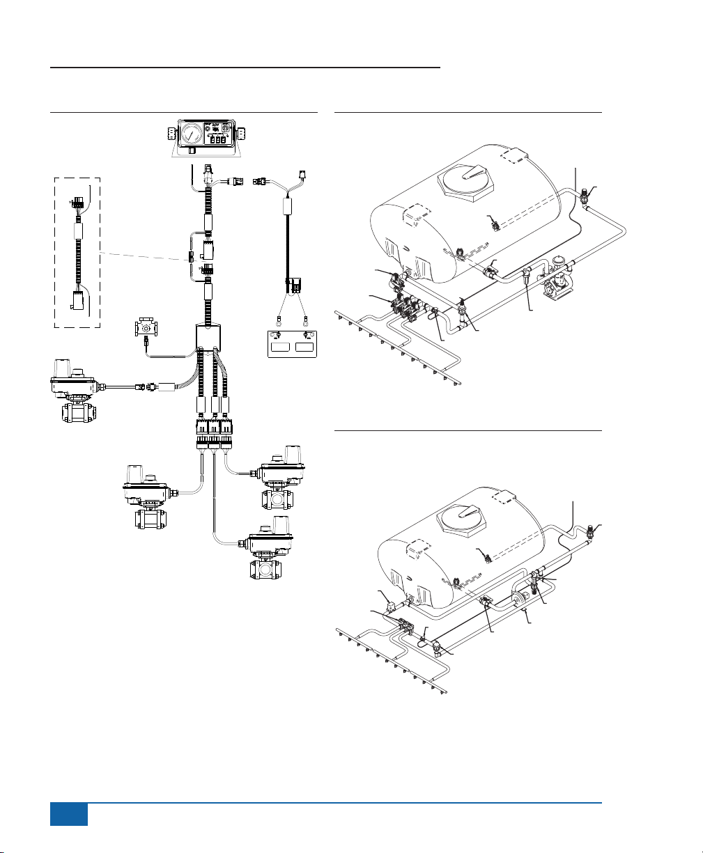
Figure 1-2: Ball Valves
744A Console
Cable, Extension
10’ 45-10086
Harness, 744
Console 12’
TeeJet
45-10086
DC: xx/xx
Harness, 744 Ball
Valve 45-10080
Valve, Regulating
35-02115
45-10072
Reg. Valve
DC: XX/XX
45-10072
TeeJet
TeeJet
45-10080
DC: xx/xx
Boom 3
Boom 2
Cable, Power
Fused
45-05385
Boom 1
45-05385
DC: xx/xx
Battery
Figure 1-3: Plumbing Diagram - Diaphragm Pump
To 744A
Controller
Jet Agitatior
Pressure Relief
Valve
Tank Shut Off
Diaphragm Pump
Line Strainer
Regulating Valve
Boom Valves 1-3
Boom 1
Gauge Tee
Boom 2
Boom 3
Figure 1-4: Plumbing Diagram - Centrifugal Pump
and Self-Cleaning Strainer
To 744A
Controller
Throttling Valve
2
www.teejet.com
Ball Valves
Boom 1
Directo Valve
Elecrical
Regulating
Valve
Boom 2
Boom3
Gauge Tee
Jet Agitator
Throttling
Valve
Shut-Off
Throttling Valve
Line Strainer
Throttling Valve
Centrifugal
Pump
Tank
Page 6

744A Sprayer Control
KIT CONTENTS
Unpack the installation kit and identify the required parts.
Item Part Number Description Quantity
1 67-20004 Tee Fitting, Nylon (Black) ......................................................................................... 1
2 67-20003 Male Connector, Nylon ............................................................................................1
3 67-20002 Tubing Nut, Nylon ....................................................................................................3
4 67-20005 Close Nipple, Nylon (Black) .....................................................................................1
5 65-50005 Tubing Insert, Brass ................................................................................................. 4
6 64-50023 Mounting Bracket, Nylon .......................................................................................... 1
7 60-10026 Lock Knob ................................................................................................................2
8 60-50000 1/4” External Tooth Lock Washer ............................................................................2
9 60-50003 1” Bolt, Steel, Zinc Plated ........................................................................................2
10 60-50001 Flat Washer, Steel, Zinc Plated ................................................................................ 2
11 60-50009 Lock Washer, Steel, Zinc Plated ..............................................................................2
12 350-0062 Hex Nut, Steel, Zinc Plated ...................................................................................... 2
13 67-20001 Male Coupling, Nylon ............................................................................................... 1
14 90-50141 Accessory Bag - Items 2, 3 ,5, & 7-13 .....................................................................1
15 75-50033 Control Housing 100 psi Liquid ................................................................................1
16 75-50035 Control Housing 300 psi Liquid ................................................................................1
17 98-70025 744A Manual ............................................................................................................ 1
Figure 1-5: Item Illustrations
Item Part # Description Illustration
1 67-20004 Tee Fitting, Nylon (Black)
2 67-20003 Male Connector, Nylon
www.teejet.com
3
Page 7

744A Sprayer Control
Item Part # Description Illustration
3 67-20002 Tubing Nut, Nylon
4 67-20005 Close Nipple, Nylon (Black)
5 65-50005 Tubing Insert, Brass
6 64-50023 Mounting Bracket, Nylon
7 60-10026 Lock Knob
8 60-50000 1/4” External Tooth Lock
Washer
9 60-50003 1” Bolt, Steel, Zinc Plated
10 60-50001 Flat Washer, Steel, Zinc
Plated
11 60-50009 Lock Washer, Steel, Zinc
Plated
4
www.teejet.com
Page 8

744A Sprayer Control
Item Part # Description Illustration
12 350-0062 Hex Nut, Steel, Zinc Plated
13 67-20001 Male Coupling, Nylon
14 90-50141 Accessory Bag - Items 2, 3,
5, & 7-13
15 75-50033 Control Housing 100 psi
Liquid
16 75-50035 Control Housing 300 psi
Liquid
17 98-70025 744A Manual
CONTROL HOUSING ASSEMBLY
New consoles have boom switches, guage lamps/LEDs and boom LED soldered to the circuit board.
Item Part Number Description
1 60-50020 Knurled Nut, Brass Nickel Plated
2 84-20002 Graphic Panel
3 64-50024 Front Housing
4 64-50031 Lens Gauge
5 51-20008 100 psi Liquid Gauge
5 51-20002 300 psi Liquid Gauge
6 60-50019 Square Nut (2 Req’d)
7 01-50007 Circuit Board
www.teejet.com
5
Page 9

744A Sprayer Control
Item Part Number Description (continued)
8 32-50010 Toggle Switch
9 350-2610 Plastic Screw
10 64-50030 Foam Spacer
11 64-50025 Back Housing
12 64-50029 Elbow, Nylon (Black)
13 64-50032 Output Cable Shield, Neoprene
14 64-50026 Receptacle Fuse Shield, Neoprene
15 604-0014 Fuse, 15A
Figure 1-6: Assembly
9
6
www.teejet.com
5
6
4
3
1
8
2
10
8
8
6
7
12
13
14
15
11
Page 10

744A Sprayer Control
CHAPTER 2 - INSTALLATION
MOUNTING BRACKET
1. Make sure all switches on the 744A Sprayer
Control are turned to the “Off” position.
2. Determine the best location for the 744A Sprayer
Control in the vehicle cab according to the
following guidelines:
• pressure gauge should be readily visible
• switches should be within easy reach
• controller bracket should rest on a at surface
• 12 volt DC power source must be accessible
(maximum draw 10 amps)
3. Determine the proper routing for power cables
and pressure tube:
• away from operators’ movement area
• away from moving parts
• away from sharp objects
4. Install the mounting bracket using ¼” (6.4mm)
drill, machine screws, nut, washers, and lock
washers as illustrated below. Attach the control
housing assembly to the mounting bracket using
the console adjusting knobs and washers.
Figure 2-1: Mounting Bracket
OUTPUT CONTROL CABLE
Cut a 1.0” (3.0 cm) diameter opening used to feed
the output control cable from the interior of the
tractor cab to the boom control valves. Make sure
the hole has no burrs or sharp edges that could
damage the wires.
744A-3 Unit
6 wires from the output cable are used to control a
three-section boom.
• Orange (Right) Yellow (Center) Green (Left) –
connect to 144A Valves. When using a
*344AEC Ball Valve, connect to the white wire.
• **Black – connect to other terminal on 144A
Valves. When using the *344AEC Ball Valve,
black is not connected.
• Red and Brown – connect to red and black
wires on the Regulator Valve (244, 344AE-PR,
or 344AE-RL).
*When using 344AEC DirectoValve® Ball Valves, connect black
wire(s) and red wire(s) using the Valve End and Battery End
Cables (supplied only when Ball Valve Kits are purchased) to an
uninterrupted power supply such as the battery.
**The black ground wire for the control cable is not supplied
with connectors attached. The T-Tap connectors are supplied
separately and should be attached as per Figure 2-2.
WARNING!: Do not plug the control cable into the
control box until it has been fully connected
to the control valves. Doing so may allow the
unconnected leads to short out.
www.teejet.com
7
Page 11

744A Sprayer Control
Figure 2-2: Figure 2-2: T-Tap Connector Assembly
Step A
Step B
To Terminal of
144 Directo Valve
Step C
Ball
Valve
Connector
Input Power Cable
The Input Power Cable consists of three wires. The
red wire should be connected to a 12 Volt power
supply within the cab of the vehicle (i.e., ignition
switch). If the power source is located outside of the
cab, the power cable should exit the cab through
the same 1.0” (3.0 cm) diameter hole as the output
control cable. The blue wire should be connected
to the headlight system of the tractor. This can
be accomplished by connecting the blue wire to
the auxiliary terminal of the headlight switch or by
splicing into the wire connected to the headlight.
The black wire is the negative lead and should be
connected to a good chassis ground.
Plug the input power cable into the power cable
socket on the back of the 744A console. Turn the
vehicle ignition switch to the “Run” position. If the
wiring has been connected properly, the boom
section indicator lights should illuminate when the
boom section switches are toggled. The gauge light
should appear when the headlights are illuminated.
Pressure Gauge
The tubing for the pressure gauge is supplied
as part of the wiring harness. To avoid chemical
leakage into the vehicle cab, the tube coupler
should be installed outside of the vehicle cab. If a
gauge isolator is used with the system, it should be
installed in place of the coupler, also outside of the
vehicle cab.
The pressure gauge should be checked for
accuracy each season. If the unit is equipped with
a liquid-lled gauge and it does not read accurately,
the gauge may need to be vented. To vent the
gauge, remove the four screws in the back of the
sprayer control housing and lift off the back. The
rear of the gauge will be exposed. To vent the
gauge, clip off the nib of the rubber plug in the back
of the gauge or puncture it with a needle. Once the
gauge has been vented, do not store the sprayer
control on its back as this may cause a loss of
uid from within the gauge. If further inaccuracy
is suspected at 0 PSI and a gauge isolator is
being used, the isolator line may need to be bled
according to the instructions furnished with the
gauge isolator.
8
www.teejet.com
Page 12

744A Sprayer Control
Pressure Gauge Tube Assembly
1. Determine the location at which the coupler is to
be installed. Cut the tubing at that point.
2. Remove the tube nuts from the 3 couplers
and slide the tubing through the nuts. The
threaded portion of the nut should face their
respective couplings. The tube should protrude
approximately ½” beyond the nut.
3. One brass tube insert is provided. This must be
used with the gauge coupling assembly.
4. A ¾” x ¾” nylon close nipple is provided if a
male connected is needed with the gauge tee
tting.
5. Fluid leakage around the gauge indicates a poor
connection or a defective gauge.
NOTE: All cables and tubes should be out of the
way of the operator’s feet and path so that
they cannot be snagged or pulled. These
tubes should be routed around sharp metal
objects, edges, and moving parts with
enough slack that they will not be pulled
apart when sharp turns are made.
Figure 2-3: Pressure Gauge Tube Assembly
744A Sprayer Control
Gauge Elbow
Tube Insert
Tube Nut
Solenoid Harness
2172 0-8
DC: XX /XX
45-20 091
Optional Isolator Kit
Tube Insert
Tube Coupling
Tube Insert
Solenoid Harness
Tube Nut
Tube Insert
45-20 09 0
DC:XX/XX
Solenoid Shutoff Valve
Tube Nut
Tube Nut
Pipe Nipple
www.teejet.com
9
Page 13

744A Sprayer Control
CHAPTER 3 - MAINTENANCE
Routine Procedures
Several routine procedures should be followed to
help maintain the 744A Sprayer Control system.
1. Check all wires and connections for wear,
damage, and frayed ends to prevent shorting out
of the system.
2. Make sure that the mounting bracket for the
744A Sprayer Control is mounted securely.
3. All connections and terminals should be free of
corrosion.
4. The control unit is designed so that it may be
removed, cleaned, and stored during periods of
non-use to protect it from extreme heat or cold.
5. The 744A Sprayer Control is NOT
WATERPROOF. Do not immerse the unit when
cleaning.
6. Periodic ushing of the sprayer will help prevent
clogging due to residue buildup.
Removal of Control Unit
1. De-pressurize the system.
2. Uncouple the nylon pressure tube from outside
the vehicle cab and allow the liquid to drain.
Uncouple the tube from the bottom of the unit.
3. Disconnect the input power cable from the back
of the unit.
4. Disconnect the output control cable from the
back of the unit.
5. Loosen the triangular knobs on both sides of the
unit and slide the unit off of the bracket.
10
www.teejet.com
Page 14

744A Sprayer Control
U S E R M A N U A L
TeeJet 744A manual Sprayer Control
for use with Solenoid or Ball Valves
• Manual spray controller in a compact package.
• Liquid lled 100 PSI or 300 PSI pressure gauge.
• Lighted pressure gauge for night use.
• Heavy-duty switches with LED indicators.
• Available in a variety of kit forms using solenoid or ball type control valves.
• DirectoValve shutoff ball valves are ordered separately for 744A ball valve kits.
• Kits include wiring harness.
1801 Business Park Drive
Springeld, Illinois 62703 USA
Tel: (217) 753-8424 • Fax: (217) 753-8426
www.teejet.com
98-70025 R1
© TeeJet Technologies 2010
 Loading...