

Page 1

F I E L D P I L O T®
U S E R M A N U A L
Assisted Steering Hydraulic Installation Manual for
Vehicle Kit Number 91-02292
Fits Only John Deere 6500 and 6700 Hi-Cycle
Page 2

Page 3

FieldPilot
®
FIELDPILOT®
Copyrights
© 2010 TeeJet Technologies. All rights reserved. No part of this document or the computer programs
described in it may be reproduced, copied, photocopied, translated, or reduced in any form or by any
means, electronic or machine readable, recording or otherwise, without prior written consent from TeeJet
Technologies.
Trademarks
Unless otherwise noted, all other brand or product names are trademarks or registered trademarks of their
respective companies or organizations.
Limitation of Liability
TEEJET TECHNOLOGIES PROVIDES THIS MATERIAL “AS IS” WITHOUT WARRANTY OF ANY KIND,
EITHER EXPRESSED OR IMPLIED. NO COPYRIGHT LIABILITY OR PATENT IS ASSUMED. IN NO
EVENT SHALL TEEJET TECHNOLOGIES BE LIABLE FOR ANY LOSS OF BUSINESS, LOSS OF PROFIT,
LOSS OF USE OR DATA, INTERRUPTION OF BUSINESS, OR FOR INDIRECT, SPECIAL, INCIDENTAL,
OR CONSEQUENTIAL DAMAGES OF ANY KIND, EVEN IF TEEJET TECHNOLOGIES HAS BEEN
ADVISED OF SUCH DAMAGES ARISING FROM TEEJET TECHNOLOGIES SOFTWARE.
www.teejet.com
1
Page 4
FieldPilot
®
PREPARATION
1. Before beginning the installation, thoroughly clean the vehicle to remove dirt and contaminants that might
get into the hydraulic circuit.
2. Park the vehicle on a clean, level oor with adequate clearance to work around.
3. Do not attempt to loosen any hydraulic ttings while the engine is running.
4. Allow the motor and the hydraulics to cool until it is no more than warm to the touch before proceeding.
5. Prior to loosening any hydraulic ttings, be sure to have the appropriate plugs and caps available in order
to limit loss of hydraulic uid from the open ttings.
PREVENT HYDRAULIC SYSTEM CONTAMINATION. It is essential to thoroughly clean hydraulic
system ttings and hose connections prior to disconnecting or removing them. Use a spray
cleaner such as “Brake Clean” to prevent hydraulic system contamination. Note that o-rings used
on ORB and ORFF type ttings may be damaged by solvent cleaners such as “Brake Clean”. If a tting is to
be cleaned internally, the o-ring should rst be removed and cleaned with a berless cloth.
TO AVOID EXCESS LEAKAGE, DO NOT TURN THE STEERING WHEEL WHILE THE
FITTINGS ON THE MANUAL STEERING VALVE ARE DISCONNECTED.
WARNING: HOT, HIGH PRESSURE FLUID HAZARD. Hydraulic oil may be hot and under
extreme pressure. To prevent serious injury or death, relieve system pressure and allow the
system to cool before repairing or disconnecting. Wear proper hand and eye protection when
searching for leaks, using wood or cardboard instead of hands. Keep all hydraulic components in good repair.
WARNING: PINCH POINT HAZARD! To prevent serious injury or death, avoid unsafe practice
while manually operating hydraulic steering circuits. Keep others away and stay clear of
mechanical steering linkages.
2
www.teejet.com
Page 5

FieldPilot
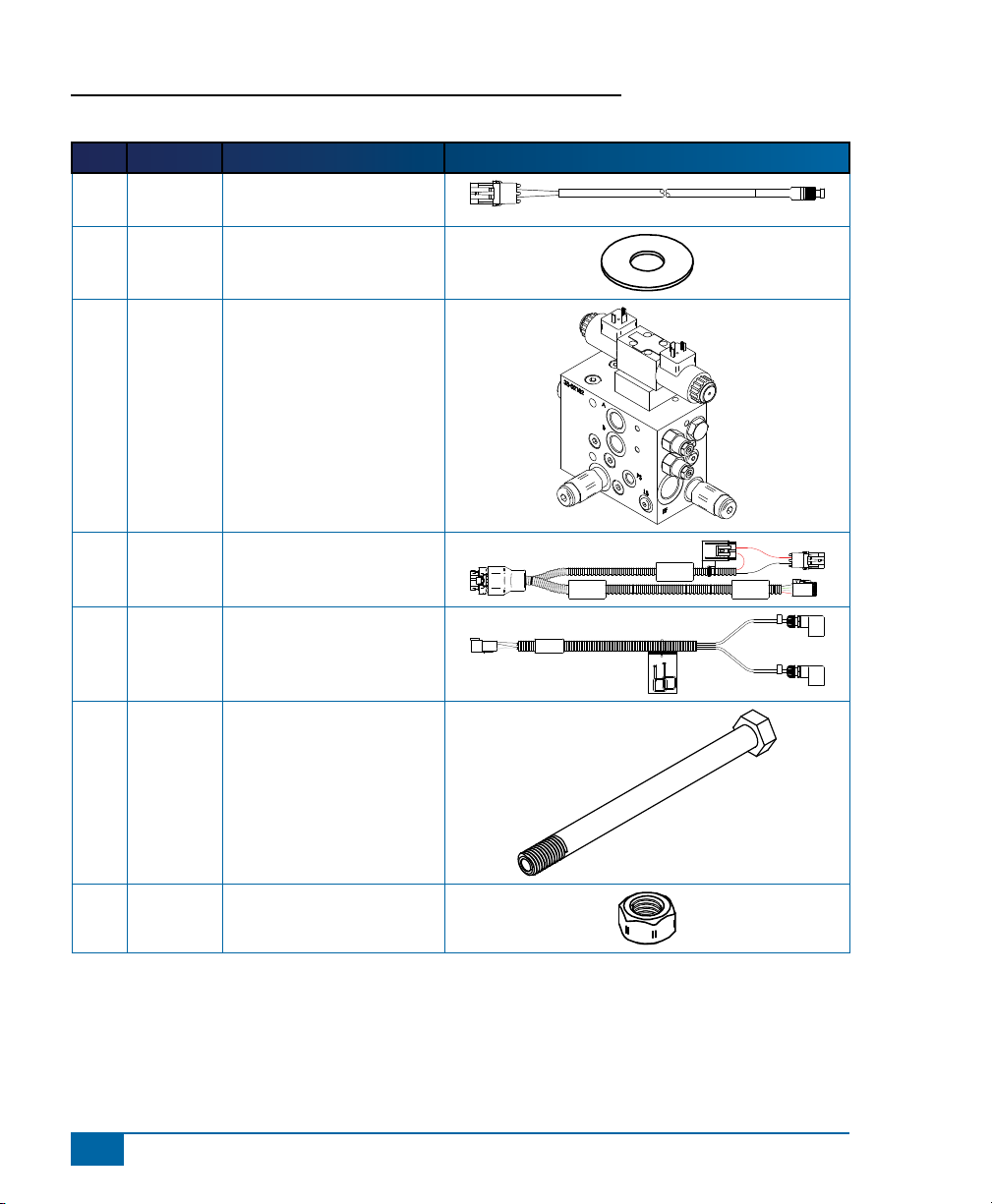
KIT CONTENTS
Unpack the installation kit and identify the required parts.
Item Part Number Description Quantity
A 32-04040 Switch, Engage/Disengage ......................................................................................1
B 350-0037 Washer, Narrow Flat - 3/8”, SST ..............................................................................2
C 35-02183 Valve, FieldPilot PWM, 1.1GPM, OC .......................................................................1
D 45-07703 Harness, SCM .........................................................................................................1
E 45-10103 Harness, Valve .........................................................................................................1
F 60-04089 Bolt, Hex, 3/8-16 x 3-3/4” SST .................................................................................2
G 60-07027 Nut, NyLock 3/8-16, SST .........................................................................................2
H 65-05155 Bracket, FieldPilot Valve Mount ...............................................................................1
I 68-01236 Hose, Hyd - 1/2” x 70”, #8MORF X #8FJIC 90º .......................................................1
J 68-01237 Hose, Hyd - 1/2” x 78”, #8FORF X #8FJIC .............................................................1
K 68-01238 Hose, Hyd - 1/2” x 45”, #8FORF X #8FJIC .............................................................1
L 68-01239 Hose, Hyd - 3/8” x 83”, #6FORF X #6FJIC 90º ........................................................1
M 68-01240 Hose, Hyd - 3/8” x 192”, #6FJIC X #6FORF 90º ...................................................... 2
N 68-02071 Adapter, Hyd. Run Tee - #6 ORF .............................................................................3
O 68-02075 Adapter, Hyd. 90º - #6MORF x #8MORB ................................................................ 1
P 68-02078 Adapter, Hyd. 90º - #6MJIC x #6FJIC .....................................................................2
Q 68-02082 Adapter, Hyd. - #6MJIC x #8MORB ........................................................................3
R 68-02093 Adapter, Hyd. 90º - #8MJIC x #8FJIC .....................................................................1
S 68-02122 Adapter, Hyd. - #8MJIC x #12MORB .......................................................................2
T 90-50013 Cable Tie Kit, 15 ......................................................................................................2
U 91-07011 Steering Wheel Switch Kit .......................................................................................1
V 98-05214 Installation Manual, FP JD 6500, 6700 Hi-Cycle .....................................................1
®
www.teejet.com
3
Page 6
FieldPilot
®
Item Part # Description Illustration
A 32-04040 Switch, Engage/Disengage,
Momentary
B 350-0037 Washer, Narrow Flat - 3/8",
SST
C 35-02183 Valve, FieldPilot PWM,
1.1GPM, OC
D 45-07703 Harness, SCM
E 45-10103 Harness, Valve
F 60-04089 Bolt, Hex, 3/8-16 x 3-3/4"
SST
G 60-07027 Nut, NyLock 3/8-16, SST
45-10103
DC:xx/xx
SCM Power I/O
45-07703
DC: xx/xx
Power
Valve Output
A
B
4
www.teejet.com
Page 7
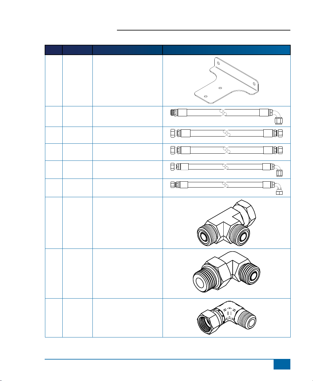
Item Part # Description Illustration
H 65-05155 Bracket, FieldPilot Valve
Mount
I 68-01236 Hose, Hyd - 1/2" x 70",
#8MORF X #8FJIC 90º
J 68-01237 Hose, Hyd - 1/2" x 78",
#8FORF X #8FJIC
K 68-01238 Hose, Hyd - 1/2" x 45",
#8FORF X #8FJIC
L 68-01239 Hose, Hyd - 3/8" x 83",
#6FORF X #6FJIC 90º
M 68-01240 Hose, Hyd - 3/8" x 192",
#6FJIC X #6FORF 90º
FieldPilot
®
N 68-02071 Adapter, Hyd. Run Tee - #6
ORF
O 68-02075 Adapter, Hyd. 90º - #6MORF
x #8MORB
P 68-02078 Adapter, Hyd. 90º - #6MJIC
x #6FJIC
www.teejet.com
5
Page 8
FieldPilot
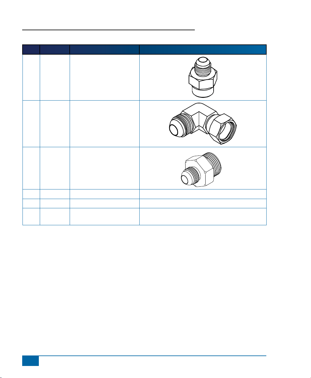
Item Part # Description Illustration
Q 68-02082 Adapter, Hyd. - #6MJIC x
R 68-02093 Adapter, Hyd. 90º - #8MJIC
S 68-02122 Adapter, Hyd. - #8MJIC x
T 90-50013 Cable Tie Kit, 15
U 91-07011 Steering Wheel Switch Kit
V 98-05214 Installation Manual, FP JD
®
#8MORB
x #8FJIC
#12MORB
6500, 6700 Hi-Cycle
6
www.teejet.com
Page 9

Figure 1-1: Hydraulic Diagram
FieldPilot
®
Hose M
Hose M
L T
Manual
Steering
Valve
R P
Hose J or K
EF
FieldPilot
Valve
A
B
Pressure into Orbital
Hose I
P
Hose L
T
Tank
Auxiliary
Pump
P
John
Deere
Manifold
T T
Existing Hoses
Hoses From Kit
Out to
Boom Functions
www.teejet.com
7
Page 10

FieldPilot
®
INSTALLATION
If there are questions concerning the installation of the FieldPilot system on this vehicle, or due to
the changes in component specications the parts supplied in the kit are not exactly as presented
in this document, please contact your dealer or TeeJet Customer service representative for
clarication before installation. TeeJet Technologies is not responsible for misuse or incorrect installation of
the system.
NOTE: BE VERY CAREFUL TO ABSOLUTELY SECURE ALL CABLES AND HOSES SO THAT THEY
DON’T INTERFERE WITH THE MANY MOVING PARTS OF THE MACHINE!
NOTE: All references to left and right are stated as if the user is seated in the driver’s seat.
1. PrePare the FieldPilot ValVe
Install adapters (S) in the P and EF ports of the FieldPilot valve (C). Attach adapter (R) onto adapter (S) in
the P port. Install adapters (Q) in the A, B, and T ports. Then attach adapter (P) onto adapters (Q) in the A
& B ports.
Figure 1-2: Prepare the FieldPilot Valve
R
S
Q
8
www.teejet.com
Q
Q
P
S
Page 11
FieldPilot
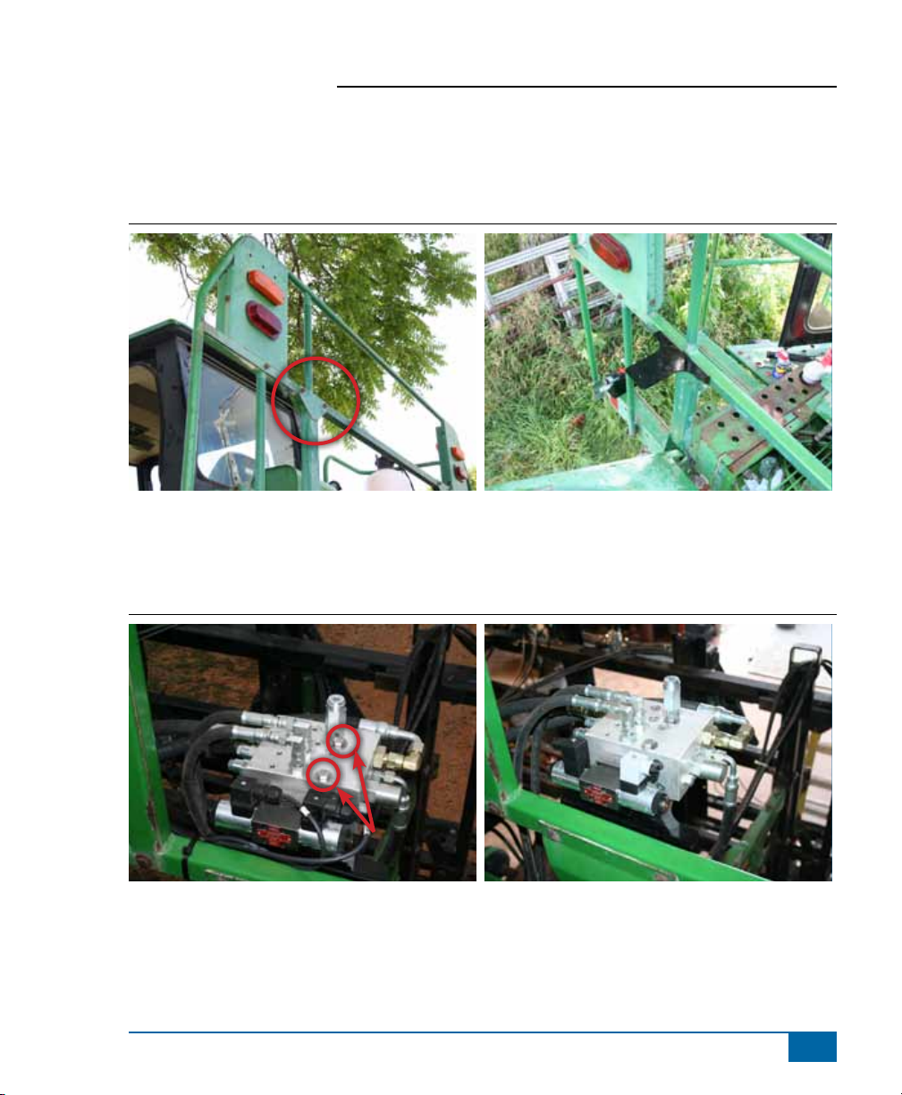
2. install the FieldPilot ValVe Bracket
The valve bracket will mount on the left side on the rear of the vehicle on the railing. Remove the two bolts
as shown and install bracket (H) using the original bolts.
Figure 1-3: Install Mounting Bracket for FieldPilot Valve
3. Mount the FieldPilot ValVe
Mount the FieldPilot Valve to the bracket using parts (B, F, & G). Mount it so that the P and T ports are
facing left and the EF port is facing right.
®
Figure 1-4: Mount the FieldPilot Valve
B, F, G
www.teejet.com
9
Page 12

FieldPilot
®
4. install tank hose and adaPter
John Deere 6500
Locate the hydraulic manifold as shown. It is located behind the cab, under the catwalk. Remove the
plug labeled R4 and install adapter (O). Then connect hose (L) from this adapter (O) to the T port of the
FieldPilot valve.
Figure 1-5: Install Tank Hose and Adapter
O
10
www.teejet.com
L
L
Page 13

FieldPilot
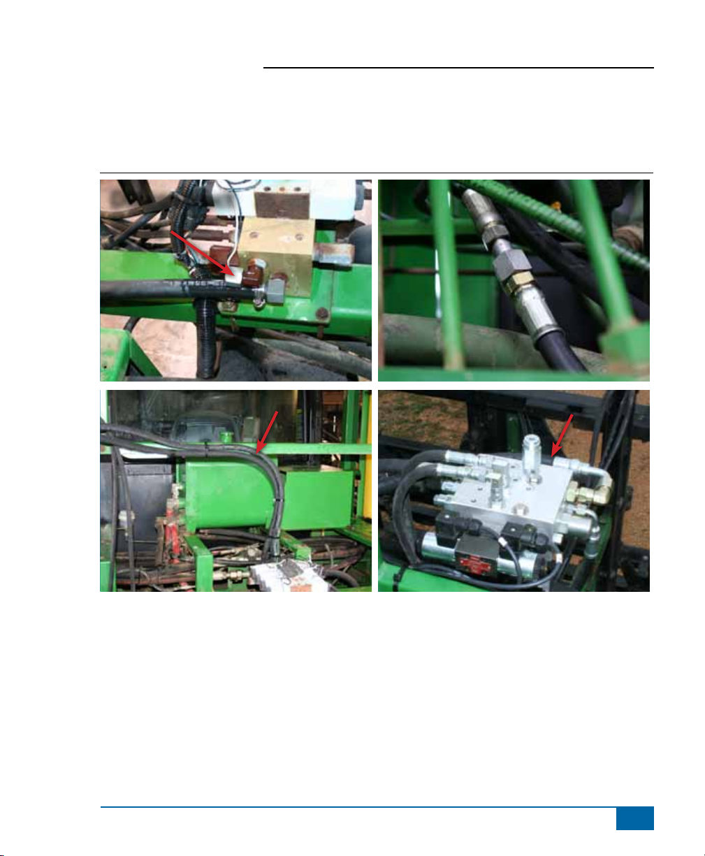
John Deere 6700
Locate the tank hose as shown. It is located behind the cab, under the catwalk. Disconnect the indicated
hose and install run tee (N). Reconnect original hose to run of the tee. Then connect hose (L) from the
branch of the run tee to the T port of the FieldPilot valve.
Figure 1-6: Install Tank Hose and Adapter
®
Disconnect Hose
N
L
L
www.teejet.com
11
Page 14

FieldPilot
®
5. install Pressure hose and adaPter
John Deere 6500
Locate the hydraulic manifold as shown. Disconnect the hose indicated then connect hose (I) to the original
pressure hose and route it to the P port of the FieldPilot valve.
Figure 1-7: Install Pressure Hose and Adapter
Disconnect Hose
I
12
www.teejet.com
I
I
Page 15
FieldPilot
John Deere 6700
Locate the hydraulic manifold as shown. Disconnect the hose to P port as indicated then connect hose (I) to
the original pressure hose and route it to the P port of the FieldPilot valve.
Figure 1-8: Install Pressure Hose and Adapter
®
Disconnect
Hose
I
www.teejet.com
I
13
Page 16

FieldPilot
®
6. install eF hose
John Deere 6500
From the open tting from the previous step connect hose (J) and route it to the EF port of the FieldPilot
valve.
Figure 1-9: Install EF Hose
Connect Hose J
J
14
www.teejet.com
J
Page 17

FieldPilot
John Deere 6700
From the open tting from the previous step connect hose (K) and route it to the EF port of the FieldPilot
valve.
Figure 1-10: Install EF Hose
K
Connect Hose K
®
K
K
www.teejet.com
15
Page 18

FieldPilot
®
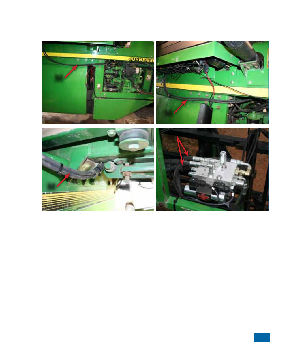
7. install steering hoses and adaPters
Locate the steering hoses from the orbital that connect to steel directly above the engine. Label both
hoses and disconnect them. Then install run tees (N) on both lines with the branch of the tees facing up.
Reconnect the original steering hoses to the run of the tees (N). Next connect the steering hoses (M) to the
branch of the tees and route them to the A & B ports of the FieldPilot valve. The hoses will exit the engine
compartment on the right side and route along the right side of the machine. Just in front of the rear axle the
hoses will cross over to the left side and the route back and up to the FieldPilot valve.
Figure 1-11: Install Steering Hoses and Adapters
Steering Hoses
16
www.teejet.com
N
M
M
N
Page 19
M
FieldPilot
®
M
M
M
www.teejet.com
17
Page 20

FieldPilot
®
8. install steering disengage switch (kit 91-07011)
The steering disengage kit (U) is used to automatically disengage FieldPilot when the steering wheel is
turned. The magnets mount on the steering shaft or other rotating part of the steering wheel and the sensor
mounts so that there is a 1/8” clearance between the sensor and magnet.
Figure 1-12: Install Steering Disengage Switch (Kit 91-07011)
9. installation oF engage/disengage switch
Connect item (A) to the connector on the SCM harness labeled Remote Engage/Disengage. Install the push
button in a location that is easily accessible during operation of the machine. This switch (A) is not required
if the optional foot switch 32-04020 is used.
Figure 1-13: Engage/Disengage Switch
18
www.teejet.com
Page 21

FieldPilot
10. install ValVe control caBle
The valve control cable (E) will connect to the solenoids on the FieldPilot valve. Route it into the cab. Use
zip ties to secure it so that it doesn’t interfere with any moving parts.
Figure 1-14: Install Valve Control Cable
E
®
www.teejet.com
19
Page 22
FieldPilot
®
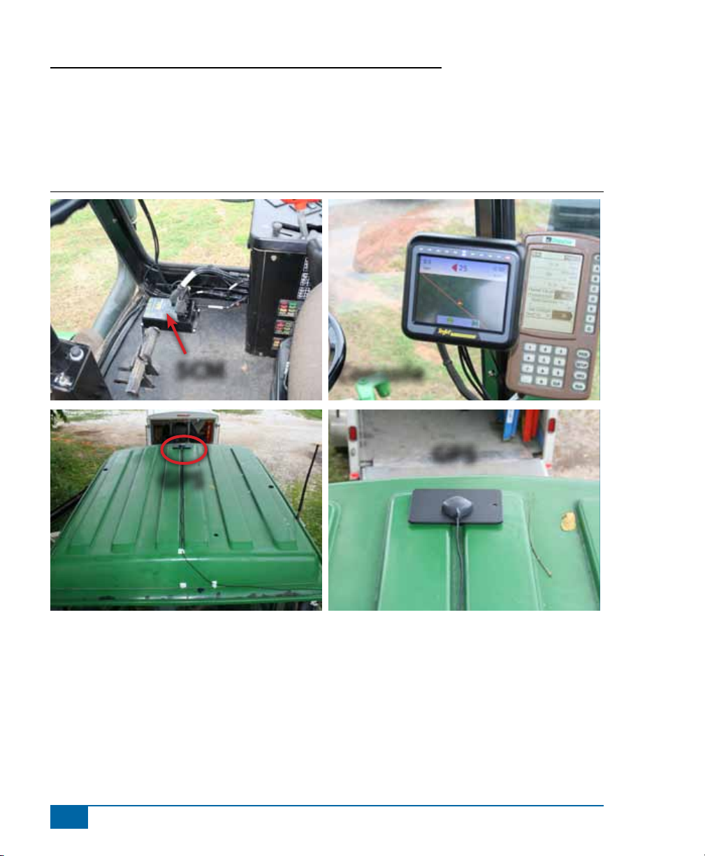
11. recoMMended electronics installation
The Steering Control Module (SCM) should be mounted securely to the oor of the cab as far forward in the
cab as possible. The control console can be mounted to the operator’s preference. The GPS antenna should
be mounted near the nose of the vehicle on a metal surface of at least 4” square.
Figure 1-15: Recommended Electronics Installation
SCM
GPS
Console
GPS
20
www.teejet.com
Page 23

FieldPilot
®
12. VeriFY oPeration oF hYdraulics
and set the steering control rate
Clean and pick up the area around the vehicle and make certain that it is safe to operate. Start the engine
and check hydraulic connections for leaks. Rotate the steering wheel from one extreme to the other and back
to center, check for leaks. While steering through the extremes of movement, check the cables and hoses for
wear points and strain, adjust as necessary.
The nal oil ow rate adjustment is accomplished through the Matrix console.
The target lock to lock time is 6 seconds. The valve frequency is 110. Refer to the
Matrix manual for further instructions.
NOTE: To activate the manual overrides, a tool such as a small screwdriver or allen wrench must be inserted
into the end of the coil to depress the override button.
WARNING: PINCH POINT HAZARD! To prevent serious injury or death, avoid unsafe practice
while manually operating hydraulic steering circuits. Keep others away and stay clear of
mechanical steering linkages.
13. coMPlete electronic installation
Refer to the owner’s manual supplied with the automated steering system to complete the electronic
installation and setup.
www.teejet.com
21
Page 24

F I E L D P I L O T®
U S E R M A N U A L
A series of equipment-specic hydraulic installation kits have been
developed to work in conjunction with your assisted steering system. This
kit contains the necessary components and instructions to install assisted
steering hydraulics on the John Deere 6500 and 6700 Hi-Cycle. Please
review this manual thoroughly before beginning the installation process.
1801 Business Park Drive
Springeld, Illinois 62703 USA
Tel: (217) 753-8424 • Fax: (217) 753-8426
www.teejet.com
98-05214 R0
© TeeJet Technologies 2010
 Loading...