

Page 1

SENTRY 6140
USER MANUAL
Tip Flow Monitor
Page 2

Copyrights
© 2013 TeeJet Technologies. All rights reserved. No part of this document or the computer programs described in it may be reproduced, copied,
photocopied, translated, or reduced in any form or by any means, electronic or machine readable, recording or otherwise, without prior written
consent from TeeJet Technologies.
Trademarks
Unless otherwise noted, all other brand or product names are trademarks or registered trademarks of their respective companies or organizations.
Limitation of Liability
TEEJET TECHNOLOGIES PROVIDES THIS MATERIAL “AS IS” WITHOUT WARRANTY OF ANY KIND, EITHER EXPRESSED OR IMPLIED.
NO COPYRIGHT LIABILITY OR PATENT IS ASSUMED. IN NO EVENT SHALL TEEJET TECHNOLOGIES BE LIABLE FOR ANY LOSS OF
BUSINESS, LOSS OF PROFIT, LOSS OF USE OR DATA, INTERRUPTION OF BUSINESS, OR FOR INDIRECT, SPECIAL, INCIDENTAL, OR
CONSEQUENTIAL DAMAGES OF ANY KIND, EVEN IF TEEJET TECHNOLOGIES HAS BEEN ADVISED OF SUCH DAMAGES ARISING FROM
TEEJET TECHNOLOGIES SOFTWARE.
Safety Information
TeeJet Technologies is not responsible for damage or physical harm caused by failure to adhere to the following safety requirements.
As the operator of the vehicle, you are responsible for its safe operation.
The Sentry 6140 is not designed to replace the vehicle’s operator.
The Sentry 6140 is designed to support and improve efciency while working in the eld. The driver has full responsibility for the quality and work
related results.
Photos and illustrations may vary form the actual components provided. This may be due to different installation options, operation modes or
production models.
Always try to use original parts. Built to the highest standards of safety and reliability, TeeJet Technologies parts are to be used for this system as
others might jeopardize the safety and function of the system. TeeJet is not responsible for any redesign or adaptations of the Sentry 6140. Any
changes to the Sentry 6140 voids the company warranty.
Page 3

Sentry 6140 Tip Flow Monitor
Table of Contents
COMPONENTS 2
Boom Series Harness Connection .................................................................................................................................................................. 5
SYSTEM COMPONENTS 6
Sentry 6140 Console ............................................................................................................................................................................................ 6
Nozzle Body with Flow Meter and Tip Sensor Interface ......................................................................................................................... 6
Flow Meter Assembly .....................................................................................................................................................................7
Kit Assembly ..................................................................................................................................................................................7
POWER 8
SETUP 9
Display Brightness ..............................................................................................................................................................................................10
Master Sound ....................................................................................................................................................................................................... 10
Tip Alarm Percentage ........................................................................................................................................................................................10
Tip Alarm Delay ...................................................................................................................................................................................................10
Number of Sections ........................................................................................................................................................................................... 11
Number of Tips per Section ............................................................................................................................................................................11
Boom Section On/O Beep .............................................................................................................................................................................11
TIP BALANCE 12
OPERATION 13
On Screen Indicators ...................................................................................................................................................................13
System Errors ........................................................................................................................................................................................................13
98-05306-ENUS R2
1
Page 4
Sentry 6140 Tip Flow Monitor
COMPONENTS
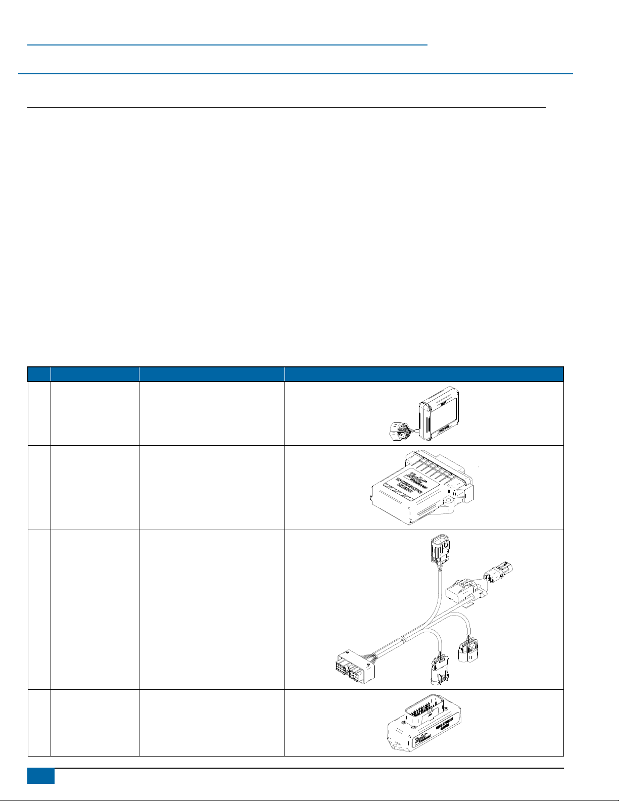
Unpack the installation kit and identify the required parts for your installation.
Item Part Number Description Quantity
A 75-30100 Sentry 6140 Console .......................................................................................................................................................1
B 78-05101 Tip Flow Monitor Interface (TFMI) ....................................................................................................................................1
C 45-10148 Tip Flow Monitor Interface (TFMI) Harness .....................................................................................................................1
D 78-05091 Boom Interface Module (BIM) ..........................................................................................................................................1
E 45-10142* Boom Interface Module (BIM) Harness ...........................................................................................................................1
F varies Harness to Tip Sensor Interface Extension Cable ...................................................................................................varies
45-05857: 3′/1 m, 45-05858: 6′/1.8 m, 45-05859: 12′/3.6 m, 45-05864: 35′/10.7 m
G varies Console to TFMI Harness Extension Cable .............................................................................................................varies
45-05900: 5′/1.5 m, 45-05901: 10′/3 m, 45-05902: 20′/6 m, 45-05903: 40′/12 m
H 78-05104 Tip Sensor Interface.................................................................................................................................................varies
I 78-05105 Dual Tip Sensor Interface ........................................................................................................................................ varies
J 57-00122 Nozzle Flow Meter ................................................................................................................................................... varies
K 45-05856 Terminator, End (Male) ....................................................................................................................................................1
L 45-05855 Terminator, Start (Female) ...............................................................................................................................................1
*Actual harness may be machine specific.
Item Part # Description Illustration
A 75-30100 Sentry 6140 Console
B 78-05101 Tip Flow Monitor Interface (TFMI)
C 45-10148
Tip Flow Monitor Interface (TFMI)
Harness
D 78-05091 Boom Interface Module (BIM)
2
www.teejet.com
Page 5
Sentry 6140 Tip Flow Monitor
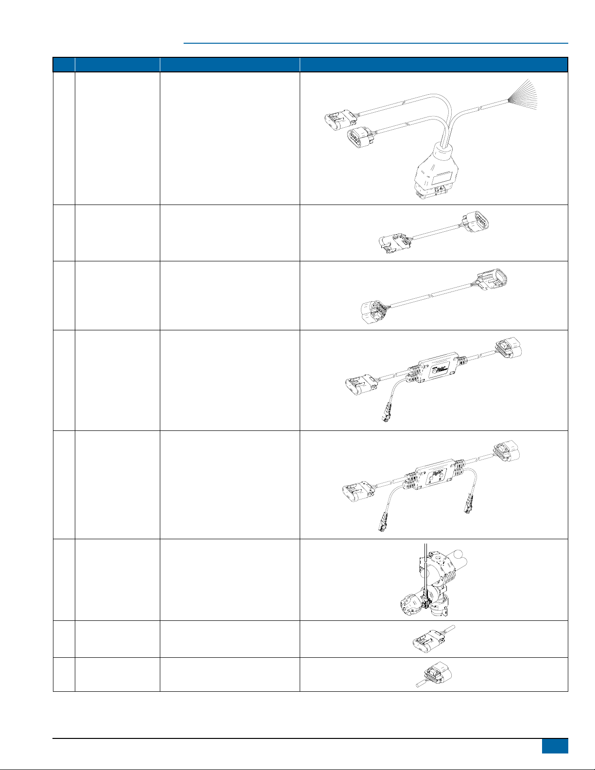
Item Part # Description Illustration
Boom Interface Module (BIM)
E 45-10142
45-05857: 3′/1 m,
45-05858: 6′/1.8 m,
F
45-05859: 12′/3.6 m,
45-05864: 35′/10.7 m
45-05900: 5′/1.5 m,
45-05901: 10′/3 m,
F
45-05902: 20′/6 m,
45-05903: 40′/12 m
Harness (Actual harness may be
machine specific.)
Harness to Tip Sensor Interface
Extension Cable
Console to TFMI Harness
Extension Cable
G 78-05104 Tip Sensor Interface
H 78-05105 Dual Tip Sensor Interface
I 57-00122 Nozzle Flow Meter
J 45-05856 Terminator, End (Male)
K 45-05855 Terminator, Start (Female)
98-05306-ENUS R2
3
Page 6

Sentry 6140 Tip Flow Monitor
Figure 1: System Diagram
75-30100
Sentry 6140
Console
45-05900: 5′/1.5 m
45-05901: 10′/3 m
45-05902: 20′/6 m
45-05903: 40′/12 m
Console to TFMI Harness Extension Cable
401-0016 Battery Adapter
45-10142
BIM Harness
45-05855
Terminator,
Start (Female)
78-05101
Tip Flow Monitor
Interface (TFMI)
45-05857: 3′/1 m
45-05858: 6′/1.8 m
45-05859: 12′/3.6 m
45-05864: 35′/10.7 m
Harness to Tip Sensor Interface Extension Cable
78-05105
Dual Tip Sensor Interface
45-10148
TFMI Harness
57-00122
Nozzle Flow Meter
Terminator, End (Male)
45-05856
75-05104
Tip Sensor
Interface
78-05091
Boom Interface
Module (BIM)
Section 1
The sections are numbered from left to right
while standing at the back of the machine
and begin at the Start Terminator.
4
www.teejet.com
Page 7

Sentry 6140 Tip Flow Monitor
Boom Series Harness Connection
With each machine having a different possible switchbox conguration, it is impossible to specify the exact location to T-Tap
into the valve harness. However, the following guidelines may provide some assistance in completing the installation.
1. Identify boom section cable that runs from the Boom Switchbox to the boom valves.
2. Use a T-Tap (or similar product) to connect into the signal wire.
NOTE: In some cases, the Boom Series Harness wires can be connected directly to the switches inside the Switchbox
using the proper spade terminal.
3. Repeat this process for each individual boom section.
Figure 2: Boom Series Harness Connection
RATE CONTROLLER
Detail A
45-10142
Boom Sense Harness
A
Ground
Wire
+Power
Wire
Boom Series Harness
Boom Wire
Wire Tap
Boom Valve
Signal Wire
98-05306-ENUS R2
5
Page 8

Sentry 6140 Tip Flow Monitor
SYSTEM COMPONENTS
If there are questions concerning the installation of the Sentry 6140 system on this vehicle, or due to the changes in component
specications the parts supplied in the kit are not exactly as presented in this document, please contact your dealer or TeeJet
Customer service representative for clarication before installation. TeeJet Technologies is not responsible for misuse or incorrect
installation of the system.
Sentry 6140 Console
The Sentry 6140 Console is designed to provide years of service under typical agricultural operating conditions. A tight tting enclosure means
that typical dusty environments will not cause operational problems. While occasional splashing of water will not damage the unit, the Sentry 6140
Console is not designed for direct exposure to rain. Take care not to operate the Sentry 6140 Console in wet conditions.
Figure 3: Sentry 6140 Console Front and Back
Power Switch
Bright Touch Screen
USB Port
to Tip Flow Monitor Interface
Harness Connection
Standard RAM Bracket
Nozzle Body with Flow Meter and Tip Sensor Interface
The turbine style ow meter used with the Sentry 6140 Tip Flow Monitor is compact, reliable and proven. The threaded connection allows the
sensor to be added onto a wide range of standard TeeJet single and multiple outlet nozzle bodies. ChemSaver® diaphragm check valves remain
in place allowing for positive spray tip shutoff. Ample clearance inside the ow meter means minimal ow restriction and generous free passage
for particles contained in the spray solution. Long wearing materials are used in bearing surfaces to ensure a consistent ow reading and the ow
meter sensor is mounted externally to prevent any direct contact with the spray solution for long-term reliability.
Figure 4: Flow Monitor Assembly
Nozzle Body & Tips
Tip Sensor Interface
to next Tip Sensor Interface
or Start Terminator
6
www.teejet.com
Tip Sensor
to next Tip Sensor Interface
or End Terminator
Nozzle Body End Cap
Tip Sensor Interface LED Flow Meter
Page 9

Sentry 6140 Tip Flow Monitor
Flow Meter Assembly
The ow meter gasket has two different sides. The side with the larger
center is to be inserted towards the sensor or inside the ow meter.
Figure 5: Flow Meter and Gasket
Flow Meter
Gasket
Figure 6: Gasket Detail
Towards
ow meter
Figure 7: Nozzle Body with Flow Meter Assembly
Nozzle Body
Flow Meter
Nozzle Body
End Cap
Figure 8: Sensor & Clips
Clips
Kit Assembly
1. Remove end cap from nozzle body.
2. Attach end cap to ow meter (J).
3. Attach ow meter to nozzle body. Hand tighten.
4. Loosely secure Tip Sensor Interface (H or I) close to nozzle body
/ ow meter assembly. Cable ties (not included) can be threaded
through Tip Sensor Interface slots.
5. Push sensor of Tip Sensor Interface into slot on owmeter. Clips on
ow meter should be in the groves on the center of the sensor.
6. Secure Tip Sensor Interface.
7. Connect Start Terminator (L) to section 1 Tip Sensor Interface.
8. Connect each Tip Sensor Interface moving from left to right (while
standing at the back of the machine).
►Extension cables from Boom Interface Module Harness (E) and
Tip Flow Monitor Interface Harness (C) will connect between
two Tip Sensor Interfaces.
9. Connect End Terminator (K) to the last section’s Tip Sensor
Interface.
Sensor
Figure 9: Tip Sensor Interface Slots
Tip Sensor Interface slots
98-05306-ENUS R2
7
Page 10

Sentry 6140 Tip Flow Monitor
Sentry 6140
Tip Flow Monitor
Test-v1.00h ©2012 TFMI V1.00g
POWER
Slide the POWER SWITCH to power on or off the console.
On power up the console detects the number of Tip Sensor
Interfaces (TSI) (H or I) on the boom and displays the status of the
sensors and the system. The LED’s on each TSI are turned on and go
off as each is detected and given their unique address.
The addresses start at #1 and continue across the boom. Tips
are numbered from left to right while standing in the forward facing
direction of the machine and begin at the Start Terminator.
►Sensor connected to the Start Terminator [female] (L) on the left
side of the machine will be #1
►Sensor connected to the End Terminator [male] (K) on the right
side of the machine will be the last sensor.
The Status Box displays if all tips are OK or if any errors are found.
Figure 10: Splash Screen
Figure 12: Home Screen
Boom Status
Status Box
Setup
NOTE: Screen options may vary depending on enabled or disabled
Tip Balance Next Error
functions as well as function availability.
Reset
Console Software
Version
Figure 11: Tip Sensor Interface LEDs
TFIM Software
Single Tip Sensor Interface
Dual Tip Sensor Interface
Version
The Balance button will be unavailable or grayed out
boom sections and the master switch are not on.
if all
8
www.teejet.com
Page 11

SETUP
If there are questions concerning the setup of the Sentry 6140,
please contact your dealer or TeeJet Customer service
representative for clarication before operation. TeeJet Technologies is
not responsible for misuse or incorrect operation of the system.
Setup is used to congure Display Brightness, Master Sound, Tip Alarm
Percentage, Tip Alarm Delay, Number of Sections, Number of Tips per
Section and Boom Section On/Off Beep.
Figure 13: Setup Button on Home Screen
Sentry 6140 Tip Flow Monitor
Figure 15: Setup Screen Order
◄ Display Brightness – Sets the
brightness level of the display
◄ Master Sound – Enable/disable
console sound
◄ Tip Alarm Percentage – Sets
the error reporting range for the
tip sensors
Figure 14: Buttons on Setup Screens
Home
Screen
Previous
Page
Next
Page
◄ Tip Alarm Delay – Sets the time
the console will wait after an
error has been encountered
before sounding a tip alarm
◄ Number of Sections – Sets the
number of boom sections
◄ Number of Tips per Section –
Enters the number of tips on
each boom section
◄ Boom Section On/Off Beep –
Enable/disable beep when a
boom section is turned on or off
98-05306-ENUS R2
9
Page 12

Sentry 6140 Tip Flow Monitor
Display Brightness
Sets the brightness level of the display. Range is 5% to 100% in
5% increments.
1. Press the MINUS/PLUS buttons
2. Press
►NEXT PAGE button
►PREVIOUS PAGE button
Off Beep.
Figure 16: Display Brightness
to proceed to Master Sound.
to adjust the brightness.
to go back to Boom Section On/
Master Sound
Enable/disable console sound.
1. Press the UP/DOWN buttons
2. Press
►NEXT PAGE button
►PREVIOUS PAGE button
Figure 17: Master Sound
to toggle the sound on or off.
to proceed to Tip Alarm Percentage.
to go back to Display Brightness.
Tip Alarm Percentage
Sets the error reporting range for the tip sensors. If the ow
rate of an individual tip falls below, or rises above this range,
the console will generate an alarm. The value entered is the
percentage above and below the average ow that a tip must pass
to trigger an alarm. Range is 0% to 100%.
1. Press the MINUS/PLUS buttons
2. Press
►NEXT PAGE button
►PREVIOUS PAGE button
Figure 18: Tip Alarm Percentage
to proceed to Tip Alarm Delay.
to adjust the percentage.
to go back to Master Sound.
Tip Alarm Delay
Sets the time the console will wait after an error has been
encountered before sounding a tip alarm. If the error is corrected
within this time, no alarm will sound or error will display on screen. The
delay value is selectable from 1 to 10 seconds.
1. Press the MINUS/PLUS buttons
2. Press
►NEXT PAGE button
►PREVIOUS PAGE button
Percentage.
Figure 19: Tip Alarm Delay
to proceed to Number of Sections.
to adjust the time.
to go back to Tip Alarm
10
www.teejet.com
Page 13

Sentry 6140 Tip Flow Monitor
Number of Sections
Select the number of boom sections. The sections are numbered
from left to right while standing in the forward facing direction of
the machine and begin at the Start Terminator. Range is 1 to 15
sections.
1. Press the MINUS/PLUS buttons
boom sections.
2. Press
►NEXT PAGE button
Section.
►PREVIOUS PAGE button
Figure 20: Number of Sections
to proceed to Number of Tips per
to adjust the number of
to go back to Tip Alarm Delay.
Figure 21: Tips per Section
Number of Tips per Section
Enter the number of tips on each boom section.
Sections are numbered from left to right while
standing in the forward facing direction of the machine and begin at the
Start Terminator. Range is 1 to 120 tips.
1. Press the MINUS/PLUS buttons
per the current section.
2. At the boom section 1, press
►PREVIOUS PAGE button
►NEXT PAGE button
sections.
3. At the last boom section, press
►NEXT PAGE button
Beep.
►PREVIOUS PAGE button
sections.
to cycle through all available boom
to proceed to Boom Section On/Off
to set the number of tips
to go back to Number of Sections.
to go back to previous boom
Boom Section On/O Beep
Enable/disable beep when a boom section is turned on or off.
This feature is useful if a BoomPilot system frequently
changes boom sections.
1. Press the UP/DOWN buttons
on or off.
2. Press
►NEXT PAGE button
►PREVIOUS PAGE button
the Number of Tips per Section setup.
Figure 22: Boom Section Beep – ON
to toggle the mute function
to proceed to Display Brightness.
to go back to last boom section of
98-05306-ENUS R2
11
Page 14

Sentry 6140 Tip Flow Monitor
TIP BALANCE
Balancing the tips is required for the system to compare and
monitor individual tips. The system will scan all the tips to get the
ow rate. The ow rate of each tip must be within the tip balance
percentage range of the average ow rate in order to balance
successfully. If any tip is outside this range, an error will be generated,
and the user will need to inspect the tip.
NOTE: In order to maintain system accuracy, balancing the tips is
required anytime a tip is changed.
The console will not be able to detect small flow changes
until a tip balancing is completed successfully.
Tip Balance Percentage is OEM specified. Default balance
is +/-15%.
Figure 23: Tip Balance
Boom Status
Status Box
showing tip error
Figure 24: Tip Balance Process
Home
To check if the tips are balanced:
1. Machine must be spraying at normal operation parameters.
2. Press BALANCE button
3. Press BALANCE button
on-screen boom sections will ow on and off during this
check.
4. If an error occurs, the Status Box and boom section will ash red.
The Status Box show the tip or tips that are at fault including their
percentage of error or N/C for “not connected”. Inspect the tip(s)
noted on the Status Box. The LED on the Tip Sensor Interface
(H or I) will also be illuminated corresponding to the tip or tips that
are at fault.
The NEXT ERROR button
error is found when balancing the tips.
5. After correcting the problem, press BALANCE button
new balance check.
Balance
on the Home Screen.
to start the balance check. The
Next Error
is only enabled if more than one
to start
12
www.teejet.com
Page 15

Sentry 6140 Tip Flow Monitor
OPERATION
After the tips are balanced, the user can enter Operation mode. The system will monitor all the tips and their the ow rate if their respective boom
section is turned on. The ow rate of each tip must be within the percentage range (entered in the Setup mode). If any tip is outside this range,
an error will be generated, and the user will need to inspect the tip that is at fault. The LED on the Tip Sensor Interface (H or I) will also be
illuminated corresponding to the tip or tips that are at fault.
On Screen Indicators
Boom Sections
►Blue, spray shown – turned on
►Empty, no spray – turned off
►Red – a tip on that section has an error and needs to
be inspected.
Status Box
►Green Check Mark – shows all tips are operating normally
►Red ashing – an error occurred,
• Tip error – the Status Box will show the tip number(s) that is
at fault with the percentage off or “N/C” when the specied tip
is not connected.
• System error – the Status Box will show an error code
Buttons
►Reset button
enabled to run the system again after checking the tips.
►Next Error button
found when operating. It allows the user to cycle through the list
of tips that need to be checked.
Figure 25: Operation – All Tips OK
– inactive unless an error occurs. It is then
– only enabled if more than one error is
System Errors
The errors that prevent the console from going into normal operation
are now displayed as error codes in the Status Box.
Error Codes:
• #1 - Number of tips or boom sections entered in setup mode does
not match number of tips or boom sections detected
• #2 - Terminator (K or L) not detected
• #3 - Boom Interface Module (E) not detected
• #4 - Lost communication with Tip Flow Monitor Interface (TFMI) (B)
If any of these errors occur while in normal operation, the system will
beep 3 times to alert that an error has occurred.
Figure 27: Operation – System Error
Figure 26: Operation – Tip Error
98-05306-ENUS R2
13
Page 16

Sentry 6140
USer ManUal
Identifying Plugged Spray Tips
Has Never Been Easier
Worn, plugged or partially blocked spray tips can have a signicant
impact on the quality of your spraying job. Streaks in the eld caused by
misapplication can result in yield reductions, increased weed pressure and
the need to re-apply – all of which can be costly. The Sentry 6140 Tip Flow
Monitor provides a simple, reliable solution to this age-old problem. Flow
sensors, mounted at each spray tip location, precisely measure the ow
passing through the tip and provide instantaneous feedback to the operator
should a tip become clogged, lost, or a nozzle body unintentionally rotated
to an incorrect position. By eliminating the need to detect plugged tips
visually from the cab, operators can cover more acres in a day, and know,
with condence, that their spray tips are operating properly.
1801 Business Park Drive
Springeld, Illinois 62703 USA
www.teejet.com
98-05306-ENUS R2 English/US
© TeeJet Technologies 2013
 Loading...