

Page 1

F I E L D P I L O T®
U S E R M A N U A L
Assisted Steering Hydraulic Installation Manual for
Vehicle Kit Number 91-02316
Fits only Ag-Chem TerraGator 1803
Page 2

FieldPilot
®
FIELDPILOT®
Copyrights
© 2010 TeeJet Technologies. All rights reserved. No part of this document or the computer programs
described in it may be reproduced, copied, photocopied, translated, or reduced in any form or by any
means, electronic or machine readable, recording or otherwise, without prior written consent from TeeJet
Technologies.
Trademarks
Unless otherwise noted, all other brand or product names are trademarks or registered trademarks of their
respective companies or organizations.
Limitation of Liability
TEEJET TECHNOLOGIES PROVIDES THIS MATERIAL “AS IS” WITHOUT WARRANTY OF ANY KIND,
EITHER EXPRESSED OR IMPLIED. NO COPYRIGHT LIABILITY OR PATENT IS ASSUMED. IN NO
EVENT SHALL TEEJET TECHNOLOGIES BE LIABLE FOR ANY LOSS OF BUSINESS, LOSS OF PROFIT,
LOSS OF USE OR DATA, INTERRUPTION OF BUSINESS, OR FOR INDIRECT, SPECIAL, INCIDENTAL,
OR CONSEQUENTIAL DAMAGES OF ANY KIND, EVEN IF TEEJET TECHNOLOGIES HAS BEEN
ADVISED OF SUCH DAMAGES ARISING FROM TEEJET TECHNOLOGIES SOFTWARE.
www.teejet.com
1
Page 3

FieldPilot
®
PREPARATION
1. Before beginning the installation, thoroughly clean the vehicle to remove dirt and contaminants that might
get into the hydraulic circuit.
2. Park the vehicle on a clean, level oor with adequate clearance to work around.
3. Do not attempt to loosen any hydraulic ttings while the engine is running.
4. Allow the motor and the hydraulics to cool until it is no more than warm to the touch before proceeding.
5. Prior to loosening any hydraulic ttings, be sure to have the appropriate plugs and caps available in order
to limit loss of hydraulic uid from the open ttings.
6. Remove the hood and side panels around the engine compartment to allow access to the hydraulic
system.
PREVENT HYDRAULIC SYSTEM CONTAMINATION. It is essential to thoroughly clean hydraulic
system ttings and hose connections prior to disconnecting or removing them. Use a spray
cleaner such as “Brake Clean” to prevent hydraulic system contamination. Note that o-rings used
on ORB and ORFF type ttings may be damaged by solvent cleaners such as “Brake Clean”. If a tting is to
be cleaned internally, the o-ring should rst be removed and cleaned with a berless cloth.
TO AVOID EXCESS LEAKAGE, DO NOT TURN THE STEERING WHEEL WHILE THE
FITTINGS ON THE MANUAL STEERING VALVE ARE DISCONNECTED.
WARNING: HOT, HIGH PRESSURE FLUID HAZARD. Hydraulic oil may be hot and under
extreme pressure. To prevent serious injury or death, relieve system pressure and allow the
system to cool before repairing or disconnecting. Wear proper hand and eye protection when
searching for leaks, using wood or cardboard instead of hands. Keep all hydraulic components in good repair.
WARNING: PINCH POINT HAZARD! To prevent serious injury or death, avoid unsafe practice
while manually operating hydraulic steering circuits. Keep others away and stay clear of
mechanical steering linkages.
2
www.teejet.com
Page 4

FieldPilot
KIT CONTENTS
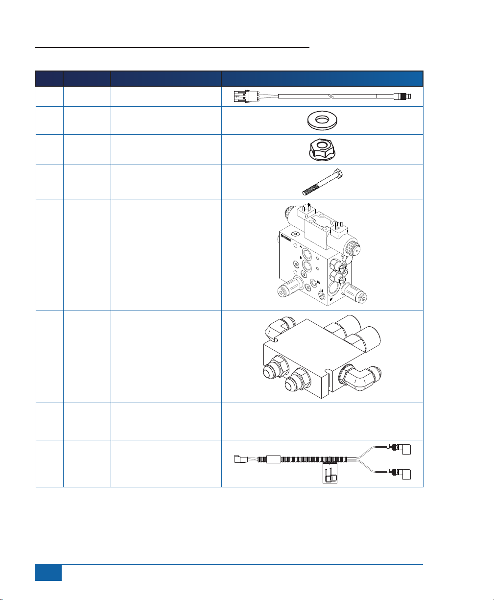
Unpack the installation kit and identify the required parts.
Item Part Number Description Quantity
A 32-04040 Switch, Engage/Disengage ......................................................................................1
B 350-0024 Washer, Flat, 1/4” SST .............................................................................................4
C 350-0083 Nut, Whiz-Lock, 1/4”-20 SST ..................................................................................2
D 350-0136 Bolt Hex, 1/4”-20 X 2-1/2” SST ................................................................................2
E 35-02182 Valve, FLDPLT, PWM OC, 4.0GPM .........................................................................1
F 35-02155 Valve Counter Balance ............................................................................................1
G 45-07703 Harness, SCM .........................................................................................................1
H 45-10103 Harness, Valve .........................................................................................................1
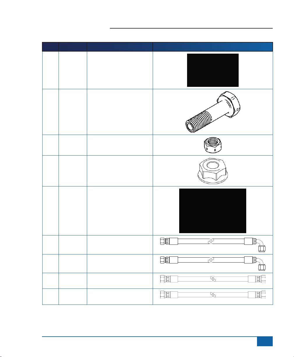
I 60-04089 Bolt Hex, 3/8”-16 X 3-3/4” SST ..............................................................................2
J 60-04091 Bolt Hex, 5/8”-11 X 1.5” SST ...................................................................................1
K 60-07027 Nut, NyLock 3/8-16, SST .........................................................................................2
L 60-07028 Nut, Whiz-Lock, 5/8”-11 SST ...................................................................................1
M 65-05134 Bracket, Hyd. Block Mnt - .......................................................................................1
N 68-01144 Hose, Hyd - 1/2” x 47”, #8FJIC x #8FJIC 90º ..........................................................1
O 68-01222 Hose, Hyd - 1/2” x 22”, #8FJIC x #8FJIC 90º ..........................................................2
P 68-01223 Hose, Hyd - 1/2” x 25”, #8FJIC x #8FJIC .................................................................2
Q 68-01224 Hose, Hyd - 1/2” x 32”, #8FJIC x #8FJIC .................................................................1
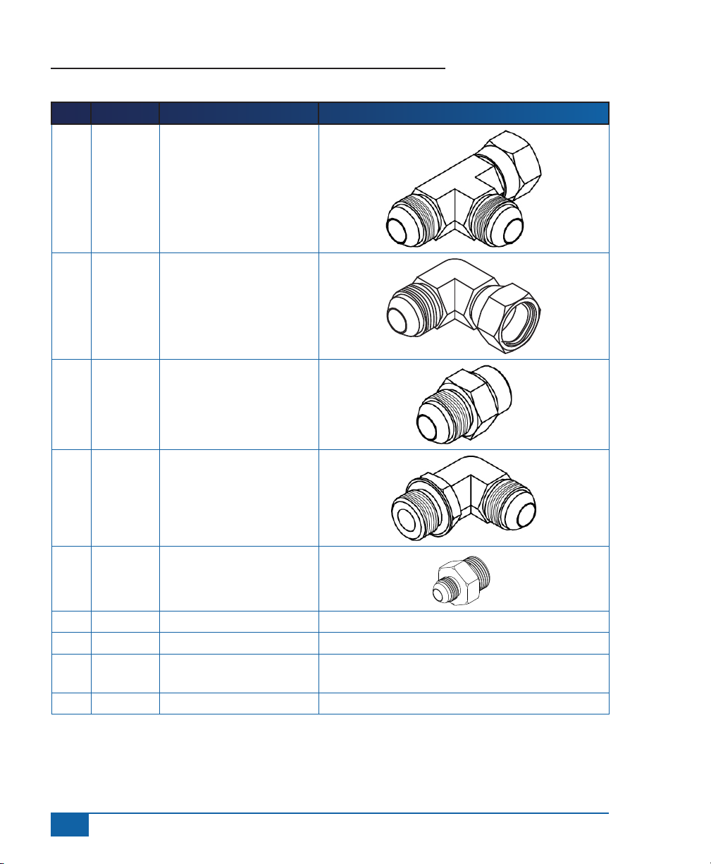
R 68-02009 Adapter, Hyd. Run Tee - #8 JIC ...............................................................................3
S 68-02093 Adapter, Hyd. 90º EL - #8MJIC x #8FJIC ................................................................5
T 68-02094 Adapter, Hyd. - #8MJIC x #8MORB .........................................................................5
U 68-02095 Adapter, Hyd. 90º EL - #8MJIC x #8MORB .............................................................2
V 68-02122 Adapter, Hyd. - #8MJIC x #12MORB .......................................................................2
W 90-50013 Cable Tie Kit, 15 ......................................................................................................1
X 91-07011 Steering Wheel Switch Kit .......................................................................................1
Y 98-05116 Installation Manual, AG-CHEM 1803 .......................................................................1
Z 16-00001 Magnets, Self-Adhesive .........................................................................................12
®
www.teejet.com
3
Page 5
FieldPilot
®
Item Part # Description Illustration
A 32-04040 Switch, Engage/Disengage
B 350-0024 Washer, Flat, 1/4” SST
C 350-0083 Nut, Whiz-Lock, 1/4”-20
SST
D 350-0136 Bolt Hex, 1/4”-20 X 2-1/2”
SST
E 35-02182 Valve, FLDPLT, PWM OC,
4.0GPM
F 35-02155 Valve Counter Balance
G 45-07703 Harness, SCM
H 45-10103 Harness, Valve
4
www.teejet.com
45-10103
DC:xx/xx
A
B
Page 6
Item Part # Description Illustration
I 60-04089
J 60-04091 Bolt Hex, 5/8”-11 X 1.5” SST
K 60-07027 Nut, NyLock 3/8-16, SST
L 60-07028 Nut, Whiz-Lock, 5/8”-11 SST
Bolt Hex, 3/8”-16 X 3-3/4”
SST
FieldPilot
®
M 65-05134 Bracket, Hyd. Block Mnt -
N 68-01144 Hose, Hyd - 1/2” x 47”,
#8FJIC x #8FJIC 90º
O 68-01222 Hose, Hyd - 1/2” x 22”,
#8FJIC x #8FJIC 90º
P 68-01223 Hose, Hyd - 1/2” x 25”,
#8FJIC x #8FJIC
Q 68-01224 Hose, Hyd - 1/2” x 32”,
#8FJIC x #8FJIC
www.teejet.com
5
Page 7
FieldPilot
Item Part # Description Illustration
R 68-02009 Adapter, Hyd. Run Tee - #8
S 68-02093 Adapter, Hyd. 90º EL -
T 68-02094 Adapter, Hyd. - #8MJIC x
®
JIC
#8MJIC x #8FJIC
#8MORB
U 68-02095 Adapter, Hyd. 90º EL -
#8MJIC x #8MORB
V 68-02122 Adapter, Hyd. - #8MJIC x
#12MORB
W 90-50013 Cable Tie Kit, 15
X 91-07011 Steering Wheel Switch Kit
Y 98-05116 Installation Manual, AG-
CHEM 1803
Z 16-00001 Magnets, Self-Adhesive
6
www.teejet.com
Page 8

Figure 1-1: Hydraulic Diagram
Hydraulics as installed
1803 s/n 1814366
Cummins engine
Eaton-Fuller Transmission
January 2008 WWR
O
FieldPilot
®
C1
Counterbalance
Valve 35-02155
V1
P P
T
C2
V2
P
O
A
35-02182
FieldPilot Valve
EF
N
B
T
P
New Hoses
SEC
PR
Q
www.teejet.com
7
Page 9

FieldPilot
®
8
www.teejet.com
Page 10

FieldPilot
INSTALLATION
If there are questions concerning the installation of the FieldPilot system on this vehicle, or due to
the changes in component specications the parts supplied in the kit are not exactly as presented
in this document, please contact your dealer or TeeJet Customer service representative for
clarication before installation. TeeJet Technologies is not responsible for misuse or incorrect installation of
the system.
NOTE: BE VERY CAREFUL TO ABSOLUTELY SECURE ALL CABLES AND HOSES SO THAT THEY
DON’T INTERFERE WITH THE MANY MOVING PARTS OF THE MACHINE!
1. PREPARE THE FIELDPILOT VALVE
Make sure the valve block is clean and dust free. Work on a clean bench. Remove the plastic plugs and
install the adapters (V) in the P and EF ports. Install adapters (S) on the ends of these.
Install two adapters (T) into the T, A and B ports. Install adapters (S) on the ends of these.
NOTE: All references to left and right are stated as if the user is seated in the driver’s seat.
Figure 1-2: Preparing Hydraulic Control Block
T
®
V
T
T
V
S
S
S
S
S
www.teejet.com
9
Page 11

FieldPilot
®
2. INSTALL MOUNTING BRACKETS ON FIELDPILOT VALVE.
Using the bolts and nuts (I and K) attach the valve block to the bracket (M) so that the ribbed part of the
bracket is pointed away from the valve block.
Figure 1-3: Install the Mounting Bracket
3. MOUNT VALVE BRACKET ON VEHICLE
The valve is mounted on the rear face of the tool cabinet located on the left side of the vehicle. Hold the valve
and bracket assembly in place to ensure clearance for the hoses (which will be attached later) and to position
the valve so it does not protrude outside the clearance of the tool box. Use the position of this assembly to
choose the best place to drill a hole in the forward face of the toolbox. Drill a single hole large enough to
accept the 5/8 inch mounting bolt (J), 11/16” is recommended.
Use the 5/8-11 x 1.5” bolt and Nyloc nut (J and L) to rmly attach the valve and bracket assembly to the
toolbox.
Figure 1-4: Mount Valve Bracket on Vehicle
10
www.teejet.com
Page 12

FieldPilot
®
4. PREPARE COUNTERBALANCE VALVE (B) BLOCK
Make sure the valve block is clean and dust free. Work on a clean bench. Remove the plastic plugs and
install the straight ttings (T) in ports C1 and C2. Install the elbow adapter ttings (U) in ports V1 and V2.
Orient the elbow adapters so that they are pointing the opposite direction from the ttings in ports C1 and C2.
Install #8 JIC Run Tee ttings (R) on the straight adapters in ports C1 and C2.
Figure 1-5: Prepare Counterbalance Valve Block
U
U
T, R T, R
www.teejet.com
11
Page 13

FieldPilot
®
5. MOUNTING THE COUNTERBALANCE VALVE
Hold the valve in position on the front of the left side of the cab. Check to be sure the hoses from both the
orbital and the FieldPilot Valve (E) will reach the correct ports on the counterbalance. Mark the bolt holes
and drill two 5/16 holes through the cab. Be sure to check for obstructions inside the cab.
Figure 1-6: Mounting The Counterbalance Valve
Bolt Holes
Using the bolts, washers, and nuts (B, C, and D) attach the valve block to the front of the cab as shown.
Once the valve assembly is mounted, the straight ttings in C1 and C2 should be facing toward the outside of
the vehicle with the center tap of the Run Tees facing forward. The elbow adapter ttings in V1 and V2 should
be facing toward the engine compartment.
Figure 1-7: Mounting the Counterbalance Valve, Continued
12
www.teejet.com
Page 14

FieldPilot
®
6. PREPARE PORTS ON STEERING ORBITAL VALVE
The Pressure and Tank ports on the steering orbital valve are the two ports on the top of the steering orbital
valve. The Tank port is the one closest to the rewall of the cab. The left and right steering orbital valve ports
are underneath the Pressure and Tank ports.
Figure 1-8: Steering Output Valve
Remove the hoses from the left and right steering ports. Place a temporary cap over these (#8 MJIC ttings)
and plugs in the ends of the hoses. Temporarily remove the hose from the T port and install a # 8 JIC Run
Tee (R) on the adapter tting on the T port. Reconnect the original hose from the T port to the end of this
Run Tee.
Figure 1-9: Mounting The Counterbalance Valve
Run Tee on the
Tank Port
www.teejet.com
13
Page 15

FieldPilot
®
7. FIELDPILOT VALVE HOSE CONNECTIONS
The Pressure port of the FieldPilot Valve (E) will be connected to the PR port on the steering pump. Refer
to the hydraulic system diagram Figure 1-1 to understand where the FieldPilot Valve (E) should t in the
system.
Figure 1-10: Pressure Line Connection
Hose removed from
PR port of the pump
Pressure
Excess Flow
Remove the hose from the PR port on the pump. This hose is then connected to the EF port of the FieldPilot
Valve (E). Install hose (Q) between the PR port on the pump and the P port on the FieldPilot Valve (E).
Figure 1-11: PR Port of the Steering Pump
14
www.teejet.com
PR port on the
steering pump
Page 16

FieldPilot
Install hose (N) to the T port of the FieldPilot Valve (E). Install the #8, 90° end of the hose to the branch of
the Run Tee, previously installed on the T port of the orbital steering valve.
Figure 1-12: Tank Return Hose
N
Install hoses (O) to the A and B ports of the FieldPilot Valve (E). The 90° ends of hoses (O) are routed up
to the counterbalance valve (F).
Figure 1-13: Tank Return Hose (Continued)
®
T Port
A and B Ports
www.teejet.com
15
Page 17

FieldPilot
®
8. INSTALL STEERING OUTPUT HOSES TO
THE COUNTERBALANCE VALVE
Hoses (P) are rst connected to the left and right steering ports on the orbital steering valve with the other
end connected to ports V1 and V2 of the counterbalance valve (F). The two hoses (O) from the A and B
ports of the FieldPilot Valve (E) are now connected to the ends of the Run Tee adapters installed on ports
C1 and C2 of the counterbalance valve (F). Finally, the two original hoses removed from the left and right
steering ports on the orbital steering valve are connected to the branches of the two Run Tee ttings on the
C1 and C2 ports of the counterbalance valve (F).
Figure 1-14: Install Steering Output Hoses
V2
C2
C1
V1
This completes the hydraulic kit installation. Be sure all ttings are tight and all hoses are supported Also
ensure there are no chafe points in the hose runs.
16
www.teejet.com
Page 18

FieldPilot
9. INSTALL STEERING DISENGAGE SENSOR
The steering disengage kit (X) along with item (Z) is used to automatically disengage FieldPilot when the
steering wheel is turned. The magnets mount to the steering as shown. The sensor must be mounted with a
1/8” clearance from the magnets.
Figure 1-15: Install Steering Disengage Sensor
Z
X
®
www.teejet.com
17
Page 19

FieldPilot
®
10. INSTALLATION OF ENGAGE/DISENGAGE SWITCH
Connect item (A) to the connector on the SCM harness labeled Remote Engage/Disengage. Install the push
button in a location that is easily accessible during operation of the machine. This switch (A) is not required
if the optional foot switch 32-04020 is used.
Figure 1-16: Engage/Disengage Switch
11. INSTALL THE VALVE CONTROL CABLE
Install the electronic valve control cable at the FieldPilot valve by attaching the DIN connectors to the
individual coils. Connect wire A to the left hand solenoid and wire B to the right hand solenoid.
NOTE: If the vehicle automatically steers the wrong way when tested, exchange the connector positions.
Route this cable under the cab and then into the cab through one of the exposed holes in the compartment
on the right rear of the cab. Secure the cable with wire ties as necessary.
18
www.teejet.com
Page 20
FieldPilot
12. RECOMMENDED ELECTRONICS INSTALLATION
The Steering Control Module (SCM) should be mounted securely to the oor of the cab. A good location
is to the right of the seat near the rear of the cab. The control console can be mounted to the operator’s
preference. The GPS antenna should be mounted as far forward as possible on top of the cab on a metal
surface of at least 4” square.
Figure 1-17: Recommended Electronics Installation
Console
®
GPS Antenna
www.teejet.com
19
Page 21

FieldPilot
®
13. VERIFY OPERATION OF HYDRAULICS
AND SET THE STEERING CONTROL RATE
Clean and pick up the area around the vehicle and make certain that it is safe to operate. Start the engine
and check hydraulic connections for leaks. Rotate the steering wheel from one extreme to the other and back
to center, check for leaks. While steering through the extremes of movement, check the cables and hoses for
wear points and strain, adjust as necessary.
The oil ow rate adjustment is accomplished through the Matrix console. The
target lock to lock time is 7 seconds. Refer to the Matrix manual for further
instructions.
Use the electronic steering control console to perform the left to right steering test. Count the seconds to
move the wheels from full left to full right and also in the opposite direction. The vehicle should be moving
forward very slowly during these tests so there is not excessive side pressure on the tires. If you nd that the
machine steers in the opposite direction from that being commanded in this steering test sequence, switch
the valve connectors at the FieldPilot valve.
NOTE: To activate the manual overrides, a tool such as a small screwdriver or allen wrench must be inserted
into the end of the coil to depress the override button.
WARNING: PINCH POINT HAZARD! To prevent serious injury or death, avoid unsafe practice
while manually operating hydraulic steering circuits. Keep others away and stay clear of
mechanical steering linkages.
14. COMPLETE ELEC TRONIC INSTALLATION
Refer to the owner’s manual supplied with the automated steering system to complete the electronic
installa¬tion and setup.
20
www.teejet.com
Page 22

F I E L D P I L O T®
U S E R M A N U A L
A series of equipment-specic hydraulic installation kits have been developed
to work in conjunction with your assisted steering system. This kit contains the
necessary components and instructions to install assisted steering hydraulics on the
AgChem (AGCO) TerraGator 1803 Floater Chassis (when equipped with Cummins
engine and Eaton-Fuller Transmission). Please review this manual thoroughly
before beginning the installation process.
1801 Business Park Drive
Springeld, Illinois 62703 USA
Tel: (217) 753-8424 • Fax: (217) 753-8426
www.teejet.com
98-05116 R2
© TeeJet Technologies 2010
 Loading...