

Page 1
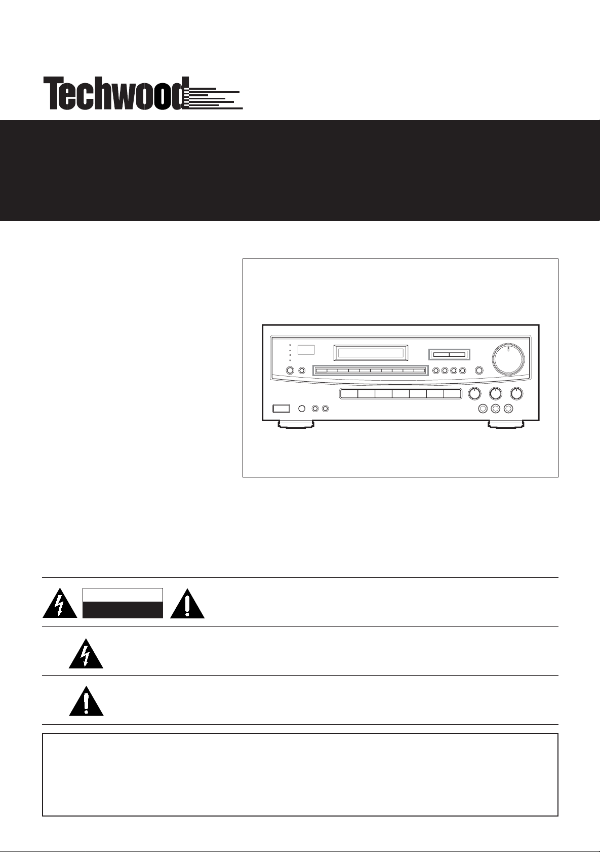
STR-8
4
260 WATT STEREO RECEIVER
OWNER’S MANUAL
CAUTION
RISK OF ELECTRIC SHOCK
DO NOT OPEN
The lightning flash with arrowhead symbol, within an equilateral triangle, is intended to alert the user
to thepresence of uninsulated “dangerous voltage” within the product’s enclosure that may
be of sufficient magnitude to constitute a risk of electric shock to persons.
The exclamation point within an equilateral triangle is intended to alert the user to the
presence of important operating and maintenance (servicing) instructions in the literature accompanying the appliance.
WARNING: TO PREVENT FIRE OR SHOCK HAZARD, DO
NOT EXPOSE THIS APPLIANCE TO RAIN OR
CAUTION: TO REDUCE THE RISK OF ELECTRIC SHOCK, DO NOT
REMOVE COVER (OR BACK). NO USER-SERVICEABLE PARTS INSIDE.
REFER SERVICING TO QUALIFIED SERVICE PERSONNEL.
MOISTURE.
Page 2
IMPORTANT SAFETY INSTRUCTIONS
CAUTION:
Read all of these instructions.
•
• Save these instructions for later use.
• Follow all warnings and instructions marked on the audio
equipment.
1) Read instructions - All the safety and operating instructions
should be read before the product is operated.
2) Retain instructions - The safety and operating instructions should
be retained for future reference.
3) Heed Warnings - All warnings on the product and in the operating
instructions should be adhered to.
4) Follow Instructions - All operating and use instructions should be
followed.
5) Cleaning - Unplug this product from the wall outlet before cleaning.
Do not use liquid cleaners or aerosol cleaners. Use a damp cloth for
cleaning.
6) Attachments - Do not use attachments not recommended by the
product manufacturer as they may cause hazards.
7) Water and Moisture -Donot use this product near water-for example, near a bath tub, wash bowl, kitchen sink, or laundry tub; in a wet
basement; or near a swimming pool; and the like.
8) Accessories - Do not place this product on an unstable cart, stand,
tripod, bracket, or table. The product may fall, causing serious injury to
a child or adult, and serious damage to the product. Use only with a
cart, stand, tripod, bracket, or table recommended by the manufacturer, or sold with the product. Any mounting of the product should follow
the manufacturer’s instructions, and should use a mounting accessory
recommended by the manufacturer.
9) A product and cart combination should be moved with care. Quick
stops, excessive force, and uneven surfaces may cause the product
and cart combination to overturn.
10) Ventilation - Slots and openings in the cabinet are provided for
ventilation and to ensure reliable operation of the product and to protect it from overheating, and these openings must not be blocked or
covered. The openings should never be blocked by placing the product on a bed, sofa, rug, or other similar surface. This product should
not be placed in a built-in installation such as a bookcase or rack
unless proper ventilation is provided or the manufacturer’s instructions
have been adhered to.
11) Power Sources - This product should be operated only from the
type of power source indicated on the marking label. If you are not
sure of the type of power supply to your home, consult your product
dealer or local power company. For products intended to operate from
battery power, or other sources, refer to the operating instructions.
12) Grounding or Polarization - This product may be equipped with
a polarized alternating-current line plug (a plug having one blade wider
than the other). This plug will fit into the power outlet only one way.
This is a safety feature. If you are unable to insert the plug fully into the
outlet, try reversing the plug. If the plug should still fail to fit, contact
your electrician to replace your obsolete outlet. Do not defeat the safety purpose of the polarized plug.
13) Power-Cord Protection - Power-supply cords should be routed
so that they are not likely to be walked on or pinched by items placed
upon or against them, paying particular attention to cords at plugs,
convenience receptacles, and the point where they exit from the product.
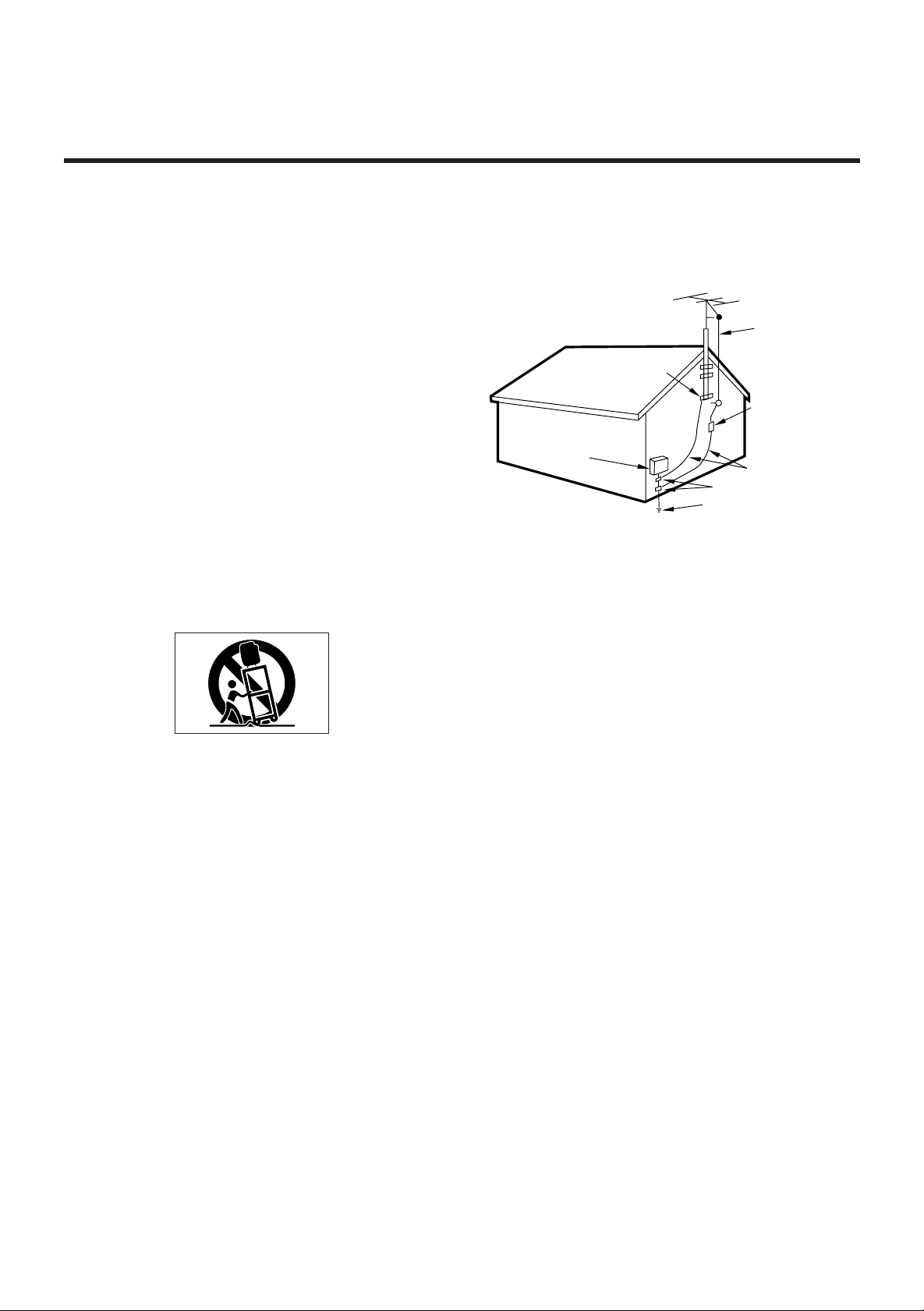
14) Outdoor Antenna Grounding - If an outside antenna or cable
system is connected to the product, be sure the antenna or calbe system is grounded so as to provide some protection against voltage
surges and built-up static charges. Article 810 of the National Electrical
Code, ANSI/NFPA 70, provides information with regard to proper
grounding of the mast and supporting structure, grounding of the leadin wire to an antenna discharge unit, size of grounding conductors,
location of antenna-discharge unit, connection to grounding electrodes, and requirements for the grounding electrode.
“Note to CATV system installer:
This reminder is provided to call the CATV system installer’s attention
to Section 820-40 of the NEC which provides guidelines for proper
grounding and, in particular, specifies that the cable ground shall be
connected to the grounding system of them building, as close to the
point of cable entry as practical.
Example of Antenna Grounding as per
National Electrical Code, ANSI/NFPA 70
GROUND
CLAMP
ELECTRIC
SERVICE
EQUIPMENT
NEC-NATIONAL ELECTRICAL CODE
POWER SERVICE GROUNDING
ELECTRODE SYSTEM
(NEC ART 250,PART H)
ANTENNA
LEAD IN
WIRE
ANTENNA
DISCHARGE UNIT
(NEC SECTION 810-20)
GROUNDING CONDUCTORS
(NEC SECTION 810-21)
GROUND CLAMPS
15) Lightning -For added protection for this product during a lightning
storm, or when it is left unattended and unused for long periods of
time, unplug it from the wall outlet and disconnect the antenna or cable
system. This will prevent damage to the product due to lightning and
power-line surges.
16) Power Lines -An outside antenna system should not be located in
the vicinity of overhead power lines or other electric light or power circuits, or where it can fall into such power lines or circuits. When
installing an outside antenna system, extreme care should be taken to
keep from touching such power lines or circuits as contact with them
might be fatal.
17) Overloading - Do not overload wall outlets, extension cords, or
integral convenience receptacles as this can result in a risk of fire or
electric shock.
18) Object and Liquid Entry - Never push objects of any kind into
this product through openings as they may touch dangerous voltage
points or short-out parts that could result in a fire or electric shock.
Never spill liquid of any kind on the product.
19) Servicing - Do not attempt to service this product yourself as
opening or removing covers may expose you to dangerous voltage or
other hazards. Refer all servicing to qualified service personnel.
20) Damage Requiring Service - Unplug this product from the wall
outlet and refer servicing to qualified service personnel under the following conditions:
a) When the power-supply cord or plug is damaged.
b) If liquid has been spilled, or objects have fallen into the product.
c) If the product has been exposed to rain or water.
d) If the product does not operate normally by following the operating
instructions. Adjust only those controls that are covered by the operating instructions as an improper adjustment of other controls may result
in damage and will often require extensive work by a qualified technician to restore the product to its normal operation.
e) If the product has been dropped or damaged in any way.
f) when the product exhibits a distinct change in performance-this indi-
cates a need for service.
21) Replacement Parts - When replacement parts are required, be
sure the service technician has used replacement parts specified by
the manufacturer or have the same characteristics as the original part.
Unauthorized substitutions may result in fire, electric shock, or other
hazards.
22) Safety Check - Upon completion of any service or repairs to this
product, ask the service technician to perform safety checks to determine that the product is in proper operating condition.
23) Wall or Ceiling Mounting - The product should be mounted to a
wall or ceiling only as recommended by the manufacturer.
24) Heat -The product should be situated away from heat sources
such as radiators, heat registers, stoves, or other products (including
amplifiers) that produce heat.
2
Page 3

CONTENTS
IMPORTANT SAFETY INSTRUCTIONS.........................................................................................................................................2
PRECAUTIONS ...............................................................................................................................................................................4
Read This Before Operating........................................................................................................................................................4
CONNECTIONS...............................................................................................................................................................................5
System Connections....................................................................................................................................................................5
Antenna Connections...................................................................................................................................................................6
FM Antenna ............................................................................................................................................................................6
AM (MW) Antenna ..................................................................................................................................................................6
Speaker Connections ..................................................................................................................................................................7
Power Cord .................................................................................................................................................................................7
AC OUTLETS ..............................................................................................................................................................................7
VIDEO 3 INPUT Jacks.................................................................................................................................................................7
CONTROLS AND INDICATORS.....................................................................................................................................................8
Front Panel ..................................................................................................................................................................................8
Display.......................................................................................................................................................................................10
REMOTE CONTROL UNIT............................................................................................................................................................11
Using the Remote Control Unit..................................................................................................................................................11
Battery Installation .....................................................................................................................................................................11
Remote Control Unit ..................................................................................................................................................................12
AUDIO OPERATIONS...................................................................................................................................................................13
Back-up memory function..........................................................................................................................................................13
Sleep Timer Oepration...............................................................................................................................................................13
When to use reset switch...........................................................................................................................................................13
Basic Operations........................................................................................................................................................................14
Audio Adjustments.....................................................................................................................................................................14
Radio Reception ........................................................................................................................................................................15
Auto Tuning...........................................................................................................................................................................15
Manual Tuning.......................................................................................................................................................................15
Direct Tuning with Remote Control .......................................................................................................................................16
Preset Tuning.............................................................................................................................................................................17
Automatic Memory Presetting ...............................................................................................................................................17
Manual Memory Presetting ...................................................................................................................................................17
Listening to Records and Compact Discs..................................................................................................................................18
Playing Tapes............................................................................................................................................................................18
Recording a Source...................................................................................................................................................................18
VIDEO OPERATIONS....................................................................................................................................................................19
Playing Video sources ...............................................................................................................................................................19
Recording with a video deck......................................................................................................................................................19
Tape Dubbing (from VIDEO 2 to VIDEO 1)...........................................................................................................................19
Video Editing Function ..........................................................................................................................................................19
TROUBLESHOOTING...................................................................................................................................................................20
SPECIFICATIONS .........................................................................................................................................................................21
3
Page 4

PRECAUTIONS
Read This Before Operating
Choose the installation location of your unit carefully.
Avoid placing it in direct sunlight or close to a source of
heat. Also avoid locations subject to vibrations and
excessive dust, heat, cold or moisture.
The ventilation holes should not be covered. Make sure
there is at least 20 cm (8 inches) of space above and at
least 5 cm (2 inches) of space beside the
amplifier/receiver. Do not place a CD player or other
equipment on top of the amplifier/receiver.
Do not open the cabinet as this might result in
damage to the circuitry or electrical shock. If a foreign
object should get into the set, contact your dealer.
When removing the power plug from the wall outlet,
always pull directly on the plug, never yank the cord.
Do not attempt to clean the unit with chemical
solvents as this might damage the finish. Use a
clean, dry cloth.
Keep this manual in a safe place for future refernce.
For U.S.A
TO THE USER
This equipment has been tested and found to
comply with the limits for a A/V receiver, pursuant to
Part 15 of the FCC Rules. These limits are designed to
provide reasonable protection against interference in
a residential area. This device generates and uses
radio frequency energy and if not installed and used in
accordance with the instructions, it may cause interference to radio or TV reception. If this unit does cause
interference with TV or radio reception you can try to
correct the interference by one or more of the
following measures :
a) Reorient or relocate the receiving antenna.
b) Increase the separation between the equipment and
the receiver.
c) Plug the equipment into a different outlet so that it is
not on the same circuit as the receiver.
If necessary, consult the dealer or an experienced
radio/TV technician for additional suggestions.
CAUTION
Changes or modifications to this equipment not
expressly approved by WELTON U.S.A. for compliance
could void the user’s authority to operate this
equipment.
The equipment draws nominal non-operating power
from the AC outlet with its POWER switch in the
STANDBY position.
For CANADA AND U.S.A.
AC POWER CORD CONNECTION
CAUTION :
TO PREVENT ELECTRIC SHOCK, MATCH WIDE
BLADE OF PLUG TO WIDE SLOT, FULLY INSERT.
ATTENTION
Pour éviter les chocs électriques, Introduire la lame la
plus large de la fiche dans la borne correspondante de
la prise et pousser jusqu’au fond.
4
Page 5
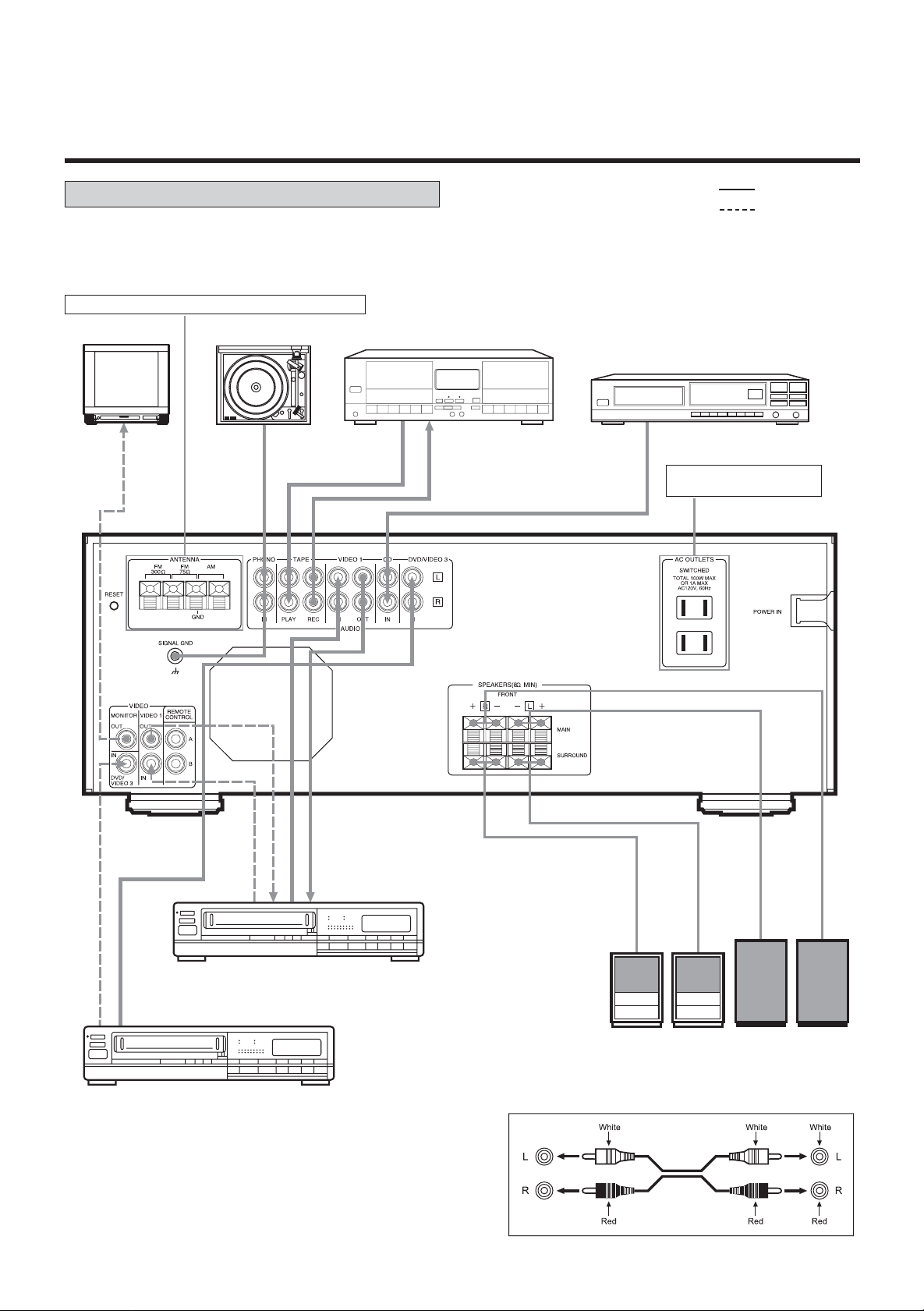
CONNECTIONS
System Connections
CAUTION : Do not plug the power cord of any
component into AC outlets and do not turn their POWER
switches on until all connections have been performed.
Refer to “Antenna Connections” on pages 6~7.
TV Monitor
Turntable
Tape Deck
LINE OUT
LINE IN
: Audio signal
: Video signal
CD Player
AC Outlets:
Two switched, Total 100W.
VIDEO OUT
AUDIO OUT
VIDEO 1
VIDEO IN
AUDIO OUT
VIDEO OUT
DVD/VIDEO 3
AUDIO IN
REAR SURROUND
SPEAKERS
Audio connection cords
MAIN SPEAKERS
5
Page 6
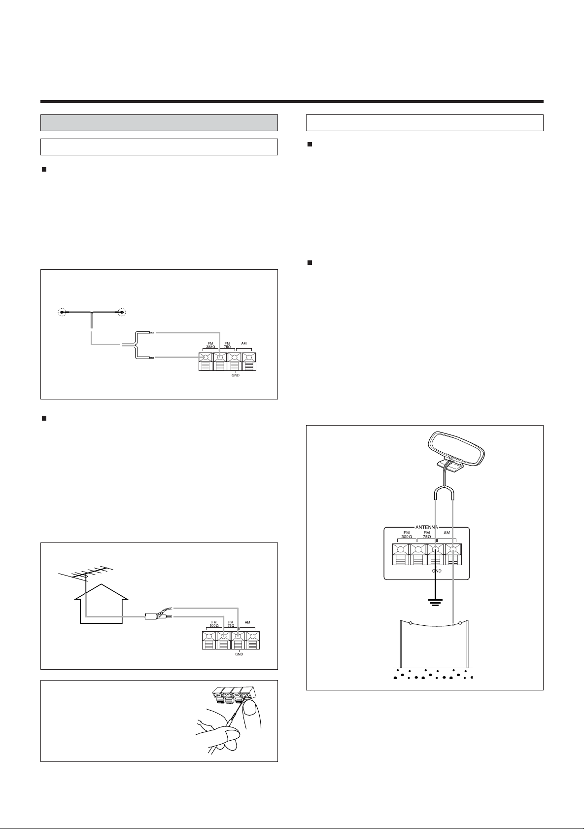
Antenna Connections
AM (MW) Antenna
FM Antenna
FM Indoor Antenna
In an area with strong FM signals, the “T“-type FM antenna
provided is sufficient. Extend this into a “T“ shape and connect the two wires at the base of the T to the antenna terminals , as shown. For details of how to connect the antenna
wires to the terminals, see the illustration.
Extend the top of the T and fix with thumb tacks, or the like,
to a wall or window frame for the best possible reception.
“T”-type FM Antenna
(300 )(provided)
FM Outdoor Antenna
In an area where FM signals are weak, it will be necessary
to use a 75-ohm unbalanced-type outdoor FM antenna.
Generally, a 3-element antenna will be sufficient; if you live
in an area where the FM signals are particularly weak, it
may be necessary to use one with 5 or more elements.
A 75-ohm antenna uses a coaxial cable and should be connected as follows: first strip the covering of the cable, then
twist the wire shielding so the inner core and shielding can
be connected as shown.
AM Indoor Loop Antenna
A high-performance AM loop antenna provided with the
receiver is sufficient for good reception in most areas.
Connect the loop antenna’s wires to the AM antenna terminals as shown. Place the antenna on a shelf, for
example, or hang it on a window frame, etc., in the direction which gives the best reception, as far away as possible from the entire system, speaker cords and the
power cord, to prevent unwanted noise.
AM Outdoor Antenna
If the AM loop antenna provided does not deliver sufficient reception (because you are too far from the transmitter or in a concrete building, etc.), it may be necessary to use an outdoor AM antenna. Use an insulated
wire more than 15 ft (5 m) long, strip one end, and connect this to the terminal as shown. The antenna wire
should be strung outdoors or indoors near a window.
For better reception, connect the GND terminal to a reli-
able ground.
Note : Even when using an outdoor AM antenna, do not dis-
connect the AM loop antenna.
AM Loop Antenna
(provided)
U.S.A/Canade/
General Export
Model
Outdoor FM Antenna (75 )
How to connect antenna
Press the lever, insert the
stripped and twisted end of the
wire, then release the lever so
that the wire is held securely.
AM Outdoor
Antenna
6
Page 7
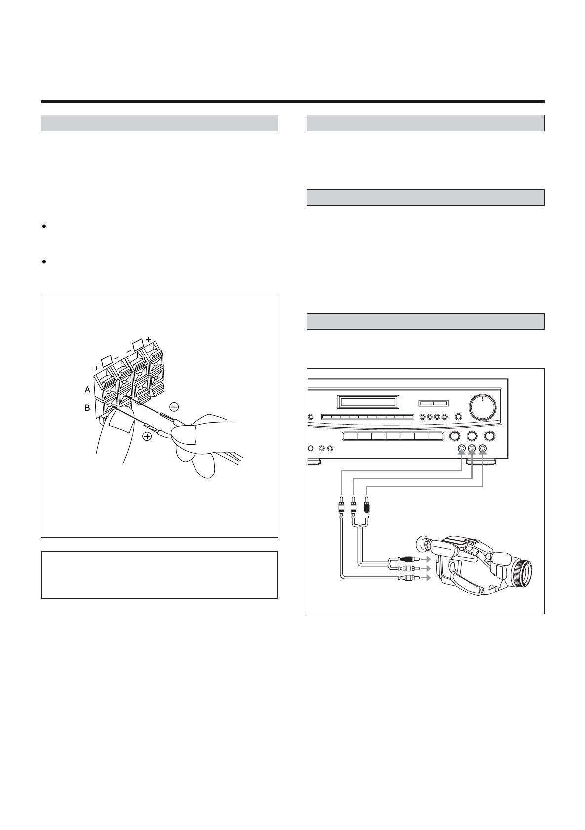
Speaker Connections
Power Cord
Caution :
To avoid damaging the speakers, be sure the power is off
before connecting the speakers.
Connect each speaker to the corresponding speaker
terminal.
Notes :
When using the rear speakers, be sure to connect them
to both channels (L and R). If a speaker is
connected to only one channel, no sound will be heard.
Use speakers with a nominal impedance of 8 ohms or
more.
How to connect the speaker cords
L
R
Be sure to connect the power cord to an AC outlet which
supplies the correct 120 voltage.
AC OUTLETS
SWITCHED :
These outlets switch on and off when you turn the amplifier
on and off.
Caution :
The total power consumption of the components connected
to the AC OUTLETS must not exceed 100W.
VIDEO 3 INPUT Jacks
Video camera or other video components may be connected
to the video 3 input jacks on the front panel.
Press the lever, insert the stripped and twisted end
(approx. 10 mm) of the cord, then release the lever so
that the cord is held securely.
IMPORTANT : One of the MAIN/SURROUND speaker
selectors on the front panel must be
turned on or no sound will be heard.
AUDIO
OUT
VIDEO OUT
Video Camera Recorder, etc.
7
Page 8

CONTROLS AND INDICATORS
Front Panel
1. STANDBY/ ON button and Indicator
When in standby mode, a red indicator will light up.
When you press the POWER button, power will be turned
on and the green indicator will light up.
2. LINE STRAIGHT button and Indicator
Press this button to bypass the bass and treble tone control, and surround mode. The indicator will light up.
Press the button again to release it.
3. SPEAKER selector buttons
These buttons are used to select the speaker system
“MAIN” or “SURROUND”. The corresponding LED light
will be turned on.
4. REMOTE SENSOR
5. DISPLAY
6. LOUDNESS
When listening at a low volume level, you can press
this switch to boost bass.
Press the switch again to release it.
IMPORTANT :
Never activate the loudness button when playing
the stereo above the 50% volume level or damage
will occur to your speakers and stereo.
7. MASTER VOLUME
8. TREBLE control
Use to adjust high frequency response.
9. BASS control
Use to adjust bass response.
10. BALANCE control
Use to balance volume between the left and right main
speakers.
11. VIDEO 3 Audio and Video terminal
For connection of portable video component such as a
camcorder.
12. INPUT SOURCE selector
PHONO :
Press to listen to a record on optional turntable.
“PHONO“ appears in the display.
TUNER :
Press to listen to a radio broadcast.
TAPE MONITOR :
Press to listen to a tape.
“TAPE M“ appears in the display.
CD :
Press to listen to a CD.
“CD“ appears in the display.
VIDEO 1 :
Press when playing a video component connected
to this input.
“VIDEO 1“ appears in the display.
VIDEO 2 :
Press when playing a video component connected
to this input.
“VIDEO 2“ appears in the display.
DVD/VIDEO 3 :
Press when playing a video component connected to
this input.
“DVD“ appears in the display.
13. HEADPHONE jack for optional headphones.
8
Page 9

14. SLEEP button
15. Preset buttons (0 -9)
These buttons are used to store and recall FM/AM stations in memory (See page 17).
16. MEMORY button
Use to store FM/AM stations in memory (See page 17).
17. MODE button
Use to select the Normal Tuning Scan or Preset Channel
scan modes.
See Radio Reception (See page 15 ~ 17).
18. TUNING/PRESET buttons
See Radio Reception (See page 15 ~ 17).
19. FM MODE button
When activated, this unit automatically switches into the
stereo mode when a stereo broadcast is received and
the stereo light illuminates.
Press this button again to listen in the mono mode.
The stereo indicator will not illuminate in the mono
mode.
20. BAND selector button
Each time you press the button, the bands will
change as follows.
FM AM
9
Page 10

Display
1. Input source, frequency and level indicator
Function display :
When you press input selection button, the selected input
source will be shown.
Frequency display :
When you select Tuner input source, FM/AM frequency
will be displayed.
Surround Sound Level display :
When you adjust the level of center, rear and delay when
operating unit in surround mode, the level will be displayed in dB.
2. Memory Channel indicator
The number of the memory channel which is selected
will be displayed.
3. MEMORY indicator
Press the MEMORY button and the MEMO indicatorwill light.
If you press the MEMORY button and release instantly,
the indicator will blink 4 times.
This method is used for manual station programming.
If you press the MEMORY button longer than 1/2
second, the indicator will remain lit until the automatic
programming is completed.
4. TAPE Monitor indicator
This indicator will illuminate When you press TAPE
MONITOR button.
5. STEREO indicator
This indicator will illuminate when FM stereo broadcasting
is received. The indicator will not light up on FM mono or
AM broadcasting.
6. TUNED indicator
This indicator will illuminate when a radio station is precisely tuned.
7. TIMER indicator
This indicator will illuminate when the timer is used.
10
Page 11

REMOTE CONTROL UNIT
Using the Remote Control Unit
By using the provided remote control unit, the receiver and
matched optional components CDC-85 and TDX-85 can be
controlled from your listening position.
To use the remote control unit, point it at the REMOTE
SENSOR window of the receiver.
REMOTE SENSOR window
of the receiver
Notes :
Even if the remote control unit is operated within the
effective range, remote control operation may be impossible if there are any obstacles between the unit and the
remote control.
If the remote control unit is operated near other
appliances which generate infrared rays, or if other
remote control devices using infrared rays are used near
the unit, the stereo may operate incorrectly. Converseiy,
the other appliances may also operate incorrectly.
Battery Installation
1. Remove the battery compartment cover.
2. Insert two “AAA” (R03, UM-4) dry batteries.
Make sure that the batteries are inserted with their positive and negative poles positioned correctly.
3. Close the cover until it clicks.
Battery Replacement
If the distance required between the remote control unit
and main unit decreases, the batteries are exhausted. In
this case replace the batteries with new ones.
Precautions concerning batteries
Be sure to insert the batteries with correct positive “ ”
negative “ ” polarities.
Use batteries of the same type. Never use different types
of batteries together.
Rechargeable and non-rechargeable batteries can be
used. Refer to the precautions on their labels.
When the remote control unit is not to be used for a long
time (more than a month), remove the batteries from the
remote control unit to prevent them from leaking. If they
leak, wipe away the liquid inside the battery compartment
and replace the batteries with new ones.
Do not heat or disassemble batteries and never
dispose of old batteries by throwing them in a fire.
and
11
Page 12

Remote Control Unit
POWER SELECTION
1. POWER ON button
2. POWER STANDBY button
TUNER SECTION
3. SLEEP button
4. TUNING UP/DOWN buttons
5. P.CALL UP/DOWN buttons
6. NUMERIC keys
7. BAND selector button
8. DIRECT TUNING button
AMP SECTION
9. INPUT SOURCE Selector buttons
10. MUTING button
11. MASTER VOLUME CONTROL
(VOLUME up/down buttons)
Certain buttons on the remote control unit and on the front
panel of the receiver have the same or similar functions and
have the same reference numbers.
DECK SECTION
12. TAPE DECK Operation buttons
(For use with optional matched tape deck TDX-85).
CD SECTION
13. CD Player Operation buttons
(For use with matched compact disc changer CDC-85).
12
Page 13

AUDIO OPERATIONS
Back-up memory function
BACK-UP memory
This function stores the preset memory and most-recent
memory functions. In the event of a power failure, or if the
power cord of this unit is disconnected from the electric outlet, the back-up memory will save the preset memory and
most-recent memory functions for approximately 3 days.
If the power supply is interrupted for 3 days or longer, the
memory settings will be erased.
Sleep Timer Operation
SLEEP Timer Function
This function allows you to preprogram the receiver to
switch the power off automatically.
You can enjoy the audio/video system for a specified
amount of time without having to worry about turning the
unit off later.
Each press of the SLEEP button changes the time indication by 10 minutes.
SLEEP 90 SLEEP 80 • • • SLEEP 10
(No timer setting)
To determine how much time remains after the sleep
timer has been set, press the sleep button again, the
remaining time will be displayed.
To turn the sleep timer off after it has been set, press the
sleep button repeatedly until the timer counts down and
the tuner display lights up with radio frequency.
WHEN TO USE RESET SWITCH
Ocassionally, the microprocessor inside the unit may malfunction due to electrical power surges or lightning storms. If
the unit or display malfunctions, try resetting the microprocessor as shown.
RESET SWITCH
Press the RESET switch lightly once or twice with a
pencil or a ballpoint pen.
Note : When the RESET switch is pressed, all the
memory will be cancelled.
IMPORTANT NOTE :
The following applies through out the “AUDIO and
VIDEO OPERATIONS” sections unless otherwise noted.
To simplify explanations, instructions refer to names of
buttons and controls on the front panel, making no
mention of the use of remote control unit.
To listen to a source other than tape deck, press the
TAPE MONITOR button to the OFF position (the
TAPE monitor indicator will not light in the display).
-Rear PANEL-
13
Page 14

Basic Operations
1. Set the MASTER VOLUME control to “0”. This is to protect the speakers from a sudden high-level signal.
2. Set the LOUDNESS button to the OFF position.
3. Adjust the tone as required with the BASS and TREBLE
tone controls. Adjust the balance between the left and
right channels with the BALANCE control.
4. Press the POWER button to ON.
5. Select the desired source with the source selector.
6. Select the speaker system to be used with the
SPEAKERS select buttons.
With the unit, speakers “MAIN” and “SURROUND” can be
selected simultaneously.
7. Start playing the source component.
8. Gradually turn up the volume to the required level with
the MASTER VOLUME control.
Audio Adjustments
POWER STANDBY / ON Button
Press this button to turn the power on.
Press it again to turn the system off (power standby mode).
The indicator lights up in power standby mode and goes out
when this unit is turned on.
SPEAKERS Select Buttons
These buttons are used to select speaker system MAIN or
SURROUND.
LINE STRAIGHT Button
When this button is pressed, the signal selected by the
source selector buttons is supplied directly to the amplifier circuit, allowing you to listen to the source with better sound
quality. When the LINE STRAIGHT mode is selected, the
BASS, TREBLE controls will be defeated. This feature
allows the addition of a frequency equalizer.
BASS/TREBLE Tone Controls
These two tone controls-BASS and TREBLE-can be used to
obtain a “flat” frequency response or a tone which suits your
individual listening preference. The Bass control adjusts low
frequencies and the TREBLE control adjusts the high frequencies.
IMPORTANT :
One of the MAIN/SURROUND speaker selectors must
be turned on or no sound will be heard.
BALANCE Control
This control is used to adjust the balance between the left
and right channels. Normally set to the center position.
LOUDNESS Button
This button compensates for the non-linear response of the
human ear at low volumes. Set this switch to the OFF position when listening at levels of 50% or higher.
MUTING Button (on the Remote Control Unit)
Press this to mute (-20dB) the sound from the speakers and
headphones when answering the telephone, etc.
To restore the original volume, press the MUTING button
again. While muting is engaged, the MASTER VOLUME
level indicator will flicker.
14
Page 15

Radio Reception
Manual Tuning
Auto Tuning
1. Press the TUNER input selector.
2. Select AM or FM by pressing the BAND selector button.
3. Press the MODE button to select the normal TUNING
mode.
This button is used to select normal Tuning or Preset
Channel Scan modes. For normal tuning, the PRESET CH
indicator light should be off.
Manual Tuning is generally used to tune to stations broadcasting a signal that is too weak to be received by Auto
Tuning.
1. Press the TUNER input selector.
2. Select AM or FM by pressing the BAND selector button.
3. Press the MODE button to select normal TUNING Scan
mode.
(The PRESET CH. indicator disappears from the display).
4. When the UP or DOWN TUNING button is pressed
momentarily (1/2 second or less), the frequeny changes
by a fixed step (see STEPS below).
STEPS
FM : 100-kHz steps
AM : 10-kHz steps
4. Press and hold the UP or DOWN TUNING button
(between 1/2 to 2 seconds). The next station
broadcasting at a frequency higher or lower than
that of the current station is automatically detected and
tuned in.
• By pressing and holding the TUNING button for longer
than 2 seconds, it will continue to scan (three times
faster than normal speed).
FM MODE Button
Pressing this button alternates between Stereo mode
and Mono mode.
– Stereo
FM stereo broadcasts are received in stereo and the
STEREO indicator lights in the display.
Monophonic broadcasts are received in mono.
If FM broadcasts with weak signal strength are
received, the FM muting (-20dB) function works automatically to cut the signals, eliminating loud noise.
– Mono
To compensate for weak FM stereo reception, select
this mode. Reception will now be received in monaural, reducing unwanted noise.
TUNED Indicator
“TUNED” appears in the display when a broadcast is
correctly tuned in.
15
Page 16

Direct Tuning With Remote Control
You can tune a station directly by inputting the actual frequency using the remote control.
1. Press the TUNER button.
2. Select AM or FM by pressing the BAND selector button.
3. Press the DIRECT TUNING button on the remote control
unit, “ENTER FREQUENCY” appears on the display for a
few seconds.
“FM ---.---MHz” or “AM----KHz” appears on the display.
4. Input the frequency of the broadcast you want to hear
with the numeric keys.
If you press the DIRECT TUNING button again or without
pressing any button for 30 seconds, Direct tuning is
released.
FM : 100-kHz steps
AM : 10-kHz steps
Ex.: FM 87.7 MHz
8
7
7
Ex.: AM 1420 kHz
1 4 2
Note :
When inputting the frequency, the last digit need not be
entered as it is always “0”.
16
Page 17

Preset Tuning
3
2
1
This feature is used to store up to 30 FM, AM stations in
memory.
Automatic Memory Presetting
Manual Memory Presetting
1. Press the TUNER input selector.
1. Press the TUNER input selector.
2. Select AM or FM by pressing the BAND selector button.
3. Press the MEMORY button for more than 1.5 seconds.
The start frequency will show in the display.
• 87.5 MHz in FM, 530 kHz in AM.
The frequency and display will automatically scan.
• 100 kHz steps for FM, 10 kHz steps for AM.
The frequency shown in the display will rapidly change.
As each station is located a preset number will appear
in the display indicating which preset
MEMORY button has been assigned to the station locat-
ed. The scanning process will continue to operate until
30 stations have been found and entered into the preset
memory. When there are no more stations to be found
on the waveband chosen, the memory indicator will
extinguish and let you hear the last station to be memorized.
• To listen to a desired memorized station select the band
and press the numeric keys button 1, 2, 3 etc.
4. The last memorized channel of each band will be displayed when Auto Memory is completed. You can check
the programmed frequencies with PRESET UP and
DOWN button.
2. Select AM or FM by pressing the BAND selector button.
3. Press the MODE button to change to TUNING mode.
(The PRESET CH. indicator disappears from the display).
4. Select the frequency you want to preset by pressing UP
or DOWN tuning button.
5. Press the MEMORY button briefly, MEMORY display will
blink at an interval of 1 second.
6. While the MEMORY indicator is lit, press the numeric
key(s) to input the channel number for the station to be
stored (or press the PRESET button then press the
MEMORY button again).
Recalling Frequencies
Press the numeric key(s) corresponding to the channel
number to tune directly to a broadcast.
Using the Memory Scan function on the Remote
Control
When the MEMORY SCAN button is pressed, the preset
stations in which frequencies have been stored are
scanned at 5-second intervals. When you hear a broadcast
you want to listen to, turn the Memory Scan function off by
pressing the MEMORY SCAN button again.
17
Page 18

Listening to Records and Compact Discs
1.Press the PHONO or CD selector button.
2.Play the turntable or CD player.
Refer to the owner’s manual included with the player.
Recording a Source
Recording program source
You can record a program source such as a record or
Compact Disc onto a cassette deck connected to the TAPE
REC jacks.
IMPORTANT :
An optional phono turntable can be connected to the
STR-84. However the turntable must be equipped with
a magnetic type cartridge.
Playing Tapes
1. Make sure the TAPE MONITOR button is set to OFF,
then press the source selector button corresponding to
the source to be recorded.
2. Play the source.
3. Operate the tape deck for recording.
Tape Monitoring
If the tape deck has separate record and playback heads,
during recording, the recorded sound can be heard from
the speakers with the TAPE MONITOR button set to ON.
The TAPE M indicator will light when activated.
1. Set the TAPE MONITOR button to ON; the TAPE monitor
indicator will appear in the display.
2. Operate tape deck for playback.
Reter to the owner’s manual included with the tape deck.
18
Page 19

VIDEO OPERATIONS
Playing Video Sources
Recording with a Video Deck
Tape Dubbing (from VIDEO 2 to VIDEO 1)
1. Press the VIDEO 2 button with the TAPE MONITOR set
to OFF.
1. Press the VIDEO 1, VIDEO 2, or DVD/VIDEO 3 button.
2. Play the component corresponding to the button pressed.
3. The picture from the video souce can be seen on the TV
and the sound from the video source will be heard from
the speakers, provided both are properly connected to
the STR-84 as shown on page 5.
2. Operate VIDEO 2 for playback.
3. Operate VIDEO 1 for recording. In this way, the
video/audio signals from VIDEO 2 can be dubbed onto
VIDEO 1.
This feature will only operate if both video sources are
properly connected to the STR-84.
Video Editing Function
This feature lets you replace the sound from a VCR with
sound from an AUDIO source such as CD during video signal dubbing.
1. Press the DVD/VIDEO 3 (or VIDEO 2) button and operate DVD/VIDEO 3 (or VIDEO 2) for playback.
2. Select the audio source with the source selector buttons, and
then operate the selected audio component for playback.
3. Now you can watch the picture from the video
component on the TV, and listen to the sound from
the audio component through the speakers.
Note : Be sure to observe the order of steps 1 and 2.
4. Operate VIDEO 1 for recording. In this way, the Video
editing operation will be completed.
19
Page 20

TROUBLESHOOTING
To determine any problem with your receiver, always check the most obvious possible causes first. If any problem still remains
after your have checked the items below, consult your nearest TECHWOOD dealer.
Problem Probable Cause Remedy
Amplifier
When listening to the music in stereo,
left/right speakers sounds reversed.
Speakers are connected wrong.
After checking, if needed, reconnect.
Low hum or buzzer sound.
Sound is only heard from one channel.
Sound cuts off during listening to the
music or no sound even though power
is ON.
No sound.
Low bass response.
Tuner
An unusual hissing noise is heard when
listening to the broadcast in stereo, but
not heard when listening monaurally.
Noise is excessive in both stereo and
monaural broadcasts.
Sound is distorted and/or the volume
level becomes low.
Excessive distortion in the sound of
stereo broadcasts.
Power line of a fluorescent light is
installed near this product.
One of the input cords is disconnected.
The BALANCE control is set to one side.
Speaker impedance is less than
prescribed for this unit.
MAIN/SURROUND Speaker selectors
are turned off.
Speaker polarity (+/–) is reversed.
Line straight button is turned on.
A slight noise may be heard because the
method use for modulation of FM stereo
broadcasts is different than that used
for monaural broadcasts.
Poor location and/or direction of the
antenna.
Transmitting station is too far away.
Broadcast signals are being disturbed.
Speaker system connections are not
correct.
Place this product as far away as possible from electric devices with interference.
Connect the input cords securely.
Adjust the BALANCE control.
After turning off the power and then
turning it on again, reduce the volume or
change to the correct 8 ohm speakers.
Press the MAIN or SURROUND speaker selector as applicable.
Check all speakers for correct polarity.
Press the line straight button to turn off.
• Try reducing the treble sound by turning the treble controls.
•Try changing the location, height
and/or direction of the antenna.
•Set the FM mode to monaural by
pressing the STEREO/MONO button.
(Note that the broadcast will then be
heard as monaural sound).
• If an indoor antenna is being used,
change to an outdoor antenna.
• Try using an antenna with more elements.
Remote Control Unit
Remote control not working.
The batteries are exhausted.
The remote control unit is too far from
the receiver or out of the effective
range.
20
Replace with new batteries.
Operate the remote control unit
within the effective range.
Page 21

SPECIFICATIONS
Amplifier Section
Output Power (Front) :
F.T.C. Rating :
260 Watts total.
130 watts RMS per channel minimum, both channels
driven into 8 ohms from 20 Hz to 20 kHz with no more
than 0.9% total harmonic distortion(U.S.A./Canada)
Delay Time :
DOLBY PRO LOGIC : 15 ~ 30mS
HALL/THEATER : 15 ~ 50mS
Input Sensitivity/Impedance :
PHONO : 2.5 mV/47 k ohms
LINE : 220 mV/47 k ohms
Frequency Response :
PHONO : 20 Hz ~ 20kHz, ±1 dB
LINE : 10 Hz ~ 60 kHz, +1/ -3 dB
Signal-to-Noise Ratio :
PHONO : 65 dB (IHF-A)
LINE : 90 dB (IHF-A)
Tone Control :
BASS : ±10 dB at 100 Hz
TREBLE : ±10 dB at 10 kHz
FM Tuner Section
Tuning Range :
87.5 MHz ~ 108.0 MHz (100 kHz steps)
(U.S.A./Canada)
Usable Sensitivity (IHF) :
Mono : 15 dBf (U.S.A./Canada)
50 dB Quieting Sensitivity :
Mono : 23 dBf (U.S.A./Canada)
Stereo : 40 dBf (U.S.A./Canada)
Capture Ratio :
2.0 dB (U.S.A./Canada)
Image Rejection Ratio :
40 dB (U.S.A./Canada)
AM Suppression Ratio : 40 dB
Total Harmonic Distortion (1 kHz) :
Mono : 0.4%
Stereo : 0.5%
Frequency Response : 30 Hz ~ 15 kHz, +1/ -1.5 dB
Stereo Separation (1 kHz) : 40 dB
Signal-to-Noise Ratio :
Mono : 65 dB
Stereo : 60 dB
AM Tuner Section
Tuning Range :
530 kHz - 1,720 kHz (10 kHz steps)
(U.S.A./Canada)
Usable Sensitivity : 55 dB/m
Total Harmonic Distortion : 0.8% at 85 dB/m
Signal-to-Noise Ratio: 45 dB at 85 dB/m
Video Section
Input Sensitivity /Impedance : 1.0 Vp-p/75 ohms
Output Level /Impedance : 1.0 Vp-p/75 ohms
General
Power Requirements :
120 V AC, 60 Hz (U.S.A./Canada)
Power Consumption :
3.0 A (U.S.A./Canada)
AC Outlets :
Switched x 2, Total 100 W max. (1 A max.)
(U.S.A./Canada)
Dimensions (W x H x D) : 435 x 165 x 345 mm
Weight (net) : 20 lbs
Standard Accessories :
AM Loop Antenna x 1
FM “T” Type Antenna x 1
Remote Control Unit x 1
Owner’s manual x 1
AAA Batteries x 2
* LINE means CD, VIDEO 1, VIDEO 2, DVD/VIDEO 3 and
TAPE 1.
Improvements may result in specifications and
features changing without notice.
Illustrations may differ slightly from production
models.
21
Page 22

WELTON U.S.A.
11625 COLUMBIA CENTER DR. SUITE 100
DALLAS, TEXAS 75229
PHONE: 972-243-5602
FAX: 972-243-5958
KQX1A448Z
 Loading...