


DDR 95
AV Digital Surround Receiver
|
FUNCTION |
|
|
|
|
|
|
|
|
|
|
|
VOLUME |
|
|
|
|
|
|
|
|
|
|
|
|
|
|
DIGITAL |
|
|
|
|
|
|
|
|
STANDBY |
MUTING |
|
|
|
|
|
|
COAXIAL |
OPTICAL |
|
|
|
|
|
|
|
|
|
|
|
|
|
|
|
BAND |
FM MODE |
|
|
|
|
|
|
|
|
|
|
|
|
|
|
|
MODE |
MEMORY |
|
|
|
|
|
|
|
SLEEP |
|
|
|
|
|
|
|
|
|
|
|
|
|
|
TAPE 2 |
|
|
|
|
|
|
|
|
|
|
|
BASS BOOST |
|
||
MUTING |
MONITOR |
|
|
|
|
|
|
|
|
|
|
|
OFF |
|
ON |
|
POWER |
|
|
|
|
|
|
|
|
|
BASS |
TREBLE |
BALANCE |
|
|
|
|
STANDBY/ON |
PHONES |
SPEAKERS |
|
TEST |
SPEAKER |
LEVEL |
ADJUST |
DELAY TIME |
|
|
VIDEO |
L |
AUDIO |
R |
||
|
|
TONE |
CONFIG |
SELECT |
|
CENTER |
REAR |
|
|
|
|
|
|
|||
|
|
A |
B |
|
|
|
|
|
|
|
|
|
|
|
|
|
|
|
|
|
|
|
|
|
|
|
|
|
L |
R |
|
|
|
OWNER’S MANUAL
CAUTION
RISK OF ELECTRIC SHOCK
DO NOT OPEN
CAUTION: TO REDUCE THE RISK OF ELECTRIC SHOCK, DO NOT REMOVE COVER (OR BACK). NO USER-SERVICEABLE PARTS INSIDE. REFER SERVICING TO QUALIFIED SERVICE PERSONNEL.
The lightning flash with arrowhead symbol, within an equilateral triangle, is intended to alert the user to the presence of uninsulated “dangerous voltage” within the product’s enclosure that may be of sufficient magnitude to constitute a risk of electric shock to persons.
The exclamation point within an equilateral triangle is intended to alert the user to the presence of important operating and maintenance (servicing) instructions in the literature accompanying the appliance.
WARNING: TO PREVENT FIRE OR SHOCK HAZARD, DO NOT EXPOSE
THIS APPLIANCE TO RAIN OR MOISTURE.
IMPORTANT SAFETY INSTRUCTIONS
CAUTION:
•Read all of these instructions.
•Save these instructions for later use.
•Follow all warnings and instructions marked on the audio equipment.
1)Read instructions - All the safety and operating instructions should be read before the product is operated.
2)Retain instructions - The safety and operating instructions should be retained for future reference.
3)Heed Warnings - All warnings on the product and in the operating instructions should be adhered to.
4)Follow Instructions - All operating and use instructions should be followed.
5)Cleaning - Unplug this product from the wall outlet before cleaning. Do not use liquid cleaners or aerosol cleaners. Use a damp cloth for cleaning.
6)Attachments - Do not use attachments not recommended by the product manufacturer as they may cause hazards.
7)Water and Moisture - Do not use this product near water-for example, near a bath tub, wash bowl, kitchen sink, or laundry tub; in a wet basement; or near a swimming pool; and the like.
8)Accessories - Do not place this product on an unstable cart, stand, tripod, bracket, or table. The product may fall, causing serious injury to a child or adult, and serious damage to the product. Use only with a cart, stand, tripod, bracket, or table recommended by the manufacturer, or sold with the product. Any mounting of the product should follow the manufacturer’s instructions, and should use a mounting accessory recommended by the manufacturer.
9)A product and cart combination should be moved with care. Quick stops, excessive force, and uneven surfaces may cause the product and cart combination to overturn.
10)Ventilation - Slots and openings in the cabinet are provided for ventilation and to ensure reliable operation of the product and to protect it from overheating, and these openings must not be blocked or covered. The openings should never be blocked by placing the product on a bed, sofa, rug, or other similar surface. This product should not be placed in a built-in installation such as a bookcase or rack unless proper ventilation is provided or the manufacturer’s instructions have been adhered to.
11)Power Sources - This product should be operated only from the type of power source indicated on the marking label. If you are not sure of the type of power supply to your home, consult your product dealer or local power company. For products intended to operate from battery power, or other sources, refer to the operating instructions.
12)Grounding or Polarization - This product may be equipped with a polarized alternating-current line plug (a plug having one blade wider than the other). This plug will fit into the power outlet only one way. This is a safety feature. If you are unable to insert the plug fully into the outlet, try reversing the plug. If the plug should still fail to fit, contact your electrician to replace your obsolete outlet. Do not defeat the safety purpose of the polarized plug.
13)Power-Cord Protection - Power-supply cords should be routed so that they are not likely to be walked on or pinched by items placed upon or against them, paying particular attention to cords at plugs, convenience receptacles, and the point where they exit from the product.
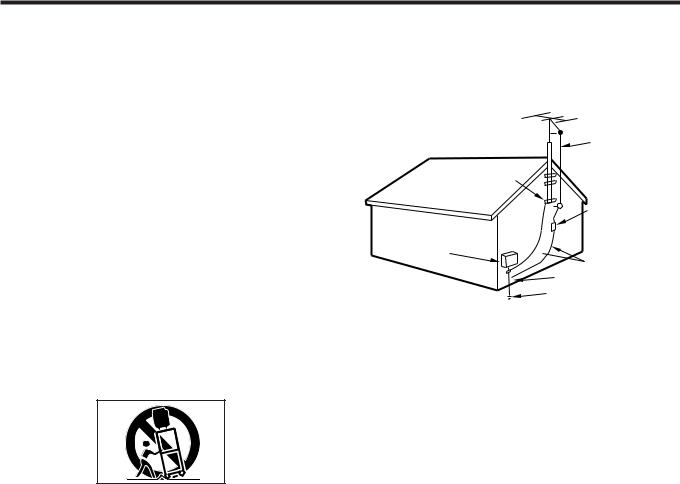
14)Outdoor Antenna Grounding - If an outside antenna or cable system is connected to the product, be sure the antenna or calbe system is grounded so as to provide some protection against voltage surges and built-up static charges. Article 810 of the National Electrical Code, ANSI/NFPA 70, provides information with regard to proper grounding of the mast and supporting structure, grounding of the lead-in wire to an antenna discharge unit, size of grounding conductors, location of antenna-discharge unit, connection to grounding electrodes, and requirements for the grounding electrode.
“Note to CATV system installer:
This reminder is provided to call the CATV system installer’s attention to Section 820-40 of the NEC which provides guidelines for proper grounding and, in particular, specifies that the cable ground shall be connected to the grounding system of them building, as close to the point of cable entry as practical.
Example of Antenna Grounding as per National Electrical Code, ANSI/NFPA 70
GROUND
CLAMP
ANTENNA
LEAD IN
WIRE
ANTENNA DISCHARGE UNIT (NEC SECTION 810-20)
ELECTRIC
SERVICE
EQUIPMENT  GROUNDING CONDUCTORS (NEC SECTION 810-21)

 GROUND CLAMPS
POWER SERVICE GROUNDING
ELECTRODE SYSTEM
(NEC ART 250,PART H)
NEC-NATIONAL ELECTRICAL CODE
15)Lightning-For added protection for this product during a lightning storm, or when it is left unattended and unused for long periods of time, unplug it from the wall outlet and disconnect the antenna or cable system. This will prevent damage to the product due to lightning and power-line surges.
16)Power Lines-An outside antenna system should not be located in the vicinity of overhead power lines or other electric light or power circuits, or where it can fall into such power lines or circuits. When installing an outside antenna system, extreme care should be taken to keep from touching such power lines or circuits as contact with them might be fatal.
17)Overloading - Do not overload wall outlets, extension cords, or integral convenience receptacles as this can result in a risk of fire or electric shock.
18)Object and Liquid Entry - Never push objects of any kind into this product through openings as they may touch dangerous voltage points or short-out parts that could result in a fire or electric shock. Never spill liquid of any kind on the product.
19)Servicing - Do not attempt to service this product yourself as opening or removing covers may expose you to dangerous voltage or other hazards. Refer all servicing to qualified service personnel.
20)Damage Requiring Service - Unplug this product from the wall outlet and refer servicing to qualified service personnel under the following conditions:
a) When the power-supply cord or plug is damaged.
b) If liquid has been spilled, or objects have fallen into the product.
c) If the product has been exposed to rain or water.
d) If the product does not operate normally by following the operating instructions. Adjust only those controls that are covered by the operating instructions as an improper adjustment of other controls may result in damage and will often require extensive work by a qualified technician to restore the product to its normal operation.
e) If the product has been dropped or damaged in any way.
f) when the product exhibits a distinct change in performance-this indicates a need for service.
21)Replacement Parts - When replacement parts are required, be sure the service technician has used replacement parts specified by the manufacturer or have the same characteristics as the original part. Unauthorized substitutions may result in fire, electric shock, or other hazards.
22)Safety Check - Upon completion of any service or repairs to this product, ask the service technician to perform safety checks to determine that the product is in proper operating condition.
23)Wall or Ceiling Mounting - The product should be mounted to a wall or ceiling only as recommended by the manufacturer.
24)Heat-The product should be situated away from heat sources such as radiators, heat registers, stoves, or other products
(including amplifiers) that produce heat.
- 2 -

CONTENTS
PRECAUTIONS . . . . . . . . . . . . . . . . . . . . . . . . . . . . . . . . . . . . . . . . . . . . . . . . . . . . . . . . . . . . . . . . . . . . . . . . . . . . . . . . . . . . . . . . 4 CONNECTIONS
Audio Connections . . . . . . . . . . . . . . . . . . . . . . . . . . . . . . . . . . . . . . . . . . . . . . . . . . . . . . . . . . . . . . . . . . . . . . . . . . . . . . . . . 5 Video Connections . . . . . . . . . . . . . . . . . . . . . . . . . . . . . . . . . . . . . . . . . . . . . . . . . . . . . . . . . . . . . . . . . . . . . . . . . . . . . . . . . 6 Connecting Antennas . . . . . . . . . . . . . . . . . . . . . . . . . . . . . . . . . . . . . . . . . . . . . . . . . . . . . . . . . . . . . . . . . . . . . . . . . . . . . . 8 Connecting Speaker Systems . . . . . . . . . . . . . . . . . . . . . . . . . . . . . . . . . . . . . . . . . . . . . . . . . . . . . . . . . . . . . . . . . . . . . . 9
CONTROLS AND INDICATORS . . . . . . . . . . . . . . . . . . . . . . . . . . . . . . . . . . . . . . . . . . . . . . . . . . . . . . . . . . . . . . . . . 10 ~ 11 AUDIO OPERATIONS
Sleep Timer Operation . . . . . . . . . . . . . . . . . . . . . . . . . . . . . . . . . . . . . . . . . . . . . . . . . . . . . . . . . . . . . . . . . . . . . . . . . . . . 12 Basic Operation . . . . . . . . . . . . . . . . . . . . . . . . . . . . . . . . . . . . . . . . . . . . . . . . . . . . . . . . . . . . . . . . . . . . . . . . . . . . . . . . . . . 12 Audio Adjustments . . . . . . . . . . . . . . . . . . . . . . . . . . . . . . . . . . . . . . . . . . . . . . . . . . . . . . . . . . . . . . . . . . . . . . . . . . . . . . . 13 Radio Reception . . . . . . . . . . . . . . . . . . . . . . . . . . . . . . . . . . . . . . . . . . . . . . . . . . . . . . . . . . . . . . . . . . . . . . . . . . . . . . . . . . . 14 Tuning . . . . . . . . . . . . . . . . . . . . . . . . . . . . . . . . . . . . . . . . . . . . . . . . . . . . . . . . . . . . . . . . . . . . . . . . . . . . . . . . . . . . . . . . . . . . 15 Listening to Records and Compact Discs . . . . . . . . . . . . . . . . . . . . . . . . . . . . . . . . . . . . . . . . . . . . . . . . . . . . . . . . . 16 Playing MD/TAPE 1 Deck . . . . . . . . . . . . . . . . . . . . . . . . . . . . . . . . . . . . . . . . . . . . . . . . . . . . . . . . . . . . . . . . . . . . . . . . . . 16 Playing TAPE 2 Deck . . . . . . . . . . . . . . . . . . . . . . . . . . . . . . . . . . . . . . . . . . . . . . . . . . . . . . . . . . . . . . . . . . . . . . . . . . . . . . 17 Recording a Source . . . . . . . . . . . . . . . . . . . . . . . . . . . . . . . . . . . . . . . . . . . . . . . . . . . . . . . . . . . . . . . . . . . . . . . . . . . . . . . 17 Dubbing from TAPE 2 to MD/TAPE 1 . . . . . . . . . . . . . . . . . . . . . . . . . . . . . . . . . . . . . . . . . . . . . . . . . . . . . . . . . . . . . 17
VIDEO OPERATIONS
Playing Video Sources . . . . . . . . . . . . . . . . . . . . . . . . . . . . . . . . . . . . . . . . . . . . . . . . . . . . . . . . . . . . . . . . . . . . . . . . . . . . 18 Recording with a Video Deck . . . . . . . . . . . . . . . . . . . . . . . . . . . . . . . . . . . . . . . . . . . . . . . . . . . . . . . . . . . . . . . . . . . . . 18
SURROUND EFFECTS
Surround Modes . . . . . . . . . . . . . . . . . . . . . . . . . . . . . . . . . . . . . . . . . . . . . . . . . . . . . . . . . . . . . . . . . . . . . . . . . . . . . . . . . . 19 Speaker Positioning . . . . . . . . . . . . . . . . . . . . . . . . . . . . . . . . . . . . . . . . . . . . . . . . . . . . . . . . . . . . . . . . . . . . . . . . . . . . . . . 20 Speaker Configuration . . . . . . . . . . . . . . . . . . . . . . . . . . . . . . . . . . . . . . . . . . . . . . . . . . . . . . . . . . . . . . . . . . . . . . . . . . . . 20 DELAY Time/Effect . . . . . . . . . . . . . . . . . . . . . . . . . . . . . . . . . . . . . . . . . . . . . . . . . . . . . . . . . . . . . . . . . . . . . . . . . . . . . . . . 21 Channel Level . . . . . . . . . . . . . . . . . . . . . . . . . . . . . . . . . . . . . . . . . . . . . . . . . . . . . . . . . . . . . . . . . . . . . . . . . . . . . . . . . . . . . 21 Playing Surround Sound . . . . . . . . . . . . . . . . . . . . . . . . . . . . . . . . . . . . . . . . . . . . . . . . . . . . . . . . . . . . . . . . . . . . . . . . . . 22
BACK-UP SYSTEM . . . . . . . . . . . . . . . . . . . . . . . . . . . . . . . . . . . . . . . . . . . . . . . . . . . . . . . . . . . . . . . . . . . . . . . . . . . . . . . . . . . 22
Back-up Memory Function . . . . . . . . . . . . . . . . . . . . . . . . . . . . . . . . . . . . . . . . . . . . . . . . . . . . . . . . . . . . . . . . . . . . . . . . 22 When to Use RESET Function . . . . . . . . . . . . . . . . . . . . . . . . . . . . . . . . . . . . . . . . . . . . . . . . . . . . . . . . . . . . . . . . . . . . . 22
OSD (ON SCREEN DISPLAY) . . . . . . . . . . . . . . . . . . . . . . . . . . . . . . . . . . . . . . . . . . . . . . . . . . . . . . . . . . . . . . . . . . . . . . . . . 23 REMOTE CONTROL UNIT . . . . . . . . . . . . . . . . . . . . . . . . . . . . . . . . . . . . . . . . . . . . . . . . . . . . . . . . . . . . . . . . . . . . . . . . . . . . 28
Using the Remote Control Unit . . . . . . . . . . . . . . . . . . . . . . . . . . . . . . . . . . . . . . . . . . . . . . . . . . . . . . . . . . . . . . . . . . . 28 Battery Installation . . . . . . . . . . . . . . . . . . . . . . . . . . . . . . . . . . . . . . . . . . . . . . . . . . . . . . . . . . . . . . . . . . . . . . . . . . . . . . . . 28
TROUBLESHOOTING . . . . . . . . . . . . . . . . . . . . . . . . . . . . . . . . . . . . . . . . . . . . . . . . . . . . . . . . . . . . . . . . . . . . . . . . . . . . . . . . 29 SPECIFICATIONS . . . . . . . . . . . . . . . . . . . . . . . . . . . . . . . . . . . . . . . . . . . . . . . . . . . . . . . . . . . . . . . . . . . . . . . . . . . . . . . . . . . . 30
- 3 -

PRECAUTIONS
Read This Before Operating
Choose the installation location of your unit carefully. Avoid placing it in direct sunlight or close to a source of heat. Also avoid locations subject to vibrations and excessive dust, heat, cold or moisture.
The ventilation holes should not be covered. Make sure there is at least 10 cm (4 inches) of space above and at least 10 cm (4 inches) of space beside the amplifier/receiver. Do not place a CD player or other equipment on top of the amplifier/receiver.
Do not open the cabinet as this might result in damage to the circuitry or electrical shock. If a foreign object should get into the set, contact your dealer.
When removing the power plug from the wall outlet, always pull directly on the plug, never yank the cord.
Do not attempt to clean the unit with chemical solvents as this might damage the finish. Use a clean, dry cloth. Keep this manual in a safe place for future refernce.
TO THE USER
This equipment has been tested and found to comply with the limits for a A/V receiver, pursuant to Part 15 of the FCC Rules. These limits are designed to provide reasonable protection against interference in a residential area. This device generates and uses radio frequency energy and if not installed and used in accordance with the instructions, it may cause interference to radio or TV reception. If this unit does cause interference with TV or radio reception you can try to correct the interference by one or more of the following measures :
a)Reorient or relocate the receiving antenna.
b)Increase the separation between the equipment and the receiver.
c)Plug the equipment into a different outlet so that it is not on the same circuit as the receiver.
If necessary, consult the dealer or an experienced radio/TV technician for additional suggestions.
CAUTION
Changes or modifications to this equipment not expressly approved by WELTON U.S.A. for compliance could void the user’s authority to operate this equipment.
The equipment draws nominal non-operating power from the AC outlet with its POWER switch in the STANDBY position.
For CANADA
AC POWER CORD CONNECTION CAUTION :
TO PREVENT ELECTRIC SHOCK, MATCH WIDE BLADE OF PLUG TO WIDE SLOT, FULLY INSERT.
Pour le CANADA
CORDON DE CONNEXION CA ATTENTION :
POUR ÉVITER LES CHOCS ÉLECTRIQUES, INTRODUIRE LA LAME LA PLUS LARGE DE LA FICHE DANS LA BORNE CORRESPONDANTE DE LA PRISE ET POUSSER JUSQU'AU FOND.
CAUTION Regarding Placement
To maintain proper ventilation, be sure to leave a space around the unit (from the largest outer dimensions including projections) equal to, or greated than, shown below :
Left and right Panels : 10cm
Rear Panel |
: 10cm |
Top Panel |
: 10cm |
- 4 -
CONNECTIONS
CAUTION :
Do not plug the power cord of any component into AC outlets and do not turn their POWER switches on until all connections have been performed.
The cable connectors should be fully inserted into the jacks. Loose connections may cause hum and noise.
Read the instructions for each component you intend to use with the receiver.
Refer to "Connecting Antennas" on pages 8~9.
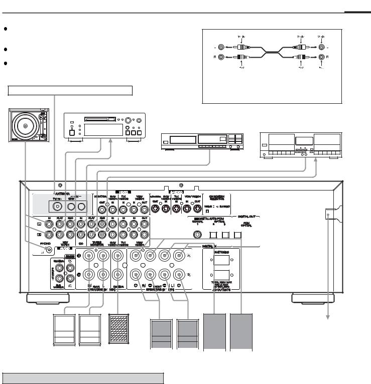
Audio connection cords
To make these connections, use interconnect cords with
RCA plugs. Make sure that you connect the white pinplug to the white jacks (left) and the red pin-plug to the red jacks (right).
Turntable |
MD Deck or Tape Deck
CD Player |
Tape Deck |
LINE OUT
LINE IN
LINE OUT
LINE OUT
LINE IN
To WALL outlet
Right |
Left |
Center |
|
|
|
|
|
|
|
|
|
|
|
|
|
|
|
|
|
|
|
|
|
|
|
|
|
|
|
|
|||
|
|
|
|
|
|
|
|
|
|
|
|
|
|
|||
Rear Speaker |
Speaker |
|
|
Right |
|
|
Left |
|
|
Left |
|
Right |
||||
|
|
|
Front B Speaker |
|
|
Front A Speaker |
||||||||||
|
|
|
|
|
|
|
||||||||||
Connecting Audio Equipment
AUDIO signal jacks PHONO jacks
Connect the turntable’s output jacks to the PHONO IN jacks.
CD IN jacks
Connect the CD player’s output (LINE OUT) jacks to the CD IN jacks.
MD/TAPE 1 (PLAY/REC) jacks
Connect the MD/TAPE 1 jacks to the MD player or the cassette
deck.
 Connect the MD player or cassette deck output (LINE OUT) jacks to the PLAY jacks.
 Connect the MD player or cassette deck input (LINE IN) jacks to the REC jacks.
TAPE 2 (PLAY/REC) jacks
 Connect the cassette deck output (LINE OUT) jacks to the PLAY (TAPE 2 MONITOR) jacks.
 Connect the cassette deck input (LINE IN) jacks to the REC (TAPE 2 MONITOR) jacks.
- 5 -
CONNECTIONS
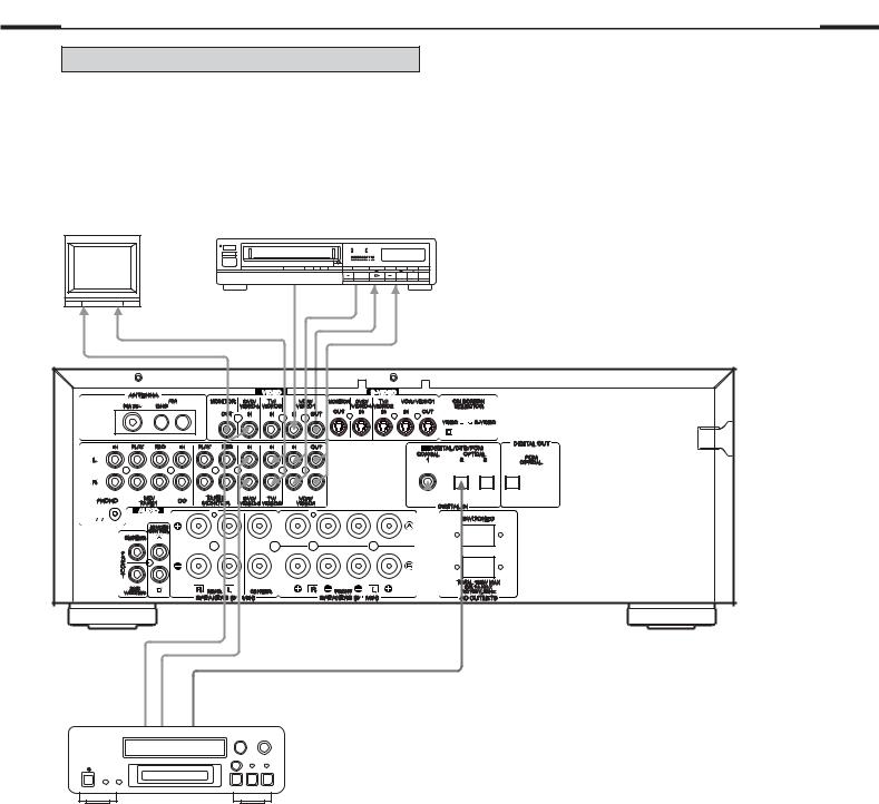
Connecting Video Equipment
AUDIO signal jacks
 Connect the video deck (VCR) LINE output (AUDIO OUT) jacks to the IN (VCR/VIDEO 1) jacks, and the video deck (VCR) LINE input (AUDIO IN) jacks to the OUT (VCR/VIDEO 1) jacks.
 Connect the TV AUDIO OUTPUT jacks to the VIDEO 2 IN jacks.
TV |
|
VCR/VIDEO 1 |
|
|
Video Deck (VCR) |
||
|
|
||
|
OUT |
AUDIO OUT |
|
AUDIO OUT |
VIDEO |
||
VIDEO IN |
|||
|
|
||
VIDEO IN |
|
AUDIO IN |
|
|
|
S-VIDEO signal jacks
 Connect the TV monitor S-VIDEO IN jack to the MONITOR OUT jack.
 Connect the video deck (VCR) S-VIDEO OUT jack to the S-VIDEO VCR IN jack. Connect the video deck (VCR) S-VIDEO IN jack to the S-VIDEO VCR OUT jack.
 Connect the TV or DVD player S-VIDEO OUTPUT jacks to the S-VIDEO TV/VIDEO 2 IN jack or S-VIDEO DVD/VIDEO 4 IN jack.
Notes :
 The FUNCTION (source) selector for the S-VIDEO inputs and VIDEO inputs work in conjunction with each other.
  This unit’s S-VIDEO (IN/OUT) jacks and VIDEO (IN/OUT) pin jacks have independent circiut structures, so that video signals input from the S-VIDEO jacks are only output from the S-VIDEO jack outputs and video signals input from the VIDEO pin jacks are only output from the VIDEO pin jack outputs.
VIDEO 4
DVD Player
VIDEO OUT |
AUDIO OUT |
DIGITAL OUT (OPTICAL) |
VIDEO signal jacks
 Connect the TV monitor VIDEO IN jack to the MONITOR OUT jack.
 Connect the video deck (VCR) VIDEO OUT (VIDEO) jack to the IN (VCR/VIDEO 1) jack.
Connect the video deck (VCR) VIDEO IN jacks to the
OUT (VCR/VIDEO 1) jack.
 Connect the DVD player or TV VIDEO OUTPUT jacks to the VIDEO 2 or VIDEO 4 IN jacks.
DIGITAL OUT (PCM OPTICAL) jack
 Connect the CD-R (or MD deck) DIGITAL IN iack to the DIGITAL OUT jack. (Use the optional optical fiber cable.)
DOLBY DIGITAL/DTS/PCM DIGITAL IN (1, 2, 3) jacks
 If the player is provided with a DIGITAL OUTPUT jack, connect it to the DIGITAL IN jack. (Use the optional coaxial cord or optical fiber cable.)
 When an optical fiber cable is used for connection, remove the caps protecting both ends of the optical cable and the connectors.
Notes :
 When both the analog AUDIO IN (VIDEO 2/4) and DIGITAL IN (1, 2, 3) of the receiver are connected, signals
input to the DIGITAL IN jack (1, 2, 3) have priority.
 For better sound quality, we recommend using digital rather than analog connections when connecting the DVD player or TV.
- 6 -
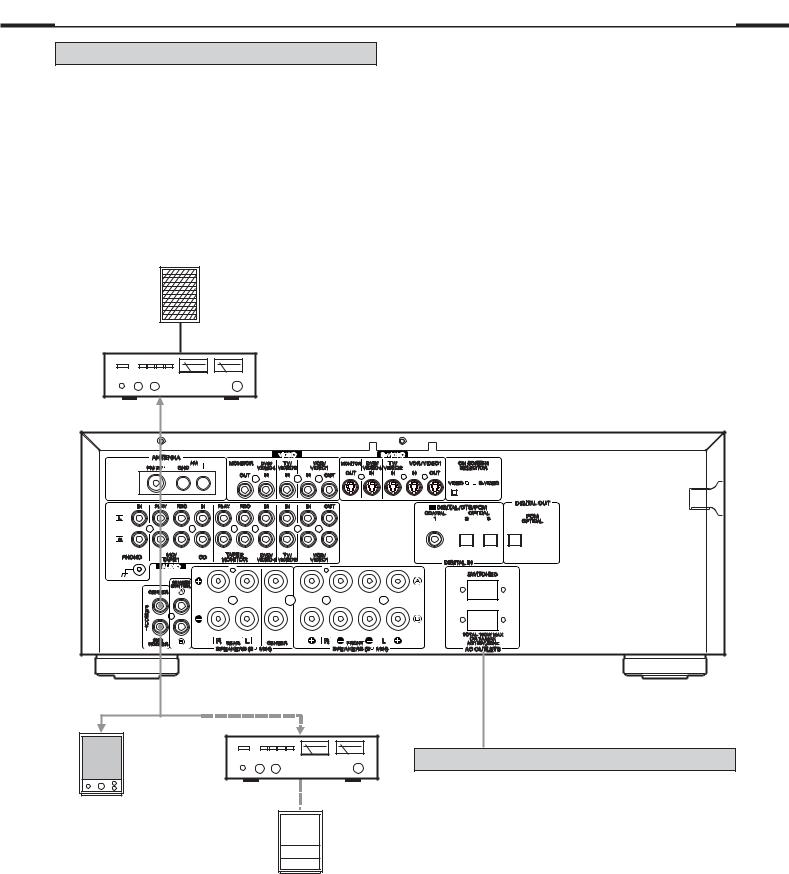
Connecting the PRE OUT jacks
This unit is equipped with Subwoofer and Center PREOUT jacks. These jacks allow connection off an optional powered subwoofer and connection of the center channel output to specially equipped TV’s that will play the center channel through the TV speakers.
Note :
 Subwoofer preout signals are not amplified. Therefore, when using the Subwoofer out jack, you must use a subwoofer with built-in amplifier.
Center Speaker
Notes :
 If a speaker is connected directly to the PRE OUT jack without an amplifier connected, no sound comes from the speaker.
 Subwoofer speakers are optional and are not required.
Power Amplifier
or |
Power Amplifier
Subwoofer with
Subwoofer without
AC OUTLETS
SWITCHED :
These outlets are only active when the receiver is turned on.
Caution :
 Make sure that the total power consumption of all equipment connected to the outlets on the receiver does not exceed 100 watts.
- 7 -
CONNECTIONS
VIDEO CONNECTIONS
VIDEO |
|
AUDIO L |
AUX/ |
AUDIO R |
VIDEO 3 INPUT |
AUDIO OUT
VIDEO OUT
Video Camera Recorder, etc.
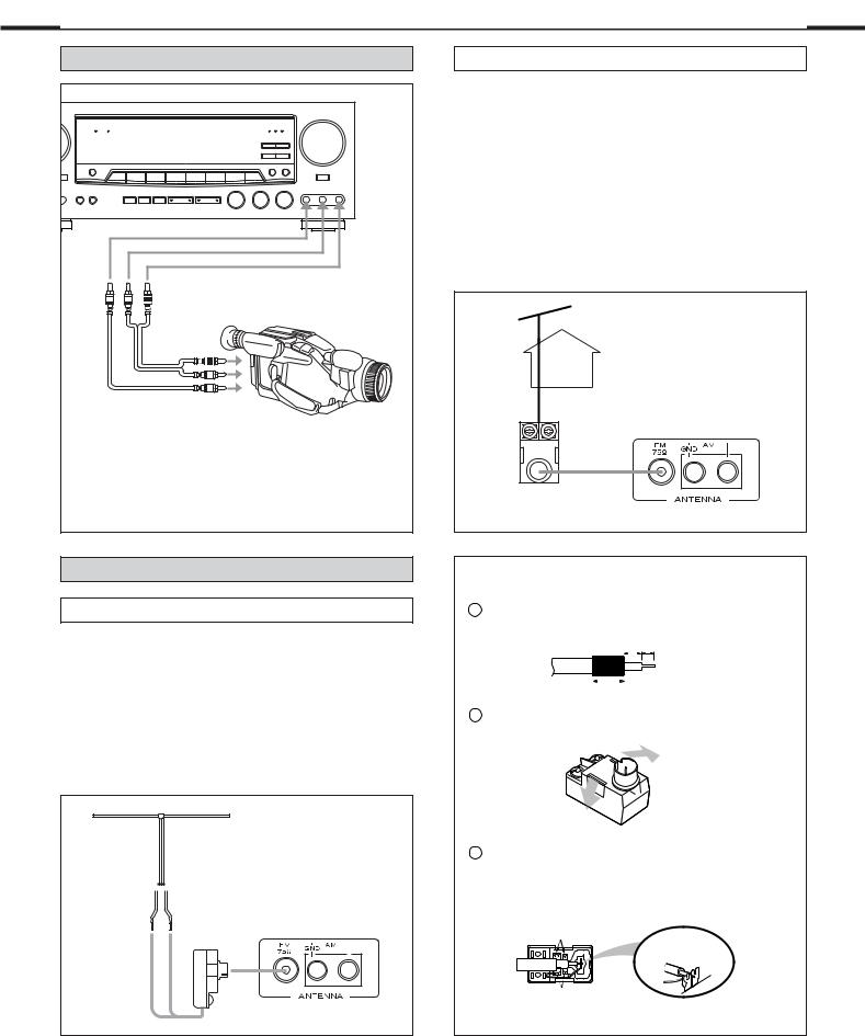
 Connect the video camera recorder AUDIO OUTPUT to the AUDIO (L)/(R) jacks and VIDEO OUT to the VIDEO jack of the AUX/ VIDEO 3 INPUT.
Connecting Antennas
FM Indoor Antenna
In an area with strong FM signals, the “T”-type FM antenna provided is sufficient.
Extend this into a “T” shape and connect the two wires at the base of the “T” to the provided matching transformer, as shown.
After completing connection, plug the transformer into the “FM 75 ” socket. Extend the top of the “T” and fix with thumb tracks, or the like, to a wall or window frame for the best possible reception.
“T”-type FM Antenna (300 ) (provided)
Matching Transforme
(provided)
FM Outdoor Antenna
In an area where FM signals are weak, it will be necessary to use a 75-ohm unbalanced-type outdoor FM antenna using the provided matching transformer, as shown. Generally, a 3-element antenna will be sufficient; if you live in an area where the FM signals are particularly weak, it may be necessary to use one with 5 or more elements.
Connect the coaxial cable of the antenna to the matching transformer as shown.
After completing connection, plug the transformer into the “FM 75 ” socket.
 Outdoor FM Antenna (75 )
Matching Transforme (provided)
How to connect a coaxial cable to the matching transformer
1 Strip the cable and dress it as shown.
4mm 3mm
7mm
2Press both side tabs outward to remove the cover.
3 Wrap the core conductor around the central metal fixture as shown. Crimp the jagged metal fixtures so they hold the braided portion using pliers, etc. Put the cover back in place.
Jagged metal
Insert into slit.
Jagged metal
- 8 -
AM Antenna
 AM Indoor Loop Antenna
A high-performance AM loop antenna provided with the receiver is sufficient for good reception in most areas. Connect the loop antenna’s wires to the AM antenna terminals as shown. Place the antenna on a shelf, for example, or hang it on a window frame, etc., in the direction which gives the best reception, as far away as possible from the system, speaker cords and the power cord, to prevent unwanted noise.
 AM Outdoor Antenna
If the AM loop antenna provided does not deliver sufficient reception (because you are too far from the transmitter or in a concrete building, etc.), it may be necessary to use an outdoor AM antenna. Use an insulated wire more than 15 ft (5 m) long, strip one end, and connect this to the terminal as shown.
For better reception, connect the GND terminal to a reliable ground.
Note : Even when using an outdoor AM antenna, do not disconnect the AM loop antenna.
AM Indoor Antenna (provided)
AM Outdoor
Antenna
- 9 -
Connecting Speaker Systems
Caution :
To avoid damaging the speakers by inputting a sudden high-level signal, be sure to switch the power off before connecting the speakers.
Connect the cable from each speaker to the
corresponding terminal on the rear of the receiver.
 Most speaker cables have different markings, textures or colors to help you tell the difference between negative and positive.
 Be sure to connect the positive (+) terminal on each speaker to the positive (+) terminal on the receiver. Similarly, connect the negative (-) terminal on the speaker to negative (-) terminal on the receiver.
Notes :
 Use speakers with a nominal impedance of 8 ohms or more.
 How to connect
(1)Strip back the cable covering by about 1 cm and twist the wire strands together.
(2)Turn the terminal cap counterclockwise to loosen it. The speaker terminal caps cannot be fully removed from the base.
(3)Insert the wire into the terminal fully and turn the terminal cap clockwise to securely connect it.
(4)Make sure it is fastened firm by pulling the cable lightly.

CONTROLS AND INDICATORS
 Front Panel
28 |
2 |
14 |
|
1 |
28 |
4 |
|
|
5 |
|
32 |
33 |
34 |
24 |
7 |
33 |
8 |
22 |
|
11 |
|
|
FUNCTION |
|
|
|
|
|
|
|
|
|
|
|
|
|
|
|
|
VOLUME |
|
|
|
|
|
|
|
|
|
|
|
|
|
|
|
|
|
DIGIT |
|
|
|
|
|
|
|
|
ANDBY |
MUTING |
|
|
|
|
|
|
|
|
|
COAXIAL OPTICAL |
|
|
|
||
|
|
|
|
|
|
|
|
|
|
|
|
|
|
|
BAND |
FM MODE |
|
|
|
|
|
|
|
|
|
|
|
|
|
|
|
|
|
|
|
MODE |
MEMOR |
|
|
|
|
|
|
|
SLEEP |
|
|
|
|
|
|
|
|
|
|
|
|
|
|
|
|
|
|
|
APE 2 |
|
|
|
|
|
|
|
|
|
|
|
|
|
|
|
|
BASS BOOST |
|
|
MUTING |
MONIT |
|
|
|
|
|
|
|
|
|
|
|
|
|
|
|
|
|
|
|
POWER |
|
|
|
|
|
|
|
|
|
|
BASS |
|
TREBLE |
|
BALANCE |
|
|
|
|
|
|
|
|
|
|
|
|
|
|
|
|
|
|
|
|
|
VIDEO |
AUDIO |
|
|
|
ANDBY/ON |
PHONES |
SPEAKERS |
|
|
TEST |
SPEAKER |
LEVEL |
ADJUST |
DELA |
TIME |
|
|
|
|
|
|
|
||
|
|
|
|
|
CONFIG |
SELECT |
|
CENTER |
REAR |
|
|
|
|
|
|
|
|
|
||
1 |
|
13 |
17 |
16 |
3 |
18 |
19 |
20 |
21 |
23 |
|
15 |
|
|
|
10 |
9 |
25 |
12 |
|
Example: |
Example: |
- 10 -
 Loading...