


DDR94
DDR 9
4
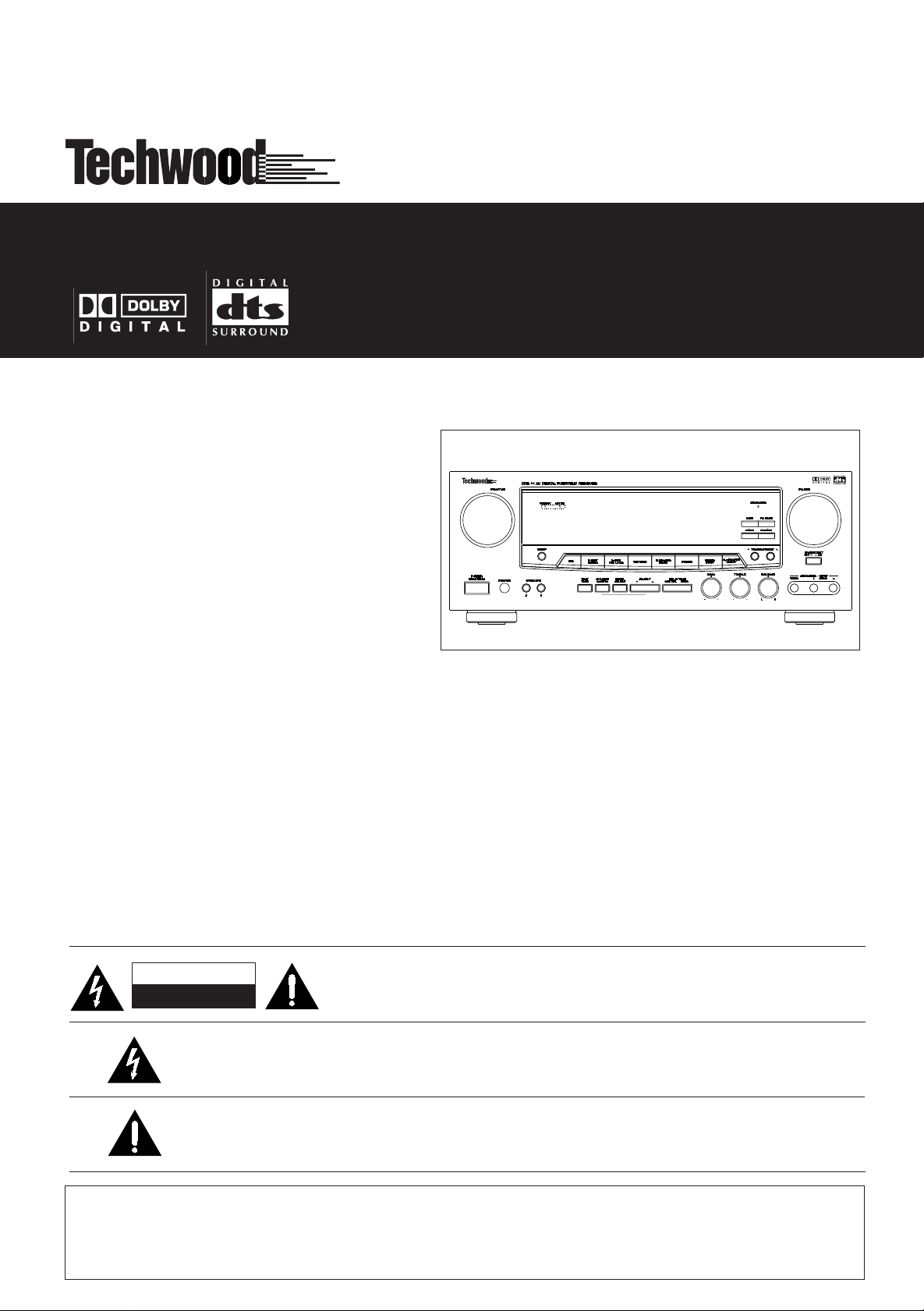
AV Digital Surround Receiver
OWNER’S MANUAL
CAUTION
RISK OF ELECTRIC SHOCK
DO NOT OPEN
The lightning flash with arrowhead symbol, within an equilateral triangle, is intended to alert the user to the
presence of uninsulated “dangerous voltage” within the product’s enclosure that may be of sufficient
magnitude to constitute a risk of electric shock to persons.
The exclamation point within an equilateral triangle is intended to alert the user to the presence of
important operating and maintenance (servicing) instructions in the literature accompanying the
appliance.
WARNING: TO PREVENT FIRE OR SHOCK HAZARD, DO NOT EXPOSE
THIS APPLIANCE TO RAIN OR MOISTURE.
CAUTION: TO REDUCE THE RISK OF ELECTRIC SHOCK, DO NOT REMOVE COVER (OR
BACK). NO USER-SERVICEABLE PARTS INSIDE. REFER SERVICING TO QUALIFIED
SERVICE PERSONNEL.
IMPORTANT SAFETY INSTRUCTIONS
CAUTION:
< Read all of these Instructions.
< Save these Instructions for later use.
< Follow all Warnings and Instructions marked on the audio
equipment.
1) Read Instructions — All the safety and operating instructions
should be read before the product is operated.
2) Retain Instructions — The safety and operating instructions
should be retained for future reference.
3) Heed Warnings — All warnings on the product and in the
operating instructions should be adhered to.
4) Follow Instructions — All operating and use instructions
should be followed.
5) Cleaning — Unplug this product from the wall outlet before
cleaning. Do not use liquid cleaners or aerosol cleaners. Use a
damp cloth for cleaning.
6) Attachments — Do not use attachments not recommended by
the product manufacturer as they may cause hazards.
7) Water and Moisture — Do not use this product near water_for
example, near a bath tub, wash bowl, kitchen sink, or laundry tub; in
a wet basement; or near a swimming pool; and the like.
8) Accessories — Do not place this product on an unstable cart,
stand, tripod, bracket, or table. The product may fall, causing
serious injury to a child or adult, and serious damage to the product.
Use only with a cart, stand, tripod, bracket, or table recommended
by the manufacturer, or sold with the product. Any mounting of the
product should follow the manufacturer’s instructions, and should
use a mounting accessory recommended by the manufacturer.
9) A product and cart combination should be moved with care.
Quick stops, excessive force, and uneven surfaces may cause the
product and cart combination to overturn.
10) Ventilation — Slots and openings in the cabinet are provided
for ventilation and to ensure reliable operation of the product and to
protect it from overheating, and these openings must not be
blocked or covered. The openings should never be blocked by
placing the product on a bed, sofa, rug, or other similar surface.
This product should not be placed in a built-in installation such as a
bookcase or rack unless proper ventilation is provided or the
manufacturer’s instructions have been adhered to.
11) Power Sources — This product should be operated only from
the type of power source indicated on the marking label. If you are
not sure of the type of power supply to your home, consult your
product dealer or local power company. For products intended to
operate from battery power, or other sources, refer to the operating
instructions.
12) Grounding or Polarization — This product may be equipped
with a polarized alternating-current line plug (a plug having one
blade wider than the other). This plug will fit into the power outlet
only one way. This is a safety feature. If you are unable to insert the
plug fully into the outlet, try reversing the plug. If the plug should
still fail to fit, contact your electrician to replace your obsolete outlet.
Do not defeat the safety purpose of the polarized plug.
13) Power-Cord Protection — Power-supply cords should be
routed so that they are not likely to be walked on or pinched by
items placed upon or against them, paying particular attention to
cords at plugs, convenience receptacles, and the point where they
exit from the product.
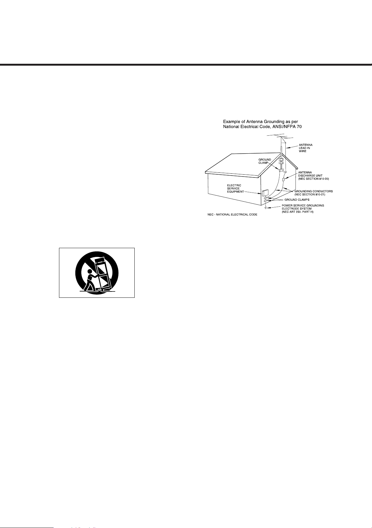
14) Outdoor Antenna Grounding — If an outside antenna or
cable system is connected to the product, be sure the antenna or
cable system is grounded so as to provide some protection against
voltage surges and built-up static charges. Article 810 of the
National Electrical Code, ANSI/NFPA 70, provides information with
regard to proper grounding of the mast and supporting structure,
grounding of the lead-in wire to an antenna discharge unit, size of
grounding conductors, location of antenna-discharge unit,
connection to grounding electrodes, and requirements for the
grounding electrode.
"Note to CATV system installer:
This reminder is provided to call the CATV system installer’s
attention to Section 820-40 of the NEC which provides guidelines
for proper grounding and, in particular, specifies that the cable
ground shall be connected to the grounding system of the building,
as close to the point of cable entry as practical."
15) Lightning — For added protection for this product during a
lightning storm, or when it is left unattended and unused for long
periods of time, unplug it from the wall outlet and disconnect the
antenna or cable system. This will prevent damage to the product
due to lightning and power-line surges.
16) Power Lines — An outside antenna system should not be
located in the vicinity of overhead power lines or other electric light
or power circuits, or where it can fall into such power lines or
circuits. When installing an outside antenna system, extreme care
should be taken to keep from touching such power lines or circuits
as contact with them might be fatal.
17) Overloading — Do not overload wall outlets, extension cords,
or integral convenience receptacles as this can result in risk of fire
or electric shock.
18) Object and Liquid Entry — Never push objects of any kind
into this product through openings as they may touch dangerous
voltage points or short-out parts that could result in a fire or electric
shock. Never spill liquid of any kind on the product.
19) Servicing — Do not attempt to service this product yourself as
opening or removing covers may expose you to dangerous voltage
or other hazards. Refer all servicing to qualified service personnel.
20) Damage Requiring Service — Unplug this product from the
wall outlet and refer servicing to qualified service personnel under
the following conditions:
a) when the power-supply cord or plug is damaged.
b) if liquid has been spilled, or objects have fallen into the product.
c) if the product has been exposed to rain or water.
d) if the product does not operate normally by following the
operating instructions. Adjust only those controls that are covered
by the operating instructions as an improper adjustment of other
controls may result in damage and will often require extensive work
by a qualified technician to restore the product to its normal
operation.
e) if the product has been dropped or damaged in any way.
f)when the product exhibits a distinct change in performance
this indicates a need for service.
21) Replacement Parts — When replacement parts are required,
be sure the service technician has used replacement parts specified
by the manufacturer or have the same characteristics as the original
part. Unauthorized substitutions may result in fire, electric shock, or
other hazards.
22) Safety Check — Upon completion of any service or repairs to
this product, ask the service technician to perform safety checks to
determine that the product is in proper operating condition.
23) Wall or Ceiling Mounting — The product should be mounted
to a wall or ceiling only as recommended by the manufacturer.
24) Heat — The product should be situated away from heat sources
such as radiators, heat registers, stoves, or other products
(including amplifiers) that produce heat.
_
2
2

Contents
TO THE USER
This equipment has been tested and
found to comply with the limits for a
Class B digital device, pursuant to Part
15 of the FCC Rules. These limits are
designed to provide reasonable
protection against interference in a
residential area. This device generates
and uses radio frequency energy and if
not installed and used in accordance
with the instructions, it may cause
interference to radio or TV reception.
If this unit does cause interference
with TV or radio reception you can try
to correct the interference by one or
more of the following measures:
a) Reorient or relocate the receiving
antenna.
b) Increase the separation between
the equipment and the receiver.
c) Plug the equipment into a different
outlet so that it is not on the same
circuit as the receiver.
If necessary, consult the dealer or an
experienced radio/TV technician for
additional suggestions.
Before Use......................................................................................................................4
Connection .....................................................................................................................5
Remote Control Unit....................................................................................................10
Basic Operations.........................................................................................................11
Radio Reception ..........................................................................................................13
Video Operations.........................................................................................................16
Playing Video Sources.........................................................................................16
Tape Dubbing.........................................................................................................16
S.A.V.E System Function......................................................................................16
Available Surround Modes........................................................................................17
Speaker Configuration................................................................................................20
Delay Time....................................................................................................................21
Test Tone......................................................................................................................22
Troubleshooting...........................................................................................................23
Specifications..............................................................................................................24
CAUTION
Changes or modifications to this
equipment not expressly approved by
WELTON U.S.A for compliance could
void the user's authority to operate this
equipment.
The equipment draws nominal
nonoperating power from the AC outlet
with its POWER switch in the STANDBY
position.
For CANADA
AC POWER CORD CONNECTION
CAUTION:
TO PREVENT ELECTRIC SHOCK, MATCH
WIDE BLADE OF PLUG TO WIDE SLOT,
FULLY INSERT.
3
Before Use
Read this before operation Before Connection
Read this before operation
< Choose the installation location of your unit carefully.
Avoid placing it in direct sunlight or close to a source of
heat. Also avoid locations subject to vibrations and
excessive dust, heat, cold or moisture.
< The ventilation holes should not be covered. Make sure
there is enough space above and beside the
amplifier/receiver (about 4 inches). Do not place a CD
player or other equipment on top of the amplifier/receiver.
< Donot open the cabinet as this might result in damage to
the circuitry or electrical shock. If a foreign object should
get into the set, contact your dealer.
< When removing the power plug from the wall outlet,
always pull directly on the plug, never yank the cord.
< Do not attempt to clean the unit with chemical solvents
as this might damage the finish. Use a clean, dry cloth.
< Keep this manual in a safe place for future reference.
Back-up Memory Function
This is the function which preserves the preset memory and
most-recent memory functions. In the event of a power
failure, or if the power cord of this unit is disconnected from
the electric outlet, the back-up memory will preserve the
preset memory and most-recent memory functions for as
long as approximately 3 days.
If the power supply is interrupted for 3 days or longer, the
memory settings will be erased.
When to Use RESET Switch
< When this system is subjected to an electrical shock.
< When the power is irregular.
In these cases, try the following (in power on VCR/VIDEO
1 function.):
CAUTION
Turn off the power of all the equipment before making
connections.
Read instructions of each component you intend to use
with this unit.
< Be sure to insert each plug securely. To prevent hum
and noise, do not bundle the connection cords with the
power cord or speaker cord.
Speaker Connections
Caution:
To avoid damaging the speakers with a sudden high-level
signal, be sure to switch the power off before connecting
the speakers.
< Check the impedance of your speakers.
Connect speaker with an impedance of 8 ohms or more.
The amplifier's red speaker terminals are the +
(positive) terminals and the black terminals are the _
(negative) terminals.
< The + side of the speaker cable is marked to make it
distinguishable from the _ side of the cable. Connect
this marked side to the red + terminal and the unmarked
side to the black terminal.
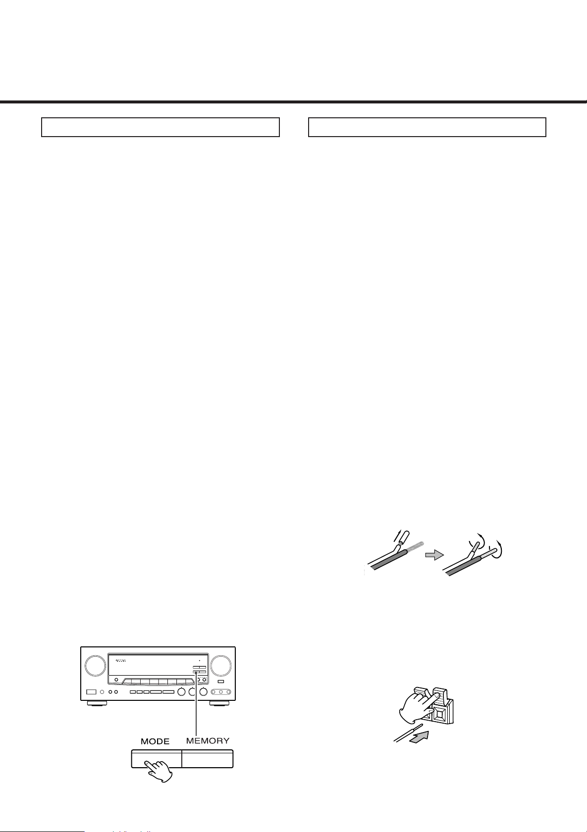
< Prepare the speaker cords for connection by stripping
off approximately 10 mm or less (no more as this could
cause a short-circuit) of the outer insulation.
Twist the wires tightly together so that they are not
straggly :
Press the TUNING MODE button for more than 3 seconds.
Note:
If the TUNING MODE button is pressed for more than 3
seconds in VCR/VIDEO 1 function or Standby mode, all
the memory will be erased.
How to connect
Press the lever, insert the stripped and twisted end
(approx. 3/8") of the cord, then release the lever :
Make sure it is fastened securely by pulling the cord
lightly.
4
Connection
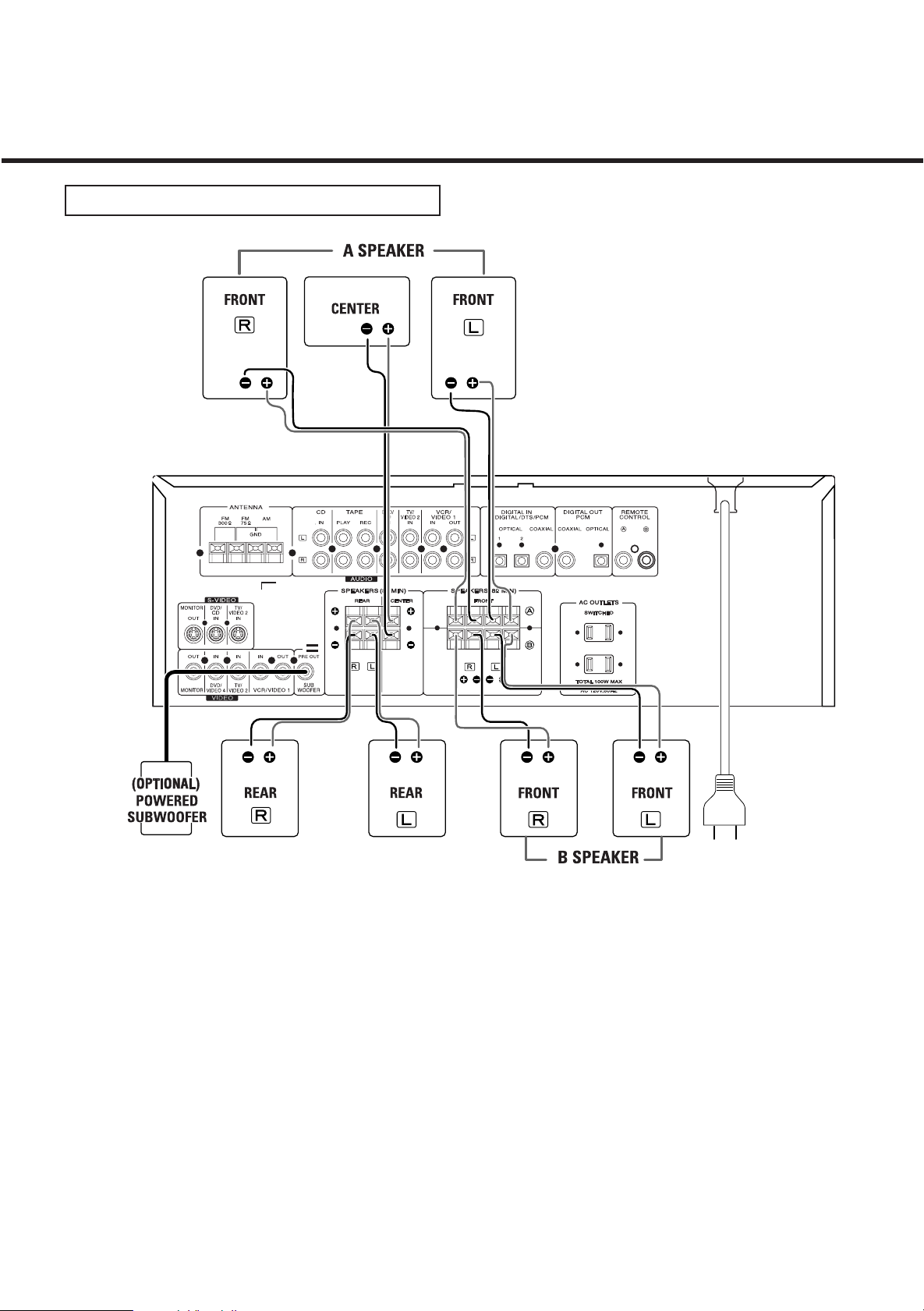
SPEAKERS, PRE OUT, AC OUTLETS
Power cord (AC)
Be sure to connect the power cord to an AC outlet
which supplies the correct voltage.
Hold the power plug when plugging or unplugging the
power cord.
PRE OUT ( SUB WOOFER ) jack
Use this jack to connect a powered sub-woofer or
passive sub-woofer with a power amplifier (OPTIONAL) .
AC OUTLETS (SWITCHED)
These outlets are only active when the receiver is
turned on.
Caution:
Make sure that the total power consumption of all
equipment connected to the outlets on the receiver does
not exceed 100 watts.
5
Connection
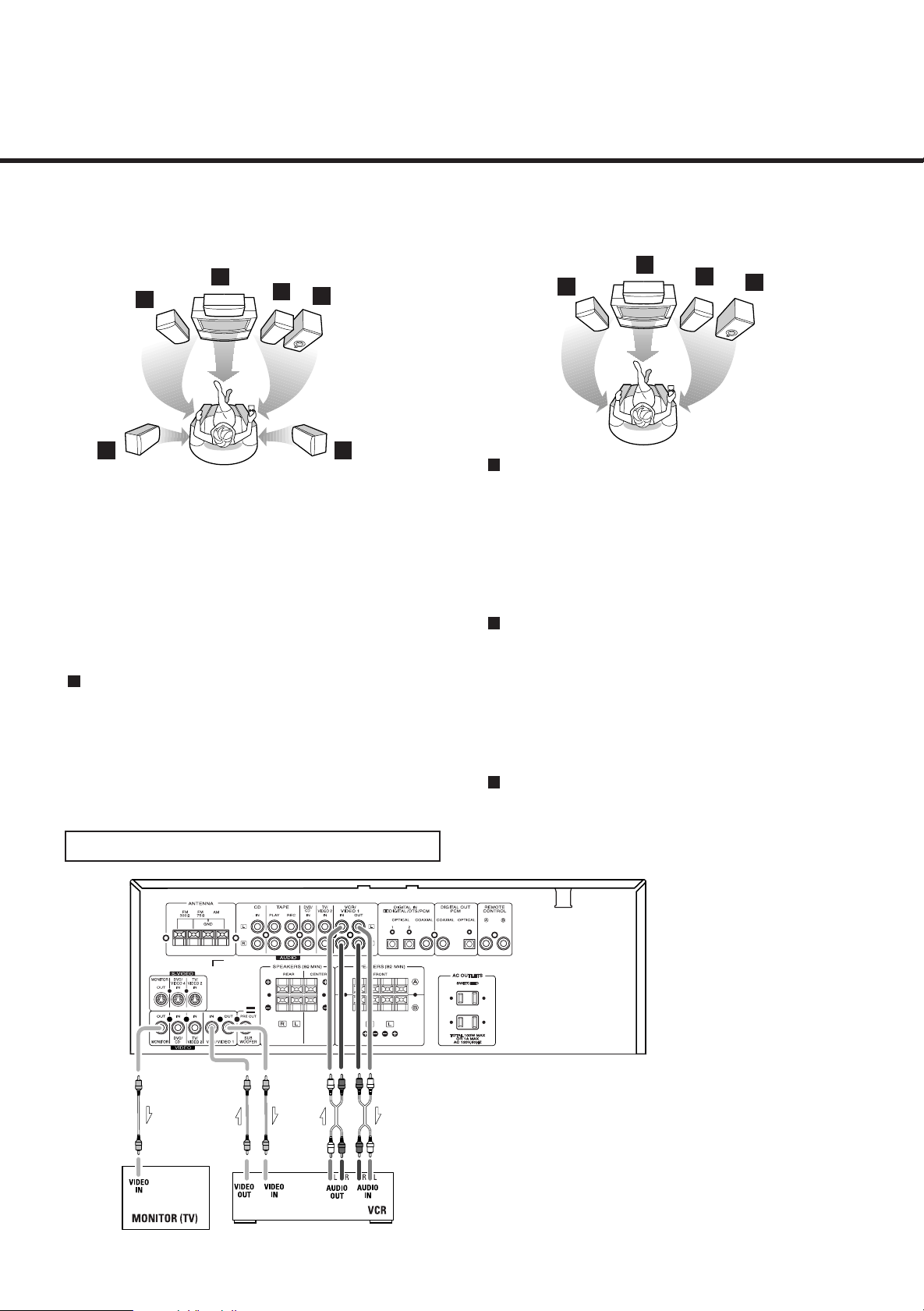
Speaker layout example when using SURROUND MODE or 3 STEREO
SURROUND
B
A
C
Positioning of the Speakers
The positioning of speakers differs according to the size
and acoustics of the listening room. While actually
listening to a program source, try various speaker
positions to determine which layout provides the best
surround effect.
Place the speakers connected to "L" to your left, and "R"
to your right.
A
Front speakers
Use magnetic shielded speakers, if you are using it near
your TV.
Place the front speakers in front of the listening position,
to the left and right of a TV.
Front speakers are required for all surround modes.
A
(OPTIONAL)
D
C
VCR
3 STEREO
B
A
B
Center speaker
Use magnetic shielded speaker, if you are using it near
your TV.
Place a center speaker between the front speakers, on
or below the TV.
This speaker improves sonic imaging and depth of field.
Be sure to connect a center speaker when using the 3
STEREO mode.
C
Rear speakers
Install these speakers above the level of the listener's
ears, to the left and right.
Do not install the rear speakers too far behind the
listening position. It might be effective to direct the rear
speakers towards a wall or ceiling to further disperse
the sound.
D
Subwoofer (Optional)
Reproduces powerful and deep bass sounds.
Use a subwoofer with built-in amplifier.
A Subwoofer is not required but may be added as an
option
A
(OPTIONAL)
D
Connect the component with RCA to RCA cords. Make
sure to connect :
white plug to white jack(L:left)
red plug to red jack(R:right)
yellow plug to yellow jack(VIDEO)
6
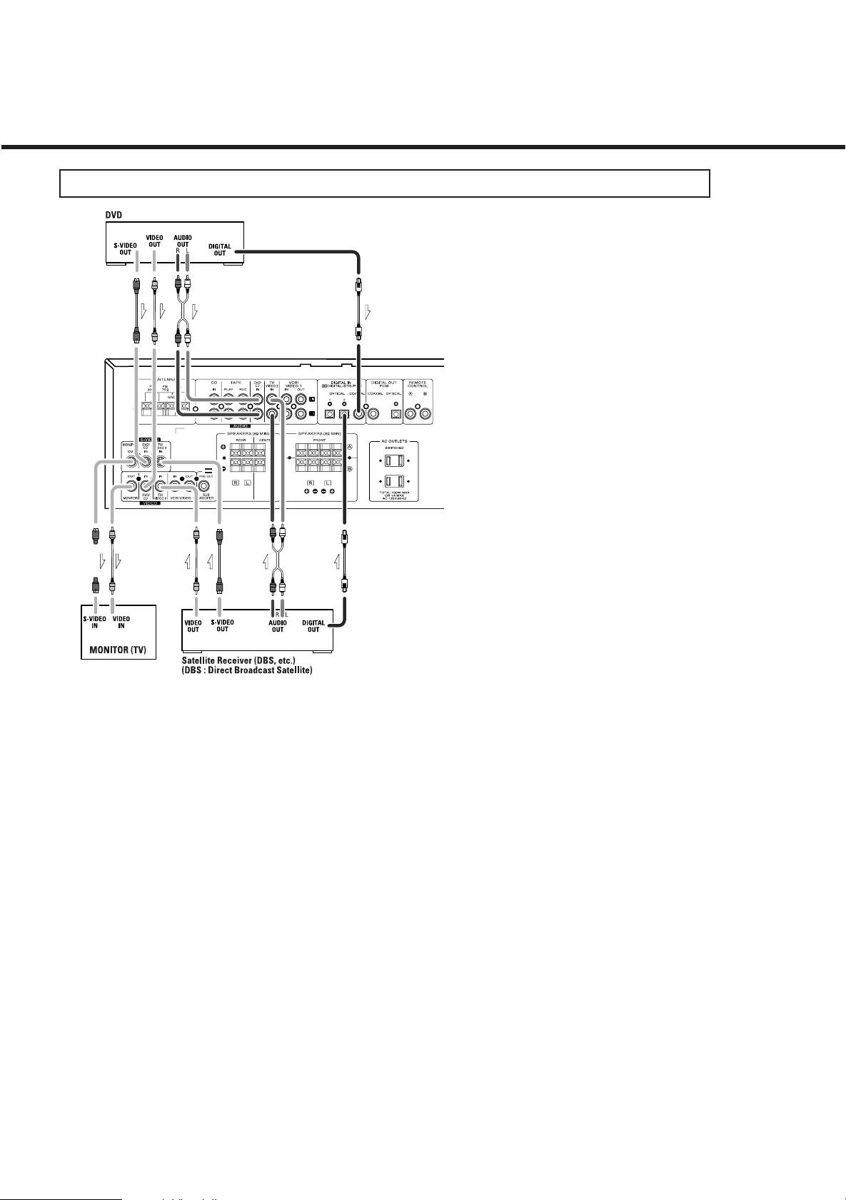
Connection
DVD PLAYER, CABLE BOX, SATELLITE RECEIVER (DSS), TELEVISION (MONITOR)
If you use both S-Video and RCA composite cables to
connect different video components to the DDR94, you must
also use both S-Video and RCA composite cables to
connect the TV monitor to the DDR94.
For example, if you connect a DVD player to the DDR94
using S-Video cable and a VCR using an RCA to RCA
composite cable, you must also connect the TV to the
DDR94 using both types of cables. This requires an S-Video
cable from the S-Video monitor out jack on the DDR94 to an
S-Video input on the TV (ie. Video 1). In addition, you must
use an RCA composite cable from the composite video
monitor out jack on the DDR94 to an RCA composite video
input on the TV but not the same input used for the S-Video
cable(ie: Video 2). Using this type of dual cable video
connection. you will need to switch the TV video input
source from TV to Video 1 to Video 2 depending on the video
source being played-TV, DVD or VCR.
Audio connections:
Some video components are equipped with special
digital audio outputs (ie: DVD players). If your video
component is equipped with a digital audio output, it is
recommended that you connect to the DDR94 using a
digital cable. Digital audio cables are required to use the
DTS and Dolby Digital surround sound modes. If you do
not use digital connections, the DDR94 will only operate
in Dolby Pro Logic, Dolby 3 Stereo, Theater, Hall, Stadium
When connecting video components such as DVD
players, cable boxes, satellite receivers and televisions,
you can use different types of cables depending on how
the video component is equipped.
Video connections:
If the video component is equipped with S-VIDEO jacks,
it is recommended that it be connected to the DDR94 or
directly to the television monitor using an S-VIDEO
cable. S-Video cables provide better picture clarity and
resolution. If the video component is not equipped with
an S-VIDEO jack, use a conventional RCA to RCA
composite cable to connect to the DDR94 or directly to
the television.
and Disco surround modes.
There are two types of digital cables - coaxial (75 ohm) and
optical. The DDR94 is equipped with both types of digital
inputs. These inputs are labeled DIGITAL/DTS/PCM on the
rearof the unit. Connect the video component outputs toany
one of the three digital inputs on the DDR94.
If the video component isnot equipped with a digital output,
use a dual RCA to RCA composite audio cable to connect to
the DDR94. Make sure to connect:
White plug to white jack ( L : left )
Red plug to red jack ( R : right )
The above illustration shows how to connect video
components to the DDR94.
Note:
When connection more than one video component to the
DDR94 (ie: VCR and DVD player) it is easier to use either
all S-Video cables or all RCA to RCA composite cables.
This allows both video signals (DVD and VCR) to be sent
through the DDR94 to the TV monitor using just one video
input on the TV (S-Video or RCA). Regardless of the
video component being played DVD or VCR, the picture
will always appear on the same video input of the
monitor.
Note:
When an optical cable is used, remove the protection
caps from the component and DDR94 before attempting
to insert the optical cable. If not using an optical cable or
if the cable is removed, always re-install the protection
caps to prevent dirt and dust from entering the inputs. If
using a coaxial digital cable, leave the protection caps in
both the video component and DDR94.
7
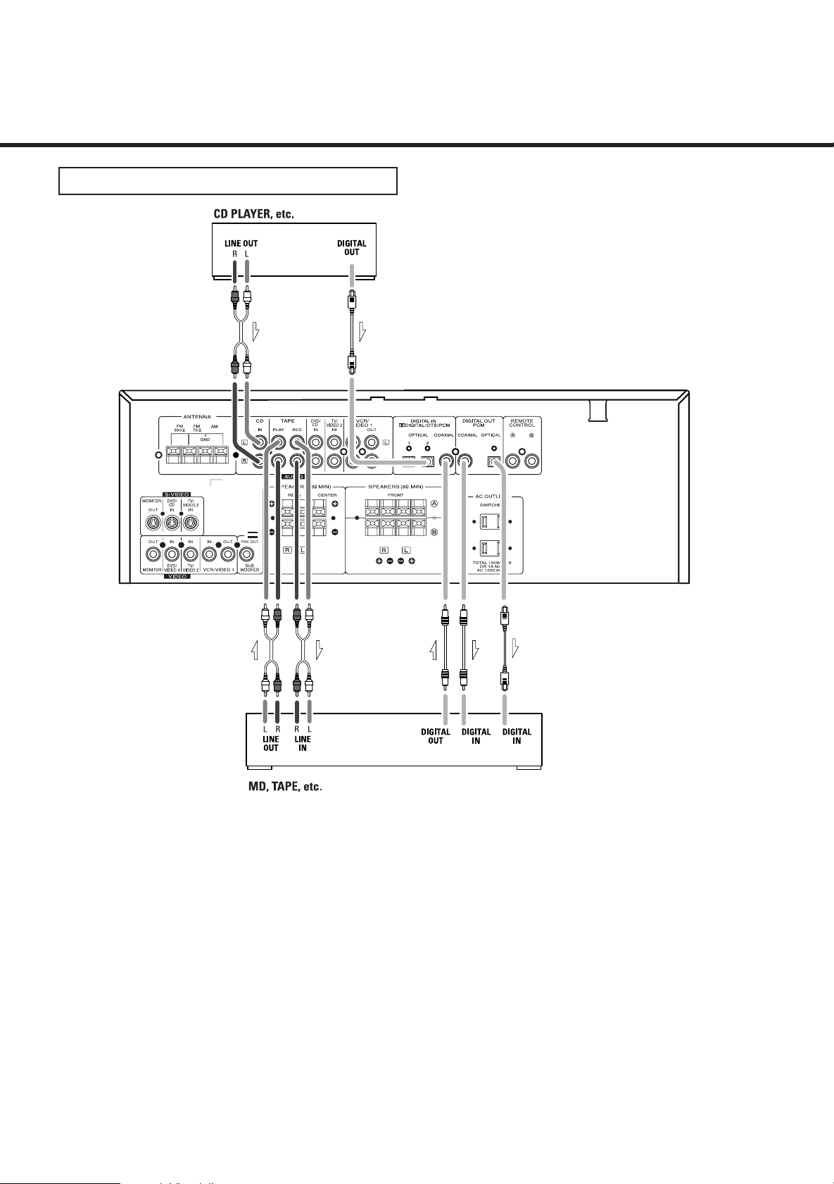
Connection
CD, TAPE Jacks
Connect the component with RCA to RCA cords. Make sure
to connect :
white plug to white jack(L:left)
red plug to red jack(R:right)
DIGITAL IN/OUT terminalsCD, TAPE jacks
If the CD player or tape player has digital outputs,
connect the component with coaxial cables or optical
cables.
DIGITAL IN to DIGITAL OUT(CD, etc.)
DIGITAL OUT to DIGITAL IN( MD, etc.)
< Connect to any one of the DIGITAL IN terminals.
< When using DIGITAL OPTICAL IN terminals, remove the
caps from the terminals. When you do not use them,
leave the caps in place.
< To record digitally, connect the source(CD player, etc.)
to DIGITAL IN and the recorder(MD, etc.) to DIGITAL
OUT.
8
 Loading...