

Page 1
E
ION
G
PHONES
ERS
ADJUST
LE
R
R
L
OFF
R
/ON
OR
BOOST
SPEAKER
G
LEVEL
SELECT
NCE
DE
MODE
COAXIAL
OPTICAL
G
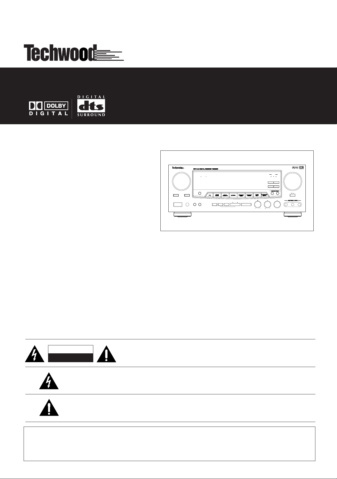
DDR 9
5
AV Digital Surround Receiver
FUNCTION
TAPE 2
MONITOR
MUTING
POWER
STANDBY/ON
PHONES
MUTING
STANDBY
SLEEP
DELAYTIME
ADJUST
LEVEL
TEST
SPEAKERS
A
B
SPEAKER
SELECT
TONE
CONFIG
REAR
CENTER
COAXIAL
BAND FM MODE
MODE
TREBLE
BASS
1223
VOLUME
DIGITAL
OPTICAL
MEMORY
BASS BOOST
OFF
ON
BALANCE
VIDEO
AUDIO L
R
R
L
OWNER’S MANUAL
CAUTION
RISK OF ELECTRIC SHOCK
DO NOT OPEN
CAUTION: TO REDUCE THE RISK OF ELECTRIC SHOCK, DO NOT REMOVE COVER (OR
BACK). NO USER-SERVICEABLE PARTS INSIDE. REFER SERVICING TO QUALIFIED
SERVICE PERSONNEL.
The lightning flash with arrowhead symbol, within an equilateral triangle, is intended to alert the user to the
presence of uninsulated “dangerous voltage” within the product’s enclosure that may be of sufficient
magnitude to constitute a risk of electric shock to persons.
The exclamation point within an equilateral triangle is intended to alert the user to the presence of
important operating and maintenance (servicing) instructions in the literature accompanying the
appliance.
THIS APPLIANCE TO RAIN OR MOISTURE.
WARNING: TO PREVENT FIRE OR SHOCK HAZARD, DO NOT EXPOSE
Page 2
IMPORTANT SAFETY INSTRUCTIONS
CAUTION:
Read all of these instructions.
•
• Save these instructions for later use.
• Follow all warnings and instructions marked on the audio
equipment.
1) Read instructions - All the safety and operating instructions
should be read before the product is operated.
2) Retain instructions - The safety and operating instructions
should be retained for future reference.
3) Heed Warnings - All warnings on the product and in the
operating instructions should be adhered to.
4) Follow Instructions - All operating and use instructions should
be followed.
5) Cleaning - Unplug this product from the wall outlet before
cleaning. Do not use liquid cleaners or aerosol cleaners. Use a
damp cloth for cleaning.
6) Attachments - Do not use attachments not recommended by
the product manufacturer as they may cause hazards.
7) Water and Moisture - Do not use this product near water-for
example, near a bath tub,wash bowl, kitchen sink, or laundry tub;
in a wet basement; or near a swimming pool; and the like.
8) Accessories - Do not place this product on an unstable cart,
stand, tripod, bracket, or table. The product may fall, causing
serious injury to a child or adult, and serious damage to the
product. Use only with a cart, stand, tripod, bracket, or table
recommended by the manufacturer, or sold with the product. Any
mounting of the product should follow the manufacturer’s
instructions, and should use a mounting accessory
recommended by the manufacturer.
9) A product and cart combination should be moved with care.
Quick stops, excessive force, and uneven surfaces may cause the
product and cart combination to overturn.
10) Ventilation - Slots and openings in the cabinet are provided
for ventilation and to ensure reliable operation of the product and
to protect it from overheating, and these openings must not be
blocked or covered. The openings should never be blocked by
placing the product on a bed, sofa, rug, or other similar surface.
This product should not be placed in a built-in installation such as
a bookcase or rack unless proper ventilation is provided or the
manufacturer’s instructions have been adhered to.
11) Power Sources - This product should be operated only from
the type of power source indicated on the marking label. If you
are not sure of the type of power supply to your home, consult
your product dealer or local power company. For products
intended to operate from battery power, or other sources, refer to
the operating instructions.
12) Grounding or Polarization - This product may be equipped
with a polarized alternating-current line plug (a plug having one
blade wider than the other). This plug will fit into the power outlet
only one way. This is a safety feature. If you are unable to insert
the plug fully into the outlet, try reversing the plug. If the plug
should still fail to fit, contact your electrician to replace your
obsolete outlet. Do not defeat the safety purpose of the polarized
plug.
13) Power-Cord Protection - Power-supply cords should be
routed so that they are not likely to be walked on or pinched by
items placed upon or against them, paying particular attention to
cords at plugs, convenience receptacles, and the point where they
exit from the product.
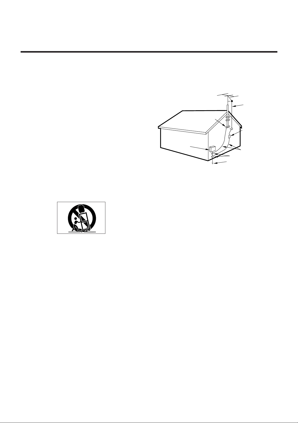
14) Outdoor Antenna Grounding - If an outside antenna or cable
system is connected to the product, be sure the antenna or calbe
system is grounded so as to provide some protection against
voltage surges and built-up static charges. Article 810 of the
National Electrical Code, ANSI/NFPA 70, provides information
with regard to proper grounding of the mast and supporting
structure, grounding of the lead-in wire to an antenna discharge
unit, size of grounding conductors, location of antenna-discharge
unit, connection to grounding electrodes, and requirements for
the grounding electrode.
“Note to CATV system installer:
This reminder is provided to call the CATV system installer’s
attention to Section 820-40 of the NEC which provides guidelines
for proper grounding and, in particular, specifies that the cable
ground shall be connected to the grounding system of them
building, as close to the point of cable entry as practical.
Example of Antenna Grounding as per
National Electrical Code, ANSI/NFPA 70
GROUND
CLAMP
ELECTRIC
SERVICE
EQUIPMENT
NEC-NATIONAL ELECTRICAL CODE
POWER SERVICE GROUNDING
ELECTRODE SYSTEM
(NEC ART 250,PART H)
ANTENNA
LEAD IN
WIRE
ANTENNA
DISCHARGE UNIT
(NEC SECTION 810-20)
GROUNDING CONDUCTORS
(NEC SECTION 810-21)
GROUND CLAMPS
15) Lightning-For added protection for this product during a
lightning storm, or when it is left unattended and unused for long
periods of time, unplug it from the wall outlet and disconnect the
antenna or cable system. This will prevent damage to the product
due to lightning and power-line surges.
16) Power Lines-An outside antenna system should not be
located in the vicinity of overhead power lines or other electric
light or power circuits, or where it can fall into such power lines
or circuits. When installing an outside antenna system, extreme
care should be taken to keep from touching such power lines or
circuits as contact with them might be fatal.
17) Overloading - Do not overload wall outlets, extension cords,
or integral convenience receptacles as this can result in a risk of
fire or electric shock.
18) Object and Liquid Entry - Never push objects of any kind into
this product through openings as they may touch dangerous
voltage points or short-out parts that could result in a fire or
electric shock. Never spill liquid of any kind on the product.
19) Servicing - Do not attempt to service this product yourself as
opening or removing covers may expose you to dangerous
voltage or other hazards. Refer all servicing to qualified service
personnel.
20) Damage Requiring Service - Unplug this product from the
wall outlet and refer servicing to qualified service personnel
under the following conditions:
a) When the power-supply cord or plug is damaged.
b) If liquid has been spilled, or objects have fallen into the
product.
c) If the product has been exposed to rain or water.
d) If the product does not operate normally by following the
operating instructions. Adjust only those controls that are
covered by the operating instructions as an improper adjustment
of other controls may result in damage and will often require
extensive work by a qualified technician to restore the product to
its normal operation.
e) If the product has been dropped or damaged in any way.
f) when the product exhibits a distinct change in performance-this
indicates a need for service.
21) Replacement Parts - When replacement parts are required, be
sure the service technician has used replacement parts specified
by the manufacturer or have the same characteristics as the
original part. Unauthorized substitutions may result in fire,
electric shock, or other hazards.
22) Safety Check - Upon completion of any service or repairs to
this product, ask the service technician to perform safety checks
to determine that the product is in proper operating condition.
23) Wall or Ceiling Mounting - The product should be mounted to
a wall or ceiling only as recommended by the manufacturer.
24) Heat-The product should be situated away from heat sources
such as radiators, heat registers, stoves, or other products
(including amplifiers) that produce heat.
-2-
Page 3

CONTENTS
PRECAUTIONS . . . . . . . . . . . . . . . . . . . . . . . . . . . . . . . . . . . . . . . . . . . . . . . . . . . . . . . . . . . . . . . . . . . . . . . . . . . . . . . . . . . . . . . . 4
CONNECTIONS
Audio Connections . . . . . . . . . . . . . . . . . . . . . . . . . . . . . . . . . . . . . . . . . . . . . . . . . . . . . . . . . . . . . . . . . . . . . . . . . . . . . . . . .5
Video Connections . . . . . . . . . . . . . . . . . . . . . . . . . . . . . . . . . . . . . . . . . . . . . . . . . . . . . . . . . . . . . . . . . . . . . . . . . . . . . . . . . 6
Connecting Antennas . . . . . . . . . . . . . . . . . . . . . . . . . . . . . . . . . . . . . . . . . . . . . . . . . . . . . . . . . . . . . . . . . . . . . . . . . . . . . . 8
Connecting Speaker Systems . . . . . . . . . . . . . . . . . . . . . . . . . . . . . . . . . . . . . . . . . . . . . . . . . . . . . . . . . . . . . . . . . . . . . . 9
CONTROLS AND INDICATORS . . . . . . . . . . . . . . . . . . . . . . . . . . . . . . . . . . . . . . . . . . . . . . . . . . . . . . . . . . . . . . . . . 10 ~ 11
AUDIO OPERATIONS
Sleep Timer Operation . . . . . . . . . . . . . . . . . . . . . . . . . . . . . . . . . . . . . . . . . . . . . . . . . . . . . . . . . . . . . . . . . . . . . . . . . . . .12
Basic Operation . . . . . . . . . . . . . . . . . . . . . . . . . . . . . . . . . . . . . . . . . . . . . . . . . . . . . . . . . . . . . . . . . . . . . . . . . . . . . . . . . . .12
Audio Adjustments . . . . . . . . . . . . . . . . . . . . . . . . . . . . . . . . . . . . . . . . . . . . . . . . . . . . . . . . . . . . . . . . . . . . . . . . . . . . . . .13
Radio Reception . . . . . . . . . . . . . . . . . . . . . . . . . . . . . . . . . . . . . . . . . . . . . . . . . . . . . . . . . . . . . . . . . . . . . . . . . . . . . . . . . . . 14
Tuning . . . . . . . . . . . . . . . . . . . . . . . . . . . . . . . . . . . . . . . . . . . . . . . . . . . . . . . . . . . . . . . . . . . . . . . . . . . . . . . . . . . . . . . . . . . . 15
Listening to Records and Compact Discs . . . . . . . . . . . . . . . . . . . . . . . . . . . . . . . . . . . . . . . . . . . . . . . . . . . . . . . . .16
Playing MD/TAPE 1 Deck . . . . . . . . . . . . . . . . . . . . . . . . . . . . . . . . . . . . . . . . . . . . . . . . . . . . . . . . . . . . . . . . . . . . . . . . . . 16
Playing TAPE 2 Deck . . . . . . . . . . . . . . . . . . . . . . . . . . . . . . . . . . . . . . . . . . . . . . . . . . . . . . . . . . . . . . . . . . . . . . . . . . . . . . 17
Recording a Source . . . . . . . . . . . . . . . . . . . . . . . . . . . . . . . . . . . . . . . . . . . . . . . . . . . . . . . . . . . . . . . . . . . . . . . . . . . . . . . 17
Dubbing from TAPE 2 to MD/TAPE 1 . . . . . . . . . . . . . . . . . . . . . . . . . . . . . . . . . . . . . . . . . . . . . . . . . . . . . . . . . . . . .17
VIDEO OPERATIONS
Playing Video Sources . . . . . . . . . . . . . . . . . . . . . . . . . . . . . . . . . . . . . . . . . . . . . . . . . . . . . . . . . . . . . . . . . . . . . . . . . . . . 18
Recording with a Video Deck . . . . . . . . . . . . . . . . . . . . . . . . . . . . . . . . . . . . . . . . . . . . . . . . . . . . . . . . . . . . . . . . . . . . .18
SURROUND EFFECTS
Surround Modes . . . . . . . . . . . . . . . . . . . . . . . . . . . . . . . . . . . . . . . . . . . . . . . . . . . . . . . . . . . . . . . . . . . . . . . . . . . . . . . . . .19
Speaker Positioning . . . . . . . . . . . . . . . . . . . . . . . . . . . . . . . . . . . . . . . . . . . . . . . . . . . . . . . . . . . . . . . . . . . . . . . . . . . . . . . 20
Speaker Configuration . . . . . . . . . . . . . . . . . . . . . . . . . . . . . . . . . . . . . . . . . . . . . . . . . . . . . . . . . . . . . . . . . . . . . . . . . . . .20
DELAY Time/Effect . . . . . . . . . . . . . . . . . . . . . . . . . . . . . . . . . . . . . . . . . . . . . . . . . . . . . . . . . . . . . . . . . . . . . . . . . . . . . . . .21
Channel Level . . . . . . . . . . . . . . . . . . . . . . . . . . . . . . . . . . . . . . . . . . . . . . . . . . . . . . . . . . . . . . . . . . . . . . . . . . . . . . . . . . . . .21
Playing Surround Sound . . . . . . . . . . . . . . . . . . . . . . . . . . . . . . . . . . . . . . . . . . . . . . . . . . . . . . . . . . . . . . . . . . . . . . . . . .22
BACK-UP SYSTEM . . . . . . . . . . . . . . . . . . . . . . . . . . . . . . . . . . . . . . . . . . . . . . . . . . . . . . . . . . . . . . . . . . . . . . . . . . . . . . . . . . . 22
Back-up Memory Function . . . . . . . . . . . . . . . . . . . . . . . . . . . . . . . . . . . . . . . . . . . . . . . . . . . . . . . . . . . . . . . . . . . . . . . .22
When to Use RESET Function . . . . . . . . . . . . . . . . . . . . . . . . . . . . . . . . . . . . . . . . . . . . . . . . . . . . . . . . . . . . . . . . . . . . . 22
OSD (ON SCREEN DISPLAY) . . . . . . . . . . . . . . . . . . . . . . . . . . . . . . . . . . . . . . . . . . . . . . . . . . . . . . . . . . . . . . . . . . . . . . . . . 23
REMOTE CONTROL UNIT . . . . . . . . . . . . . . . . . . . . . . . . . . . . . . . . . . . . . . . . . . . . . . . . . . . . . . . . . . . . . . . . . . . . . . . . . . . . 28
Using the Remote Control Unit . . . . . . . . . . . . . . . . . . . . . . . . . . . . . . . . . . . . . . . . . . . . . . . . . . . . . . . . . . . . . . . . . . . 28
Battery Installation . . . . . . . . . . . . . . . . . . . . . . . . . . . . . . . . . . . . . . . . . . . . . . . . . . . . . . . . . . . . . . . . . . . . . . . . . . . . . . . .28
TROUBLESHOOTING . . . . . . . . . . . . . . . . . . . . . . . . . . . . . . . . . . . . . . . . . . . . . . . . . . . . . . . . . . . . . . . . . . . . . . . . . . . . . . . .29
SPECIFICATIONS . . . . . . . . . . . . . . . . . . . . . . . . . . . . . . . . . . . . . . . . . . . . . . . . . . . . . . . . . . . . . . . . . . . . . . . . . . . . . . . . . . . . 30
-3-
Page 4
PRECAUTIONS
Read This Before Operating
Choose the installation location of your unit carefully.
Avoid placing it in direct sunlight or close to a source of
heat. Also avoid locations subject to vibrations and
excessive dust, heat, cold or moisture.
The ventilation holes should not be covered. Make sure
there is at least 10 cm (4 inches) of space above and at
least 10 cm (4 inches) of space beside the
amplifier/receiver. Do not place a CD player or other
equipment on top of the amplifier/receiver.
Do not open the cabinet as this might result in damage to
the circuitry or electrical shock. If a foreign object should
get into the set, contact your dealer.
When removing the power plug from the wall outlet,
always pull directly on the plug, never yank the cord.
Do not attempt to clean the unit with chemical solvents
as this might damage the finish. Use a clean, dry cloth.
Keep this manual in a safe place for future refernce.
TO THE USER
This equipment has been tested and found to
comply with the limits for a A/V receiver, pursuant
to Part 15 of the FCC Rules. These limits are designed
to provide reasonable protection against interference
in a residential area. This device generates and uses
radio frequency energy and if not installed and used
in accordance with the instructions, it may cause
interference to radio or TV reception. If this unit
does cause interference with TV or radio reception
you can try to correct the interference by one or
more of the following measures :
a) Reorient or relocate the receiving antenna.
b) Increase the separation between the equipment
and the receiver.
c) Plug the equipment into a different outlet so that
it is not on the same circuit as the receiver.
If necessary, consult the dealer or an experienced
radio/TV technician for additional suggestions.
CAUTION
Changes or modifications to this equipment not
expressly approved by WELTON U.S.A. for
compliance could void the user’s authority to
operate this equipment.
The equipment draws nominal non-operating
power from the AC outlet with its POWER switch in
the STANDBY position.
For CANADA
AC POWER CORD CONNECTION
CAUTION :
TO PREVENT ELECTRIC SHOCK, MATCH WIDE
BLADE OF PLUG TO WIDE SLOT, FULLY INSERT.
Pour le CANADA
CORDON DE CONNEXION CA
ATTENTION :
POUR ÉVITER LES CHOCS ÉLECTRIQUES,
INTRODUIRE LA LAME LA PLUS LARGE DE LA
FICHE DANS LA BORNE CORRESPONDANTE DE LA
PRISE ET POUSSER JUSQU'AU FOND.
CAUTION Regarding Placement
To maintain proper ventilation, be sure to leave a
space around the unit (from the largest outer
dimensions including projections) equal to, or
greated than, shown below :
-4-
Left and right Panels : 10cm
Rear Panel : 10cm
Top Panel : 10cm
Page 5
CONNECTIONS
CAUTION :
Do not plug the power cord of any component into AC
outlets and do not turn their POWER switches on until all
connections have been performed.
The cable connectors should be fully inserted into the jacks.
Loose connections may cause hum and noise.
Read the instructions for each component you intend to use
with the receiver.
Refer to "Connecting Antennas" on pages 8~9.
Turntable
MD Deck or Tape Deck
LINE OUT
LINE IN
CD Player
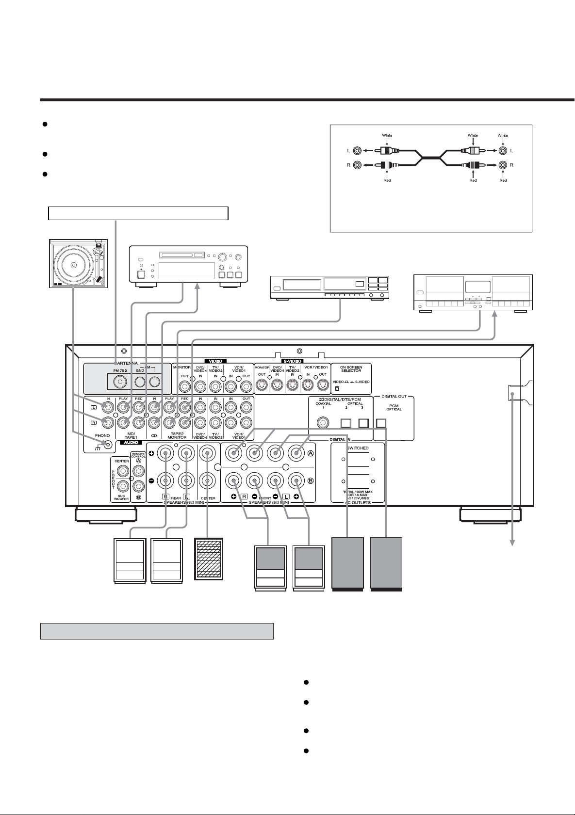
Audio connection cords
To make these connections, use interconnect cords with
RCA plugs. Make sure that you connect the white pinplug to the white jacks (left) and the red pin-plug to the
red jacks (right).
Tape Deck
LINE OUT
LINE OUT
LINE IN
Right
Rear Speaker
Left
Center
Speaker
Right
Front B Speaker
Connecting Audio Equipment
AUDIO signal jacks
PHONO jacks
Connect the turntable’s output jacks to the PHONO IN jacks.
CD IN jacks
Connect the CD player’s output (LINE OUT) jacks to the CD IN
jacks.
To WALL outlet
Left Right
Left
Front A Speaker
MD/TAPE 1 (PLAY/REC) jacks
Connect the MD/TAPE 1 jacks to the MD player or the cassette
deck.
Connect the MD player or cassette deck output (LINE OUT)
jacks to the PLAY jacks.
Connect the MD player or cassette deck input (LINE IN) jacks
to the REC jacks.
TAPE 2 (PLAY/REC) jacks
Connect the cassette deck output (LINE OUT) jacks to the
PLAY (TAPE 2 MONITOR) jacks.
Connect the cassette deck input (LINE IN) jacks to the REC
(TAPE 2 MONITOR) jacks.
-5-
Page 6
CONNECTIONS
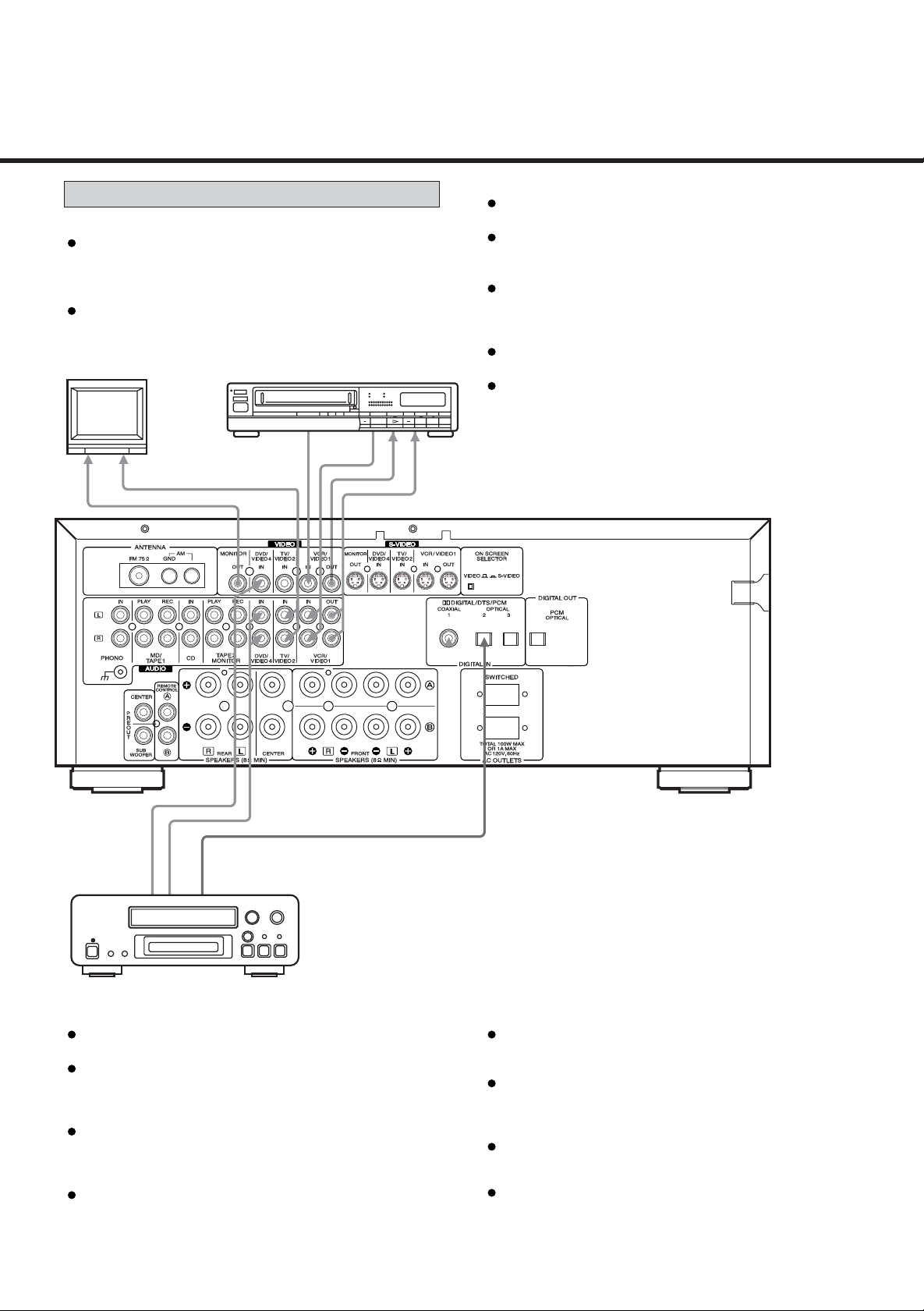
Connecting Video Equipment
AUDIO signal jacks
Connect the video deck (VCR) LINE output (AUDIO
OUT) jacks to the IN (VCR/VIDEO 1) jacks, and the
video deck (VCR) LINE input (AUDIO IN) jacks to the
OUT (VCR/VIDEO 1) jacks.
Connect the TV AUDIO OUTPUT jacks to the VIDEO 2
IN jacks.
TV
VIDEO IN
AUDIO OUT
AUDIO OUT
VIDEO OUT
VCR/VIDEO 1
Video Deck (VCR)
VIDEO IN
AUDIO IN
S-VIDEO signal jacks
Connect the TV monitor S-VIDEO IN jack to the MONITOR
OUT jack.
Connect the video deck (VCR) S-VIDEO OUT jack to the
S-VIDEO VCR IN jack. Connect the video deck (VCR)
S-VIDEO IN jack to the S-VIDEO VCR OUT jack.
Connect the TV or DVD player S-VIDEO OUTPUT jacks to
the S-VIDEO TV/VIDEO 2 IN jack or S-VIDEO DVD/VIDEO 4
IN jack.
Notes :
The FUNCTION (source) selector for the S-VIDEO inputs
and VIDEO inputs work in conjunction with each other.
This unit’s S-VIDEO (IN/OUT) jacks and VIDEO (IN/OUT)
pin jacks have independent circiut structures, so that
video signals input from the S-VIDEO jacks are only
output from the S-VIDEO jack outputs and video signals
input from the VIDEO pin jacks are only output from the
VIDEO pin jack outputs.
VIDEO 4
DVD Player
VIDEO OUT
AUDIO OUT
DIGITAL OUT
(OPTICAL)
VIDEO signal jacks
Connect the TV monitor VIDEO IN jack to the
MONITOR OUT jack.
Connect the video deck (VCR) VIDEO OUT (VIDEO)
jack to the IN (VCR/VIDEO 1) jack.
Connect the video deck (VCR) VIDEO IN jacks to the
OUT (VCR/VIDEO 1) jack.
Connect the DVD player or TV VIDEO OUTPUT jacks
to the VIDEO 2 or VIDEO 4 IN jacks.
DIGITAL OUT (PCM OPTICAL) jack
Connect the CD-R (or MD deck) DIGITAL IN iack to the
DIGITAL OUT jack. (Use the optional optical fiber
cable.)
DOLBY DIGITAL/DTS/PCM DIGITAL IN (1, 2, 3) jacks
If the player is provided with a DIGITAL OUTPUT jack,
connect it to the DIGITAL IN jack. (Use the optional
coaxial cord or optical fiber cable.)
When an optical fiber cable is used for connection,
remove the caps protecting both ends of the optical cable
and the connectors.
Notes :
When both the analog AUDIO IN (VIDEO 2/4) and
DIGITAL IN (1, 2, 3) of the receiver are connected, signals
input to the DIGITAL IN jack (1, 2, 3) have priority.
For better sound quality, we recommend using digital
rather than analog connections when connecting the DVD
player or TV.
-6-
Page 7

Connecting the PRE OUT jacks
This unit is equipped with Subwoofer and Center
PREOUT jacks. These jacks allow connection off an
optional powered subwoofer and connection of the
center channel output to specially equipped TV’s that
will play the center channel through the TV speakers.
Note :
Subwoofer preout signals are not amplified.
Therefore, when using the Subwoofer out jack, you
must use a subwoofer with built-in amplifier.
Center Speaker
Power Amplifier
Notes :
If a speaker is connected directly to the PRE OUT jack
without an amplifier connected, no sound comes
from the speaker.
Subwoofer speakers are optional and are not
required.
Subwoofer with
or
AC OUTLETS
Power Amplifier
Subwoofer without
SWITCHED :
These outlets are only active when the receiver is turned
on.
Caution :
Make sure that the total power consumption of all
equipment connected to the outlets on the receiver
does not exceed 100 watts.
-7-
Page 8
CONNECTIONS
3
2
1
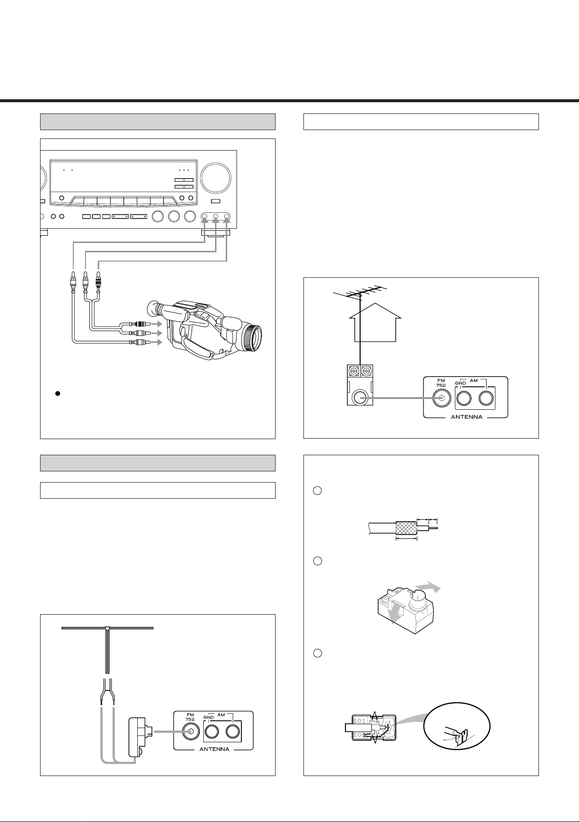
VIDEO CONNECTIONS
VIDEO
AUDIO L
AUDIO R
AUDIO OUT
VIDEO OUT
Video Camera Recorder, etc.
Connect the video camera recorder AUDIO
OUTPUT to the AUDIO (L)/(R) jacks and VIDEO
OUT to the VIDEO jack of the AUX/ VIDEO 3
INPUT.
AUX/
VIDEO 3 INPUT
FM Outdoor Antenna
In an area where FM signals are weak, it will be
necessary to use a 75-ohm unbalanced-type outdoor FM
antenna using the provided matching transformer, as
shown. Generally, a 3-element antenna will be sufficient; if
you live in an area where the FM signals are particularly
weak, it may be necessary to use one with 5 or more
elements.
Connect the coaxial cable of the antenna to the matching
transformer as shown.
After completing connection, plug the transformer into the
“FM 75 ” socket.
Outdoor FM Antenna (75 )
Matching Transforme
(provided)
Connecting Antennas
FM Indoor Antenna
In an area with strong FM signals, the “T”-type FM antenna
provided is sufficient.
Extend this into a “T” shape and connect the two wires at
the base of the “T” to the provided matching transformer,
as shown.
After completing connection, plug the transformer into the
“FM 75 ” socket. Extend the top of the “T” and fix with
thumb tracks, or the like, to a wall or window frame for the
best possible reception.
“T”-type FM Antenna (300 )
(provided)
Matching Transforme
(provided)
How to connect a coaxial cable to the matching
transformer
Strip the cable and dress it as shown.
4mm
3mm
7mm
Press both side tabs outward to remove the
cover.
Wrap the core conductor around the central
metal fixture as shown. Crimp the jagged metal
fixtures so they hold the braided portion using
pliers, etc. Put the cover back in place.
Jagged metal
Insert into slit.
Jagged metal
-8-
Page 9
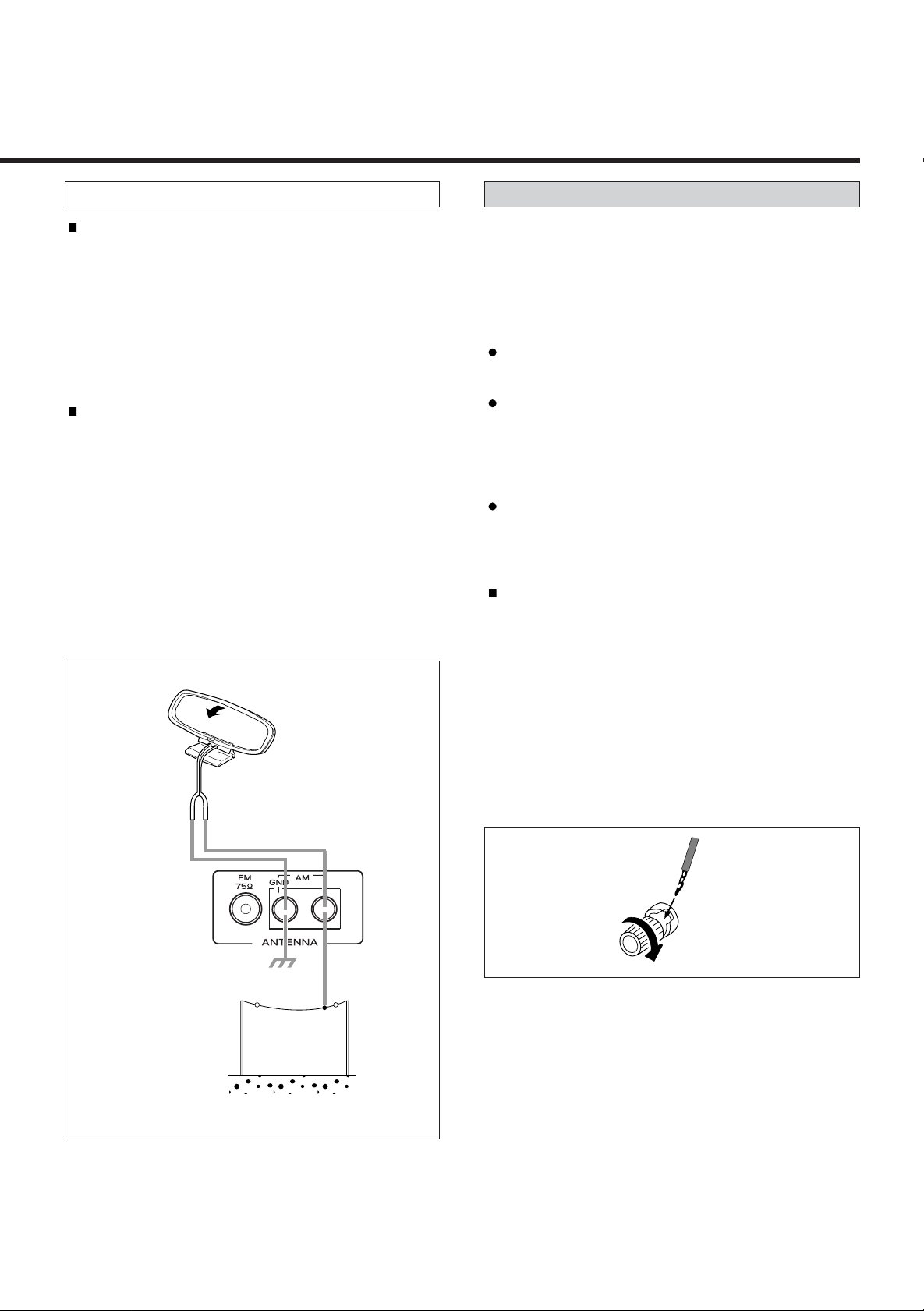
AM Antenna
Connecting Speaker Systems
AM Indoor Loop Antenna
A high-performance AM loop antenna provided with the
receiver is sufficient for good reception in most areas.
Connect the loop antenna’s wires to the AM antenna
terminals as shown. Place the antenna on a shelf, for
example, or hang it on a window frame, etc., in the
direction which gives the best reception, as far away as
possible from the system, speaker cords and the power
cord, to prevent unwanted noise.
AM Outdoor Antenna
If the AM loop antenna provided does not deliver
sufficient reception (because you are too far from the
transmitter or in a concrete building, etc.), it may be
necessary to use an outdoor AM antenna. Use an
insulated wire more than 15 ft (5 m) long, strip one end,
and connect this to the terminal as shown.
For better reception, connect the GND terminal to a
reliable ground.
Note : Even when using an outdoor AM antenna, do not
disconnect the AM loop antenna.
AM Indoor Antenna
(provided)
Caution :
To avoid damaging the speakers by inputting a sudden
high-level signal, be sure to switch the power off before
connecting the speakers.
Connect the cable from each speaker to the
corresponding terminal on the rear of the receiver.
Most speaker cables have different markings, textures
or colors to help you tell the difference between
negative and positive.
Be sure to connect the positive (+) terminal on each
speaker to the positive (+) terminal on the receiver.
Similarly, connect the negative (-) terminal on the
speaker to negative (-) terminal on the receiver.
Notes :
Use speakers with a nominal impedance of 8 ohms or
more.
How to connect
(1) Strip back the cable covering by about 1 cm and
twist the wire strands together.
(2) Turn the terminal cap counterclockwise to loosen it.
The speaker terminal caps cannot be fully removed
from the base.
(3) Insert the wire into the terminal fully and turn the
terminal cap clockwise to securely connect it.
(4) Make sure it is fastened firm by pulling the cable
lightly.
AM Outdoor
Antenna
-9-
Page 10
CONTROLS AND INDICATORS
DELA
REAR
APE 2
MONIT
OPTICAL
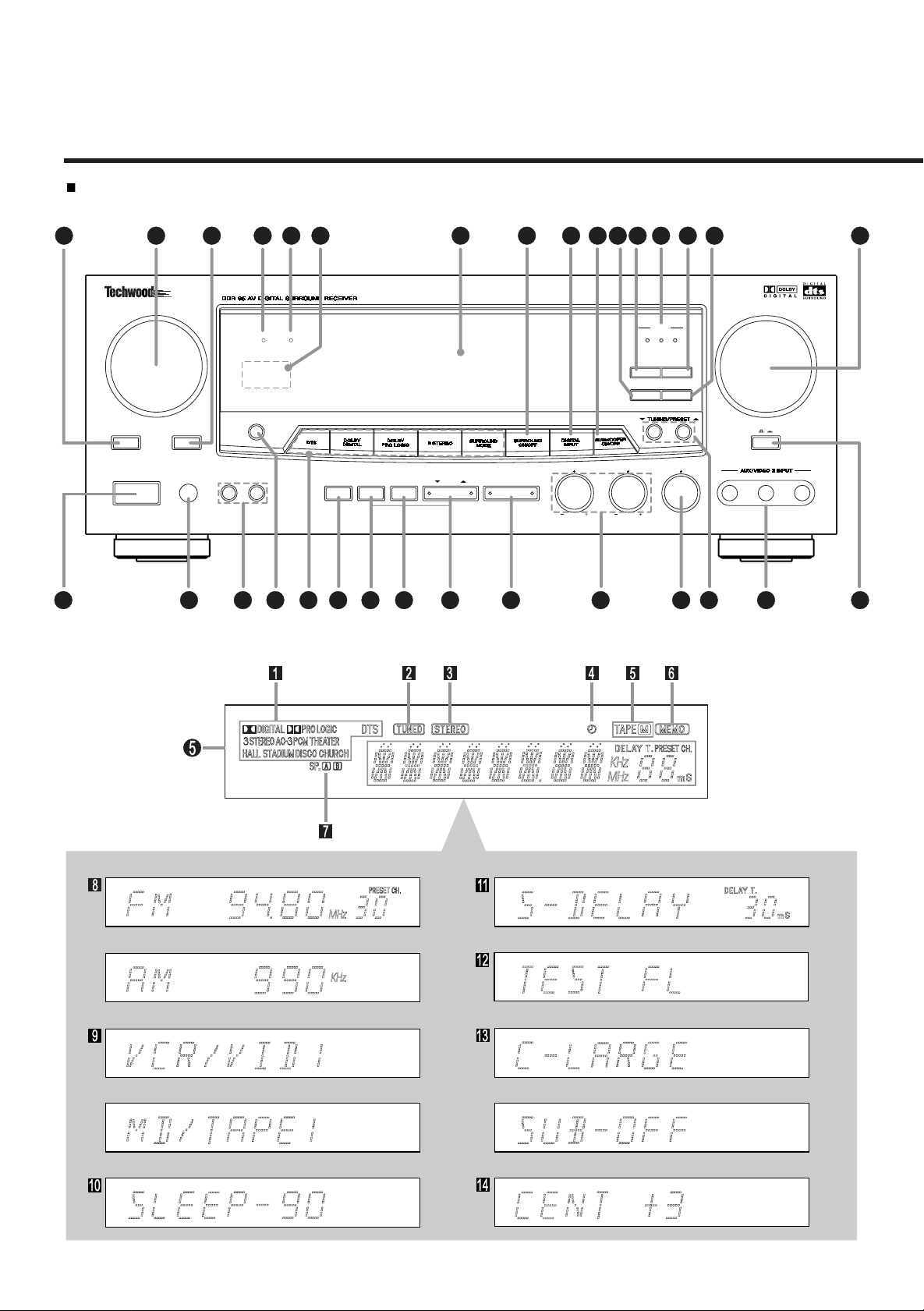
Front Panel
28
MUTING
POWER
ANDBY/ON
2
FUNCTION
MONIT
APE 2
PHONES
142814 5 33 3432 24 7 833 22 11
VOLUME
DIGIT
COAXIAL
SPEAKERS
SLEEP
MUTINGANDBY
TEST
18
SPEAKER
CONFIG
19316 917131
LEVEL
SELECT
ADJUST
CENTER
DELA
TIME
REAR
BASS
TREBLE
OPTICAL
BAND FMMODE
MODE MEMOR
BALANCE
VIDEO
BASS BOOST
AUDIO
12251015232120
Example: Example:
-10-
Page 11

Remote control Unit
14
13
12
11
10
9
8
7
6
5
4
3
2
1
30
29
28
27
26
25
24
23
22
21
20
19
18
17
16
15
4
131211
10
9
8
7
6
5
4
3
2
1
1
VCR
TV
VIDEO 1
VIDEO 2
MD
2
TAPE 1
TAPE 2
MONITOR
6
MEMORY
DIRECT
SCAN
26
27
30
34
32
3
18
TUNING
SEARCH
SEARCH
SKIP
SURROUND
ON/OFF MODE
TEST
C.LEVEL C.LEVEL
TONE
NIGHT
DIGITAL
MODE
INPUT
TAPE
29
33
16
SLEEP
36
AUX
DVD
VIDEO 3
VIDEO 4
CD TUNER PHONO
BAND PRESETCALL
R.PLAY STOP
STOP
PAUSE
REPEAT
1/ALL A-B
OSD
R.LEVEL
ON/OFF
SUB W.
ON/OFF
R.LEVEL
DELAY
CENTER REAR
MASTER
VOLUME
PAUS EREC/PAUSE
F.P LAY
PLAY/
PAUS E
DISC SKIP
SUB W.
LEVEL
MUTING
9
7
31
36
37
23
28
11
FRONT Panel and REMOTE
POWER STANDBY/ON Button
FUNCTION (Source) Selector
SURROUND MODE Buttons
REMOTE SENSOR Window
Multi-Function Display
Numeric Keys (TUNER/CD/DVD)
BAND Selector Button
FM MODE Button
TUNING/PRESET Buttons
BALANCE Control
MASTER VOLUME Control
BASS BOOST Switch
PHONES Jack
TAPE 2 MONITOR Button
1
BASS and TREBLE Controls
SLEEP Button
SPEAKER Select Buttons
TEST TONE Button
SPEAKER CONFIGURATION Button
LEVEL SELECT Button
ADJUST Buttons
MEMORY Button
DELAY TIME Buttons
MODE Button
AUX/VIDEO 3 INPUT Jacks
MEMORY SCAN Button
DIRECT TUNING Button
MUTING Button & Indicator
NIGHT MODE Button
CD/DVD Operation Buttons
TAPE DECK Operation Buttons
SURROUND ON/OFF Button
DIGITAL INPUT Button & Indicator
SUBWOOFER ON/OFF Button
OSD ON/OFF Button
MULTI CONTROL Button
SUBWOOFER LEVEL CONTROL Button
DISPLAY
SURROUND MODE Indicators
TUNED Indicator
STEREO Indicator
TIMER Indicator
TAPE Monitor Indicator
MEMORY Indicator
SPEAKERS Select Indicators
BAND/FREQUENCY Display &
PRESET Channel Display
FUNCTION (Source) Display
SLEEP Time Indicator
Certain buttons on the remote control unit and on the
front panel of the receiver have the same or similar
functions and have the same reference numbers.
The power is turned on/off (standby) by pressing the
POWER button on the remote control unit in standby
mode.
-11-
DELAY TIME Display
TEST TONE Display
SPEAKER CONFIGURATION Display
LEVEL SELECT Display
Page 12

AUDIO OPERATIONS
Note :
The following points apply throughout the “AUDIO and
VIDEO OPERATIONS” sections unless otherwise noted.
To simplify explanations, instructions refer to names
of buttons and controls on the front panel, making no
mention of the use of remote control unit.
To listen to a source other than TAPE 2 (tape deck),
press the TAPE 2 MONITOR button to the OFF
position (the TAPE monitor indicator will not light
in the display).
M
Private listening
For private listening, insert the headphones (1/4-inch
plug) into the PHONES jack.
MUTING Button (on the Remote Control Unit)
Press this to mute the sound from the speakers and
headphones when answering the telephone, etc.
To restore the original volume, press the MUTING button
again. While muting is engaged, the MUTING indicator
will flicker.
Basic Operations
1. Press the POWER button ON.
2. Set the BASS BOOST switch to the OFF position.
3. Adjust the tone as required with the BASS and TREBLE
tone controls. Adjust the balance between the left and
right channels with the BALANCE control.
Sleep Timer Operation
SLEEP Timer Function
This function allows you to preprogram the receiver
to switch its own power off automatically.
You can then enjoy the audio/video system for a
specified amount of time without having to worry
about turning the unit off later.
Each press of the SLEEP button changes the time
indication by 10 minutes.
SLEEP 90 SLEEP 80 •• • SLEEP 10
(Released condition)
To let the remaining time (until power off) appear on
the display while the sleep timer is engaged, press
the SLEEP button once.
4. Select the desired source with the FUNCTION
(source) selector. (The FUNCTION indicator will light.)
5. Select the desired surround mode with the
SURROUND MODE buttons. (The SURROUND indicator
lights in the display.)
6. Select the speaker system to be used with the
SPEAKERS select buttons.
With the unit in the STEREO mode, speakers “A” and
“B” can be selected simultaneously.
If the unit is to be operated in any of the surround
modes, speaker selection is automatically limited
to SPEAKERS A only.
7. Start playing the source component.
8. Gradually turn up the volume to the required level
with the MASTER VOLUME control.
-12-
Page 13

Audio Adjustments
MUTE BALANCE
FUNCTION (Source) Selector
SPEAKERS
POWER
(STANDBY/ON)
POWER STANDBY/ON Button
Press STANDBY/ON button to turn the power on.
Press it again to turn the system off (power standby
mode).
The indicator lights up in power standby mode and goes
out when this unit is turned on.
MUTE Button
Used when you need to reduce the volume for a while.
If you press this button, the volume will reduce to
minimum.
SPEAKER Select Buttons
With the unit in the STEREO mode, SPEAKERS A and B
can be selected simultaneously. If the unit is in any of
the SURROUND MODEs (DTS, DOLBY DIGITAL, DOLBY
PRO LOGIC, 3 STEREO, other SURROUND MODES),
speaker selection is automatically limited to SPEAKERS
A only.
BASS/TREBLE Tone Controls
These two tone controls-BASS and TREBLE- can be
used to obtain a “flat” frequency response or a tone
which suits your individual listening preference. The
Bass control adjusts low frequencies and the TREBLE
control adjusts the high frequencies.
BALANCE Control
This control is used to adjust the balance between the
left and right channels. Normally set to the center
position.
BASS BOOST Switch
Bass frequencies (lows) can be increased by pressing
the bass boost switch. However, do not use the bass
boost feature at high volume levels or permanent
damage may occur to your speakers.
BASS/TREBLE
(T one controls)
BASS BOOST
SURROUND Mode
MASTER VOLUME
DIGITAL INPUT
SURROUND ON/OFF
SURROUND MODE Button
The Surround mode changes whenever you press this
button.
For digital equipment : CD, TV/ VIDEO 2, AUX/ VIDEO 3,
DVD/VIDEO 4. (when selected digital 1, 2 or 3 input.)
DTS Dolby Digital PRO-LOGIC 3 STEREO
CHURCH DISCO HALL STADIUM THEATER
For analog equipment : TUNER (AM/FM), TAPE 1. TAPE
2 MONITOR, VCR 1.
PRO-LOGIC 3 STEREO THEATER STADIUM
CHURCH DISCO HALL
CAUTION
You can not select DTS/DOLBY DIGITAL mode in
Analog mode. To select DTS/DOLBY DIGITAL mode,
you should select digital 1, 2 or 3 mode with the
DIGITAL INPUT button.
SURROUND ON/OFF (STEREO) Button
Press to switch from surround mode to stereo mode.
When operating unit in Dolby Digital mode, this button
operates as down mix (2 channel) function and the
“STEREO” indicator will light up.
DIGITAL INPUT (SELECT) Button
Press this button to switch the digital signal. (When CD,
TV/ VIDEO 2, AUX/ VIDEO 3, DVD/ VIDEO 4 selected.)
When DTS/Dolby Digital Mode
Digital 1 Digital 2 Digital 3
(coaxial) (optical) (optical)
When PRO LOGIC, 3 STEREO, other Surround, Stereo
Mode
Digital 1 Digital 2 Digital 3 Analog
(coaxial) (optical) (optical)
MASTER VOLUME CONTROL
Adjust the overall sound volume from the front, center,
(sub woofer) and rear speakers with this control.
Pre-Out (center, sub woofer) can also be controlled.
-13-
Page 14

AUDIO OPERATIONS
Radio Reception
Auto Tuning
FM MODE
POWER ON
1. Select the TUNER mode by turning the FUNCTION
selector.
2. Select AM or FM by pressing the BAND selector
button.
3. Press the MODE button to change to TUNING mode.
(The PRESET CH. indicator disappears from the display).
This button is used to select Tuning or Preset scan
mode.
4. Press and hold the UP or DOWN TUNING button
(between 0.5 to 2 seconds).
The next station broadcasting at a frequency
higher or lower than that of the current
station is automatically detected and tuned in.
By pressing and holding the TUNING button for
longer than 2 seconds, it will continue to control
(three times faster than normal speed).
Manual Tuning
FM MODE
POWER ON
Manual Tuning is generally used to tune to stations
broadcasting a signal that is too weak to be received by
Auto Tuning.
1. Select the TUNER mode by turning the FUNCTION
selector.
2. Select AM or FM by pressing the BAND selector
button.
3. Press the MODE button to change to TUNING mode.
(The PRESET CH. indicator disappears from the
display).
4. When the UP or DOWN TUNING button is pressed
momentarily (0.5 second or less), the frequency
changes by a fixed step (see STEPS below).
STEPS
FM : 100-kHz steps
AM : 10-kHz steps
FM MODE Button
Pressing this button alternates between Stereo
mode and Mono mode.
• Stereo
FM stereo broadcasts are received in stereo and
the STEREO indicator lights in the display.
If FM broadcasts with weak signal strength are
received, the FM muting function works
automatically to cut the signals.
• Mono
To compensate for weak FM stereo reception,
select this mode. Reception will now be forced
monaural, reducing unwanted noise.
TUNED Indicator
“TUNED” appears in the display when a broadcast
is correctly tuned in.
-14-
Page 15

Direct Tuning
3
2
1
Tuning
Using this method, the required frequency is input
directly, using the numeric keys on the remote control
unit.
VCR
VIDEO1
MD
TAPE 1
MEMORY
SCAN
SEARCH
TV
VIDEO2
TAPE 2
MONITOR
DIRECT
TUNING
TAPE
AUX
DVD
VIDEO3
VIDEO4
CD TUNER PHONO
BAND PRESET CALL
R.PLAY STOP
PAUS EREC/PAUSE
F.P LAY
PLAY/
1. Press the TUNER button.
2. Select AM or FM by pressing the BAND selector
button.
3. Press the DIRECT TUNING button on the remote control
unit, “DIRECT IN” appears on the display for a few
seconds.
“FM ---.---MHz” or “AM----KHz” appears on the display.
4. Input the frequency of the broadcast you want to hear
with the numeric keys.
If you press the DIRECT TUNING button again or
without pressing any button for 30 seconds, Direct
tuning is released.
FM : 100-kHz steps
AM : 10-kHz steps
Ex.: FM 107.50 MHz
1
57
0
This feature is used to store FM, AM broadcasting from
Channel 1 to 30 respectively. You can set 30 AM and 30
FM stations in memory.
Automatic Memory Presetting
POWER ON
1. Select the TUNER mode by turning the FUNCTION
selector.
2. Select AM or FM by pressing the BAND selector
button.
3. Press and hold the MEMORY button for more than 1.5
seconds.
The start frequency will show in the display.
• 87.5 MHz in FM, 530 kHz in AM.
The frequency and display will automatically scan.
• 100 kHz steps for FM, 10 kHz steps for AM.
The frequency shown in the display will rapidly
change. As each station is located a preset number
will appear in the display indicating which preset
MEMORY button has been assigned to the station
located. The scanning process will continue to
operate in this fashion until 30 stations have been
found and entered into the preset memory or
when there are no more stations to be found on
the waveband chosen. The memory indicator will
extinguish and let you hear the first station to be
memorized.
To listen to the memorized station select the band
required and press the numeric keys 1, 2, 3 etc.
4. The last memorized channel of each band will be
displayed when Auto Memory is completed.
You can Check the programmed frequencies with
Ex.: AM 1000 kHz
1000
PRESET UP, DOWN button.
-15-
Page 16

AUDIO OPERATIONS
Manual Memory Presetting
POWER ON
1. Select the TUNER mode by turning the FUNCTION
selector.
2. Select AM or FM by pressing the BAND selector
button.
3. Press the MODE button to change to TUNING mode.
(The PRESET CH. indicator disappears from the display).
Listening to Records and Compact Discs
POWER ON
1. Select the PHONO or CD mode by turning the
FUNCTION selector.
2. Play the turntable (with a moving magnet cartridge)
or CD player.
T urntable
or
CD Player
4. Select the frequency you want to preset by pressing
TUNING/PRESET UP or DOWN button.
5. Press the MEMORY button briefly, MEMORY display
will blink at an interval of 1 second.
6. While the MEMORY indicator is lit, press the numeric
key(s) (on the remote control unit) to input the
channel number in which the data (AM or FM band
and frequency) for the broadcast is to be stored (or
press the PRESET button to the desired selection then
press the MEMORY button again).
Recalling Frequencies
Press the numeric key(s) (o n the remote control unit)
corresponding to the channel number to tune directly to
a broadcast.
Using the Memory Scan function
(on the remote control unit)
When the MEMORY SCAN button is pressed, the preset
channels in which frequencies in the band (AM or FM)
selected have been stored are scanned at 5-second
intervals. When you hear a broadcast you want to listen
to, release the Memory Scan function by pressing the
MEMORY SCAN button again.
Playing MD/TAPE 1 Deck
POWER ON
MD Deckor Tape Deck 1
1. Select the MD/TAPE 1 mode by turning the
FUNCTION selector.
2. Operate the MD deck or tape deck (TAPE 1) for playback.
“Back-up” memory function
This function saves the already preset station
memories, and “Most-recent” memory function, even in
the event of a cut-off of power supply for up to 3 days.
- 16 -
Page 17

Playing TAPE 2 Deck
Dubbing from TAPE 2 to MD/TAPE 1
TAPE Indicator Lit
POWER ON
Tape Deck 2
1. Set the TAPE 2 MONITOR button to ON ; the TAPE
monitor indicator will appear in the display.
2. Operate tape deck (TAPE 2) for playback.
M
Recording a Source
Recording program source
You can record a program source such as a record or
Compact Disc onto a cassette deck connected to the
TAPE 2 REC jacks.
TAPE Indicator Lit
POWER ON
Recording
Tape Deck 1Tape Deck 2
1. Set the TAPE 2 MONITOR button to ON.
2. Turn the FUNCTION selector, and select a source
(except MD/TAPE 1).
3. Start playback on the tape deck (TAPE 2).
4. Start recording on the tape deck (MD/TAPE 1).
When copying with a double cassette deck, refer to
the operating instructions for the cassette deck.
TAPE 2 MONITOR OFF
POWER ON
Source
component
1. Turn the FUNCTION (source) selector corresponding
to the source to be recorded.
Make sure the TAPE 2 MONITOR button is set to
OFF.
2. Play the source.
3. Operate the tape deck (TAPE 2) for recording.
Recording
Tape Deck 2
Tape Monitoring
If the tape deck has separate record and playback heads,
during recording, the recorded sound can be heard from
the speakers with the TAPE 2 MONITOR button set to
ON.
- 17 -
Page 18

VIDEO OPERATIONS
Playing Video Sources
Note :
For playing video software using a certain Surround
Effect function, refer to the SURROUND EFFECTS
section.
Video signals
Audio signals
POWER ON
VCR/VIDEO 1
TV/VIDEO 2
DVD/VIDEO 4
AUX/VIDEO 3
Recording with a Video Deck
Tape Dubbing (from TV/VIDEO 2, AUX/VIDEO 3
or DVD/VIDEO 4 to VCR/VIDEO 1)
TAPE 2 MONITOR OFF
POWER ON
TV/VIDEO 2
VCR/VIDEO 1
1. Turn the FUNCTION (source) selector to select the
VIDEO source (TV/VIDEO 2, AUX/VIDEO 3 or
DVD/VIDEO 4) to be recorded.
Video signals
Audio signals
AUX/VIDEO 3DVD/VIDEO 4
1. Select the VCR/VIDEO 1, TV/VIDEO 2, AUX/VIDEO 3 or
DVD/VIDEO 4 mode by turning the FUNCTION
selector.
2. Play the component corresponding to the FUNCTION
selected.
3. The picture from the video source can be seen on the
TV and the sound from the video source will be heard
from the speakers if the video device has been
connected to the receiver as shown on page 6.
If video devices have been connected directly to the
television, additional steps may be required.
Make sure the TAPE 2 MONITOR button is set to
OFF.
2. Play back the source (TV/VIDEO 2, AUX/VIDEO 3 or
DVD/VIDEO 4).
3. Operate VCR/VIDEO 1 for recording. Video/audio
signals from the selected VIDEO component
(TV/VIDEO 2, AUX/VIDEO 3 or DVD/VIDEO 4) can be
dubbed to VCR/VIDEO 1.
Note :
When tape dubbing is performed, be sure to con-
nect the LINE OUT (analog audio output).
S.A.V.E. (Second Audio Source for Video
Editing) SYSTEM Function
This feature lets you replace the sound from a VCR with
sound from an AUDIO source such as CD during video
signal dubbing.
1. Select the video source (TV/VIDEO 2, AUX/VIDEO 3 or
DVD/VIDEO 4) by turning the FUNCTION selector.
Wait for more than 5 seconds and then select the
audio source with the FUNCTION selector.
2. Operate the selected video component and audio
component for playback, respectively.
3. Now you can watch the picture from the video
component on the TV, and listen to the sound from
the audio component through the speakers.
4. Operate VCR/VIDEO 1 for recording.
- 18 -
Page 19

SURROUND EFFECTS
When you use the surround function, the sound creates a
“live” atmosphere such as that experienced in movie
theaters, disco, stadium and concert halls.
Surround Modes
This unit is provided with the following surround
modes, which can be selected using the SURROUND MODE
switches. Select the appropriate SURROUND MODE
according to the program source.
DTS (Digital Theater System)
Allows you to enjoy 5.1 (or 6) discrete channels of high
quality digital audio from DTS program sources bearing the
“ “ or “HIGH DEFINITION SURROUND” trademark
such as discs, DVD and compact discs, etc. DTS Digital
Surround delivers up to 6 channels of transparent audio
(which means identical to the original masters) and results
in exceptional clarity throughout a true 360˚ soundfield.
The term DTS is a trademark of DTS Technology, LLC.
Manufactured under license from DTS Technology, LLC.
Note : The DTS program sources should be played back in
the DTS mode. If not, it will sound like continuous
noise.
DOLBY PRO LOGIC
Use this mode when playing movie or music video software
which carries the DOLBY SURROUND mark.
This mode provides the effect of being in a movie theater or
live concert house-an effect with an intensity which can only
be obtained through DOLBY PRO LOGIC SURROUND.
The main feature of DOLBY PRO LOGIC SURROUND is that
the separation between the various channels is significantly
improved from the 3 dB of previous systems to 26-40 dB.
As a result, the effect of the front/back/ left/right movement of
the sound image, as well as the sense of fixed position in the
sound image, is much clearer and more dynamic than before.
In addition, movie dialogue and other sounds which should
naturally be heard from the center are output through an
independent center channel, providing a high degree of focus
for dialogue.
3 STEREO
Front speakers receive rear (surround) speaker signals in
addition to front speakers signals. Center speaker works
similarly as that of Dolby Pro Logic mode. In this way, you can
enjoy playback sound having superior sound positioning
without using rear channel speakers.
HALL Surround
DOLBY DIGITAL Surround
The Dolby Digital surround format lets you enjoy up to 5.1
channels of digital surround sound from a Dolby Digital
program source. If you connect a DVD player or an LD
player with a DOLBY DIGITAL output to the DOLBY DIGITAL
input jack on a surround receiver/amplifier or surround
processor and play DVD or laser discs with ( ) mark,
you can enjoy evenbetter sound quality, greater spatial
accuracy, and improved dynamic range. This is because
Dolby Digital delivers up to 5 totally discrete, full frequency
audio channels (front left and right, center, and surround left
and right), plus 0.1 channel called LFE* (bass-only effects
channel).
Dolby Digital is a system developed by Dolby Laboratories
that transmits 5.1 channels of digital signals. The surround
system developed for movie theaters using this system is
called “Dolby SR-D “Surround Digital”. Because each
channel is completely independent, a realistic sound field
with a “three-dimensional” feel is achieved which gives the
sound a sense of distance, movement and relative position,
creating a surprisingly real and powerful sense of presence.
Some Dolby Digital programs carry information that allow
you to compress the dynamic range of sound track, without
degrading the sound quality, for softer sound effects when
you listen late at night.
* LFE = Low Frequency Extension
This channel delivers separate non-directional bass
signals to the subwoofer for more dynamic deep
bass sound effects.
When playing recordings of live music, this mode provides a
feeling similar to actually being in a concert hall. When this
mode is selected, the normal program source is directed to
the main speakers and a reverberated sound is directed to the
surround speakers. This mode is suited to program sources
which contain a large amount of reverberation.
THEATER Surround
This mode provides a three dimensional effect similar to that
of movie theater. With this mode, you can enjoy a surround
effect similer to Dolby Surround sound even when playing a
video program which is not encoded with the Dolby Surround
system.
DISCO Surround
Gives a greatly expanded feel to powerful music such as
dance or rock.
STADIUM Surround
The reverberation of this mode produces a sound field which
recreates the sound of a stadium.
CHURCH Surround
This mode provides the reverberant ambiance of a church,
which can enhance choral work, as well as adding a rich
ambient effect to “dry” studio recordings.
- 19 -
Page 20

SURROUND EFFECTS
Speaker Positioning
This installation positions of speakers differ according to
the size, and acoustics of the listening room. While
actually listening to a program source, try various
speaker positions to determine which layout provides
the best surround effect.
Speaker layout example when using SURROUND
MODE
Front Speakers
Center Speaker
Subwoofer
Rear Speakers
Front speakers : Place to the front left and right of the
listening position. Front speakers are
required for all surround modes.
Center speaker : Place directly above or below the
television. This speaker stabilizes the
sound image and helps recreate
sound motion. Be sure to connect a
center speaker when using the 3
STEREO mode.
Rear speakers : Place left and right behind the
listening area.
These speakers recreate sound
motion and atmosphere. Required
for surround playback.
For best results, do not install the
rear speakers too far behind the
listening position and install them at
or above the level of the listener’s
ears. It is also effective to direct the
rear speakers towards a wall or
ceiling to further disperse the
sound.
Subwoofer : Reproduces powerful deep bass
(OPTIONAL)
sounds. A Subwoofer is not required
but may be added as an option.
Speaker Configuration
POWER ON
It is important to perform speaker configuration prior to
using the decoder. This allows the unit to sense the
available speakers and automatically select decoding
modes. It is possible to receive multi-channel surround
sound without a center speaker, but for best results with
DTS, Dolby Pro Logic and Dolby Digital decoding, at least 5
speakers (Left, Center, Right, Left Rear and Right Rear)
should be used.
1. Each press of the SPEAKER CONFIGURATION
button will change the desired Speaker Configuration
shown on the display. (ex.: “F-LARGE”, “F-SMALL”,
“C-LARGE”, “C-NONE”, “S-LARGE” etc.)
2. Use the ADJUST ( ) buttons to set the appropriate
status.
CENTER SPEAKER Mode
- LARGE : Use this mode with a large center speaker.
The center channel’s output is full range.
- SMALL : Use this mode with a small center speaker.
- NONE : Use this mode if there is no center speaker.
The center channel signal will be divided between
the front L and R speakers.
REAR (SURROUND) SPEAKER Mode
- LARGE : Choose if a large speaker is used or if a
subwoofer is connected in parallel.
The rear channels output will be full range.
- SMALL : Choose if small speakers are used.
When using small speakers, it is recommened that a
powered Subwoofer be added to play low frequencies.
FRONT SPEAKER Mode
- LARGE : Choose if large speakers are installed.
Front channel output will be full range.
- SMALL : Choose if compact speakers are used.
Note : When LFE/Bass Out is set for FRONT, the
front channels full range is output to the front
speakers even if the front speaker mode is set to
SMALL.
a. When in DTS/Dolby Digital Mode,
Choose from:
Front Speaker : LARGE SMALL
Center Speaker : LARGE SMALL NONE
Rear Speaker : LARGE SMALL
- 20 -
Page 21

b. When in Dolby PRO LOGIC Mode,
Choose from:
Front Speaker : LARGE SMALL
Center Speaker : LARGE SMALL NONE
Rear Speaker : LARGE SMALL
c. When in 3 Stereo Mode, Choose from:
Front Speaker : LARGE SMALL
Center Speaker : LARGE SMALL
SUBWOOFER output
- SUB-ON : Choose if a subwoofer is used.
Low frequencies of 90Hz and below in the LFE
channel and other selected channels are output to
the subwoofer.
- SUB-OFF : Choose if no subwoofer is used.
Low frequencies of 90Hz and below in the LFE
channel and other selected channels are distributed
between the front L and R speakers.
Delay Time
Channel Level
POWER ON
Test tones are automatically emitted from the different
speakers when the test tone button is pressed. Listen to
the test tone and adjust the volume level of each
speaker so that they produce the test tone at the same
volume level.
1. Press the TEST TONE button (DTS/Dolby Digital/
Dolby PRO LOGIC and 3 stereo Mode).
The test tone is emitted from each speaker in the
following order at 2-second intervals.
POWER ON
1. The delay time can be simultaneously set for the
DOLBY DIGITAL/DOLBY PRO LOGIC modes using the
DELAY TIME (CENTER/REAR) button. When you
adjust the delay time in the DOLBY DIGITAL mode, an
additional 15 ms is automatically added to the
surround channels in the DOLBY PRO LOGIC mode.
The current setting is shown on the display.
Delay Time Setting
Surround Mode Adjustable Range
DOLBY DIGITAL 0 ~ 15 ms in 1 ms step (S-Delay)
0 ~ 5 ms in 1 ms step (C-Delay)
DOLBY PRO LOGIC 15 ~ 30 ms in 1 ms step (S-Delay)
In the surround modes, the sound from the rear
speakers should be delayed slightly, relative to that
from the front speakers. The optimum delay time will
depend on acoustic properties, whether the walls and
furnishings reflect or absorb sound, etc.
It is recommended that you try different delay times to
obtain the best effect. The delay is digitally synthesized,
for the highest sound quality with minimum noise and
distortion.
The delay time can be set independently for each
surround mode using the DELAY TIME button, with the
current setting shown in the display.
FL C FR RR RL SUB
2. Each press of the LEVEL SELECT button during test
tone emission allows you to manually skip to the
speaker you want to listen to.
3. Use the ADJUST ( ) buttons to adjust the
volume until the sound level from each speaker is the
same. The volume can be adjusted in units to 1 dB
from -10 dB to +10 dB.
4. Press the TEST TONE button again to turn it off.
Note :
If certain speakers are not being used, (for example,
no center speaker) the noise sequencer will automatically skip over that channel.
Press the LEVEL TRIM button for more than 2
seconds to reset the level to its original setting.
- 21 -
Page 22

SURROUND EFFECTS
BACK-UP SYSTEM
Playing Surround Sound
POWER ON
1. Select the desired surround mode.
2. Press the SURROUND ON/OFF button.
3. Start playing the video software.
When a Dolby Digital format signal is input, the
surround mode automatically switches to the DOLBY
DIGITAL mode.
Back-up Memory Function
This function stores the preset memory and most-recent
memory functions. In the event of a power failure, or if
the power cord of this unit is disconnected from the
electric outlet, the back-up memory will save the preset
memory and most-recent memory functions for
approximately 3 days.
If the power supply is interrupted for 3 days or longer,
the memory settings will be erased.
When to Use RESET Function
1. When this system is subjected to an electrical shock.
2. When the power is irregular.
In these cases, try the following (in POWER ON,
VCR/VIDEO 1 function):
- Front PANEL -
4. Adjust the volume.
NIGHT MODE function (on the Remote
Control Unit)
When very dynamic movie soundtracks are played at
low volume, such as late at night, you can use Night
Mode to apply appropriate compression so that lowlevel program content is not lost and high level effects
are restrained.
Manufactured under license from Digital Theater
System, Inc. US Pat. No. 5,451,942 and other worldwide patents issued and pending. “DTS”,”DTS
Digital Surround”, are trademarks of Digital Theater
System, Inc.
Copyright 1996 Digital Theater System, Inc.
All Rights Reserved.
Manufactured under license from Dolby Laboratories.
Dolby Pro Logic and the double-D Symbol are
trademarks of Dolby Laboratories.
Confidential Unpublished Works.
© 1992-1997 Dolby Laboratories, Inc.
All rights reserved.
Press the MODE button for more than 5 seconds.
Note :
When the MODE button is pressed in VCR/VIDEO 1
function or standby mode, for more than 5
seconds, all the memory will be cancelled.
- 22 -
Page 23

OSD (ON SCREEN DISPLAY)
When your Techwood AV Digital Surround Receiver is
connected to a television, you can operate the unit with
the remote control by making selections from on-screen
menus. If a menu remains on the screen for a period of
time without a selection being made, the display will
disappear. Most menus disappear after 20 seconds.
Important:
The on-screen display will not operate unless
the receiver is connected to the television with a video
cable from the monitor out jacks.
Before using the on-screen display, the ON SCREEN
SELECTOR SWITCH on the rear panel of the receiver must
be set to the type of video connection being used to supply
video signal from your receiver to your TV monitor.
VIDEO : Set the switch to this position when using the
yellow VIDEO MONITOR OUT jack.
S-VIDEO : Set the switch to this position when using
the 4 pin S-VIDEO MONITOR OUT jack.
The on-screen display will only appear when the video
signal matches the type of signal selected with the
selector switch.
OSD “ON” POSITION :
1) When you turn your receiver's power on or change its
functions, a display appears on your television screen
showing the current status of the system, including the
type of video and audio input being monitored, the
type of audio output and the status of the Tape 2
monitor. If the Tape 2 monitor is ON, the sound being
heard is the sound being recorded through the Tape 2
channel. If the Tape 2 monitor is OFF, the sound being
heard is coming directly from the source of the sound.
2) When the OSD ON/OFF button on the remote control is
pressed, a display appears which shows the current
status of the input being monitored:
SURROUND
ON/OFF MODE
TEST
C.LEVEL C.LEVEL
TONE
DIGITAL
NIGHT
INPUT
MODE
SLEEP
R.LEVEL
SUBW.
ON/OFF
R.LEVEL
OSD
ON/OFF
SUBW.
LEVEL
DELAY
CENTER REAR
MASTER
VOLUME
MUTING
To change these settings, press the ENTER button to bring
up the MAIN MENU. This is the only operation that can
be performed on this menu, which will disappear after 7
seconds without input.
3) When MAIN MENU appears, move the arrow cursor
using the up/down buttons located above and below
the ENTER button to select the function you wish to
change, then press ENTER.
VCR
VIDEO1
MD
TAPE 1
TV
VIDEO2
TAPE 2
MONITOR
AUX
DVD
VIDEO3
VIDEO4
CD TUNER PHONO
With this display on-screen, the type of input being
monitored can be changed by pressing the appropriate
key in the top section of the remote control. This menu
will remain on the screen for only 7 seconds without
input.
SURROUND
ON/OFF MODE
TEST
C.LEVEL C.LEVEL
TONE
DIGITAL
NIGHT
INPUT
MODE
SLEEP
R.LEVEL
SUBW.
ON/OFF
R.LEVEL
OSD
ON/OFF
SUBW.
LEVEL
DELAY
CENTER REAR
MASTER
VOLUME
MUTING
This menu will remain on the screen for 20 seconds
without input. If it disappears before you have made a
selection, press the OSD ON button then the ENTER
button to bring it back.
- 23 -
Page 24

OSD (ON SCREEN DISPLAY)
4) Entering INPUT SELECTOR from the MAIN MENU
brings up a display that allows you to select the video
input that you'd like to monitor. Move the arrow using
the up/down buttons, then change the input source
with the left/right buttons located on either side of the
ENTER button.
SURROUND
ON/OFF MODE
TEST
C.LEVEL C.LEVEL
TONE
NIGHT
DIGITAL
MODE
INPUT
SLEEP
R.LEVEL
SUBW.
ON/OFF
R.LEVEL
OSD
ON/OFF
SUBW.
LEVEL
DELAY
CENTER REAR
MASTER
VOLUME
MUTING
To get back to the MAIN MENU move the arrow to GO TO
MAIN MENU and press ENTER.
5) Entering DIGITAL INPUT from the MAIN MENU brings
up a menu that allows you to select the audio input
you'd like to monitor.
SURROUND
ON/OFF MODE
TEST
C.LEVEL C.LEVEL
TONE
NIGHT
DIGITAL
MODE
INPUT
R.LEVEL
SUBW.
ON/OFF
R.LEVEL
OSD
ON/OFF
SUBW.
LEVEL
DELAY
CENTER REAR
MASTER
VOLUME
An asterisk (*) appears opposite the input currently
selected. To change this selection, move the arrow with
the up/down keys to the input you want and press ENTER.
The asterisk (*) will now appear opposite the input you
have selected.
SURROUND
ON/OFF MODE
TEST
C.LEVEL C.LEVEL
TONE
NIGHT
DIGITAL
MODE
INPUT
SLEEP
R.LEVEL
SUBW.
ON/OFF
R.LEVEL
OSD
ON/OFF
SUBW.
LEVEL
DELAY
CENTER REAR
MASTER
VOLUME
MUTING
For PHONO, TUNER, MD/TAPE 1, and VCR/VIDEO 1
inputs, ANALOG is the only selection available.
For TV/VIDEO 2, AUX/VIDEO 3, DVD/VIDEO 4 and CD,
ANALOG or DIGITAL may be selected. However you must
have DIGITAL audio connections and a DIGITAL or DTS
source to playback in DIGITAL. (i.e. DVD, SATELLITE, CD,
MD) Otherwise no sound will be heard.
To get back to the MAIN MENU move the arrow with the
up/down keys to GO TO MAIN MENU and press ENTER.
6) Entering SURROUND MODE from the MAIN MENU
brings up a menu that allows you to select the
acoustical effects you'd like to use.
SLEEP
MUTING
The choices available to you will vary according to the
function and type of input you are monitoring.
- 24 -
Page 25

When you are monitoring PHONO, TUNER, MD/TAPE
1, or VCR/VIDEO 1, use the left/right buttons to select
one of these SURROUND MODE choices:
When you are monitoring ANALOG input, use the
left/right buttons to select one of these SURROUND
MODE choices:
SURROUND
ON/OFF MODE
TEST
C.LEVEL C.LEVEL
TONE
NIGHT
DIGITAL
MODE
INPUT
SLEEP
R.LEVEL
SUBW.
ON/OFF
R.LEVEL
OSD
ON/OFF
SUBW.
LEVEL
DELAY
CENTER REAR
MASTER
VOLUME
MUTING
When you are monitoring TV/VIDEO 2, AUX/VIDEO 3,
DVD/VIDEO 4, or CD, use the left/right buttons to select
one of these SURROUND MODE choices:
SURROUND
ON/OFF MODE
TEST
C.LEVEL C.LEVEL
TONE
NIGHT
DIGITAL
MODE
INPUT
SLEEP
R.LEVEL
SUBW.
ON/OFF
R.LEVEL
OSD
ON/OFF
SUBW.
LEVEL
DELAY
CENTER REAR
MASTER
VOLUME
MUTING
SURROUND
ON/OFF MODE
TEST
C.LEVEL C.LEVEL
TONE
NIGHT
DIGITAL
MODE
INPUT
SLEEP
R.LEVEL
SUBW.
ON/OFF
R.LEVEL
OSD
ON/OFF
SUBW.
LEVEL
DELAY
CENTER REAR
MASTER
VOLUME
MUTING
When you have selected DOLBY DIGITAL as your
SURROUND MODE, the menu will include options for
adjusting the DELAY TIME for each speaker channel.
Using the right/left buttons, the delay for the CENTER
speaker can be set from 0 to 5ms and the REAR speakers
can be set from 0 to 15 ms.
In the DOLBY PRO LOGIC mode, the REAR speakers can
be set for 15 to 30 ms of delay. NIGHT MODE, which
compresses the audio signal to allow all sounds to be
heard at a lower volume, can be changed only in the
DOLBY DIGITAL mode:
To get back to the MAIN MENU move the arrow to GO TO
MAIN MENU and press ENTER.
NOTE:
You must have digital audio connections and a
dolby digital or dts source to playback in dolby digital or
dts.
7) Entering SPEAKER CONFIGURATION from the MAIN
MENU brings up a menu that allows you to select the
speaker configuration in use.
- 25 -
Page 26

OSD (ON SCREEN DISPLAY)
Your choices will vary according to the SURROUND
MODE you are using. Use the up/down buttons to move
the arrow and the right/left buttons to make your
selections.
SURROUND
ON/OFF MODE
TEST
C.LEVEL C.LEVEL
TONE
DIGITAL
NIGHT
INPUT
MODE
SLEEP
R.LEVEL
SUBW.
ON/OFF
R.LEVEL
OSD
ON/OFF
SUBW.
LEVEL
DELAY
CENTER REAR
MASTER
VOLUME
MUTING
8) Entering LANGUAGE from the MAIN MENU brings up a
menu that allows you to change the language of the on
screen menus.
An asterisk (*) appears opposite the language currently
selected. To change this selection, move the arrow with
the up/down keys to the language you want and press
ENTER. The asterisk (*) will now appear opposite the
language you have selected.
In the case of DTS or DOLBY DIGITAL, your choices
are:
FRONT: SMALL or LARGE
CENTER: NONE or SMALL or LARGE
REAR: SMALL or LARGE
SUB: ON or OFF
In the case of DOLBY PRO LOGIC, your choices are:
FRONT: SMALL or LARGE
CENTER: NONE or SMALL or LARGE
REAR: SMALL or LARGE
SUB: ON or OFF
In the case of 3 STEREO, your choices are:
FRONT: SMALL or LARGE
CENTER: SMALL or LARGE
REAR: NONE
SUB: ON or OFF
- 26 -
Page 27
AUTOMATIC OSD FUNCTIONS
If the receiver is connected to a television with a
video cable from the monitor out jacks, the following
functions when used , will appear on-screen
automatically.
Once this display appears, pressing the CENTER or REAR
DELAY TIME, or the CENTER or REAR LEVEL buttons will
enable you to change the function of the button pressed
using the right/left buttons. Pressing SUB W ON/OFF or
SUB W LEVEL will allow you to change the sub-woofer
setting by pressing the same button a second time.
Without input, the display will disappear in 7 seconds.
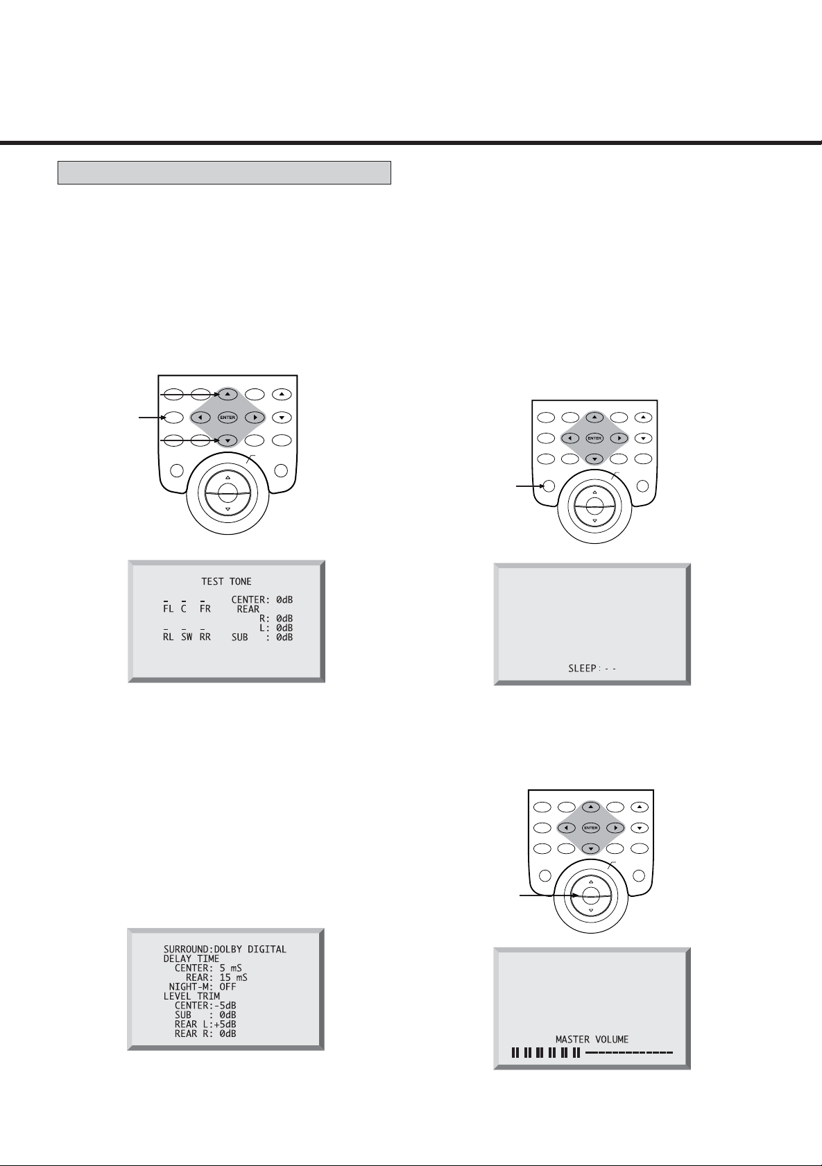
Test Tone: In DOLBY DIGITAL, DOLBY PRO LOGIC
SURROUND, or 3 STEREO MODES, pressing the TEST
TONE button on the remote controller brings up a display
which allows you to adjust the relative volume of front,
rear and center speaker channels.
SURROUND
ON/OFF MODE
TEST
C.LEVEL C.LEVEL
TONE
NIGHT
DIGITAL
MODE
INPUT
SLEEP
R.LEVEL
SUB W.
ON/OFF
R.LEVEL
OSD
ON/OFF
SUB W.
LEVEL
DELAY
CENTER REAR
MASTER
VOLUME
MUTING
Sleep: Pressing the SLEEP button on the remote control
brings up a display that allows you to select the amount of
time from 90 to 0 minutes after which the system will shut
itself off. Once the display appears, each time you press
the SLEEP button reduces the time in ten minute
increments. At zero, pressing the SLEEP button again
starts the sequence over at 90 minutes.
SURROUND
ON/OFF MODE
TEST
C.LEVEL C.LEVEL
TONE
NIGHT
DIGITAL
MODE
INPUT
SLEEP
R.LEVEL
SUB W.
ON/OFF
R.LEVEL
OSD
ON/OFF
SUB W.
LEVEL
DELAY
CENTER REAR
MASTER
VOLUME
MUTING
When the display comes up, each channel will begin to
blink in turn. When a channel is blinking, you can raise or
lower its volume using the up/down buttons. To turn the
display off, press ENTER or TEST TONE.
System Status: When operating the system in DOLBY
DIGITAL, DOLBY PRO LOGIC, OR 3 STEREO you can
display the current status of your delay times and volume
settings, press any buttons on the remote controller
related to SURROUND, including SURROUND ON/OFF,
SURROUND MODE, LEVEL SELECT, SUB W ON/OFF,
SUB W LEVEL, CENTER/REAR DELAY or the up/down
buttons. This display will remain on screen for 7 seconds.
Without input, the display will disappear in 7 seconds.
Volume: Pressing the MASTER VOLUME button on the
remote control brings up a display that shows the receiver
volume selected.
SURROUND
ON/OFF MODE
TEST
C.LEVEL C.LEVEL
TONE
NIGHT
DIGITAL
MODE
INPUT
SLEEP
Without input, the display will disappear in 7 seconds.
R.LEVEL
SUB W.
ON/OFF
R.LEVEL
OSD
ON/OFF
SUB W.
LEVEL
DELAY
CENTER REAR
MASTER
VOLUME
MUTING
- 27 -
Page 28

REMOTE CONTROL UNIT
Using the Remote Control Unit
By using the provided remote control unit, the receiver
and some other components including DVDC96, DVDC 95,
CDC 86, CDC 85 and TDX 85 can be controlled from your
listening position.
To use the remote control unit, point it at the REMOTE
SENSOR window of the receiver (or other component).
REMOTE SENSOR window
of the receiver or other
component
Battery Installation
1. Remove the battery compartment cover.
2. Insert two “AAA” (R03, UM-4) dry batteries.
Make sure that the batteries are inserted with their
positive and negative poles positioned correctly.
3. Close the cover until it clicks.
+
Battery Replacement
If the distance required between the remote control unit
and main unit decreases, the batteries are exhausted. In
this case replace the batteries with new ones.
_
Notes :
Even if the remote control unit is operated within the
effective range, remote control operation may be
impossible if there are any obstacles between the
unit and the remote control.
If the remote control unit is operated near
other appliances which generate infrared rays, or if
other remote control devices using infrared rays are
used near the unit, it may operate incorrectly.
Conversely, the other appliances may also operate
incorrectly.
Precautions concerning batteries
Be sure to insert the batteries with correct positive
+
“ “ and negative “ “ polarities.
Use batteries of the same type. Never use different
types of batteries together.
Rechargeable and non-rechargeable batteries can be
used. Refer to the precautions on their labels.
When the remote control unit is not to be used for a
long time (more than a month), remove the batteries
from the remote control unit to prevent them from
leaking. If they leak, wipe away the liquid inside the
battery compartment and replace the batteries with
new ones.
Do not heat or disassemble batteries and never
dispose of old batteries by throwing them in a fire.
_
- 28 -
Page 29

TROUBLESHOOTING
To determine any problem with your receiver, always check the most obvious possible causes first. If any problem still
remains after your have checked the items below, consult your nearest TECHWOOD dealer.
Problem Probable Cause Remedy
Amplifier
When listening to the music in stereo,
left/right speakers sounds reversed.
Low hum or buzzer sound.
Sound is only heard from one channel.
Sound cuts off during listening to the
music or no sound even though power is
ON.
No sound.
Low bass response.
Tuner
An unusual hissing noise is heard when
listening to the broadcast in stereo, but not
heard when listening monaurally.
Noise is excessive in both stereo and
monaural broadcasts.
Sound is distorted and/or the volume level
becomes low.
Excessive distortion in the sound of stereo
broadcasts.
Surround Effects
<Important :> The center and rear speakers only operate when the unit is set on a Surround Sound mode and
the source material being played is recorded or broadcast in Dolby Digital, DTS or Dolby Pro Logic surround
sound. Stereo broadcasts or recordings will produce some rear channel effects when played in a surround mode.
However, mono sources will not produce any sound from the rear speakers.
Speakers are connected wrong.
Power line of a fluorescent light is installed
near this product.
One of the input cords is disconnected.
The BALANCE control is set to one side.
Speaker impedance is less than prescribed
for this unit.
A/B Speaker selectors are turned off.
Tape 2 MONITOR is ON.
Speaker polarity (+/–) is reversed.
Line straight button is turned on.
A slight noise may be heard because the
method used for modulation of FM stereo
broadcasts is different than that used for
monaural broadcasts.
Poor location and/or direction of the
antenna.
Transmitting station is too far away.
Broadcast signals are being disturbed.
Speaker system connections are not
correct.
After checking, if needed, reconnect.
Place this product as far away as possible
from electric devices with interference.
Connect the input cords securely.
Adjust the BALANCE control.
After turning off the power and then
turning it on again, reduce the volume or
change to the correct 8 ohm speakers.
Press the A or B speaker selector as applicable.
Turn tape 2 monitor OFF.
Check all speakers for correct polarity.
Press the line straight button to turn off.
• Try reducing the treble sound by turning
the treble controls.
• Try changing the location, height and/or
direction of the antenna.
•Set the FM mode to monaural by
pressing the STEREO/MONO button.
(Note that the broadcast will then be
heard as monaural sound).
•If an indoor antenna is being used,
change to an outdoor antenna.
•Try using an antenna with more
elements.
No sound from the rear speakers.
No sound from the center speaker.
Remote Control Unit
Remote control not working.
SURROUND ON/OFF button is set to OFF.
Source being played is not recorded or
broadcast in surround sound or stereo.
One or more rear speaker wires is not
making good contact.
SURROUND mode button is not set to DOLBY
DIGITAL, DTS, DOLBY PRO LOGIC or 3 STEREO.
The batteries are exhausted.
The remote control unit is too far from the
receiver or out of the effective range.
- 29 -
Set the button to the desired surround
mode position.
Use surround or stereo source.
Check all rear speaker wires for good
connection.
Set the button to DOLBY DIGITAL, DTS,
DOLBY PRO LOGIC or 3 STEREO.
Replace with new batteries.
Operate the remote control unit
within the effective range.
Page 30

SPECIFICATIONS
Amplifier Section
Output Power (Front) :
F.T.C. Rating:
130 watts RMS per channel minimum, both channels
driven into 8 ohms from 20 Hz to 20 kHz with no more
than 0.09% total harmonic distortion
(U.S.A./Canada model)
Surround Output Power (0.5% THD, 1 kHz, 8 ohms):
100 + 100 Watt (Front)
100 Watt (Center)
100 + 100 Watt (Rear)
Total Harmonic Distortion (Front) :
0.02 % (at 120 watts, 1 kHz)
Delay Time :
DOLBY DIGITAL : REAR : 0 - 15 ms
CENTER : 0 - 5 ms
DOLBY PRO LOGIC : REAR : 15 - 30 ms
Audio Input Sensitivity/Impedance :
PHONO : 2.5 mV/47 k ohms
*LINE : 220 mV/47 k ohms
Output Level / Impedance
TAPE 1/2 REC : 200 mV/2.2k ohms
Frequency Response :
PHONO : 20 Hz - 20 kHz, ±1 dB
*LINE : 20 Hz - 65 kHz, +1/ -3 dB
Signal-to-Noise Ratio :
PHONO : 70 dB (IHF-A)
*LINE : 95 dB (IHF-A)
Tone Control :
BASS : ±10 dB at 100 Hz
TREBLE : ±10 dB at 10 kHz
FM Tuner Section
(Without notes 100.1 MHz, 65 dBf)
Tuning Range :
87.5 MHz - 108.0 MHz (100 kHz steps)
Usable Sensitivity (IHF) :
Mono : 11.2 dBf
50 dB Quieting Sensitivity :
Mono : 15.3 dBf
Stereo : 38.5 dBf
Capture Ratio : 2.0 dB
Image Rejection Ratio : 45 dB
AM Suppression Ratio : 55 dB
Total Harmonic Distortion (1 kHz) :
Mono : 0.4%
Stereo : 0.5%
Frequency Response : 30 Hz - 15 kHz, +1/ -1.5 dB
Stereo Separation (1 kHz) : 40 dB
Signal-to-Noise Ratio :
Mono : 75 dB
Stereo : 70 dB
AM Tuner Section
Tuning Range :
530 kHz - 1,720 kHz 10 kHz steps)
Usable Sensitivity : 55 dB/m
Total Harmonic Distortion : 0.8% at 85 dB/m
Signal-to-Noise Ratio: 45 dB at 85 dB/m
Video Section
Input Sensitivity /Impedance : 1.0 Vp-p/75 ohms
Output Level /Impedance : 1.0 Vp-p/75 ohms
Digital Audio Section
Sampling Frequency :
DIGITAL 1/2 : 32 kHz, 44.1 kHz, 48 kHz, 96 kHz
DIGITAL 3 : 32 kHz, 44.1 kHz, 48 kHz
DIGITAL Input Level/Impedance
DIGITAL 1 (COAXIAL) : 0.5 Vp-p/75 ohms
DIGITAL 2/3 (OPTICAL) : - 15 dBm ~ - 21 dBm
* LINE means CD, MD/TAPE 1, TAPE 2, VCR/VIDEO 1,
TV/VIDEO 2, AUX/VIDEO 3 and DVD/VIDEO 4.
Improvements may result in specifications and
features changing without notice.
Illustrations may differ slightly from production
models.
General
Power Requirements : 120 V AC, 60 Hz
Power Consumption : 3.0 A
AC Outlets : Switched x 2, Total 100 W max. (1 A max.)
Dimensions (W x H x D) : 435 x 165 x 400 mm
Weight (net) : 10.7 kg
Standard Accessories :
AM Loop Antenna x 1
FM T-Type Antenna x 1
FM Matching Transformer x 1
Remote Control Unit x 1
Battery (
AAA, R03, UM-4)
x 2
- 30 -
Page 31

WELTON U.S.A.
11625 COLUMBIA CENTER DR. SUITE 100
DALLAS, TEXAS 75229
PHONE: 972-243-5602
FAX: 972-243-5958
KQX1A603Z
 Loading...