

Page 1
DD81DD81
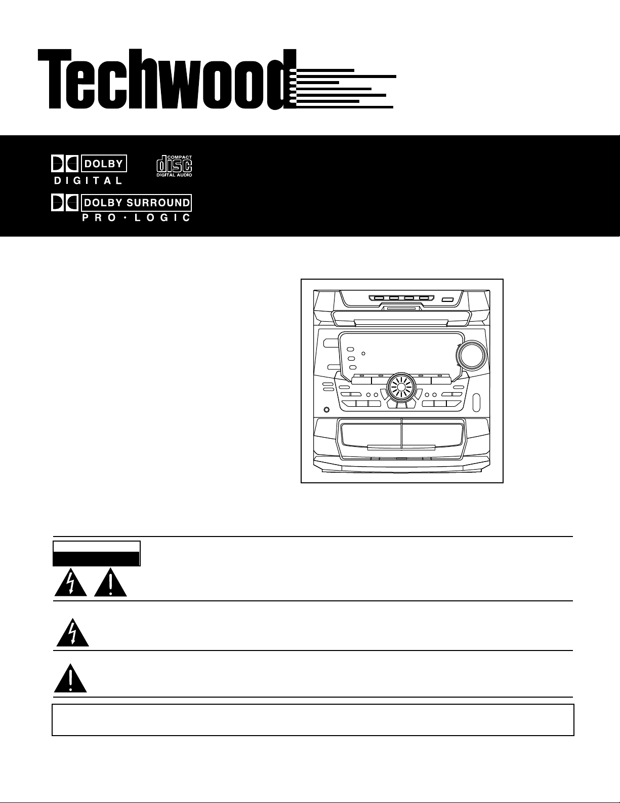
COMPACT DISC MUSIC SYSTEM
OWNER’S MANUAL
CAUTION
RISK OF ELECTRIC SHOCK
CAUTION: TO REDUCE THE RISK OF ELECTRIC SHOCK, DO NOT REMOVE COVER (OR
BACK). NO USER-SERVICEABLE PARTS INSIDE. REFER SERVICING TO QUALIFIED
SERVICE PERSONNEL.
The lightning flash with arrowhead symbol, within an equilateral triangle, is intended to alert the user to the
presence of uninsulated “dangerous voltage” within the product’s enclosure that may be of sufficient
magnitude to constitute a risk of electric shock to persons.
The exclamation point within an equilateral triangle is intended to alert the user to the presence of
important operating and maintenance (servicing) instructions in the literature accompanying the
Appliance.
WARNING: TO PREVENT FIRE OR SHOCK HAZARD, DO NOT EXPOSE
THIS APPLIANCE TO RAIN OR MOISTURE.
DO NOT OPEN
P/N: 3828RCD015A
Page 2
IMPORTANT SAFETY INSTRUCTIONS
CAUTION: "Note to CATV system installer:
> Read all of these Instructions. This reminder is provided to call the CATV system installer’s
> Save these Instructions for later use. attention to Section 820-40 of the NEC which provides guidelines
> Follow all Warnings and Instructions marked on the audio for proper grounding and, in particular, specifies that the cable
equipment. ground shall be connected to the grounding system of the building,
1) Read Instructions — All the safety and operating instructions
should be read before the product is operated.
2) Retain Instructions — The safety and operating instructions
should be retained for future reference.
3) Heed Warnings — All warnings on the product and in the
operating instructions should be adhered to.
4) Follow Instructions — All operating and use instructions
should be followed.
5) Cleaning — Unplug this product from the wall outlet before
cleaning. Do not use liquid cleaners or aerosol cleaners. Use a
damp cloth for cleaning.
6) Attachments — Do not use attachments not recommended by
the product manufacturer as they may cause hazards.
7) Water and Moisture — Do not use this product near water _ for
example, near a bath tub, wash bowl, kitchen sink, or laundry tub; in
a wet basement; or near a swimming pool; and the like.
8) Accessories — Do not place this product on an unstable cart,
stand, tripod, bracket, or table. The product may fall, causing
serious injury to a child or adult, and serious damage to the product.
Use only with a cart, stand, tripod, bracket, or table recommended
by the manufacturer, or sold with the product. Any mounting of the
product should follow the manufacturer’s instructions, and should 15) Lightning — For added protection for this product during a
use a mounting accessory recommended by the manufacturer. lightning storm, or when it is left unattended and unused for long
9) A product and cart combination should be moved with care. periods of time, unplug it from the wall outlet and disconnect the
Quick stops, excessive force, and uneven surfaces may cause the antenna or cable system. This will prevent damage to the product
product and cart combination to overturn. due to lightning and power-line surges.
10) Ventilation — Slots and openings in the cabinet are provided or electric shock.
for ventilation and to ensure reliable operation of the product and to 18) Object and Liquid Entry — Never push objects of any kind
protect it from overheating, and these openings must not be into this product through openings as they may touch dangerous
blocked or covered. The openings should never be blocked by voltage points or short-out parts that could result in a fire or electric
placing the product on a bed, sofa, rug, or other similar surface. shock. Never spill liquid of any kind on the product.
This product should not be placed in a built-in installation such as a 19) Servicing — Do not attempt to service this product yourself as
bookcase or rack unless proper ventilation is provided or the opening or removing covers may expose you to dangerous voltage
manufacturer’s instructions have been adhered to. or other hazards. Refer all servicing to qualified service personnel.
11) Power Sources — This product should be operated only from 20) Damage Requiring Service — Unplug this product from the
the type of power source indicated on the marking label. If you are wall outlet and refer servicing to qualified service personnel under
not sure of the type of power supply to your home, consult your the following conditions:
product dealer or local power company. For products intended to a) when the power-supply cord or plug is damaged.
operate from battery power, or other sources, refer to the operating b) if liquid has been spilled, or objects have fallen into the product.
instructions. c) if the product has been exposed to rain or water.
12) Grounding or Polarization — This product may be equipped d) if the product does not operate normally by following the
with a polarized alternating-current line plug (a plug having one operating instructions. Adjust only those controls that are covered
blade wider than the other). This plug will fit into the power outlet by the operating instructions as an improper adjustment of other
only one way. This is a safety feature. If you are unable to insert the controls may result in damage and will often require extensive work
plug fully into the outlet, try reversing the plug. If the plug should by a qualified technician to restore the product to its normal
still fail to fit, contact your electrician to replace your obsolete outlet. operation.
Do not defeat the safety purpose of the polarized plug. e) if the product has been dropped or damaged in any way.
13) Power-Cord Protection — Power-supply cords should be f ) when the product exhibits a distinct change in performance
routed so that they are not likely to be walked on or pinched by this indicates a need for service.
items placed upon or against them, paying particular attention to 21) Replacement Parts — When replacement parts are required,
cords at plugs, convenience receptacles, and the point where they be sure the service technician has used replacement parts specified
exit from the product. by the manufacturer or have the same characteristics as the original
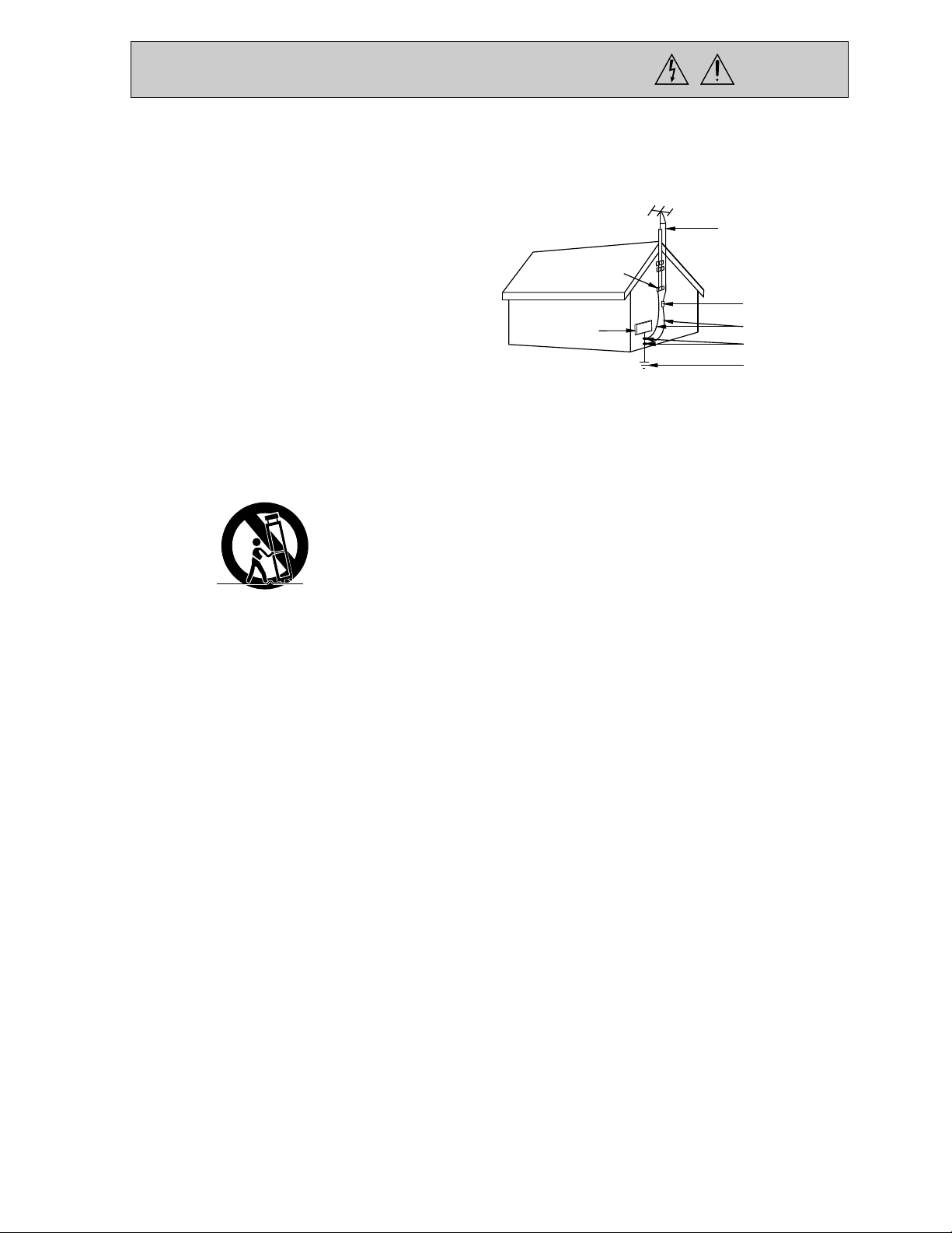
14) Outdoor Antenna Grounding — If an outside antenna or part. Unauthorized substitutions may result in fire, electric shock, or
cable system is connected to the product, be sure the antenna or other hazards.
cable system is grounded so as to provide some protection against 22) Safety Check — Upon completion of any service or repairs to
voltage surges and built-up static charges. Article 810 of the this product, ask the service technician to perform safety checks to
National Electrical Code, ANSI/NFPA 70, provides information with determine that the product is in proper operating condition.
regard to proper grounding of the mast and supporting structure, 23) Wall or Ceiling Mounting — The product should be mounted
grounding of the lead-in wire to an antenna discharge unit, size of to a wall or ceiling only as recommended by the manufacturer.
grounding conductors, location of antenna-discharge unit, 24) Heat — The product should be situated away from heat sources
connection to grounding electrodes, and requirements for the such as radiators, heat registers, stoves, or other products
grounding electrode. (including amplifiers) that produce heat.
as close to the point of cable entry as practical.”
ANTENNA
LEAD IN
WIRE
GROUND
CLAMP
ANTENNA
DISCHARGE UNIT
(NEC SECTION 810-20)
ELECTRIC
SERVICE
EQUIPMENT
NEC-NATIONAL ELECTRICAL CODE
16) Power Lines — An outside antenna system should not be
located in the vicinity of overhead power lines or other electric light
or power circuits, or where it can fall into such power lines or
circuits. When installing an outside antenna system, extreme care
should be taken to keep from touching such power lines or circuits
as contact with them might be fatal.
17) Overloading — Do not overload wall outlets, extension cords,
or integral convenience receptacles as this can result in risk of fire
GROUNDING CONDUCTORS
(NEC SECTION 810-21)
GROUND CLAMPS
POWER SERVICE GROUNDING
ELECTRODE SYSTEM
(NEC ART 250, PART H)
1
Page 3

CONTENTS
INTRODUCTION.............................................................................3-4
SPEAKER CONNECTION AND SET-UP......................................................5
AM & FM ANTENNA CONNECTIONS............................................................6
TELEVISION CONNECTION..........................................................................6
VCR CONNECTION.........................................................................................7
DVD CONNECTION.........................................................................................8
DIGITAL SATELLITE & CD RECORDER CONNECTION..............................9
SOUND ADJUSTMENT.............................................................................10-11
SURROUND EFFECTS............................................................................12-14
ADJUSTING CENTER AND REAR CHANNELS...........................................14
VIDEO OPERATIONS....................................................................................15
RADIO FUNCTIONS......................................................................................16
CD PLAYBACK.........................................................................................17-18
TAPE PLAYBACK.........................................................................................19
TAPE RECORDING.................................................................................19-20
CLOCK SETTING..........................................................................................21
SLEEP TIMER................................................................................................21
FUNCTION DISPLAY......................................................................................22
FRONT VIEW CONTROLS.............................................................................23
BACK VIEW INPUTS AND OUTPUTS...........................................................24
REMOTE CONTROL......................................................................................25
WARRANTY INFORMATION..........................................................................26
2
Page 4
INTRODUCTION
Important
Read this section before setting up or operating your new music system
The Techwood DD81 music system is a “state-of-the-art” digital home theater music system. It is equipped
with built-in, Dolby Digital Surround Sound, and is ready for the addition of digital audio/video components
such as DVD, DSS (digital satellite) and HDTV (high definition TV). This section describes some of the
features and Important things you need to know before proceeding with set-up or operation.
The DD81 is equipped with three built-in music sources that can be enjoyed by simply pressing one of the
corresponding function buttons on the front panel or remote control after initial set-up has been completed.
Tuner Plays AM and FM Stereo radio broadcasts
CD Plays music CD’s
Tape Plays and records cassette tapes
You can also connect optional audio/video components to the DD81 and create a true “Home Theater”
experience in your home. This allows the audio sound from the video components to play through the
DD81 music system. You can connect up to three of the following video components:
TV/AUX Television (regular or HDTV), Cable or Satellite Boxes
DVD Digital video disc player
VCR Video cassette recorder/player
To enjoy “Home Theater” surround sound, the Techwood DD81 is equipped with three different types of
Dolby Surround Sound plus, two simulated surround modes. The type of surround sound used to create
your “Home Theater” experience will depend on the video component being played, the type of audio
connection (analog or digital) made to the rear of the DD81 jack panel and the source material being
played. To enjoy true Dolby Surround Sound, the source material must be recorded or broadcast in either
Dolby Pro Logic or Dolby Digital Surround Sound. Source material recorded or
broadcast in stereo, such as radio broadcasts, CD’s, cassette tapes or TV programs can be played using
the Hall or Theater Simulated surround sound modes.
Surround Sound Modes
1) Hall (simulated)
2) Theater (simulated)
3) Dolby 3 Stereo
4) Dolby Pro Logic
5) Dolby Digital (Digital connection and Dolby Digital source required)
The first four types of surround sound will operate when using an analog, stereo audio signal from the tuner,
CD, cassette, TV, VCR, cable or satellite box.
The fifth type, Dolby Digital, will only operate when a digital component such as a DVD player, Digital Cable
Box, Digital Satellite (DSS) or HDTV is connected to one of the three digital audio inputs on the rear of the
DD81 and when a program or disc encoded in Dolby Digital Surround Sound is played.
IMPORTANT: Dolby Digital Surround Sound will not operate with an analog audio signal from the
tuner, CD, cassette, standard TV, VCR or cable box.
Since the DD81 is ready for the addition of digital audio/video components such as a DVD player, High
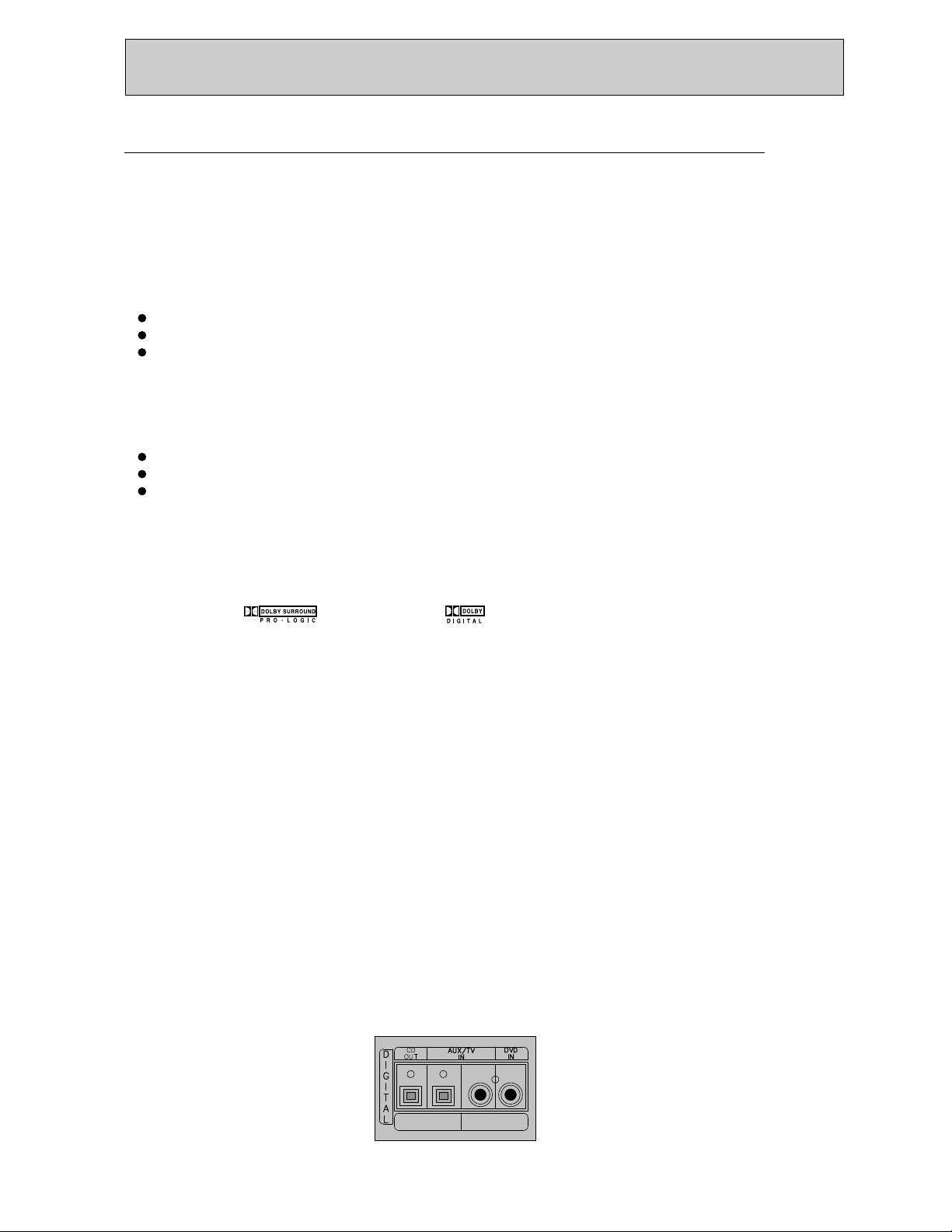
Definition TV (HDTV) or Digital Cable or Satellite Box, there are digital audio input jacks on the rear of
the unit. Digital audio inputs are included for the AUX/TV and DVD functions. This allows you to connect
up to two digital audio/video components – one to the AUX/TV function and another to the DVD function.
OPTICAL
AUDIO
COAXIAL
AUDIO
3
Page 5

INTRODUCTION
There is also a Digital Input selector on the front panel and remote control. If you are connecting
any audio/video components to the AUX/TV or DVD inputs, during the initial set-up and before
operating the unit, you must select the type of audio input signal used for each component.
STEREO DIRECTSTEREO DIRECT
DIGITAL INPUTDIGITAL INPUT SURROUND MODESURROUND MODE
BASSBASS TREBLETREBLE BALANCEBALANCE
MODE/RIFMODE/RIF REC/PAUSEREC/PAUSE
Use the Digital Input selector on the front panel or on the remote control to select between
analog and digital inputs. This must be done when using the AUX/TV and/or DVD functions
on the DD81. Once the input signal is set for each of these functions, the DD81 will remember
the input type for all future uses. Specific instructions for connecting digital audio/video
components to the DD81 are included below. It is recommended you read these instructions
before starting set-up.
Digital audio input jacks for connecting digital audio/video components
There are three digital input jacks and one digital output jack on the rear of the DD81. To enjoy
the built-in Dolby Digital Surround Sound feature, you must use a digital connection when
connecting a digital audio/video component such as a DVD player or digital cable box.
To connect a DVD player, use a single coaxial cable with RCA type jacks on both ends (available
at your local electronics store). Connect one end to the Digital Coaxial audio output on the DVD
player and the other end to the Digital Coaxial audio input on the rear of the DD81 (see page 8 for
connection diagram).
To connect a digital TV (HDTV), cable or satellite box, use a coaxial or optical audio cable (available
at your local electronics store). Connect one end to the Digital audio output on the TV/cable/satellite
box and the other end to the Digital audio input marked TV/AUX on the rear of the DD81.
(Note, some digital cable and satellite boxes do not have digital audio outputs. In this case, you
should connect the box to the DD81 using a standard analog audio cable with dual RCA type jacks
on each end. Connect one end to the two analog audio output jacks on the rear of the box and the
other end to the TV/AUX analog audio input jacks on the rear of the DD81(see pg. 9 for connection
diagram).
Digital Input Selector
If you connect any audio/video component to the AUX/TV or DVD audio inputs on the rear of the
DD81 (ie: TV, DVD, cable/satellite box), you must select the type of audio signal used for each
component connected. This must be done during initial set-up and before operating the DD81.
Using the Digital Input selector on the front panel or remote control, select the appropriate input
type used as follows:
Function Select Audio Input Signal Used
AUX/TV Analog – Optical – Coaxial
DVD Analog - Coaxial
After this first-time setting, the DD81 will memorize the type of audio input selected for all future uses.
Important: If you connect audio/video components to the AUX/TV or DVD functions of the DD81 and
after initial set-up you cannot hear audio sound, check which type of audio input has been selected.
If the audio input selected does not match the type of audio input actually used, you will not hear any
sound. Press the Digital Input Selector button one time to see which input has been selected. With
the input still illuminated in the display, press again to change the input.
If you have any questions about operating the DD81 home theater music system, call the
Techwood product support center at 888-440-3465, Monday to Friday, 8AM – 4PM CST.
4
Page 6
SPEAKER CONNECTIONS AND SET-UP
Speaker connection
Connect all speakers as illustrated below.
IMPORTANT NOTE: Use speakers that are
rated 8 ohms or higher and make sure that the
speaker polarity is correct (Red wires to Red
terminals Black wires to Black terminals).
Front Speaker
(Left)
L
E
F
T
R
I
G
H
T
Rear Speaker
(Left)
L
R
SPEAKER
L
R
Front Speaker
(Right)
Rear Speaker
(Right)
Speaker Set-up
IMPORTANT NOTE: Before operating the system
you must first set the speaker configuration by
using the following procedures.
1. Press the SPEAKER SETUP button to enter the
speaker setup mode. “SUBW YES(or NO)” appears
on the display. Note: If a powered subwoofer is
used select “SUBW YES”. If no powered subwoofer
is used select “SUBW NO”.
2. Use the PRESET DOWN/UP button or MULTI JOG
to select “SUBW YES” or “SUBW NO”. Press the
CLEAR/SET button to confirm it (or use the
ADJUST +/- buttons and SET button on the remote
Control).
3. Continue the speaker set-up procedure for center,
front and rear speakers as described below.
• CENTER SPEAKER Mode
- LARGE : Use this mode with a large center
speaker. The center channel’s output is
full range.
- SMALL : Use this mode with a small center
speaker.
- NONE : Use this mode if there is no center
speaker. The center channel signal will
be divided between the front L and R
Speakers.
Center Speaker
Speaker Positioning
The installation position of speakers differ according
to the size and acoustics of the listening room. While
actually listening to a program source, try various
speaker positions to determine which layout provides
the best surround effect.
1 3 2
4
6
5
1. Front Left Speaker
2. Front Right Speaker
3. Center Speaker
4. Rear Left Speaker (Not magnetically shielded)
5. Rear Right Speaker (Not magnetically shielded)
6. Viewing/Listening position. The optimum listening
position should be in the middle of all of
the speakers.
Connection of Optional Subwoofer
An RCA type jack marked "SUBWOOFER PRE
OUTPUT" is provided on the back of the unit for
connecting an optional powered Subwoofer.
• Subwoofer pre out signals are not amplified.
• If a speaker is connected directly to the PRE
OUTPUT jack without a built in amplifier, no
sound comes from the speaker.
• Subwoofer speakers are optional and are not
required.
• FRONT SPEAKER Mode
- LARGE : Choose if full range floor standing or
bookshelf front speakers are used.
- SMALL : Choose if small satellite front speakers are
used. When using small speakers, it is
recommended that a powered Subwoofer
be added to play low frequencies.
• REAR(SURR) SPEAKER Mode
- SMALL : Use this mode with a small rear
(surround) speaker.
- NONE : Use this mode if there is no rear
(surround) speaker. The rear channel signal
will be divided between the front L and R
speakers.
5
Page 7
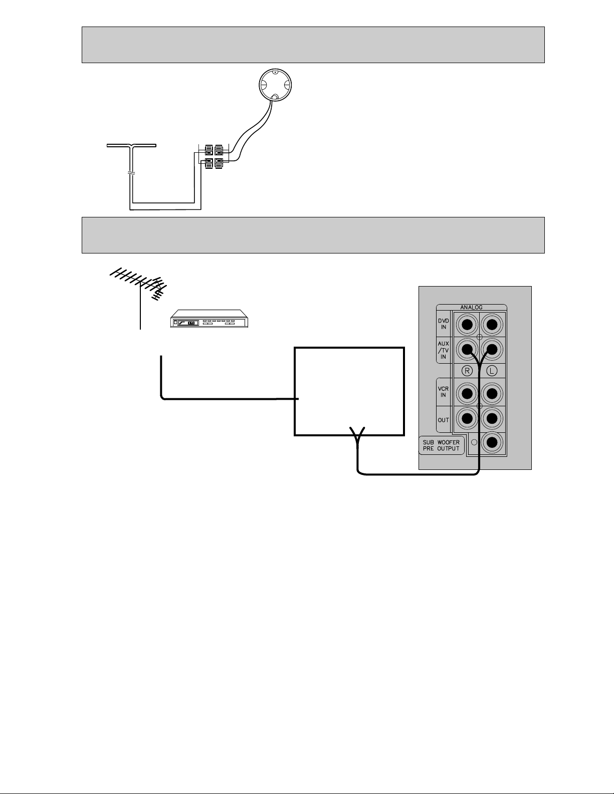
AM & FM ANTENNA CONNECTIONS
FM Antenna
AM loop
Antenna
Connect the supplied FM dipole antenna (shaped like
a “T”) to the ANTENNA terminals marked “FM” and
“GND” on the rear of the unit and position it for
FM indoor
dipole antenna
Position
it for the
best
reception
GND
FM
AM
best reception.
AM Antenna
To receive AM radio broadcasts, you must connect
the supplied AM loop antenna to the terminals
marked “AM” on the rear of the unit. Position it for
best reception.
TV CONNECTIONS (ANALOG)
ANTENNA OR CABLE BOXANTENNA OR CABLE BOX
HOW TO PLAY THE TELEVISION SOUND
THROUGH THE STEREO SYSTEM
NOTE: The following instructions only apply
if your television has variable audio outputs or
has been set to operate in variable output mode.
If your TV has fixed audio outputs, the volume is
controlled by the DD81.
After making connections as shown above follow
these instructions to obtain the best performance.
1. Set the volume control on the stereo at about 15
(1/2 of maximum volume).
2. Set the SURROUND MODE to the desired
pattern-ANALOG STEREO(STEREO DIRECT),
HALL, THEATER, PRO LOGIC or 3 STEREO.
TELEVISIONTELEVISION
ANT IN
AUDIO OUT
5. Select the channel desired and adjust the
listening level using the volume control on the
Television.
Do not adjust the listening level with the controls
on the stereo. lf your television is equipped with a
hand held remote control, you can use the remote
control to operate the television including
adjustment of volume.
6. When you have finished watching TV, be certain
to turn off both the television and stereo.
Remember to read the television operating manual
so you can enjoy all of the features of your
television. lf you have followed these instructions
and the system is not operating properly, contact
the dealer where you obtained the system before
calling a warranty center.
3. Turn the television on by depressing the power
Button.
4. Press AUX(TV)/VCR/DVD button repeatedly until
the “AUX/TV” appears on the display.
Important: Most malfunctions are the result of
improper installation or operating procedure and are
not covered under the stereo or television
warranties.
6
Page 8
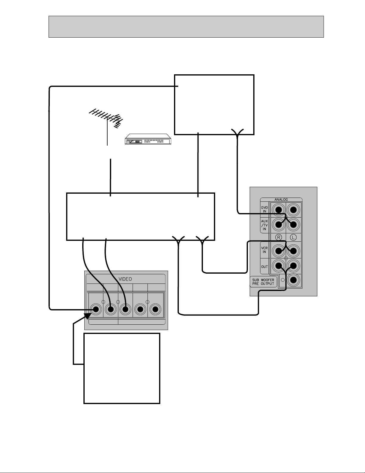
VCR & TV CONNECTIONS (ANALOG)
TELEVISIONTELEVISION
(yellow)
VIDEO
IN
AUDIO
ANT IN
ANTENNA OR CABLE BOXANTENNA OR CABLE BOX
VCRVCR
OUT
ANT IN
(yellow)
VIDEO
(yellow)
VIDEO
IN
OUT
NOTE: All VIDEO IN/OUT
jacks are yellow in color.
MONITOR
RECORD
OUT
OUT IN
NOTE: When connecting
more than one video
component to the DD81
(ie: VCR and DVD player)
it is easier to use the yellow
VIDEO MONITOR OUT jack.
This allows all video signals
(VCR and DVD) to be sent
through the DD81 to the
TV using just one RCA
video input on the TV.
VCRINAUX/TVINDVD
OUT
TV OUT
AUDIO
IN
IN
AUDIO
OUT
7
Page 9
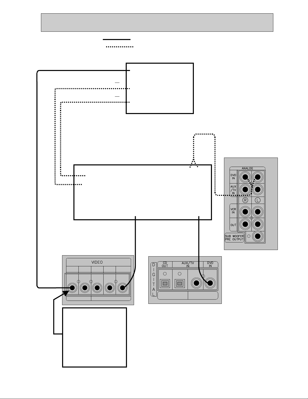
DVD & TV CONNECTIONS (DIGITAL)
NOTE: Solid lines = suggested method of connection
Dotted lines = alternate method of connection
TELEVISIONTELEVISION
(yellow)
VIDEO
or
or
NOTE: If your TV
and DVD changer
have s-video or
component video
jacks, you can
connect the video
directly to your
TV.
DVD CHANGERDVD CHANGER
IN
COMPONENT VIDEO
IN
S-VIDEO
IN
S-VIDEO
OUT
COMPONENT VIDEO
OUT
COMPOSITE
NOTE: All VIDEO IN/OUT
jacks are yellow in color.
RECORD
MONITOR
OUT
OUT IN
NOTE: When connecting
more than one video
component to the DD81
(ie: VCR and DVD player)
it is easier to use the yellow
VIDEO MONITOR OUT jack.
This allows all video signals
(VCR and DVD) to be sent
through the DD81 to the
TV using just one RCA
video input on the TV.
VCRINAUX/TVINDVD
OUT
IN
(yellow)
VIDEO
OUT
ANALOG
AUDIO
OUT
(orange)
COAXIAL
AUDIO
OUT
OPTICAL
AUDIO
NOTE: All COAXIAL AUDIO
IN jacks are orange in color.
DIGITAL
COAXIAL
AUDIO
8
Page 10

DIGITAL SATELLITE, TV & CD RECORDER CONNECTIONS
NOTE: Solid lines = suggested method of connection
Dotted lines = alternate method of connection
TELEVISIONTELEVISION
(yellow)
VIDEO
IN
COMPONENT VIDEO
IN
S-VIDEO
IN
(yellow)
COMPOSITE
VIDEO
OUT
DIGITAL
OPTICAL
AUDIO
OUT
(orange)
COAXIAL
or
AUDIO
OUT
NOTE: If your TV
and satellite box
have s-video or
component video
jacks, you can
connect the video
directly to your
TV.
S-VIDEO
COMPONENT
or
or
DIGITAL SATELLITE OR CABLE BOX DIGITAL SATELLITE OR CABLE BOX
OUT
VIDEO
OUT
NOTE: All VIDEO IN/OUT
jacks are yellow in color.
RECORD
MONITOR
OUT
OUT IN
NOTE: When connecting
more than one video
component to the DD81
(ie: VCR and DVD player)
it is easier to use the yellow
VIDEO MONITOR OUT jack.
This allows all video signals
(VCR and DVD) to be sent
through the DD81 to the
TV using just one RCA
video input on the TV.
VCRINAUX/TVINDVD
OUT
IN
OPTICAL
AUDIO
NOTE: All COAXIAL AUDIO
IN jacks are orange in color.
COAXIAL
AUDIO
DIGITAL
CD RECORDERCD RECORDER
AUDIO
IN
NOTE: You may record audio to a CD
by connecting an optical audio cable
from the CD out on the DD81 to an
optical audio in of a CD recorder.
9
Page 11

SOUND ADJUSTMENT
BASS
HEADPHONE
JACK
TREBLE
BALANCE
DISC 1DISC 1
DISC 2DISC 2 DISC 3DISC 3 DISC SKIPDISC SKIP
POWERPOWER
POWER SAVINGPOWER SAVING
ON/STANDBYON/STANDBY
SPEAKER SETUPSPEAKER SETUP
DEMODEMO
PHONESPHONES
CLOCKCLOCK
TIMERTIMER
LEVEL SELECTLEVEL SELECT
TEST TONETEST TONE
DIGITAL INPUTDIGITAL INPUT SURROUND MODESURROUND MODE
BASSBASS TREBLETREBLE BALANCEBALANCE
OPENOPEN
TAPE ATAPE A
PLAYBACKPLAYBACK
CDCD TAPE A/BTAPE A/B AUX(TV)/VCR/DVDAUX(TV)/VCR/DVD
TUNER/BANDTUNER/BAND
TUNINGTUNING
DOWNDOWN
MODE/RIFMODE/RIF REC/PAUSEREC/PAUSE CD PAUSECD PAUSECD SYNC.CD SYNC.
PRESETPRESET
DOWNDOWN
Adjust the
BASS, TREBLE,
BALANCE
VOLUME
OO
PRESETPRESET
CLEAR/SETCLEAR/SET
UPUP
PLAYPLAY REC/PLAYREC/PLAY
Volume Adjustment
OPEN/CLOSEOPEN/CLOSE
Turn VOLUME CONTROL clockwise to increase the
sound level or counterclockwise to decrease it.
(or press VOLUME button on the remote
control.)
VOLUMEVOLUME
CONTROLCONTROL
UPUP
DOWNDOWN
TUNINGTUNING
UPUP
PROGRAM/PROGRAM/
MEMOMEMO..
HIGH-DUBBING-NORMALHIGH-DUBBING-NORMAL
REPEATREPEAT RANDOMRANDOM
SYNCHRO DUBBINGSYNCHRO DUBBING
COUNTER RESETCOUNTER RESET
OPENOPEN
TAPE BTAPE B
Bass Adjustment
This function will raise or lower the level of bass
heard on the front left and right speakers.
Press the BASS button and adjust the bass level by
using the PRESET UP/DOWN buttons or MULTI
JOG and confirm it by pressing the CLEAR / SET( )
button.
Treble Adjustment
This function will raise or lower the level of treble
heard on the front left and right speakers.
Press the TREBLE button and adjust the treble level
by using the PRESET UP/DOWN buttons or MULTI
JOG and confirm it by pressing the CLEAR/SET( )
button.
Balance Adjustment
The BALANCE button balances the volume level of
front left and right speakers.
Press, the BALANCE button and adjust
the volume of the front left or right speaker with the
PRESET DOWN/UP buttons or MULTI JOG. Balance
adjustments are from “BAL R 01” to “BAL R 10” and
“BAL L 01” to “BAL L 10”.
If the number of the L increases, the front left
speaker’s volume increases and the front right
speaker’s volume decreases. If the number of
the R increases, the front right speaker’s volume
increases and the front left speaker’ s volume
decreases.
To confirm the balance adjustment press the
CLEAR/SET( )button.
10
NOTE: The balance function will not work when
the “stereo direct” button is on.
Headphone Listening
Connect a stereo headphone(not supplied) plug into
the headphone jack.
The speakers are automatically disconnected when
using headphones.
Volume Mute
Press the Mute button on the remote control to mute
your unit. The indicator appears on the display.
Press again to resume playback.
Page 12

SOUND ADJUSTMENT
DISC 1DISC 1
POWERPOWER
ON/STANDBYON/STANDBY
DEMODEMO
CLOCKCLOCK
STEREO DIRECTSTEREO DIRECT
PHONESPHONES
STEREO
STEREO
DIRECT
DIRECT
button
button
SURROUND MODE
SURROUND MODE
button
button
DIGITAL INPUT
DIGITAL INPUT
button
button
SURROUND MODE
SURROUND MODE
button
button
POWER SAVINGPOWER SAVING
SPEAKER SETUPSPEAKER SETUP
LEVEL SELECTLEVEL SELECT
TEST TONETEST TONE
DIGITAL INPUTDIGITAL INPUT SURROUND MODESURROUND MODE
BASSBASS TREBLETREBLE BALANCEBALANCE
OPENOPEN
TAPE ATAPE A
PLAYBACKPLAYBACK
CDCD TAPE A/BTAPE A/B AUX(TV)/VCR/DVDAUX(TV)/VCR/DVD
TUNER/BANDTUNER/BAND
TUNINGTUNING
DOWNDOWN
MODE/RIFMODE/RIFREC/PAUSEREC/PAUSE CD PAUSECD PAUSE CD SYNC.CD SYNC.
SURROUND
SURROUND
DIGITAL
INPUT
STEREO
DIRECT
DISC 2DISC 2 DISC 3DISC 3 DISC SKIPDISC SKIP
PRESETPRESET
CLEAR/SETCLEAR/SET
DOWNDOWN
PLAYPLAY REC/PLAYREC/PLAY
R.I.F.
R.I.F.
button
button
MODE
TEST
TONE
PRESETPRESET
UPUP
OPEN/CLOSEOPEN/CLOSE
VOLUMEVOLUME
CONTROLCONTROL
UPUP
DOWNDOWN
MEMOMEMO..
HIGH-DUBBING-NORMALHIGH-DUBBING-NORMAL
REPEATREPEAT RANDOMRANDOM
SYNCHRO DUBBINGSYNCHRO DUBBING
COUNTER RESETCOUNTER RESET
OPENOPEN
TAPE BTAPE B
TUNINGTUNING
UPUP
OO
PROGRAM/PROGRAM/
IMPORTANT NOTE: The first time you operate
the unit with an optional DVD player or television
connected to the DD81, you must select and set
the type of audio input used, digital or analog, for
each device using the DIGITAL INPUT button.
After this first-time setting,the unit will remember
the input and you will not have to select the input
source again. Three digital audio inputs are included
on the unit labeled DVD IN COAXIAL, AUX/TV IN
COAXIAL AND AUX/TV IN OPTICAL. To obtain
the best sound, connect a DVD player to the DVD
coaxial digital input with a coaxial cable.
MODE/RIF(Radio Interference Filter)
If the FM signal is too weak to receive stereo FM
without interference, set the FM mode to mono.
If the AM signal is too weak to receive without
interference, you can press the R.I.F. button to
reduce the static that is heard.
SURROUND MODE Button
Use the Surround mode button to select the type of sound
desired – surround or stereo.Each time you press the
surround mode button, the type of surround sound will
change. When playing stereo analog audio sources such as
the tuner, tape, CD, television or VCR you may select from:
PRO-LOGIC 3 STEREO ANALOG STEREO
HALL THEATER
The PRO-LOGIC and 3 STEREO surround modes, require
an audio source that is recorded or broadcast in Dolby
Surround Sound . Most videos and many
television programs are recorded in Dolby Surround.
Standard stereo recordings and broadcasts should be
played in ANALOG STEREO, THEATER or HALL modes.
Note: you can play standard stereo audio signals from the
tuner, tape, CD, VCR or TV in PRO-LOGIC or 3 STEREO
mode. However, the rear channel output levels may sound
low and fade in and out. Also, mono (non-stereo) audio
sources, like AM radio stations, will not play in surround
sound. Surround sound requires a stereo audio source.
When operating the DD81 in DIGITAL mode with an
optional DVD player or Digital cable / satellite box
connected and when the audio program source is in Dolby
Digital Surround Sound , you may select DIGITAL
surround sound using the surround mode button. This
surround option is only available when a DVD player, HDTV
or Digital cable / satellite box is connected to the DVD or
AUX/TV digital audio input jacks on the rear of the DD81
and the audio source being played is recorded or broadcast
in Dolby Digital Surround Sound.
STEREO DIRECT MODE
Selecting the STEREO DIRECT button will bypass the
current surround mode setting allowing you to listen in 2
channel stereo. Turning the STEREO DIRECT button off
will return the unit to the current surround mode setting.
SURROUND OFF (STEREO) Position
Press SURROUND MODE button repeatedly to switch from
surround mode to stereo mode, until “ANALOG STEREO ”
appears in the display.
When operating the unit in Dolby Digital mode, this button
operates as down mix (2 channel) function and the “DOWN
MIX” indicator will light up.
DIGITAL INPUT (SELECT) Button
(Refer to important note to the left)
Press this button to select the type of input signal for the
AUX/TV and DVD functions.
• When the DVD function is selected.
ANALOG DIGITAL (coaxial)
• When Aux/TV selected.
ANALOG DIGITAL (optical) DIGITAL (coaxial)
11
Page 13

SURROUND EFFECTS
SURROUND SOUND EFFECTS DOLBY PRO LOGIC Surround
The DD81 can play five different types of surround Dolby Pro Logic is a surround format that uses an
sound depending on the program source and the analog audio signal. It is the audio format used for
type of audio connection. The following section most video cassette tapes and many television
describes the different types of surround sound. broadcasts over-the-air and through cable and
DOLBY DIGITAL Surround
Dolby Digital is a surround sound format that uses
a digital audio signal. It is the audio format used for
most Digital Video Discs (DVD) and for digital high
definition television broadcasts over-the-air and
through digital cable and satellite boxes. Federal
law requires all television broadcasts to be made in
high definition format by 2006. Therefore, Dolby
Digital will become the dominant surround sound
format in the future. This DD81 music system is
ready when you are for adding digital TV and other
digital audio/video components.
Dolby Digital recordings and broadcasts have 6
channels of sound for the most authentic theater
experience. These six channels are sometimes
referred to as 5.1 channels – five full-range and
one low frequency effects (LFE) channel. The LFE
channel has special low frequencies that can be
played back through an optional powered
subwoofer. This creates frequencies so low, you
can “feel” them. The digital signals used in Dolby
Digital provide the most accurate sound
reproduction available.
1) Front left channel
2) Front right channel
3) Center channel
4) Left rear surround channel
5) Right rear surround channel
6) Low frequency channel
satellite boxes. Although not normally used for
radio broadcasts and music on CD’s and cassette
tapes, the Dolby Pro Logic surround sound
function can be used for these sources when they
are broadcast or recorded in stereo. Dolby Pro
Logic requires a stereo audio signal to operate – it
does not work with mono audio signals.
Dolby Pro Logic offers 5 channels of sound:
1) Front left channel
2) Front right channel
3) Center channel
4) Rear channel (2 speakers)
The DD81 Dolby Pro Logic surround sound
function operates when:
An optional stereo television, Hi-Fi VCR or
DVD player is connected to the audio inputs
on the rear of the DD81.
The program source (tape, disc or broadcast)
is recorded in Dolby Pro Logic Surround
Sound .
And, the digital input selector is properly set
according to the connection made between
the component and the DD81.
The DD81 built-in, Dolby Digital surround sound
processor will only operate when:
An optional digital audio/video component
such as a DVD player, HDTV, digital cable
or digital satellite box is connected to
the DD81.
The optional component is connected to the
DVD or AUX/TV digital inputs on the rear of
the DD81.
The program source (disc or broadcast) is
recorded in Dolby Digital Surround
Sound .
And, the digital input selector is properly set
according to the type of audio connection
made between the component and the DD81.
12
(Continued on next page)
Page 14

SURROUND EFFECTS
HALL AND THEATER Surround 3 STEREO Surround
The Hall and Theater surround sound functions Dolby 3 Stereo surround sound uses analog or
use standard analog audio signals to create a digital audio signals to playback through three
simulated surround effect like found in a concert speakers. You do not require rear speakers.
hall or movie theater. Since some music, video
and television sources are recorded in stereo not 1) Front left channel
Dolby Surround Sound, they will not play properly 2) Front right channel
using the Dolby Digital or Dolby Pro Logic 3) Center channel
surround functions.
This allows you to enjoy a home theater surround
However, when listening to FM radio stations, sound experience without connecting rear
cassette tapes, CD’s or television broadcasts, channel speakers.
you can select the Hall or Theater functions to
create a surround sound effect. 3 Stereo can be used with both Dolby Digital or
Note: the broadcast or recording must be in Dolby Pro Logic audio sources.
stereo to use these surround functions – mono
audio sources cannot be used.
The Hall surround function simulates the feeling
of a concert hall. The normal left and right stereo
channel information is directed to the main
speakers. A reverberated surround sound is
created and directed to the center and rear
speakers.
The Theater surround function provides a three
dimensional experience like a movie theater. It
simulates an effect similar to Dolby Pro Logic
when playing source material that is recorded or
broadcast in stereo but not in Dolby Surround.
13
Page 15

SURROUND EFFECTS
Delay Time Setting Delay Time
In the surround modes, the sound is delayed from Press the SPEAKER SET-UP button to set the
the front to the rear speakers. The optimum delay delay time in the DOLBY DIGITAL/DOLBY PRO
time will depend on acoustic properties of the room LOGIC modes. Adjust the delay time for the center
and the distance of the listening area from the speakers. or rear speakers by using the:
It is recommended that you try different delay times 1. MULTIJOG/PRESET DOWN/UP on the system or
to obtain the best effect. The delay is digitally by using the ADJUST +/- buttons on the remote.
synthesized, for the highest sound quality with
minimum noise and distortion. 2. Then confirm it by pressing the CLEAR/SET button
on the system or by pressing the SET button on the
The delay time can be set independently for each remote control.
Surround mode with the current setting shown on
the display. Surround Mode Adjustable Range
DOLBY DIGITAL 0 ~ 15 ms in 1ms step (S-Delay)
0 ~ 5 ms in 1ms step (C-Delay)
DOLBY PRO LOGIC 15 ~ 30 ms in 1ms step (S-Delay)
ADJUSTING CENTER AND REAR CHANNELS
TEST TONE adjustment NOTE: Front left and right speaker levels are adjusted
When your system is in the Dolby Pro Logic, Dolby 3 by using the master volume control and balance
stereo, Dolby Digital, HALL or THEATER surround control. You can adjust the individual levels of the
sound mode the TEST TONE can be used to adjust center, rear left, rear right and subwoofer by using the
the volume levels for the center and rear channels. following procedure .
According to the position of the SURROUND MODE,
the test noise will be heard from each speaker for While the appropriate speaker’s test noise is
about 3 seconds in the following cycle. emitted, adjust the volume level by using the:
A test noise will travel ... Front Left speaker ... Center 1. MULTIJOG/PRESET DOWN/UP on the system or
speaker ... Front Right speaker ... Rear Right by usingthe ADJUST +/- buttons on the remote.
(Surround) speaker ... Rear Left (Surround) speaker
...Sub Woofer ... and continue to repeat until the 2. Then confirm it by pressing the CLEAR/SET button
Test Tone button is pressed again. on the system or by pressing the SET button on the
remote control.
As the test noise is being heard you may adjust the
speaker volume of the center, rear (surround) and NOTE:
subwoofer speakers to the level most suited to your This unit is manufactured under license from Dolby
listening area or preference. Laboratories.“Dolby”, “Pro Logic”, and the double-D
symbol are trademarks of Dolby Laboratories.
14
Page 16

VIDEO OPERATIONS
Playing Video Sources Recording with a Video Deck
Note : For playing video software using a certain Tape Dubbing (from VCR, AUX/TVto
Surround Effect function, refer to the VIDEO REC OUT)
SURROUND EFFECTS section.
Video Signals
Audio Signals
POWERPOWER
POWER SAVINGPOWER SAVING
ON/STANDBYON/STANDBY
SPEAKER SETUPSPEAKER SETUP
DEMODEMO
LEVEL SELECTLEVEL SELECT
TUNER/BANDTUNER/BAND
CLOCKCLOCK
TEST TONETEST TONE
TIMERTIMER
DIGITAL INPUTDIGITAL INPUTSURROUND MODESURROUND MODE
MODE/RIFMODE/RIF REC/PAUSEREC/PAUSE CD PAUSECD PAUSECD SYNC.CD SYNC.
BASSBASS TREBLETREBLE BALANCEBALANCE
PHONESPHONES
OPENOPEN
TAPE ATAPE A
PLAYBACKPLAYBACK
DISC 1DISC 1
DISC 2DISC 2 DISC 3DISC 3 DISC SKIPDISC SKIP
CDCD TAPE A/BTAPE A/B AUX(TV)/VCR/DVDAUX(TV)/VCR/DVD
TUNINGTUNING
TUNINGTUNING
DOWNDOWN
MM
UU
LL
TT
II
JJ
OO
GG
DD
II
AA
LL
CC
OO
NN
TT
RR
OO
LL
PRESETPRESET
PRESETPRESET
CLEAR/SETCLEAR/SET
DOWNDOWN
UPUP
PLAYPLAY REC/PLAYREC/PLAY
AUX/TV
VCR DVD
OPEN/CLOSEOPEN/CLOSE
VOLUMEVOLUME
CONTROLCONTROL
UPUP
DOWNDOWN
COUNTER RESETCOUNTER RESET
UPUP
HIGH-DUBBING-NORMALHIGH-DUBBING-NORMAL
PROGRAM/PROGRAM/
REPEATREPEAT RANDOMRANDOM
MEMOMEMO..
OPENOPEN
TAPE BTAPE B
SYNCHRO DUBBINGSYNCHRO DUBBING
Video Signals
Audio Signals
POWERPOWER
ON/STANDBYON/STANDBY
DEMODEMO
CLOCKCLOCK
TEST TONETEST TONE
TIMERTIMER
DIGITAL INPUTDIGITAL INPUTSURROUND MODESURROUND MODE
PHONESPHONES
TIMER
REC
VCR
AM
VCR
Recording
DISC 1DISC 1
POWER SAVINGPOWER SAVING
SPEAKER SETUPSPEAKER SETUP
LEVEL SELECTLEVEL SELECT
CDCD TAPE A/BTAPE A/B AUX(TV)/VCR/DVDAUX(TV)/VCR/DVD
TUNER/BANDTUNER/BAND
TUNINGTUNING
DOWNDOWN
MODE/RIFMODE/RIF REC/PAUSEREC/PAUSE CD PAUSECD PAUSECD SYNC.CD SYNC.
BASSBASS TREBLETREBLE BALANCEBALANCE
OPENOPEN
TAPE ATAPE A
PLAYBACKPLAYBACK
VCR
DISC 2DISC 2 DISC 3DISC 3 DISC SKIPDISC SKIP
OO
NN
TT
RR
OO
LL
PRESETPRESET
PRESETPRESET
CLEAR/SETCLEAR/SET
DOWNDOWN
PLAYPLAY REC/PLAYREC/PLAY
OPEN/CLOSEOPEN/CLOSE
VOLUMEVOLUME
CONTROLCONTROL
UPUP
DOWNDOWN
COUNTER RESETCOUNTER RESET
TUNINGTUNING
UPUP
HIGH-DUBBING-NORMALHIGH-DUBBING-NORMAL
MM
UU
LL
TT
II
JJ
OO
GG
DD
II
AA
LL
CC
PROGRAM/PROGRAM/
REPEATREPEAT RANDOMRANDOM
MEMOMEMO..
UPUP
OPENOPEN
TAPE BTAPE B
SYNCHRO DUBBINGSYNCHRO DUBBING
AUX/TV
1. Select the AUX/TV, VCR or DVD mode by
pressing the AUX(TV)/VCR/DVD.
Playback
FUNCTION select button repeatedly.
1.Press the AUX(TV)/VCR/DVD button repeatedly to
2. Play the component corresponding to the select the VIDEO source to be recorded.
FUNCTION selected.
2.Play back the source (AUX/TV or VCR).
3. The picture from the video source can be seen on
the TV and sound from the video source will be 3.Operate VCR for recording. Video/audio signals
heard from the speakers if the video device has from the selected VIDEO component (VCR or
been connected to the stereo system. AUX/TV) can be dubbed to VCR.
If video devices have been connected directly to
the television, additional steps may be required. Note :
When tape dubbing is performed, be sure to connect
the LINE OUT (analog audio output).
Note:
DVD’s are specially encoded by the manufacturer
to prevent recorded duplication.
15
Page 17

RADIO FUNCTIONS
Tuning Automatically
1. Turn on the power.
2. Press TUNER/BAND button repeatedly until the
desired band appears (AM or FM).
3. Press TUNING DOWN/UP( or ) button
for more than 0.5 seconds. The unit tunes in a
station automatically.
Tuning Manually
1. Turn on the power.
2. Press TUNER/BAND button repeatedly until the
desired band appears (AM or FM).
3. Press TUNING DOWN/UP( or ) button
briefly and repeatedly, until the desired station
appears.
Storing Stations
1. To clear any previously stored stations in memory
A. Press the PROGRAM/MEMO. button more than
1.5 seconds in TUNER mode so that CLEAR is
flashing in the display.
B. Press the CLEAR/SET( ) button again while
CLEAR is flashing in the display.
2. To memorize stations
A. Press the TUNER/BAND button to select
(AM or FM).
B. Press the TUNING DOWN/UP( or )
button to select a desired station.
C. Press the PROGRAM/MEMO. button. MEMORY
appears and preset number blinks.
D. Press the PROGRAM/MEMO. button again
while preset number is flashing.
E. Repeat step A to D to memorize up to 30 stations.
3. To replace or add a memorized station
A. Select a desired station.
B. Press the PROGRAM/MEMO. button.
While the preset number is flashing select a
desired channel number by using the
PRESET DOWN/UP button or MULTI JOG.
C. Press the PROGRAM/MEMO. button again
before channel number stops flashing.
4. To recall presets
Press and hold the PRESET DOWN/UP button until the
desired preset number appears or press it repeatedly.
16
Page 18

CD PLAYBACK
21
Number 1 disc Number 2 disc
Basic Operation
1. Press the CD FUNCTION button.
2. Press the CD OPEN/CLOSE button to open the
disc drawer.
3. Load disc (s) with the label side up.
Playing one or two discs
Place discs on trays 1 and 2.
Playing three discs
After placing two discs, press the DISC SKIP
button to rotate the trays. Place the next disc on
tray 3.
NOTICE
To load an 8cm(3 in.) disc, put it onto the inner
circle of the tray.
4. Press the CD OPEN/CLOSE button to close the
Disc drawer.
5. Press the CD PLAY( or on remote
control) button to start play.
Play begins with the disc on left side tray when
the disc drawer is closed . All the discs are
played once only.
During playback
A tray which has no disc is skipped and play
proceeds to the next tray. The indicator of the
skipped tray number goes out in the display.
To stop play
Press the STOP ( CLEAR/SET) button.
To pause
Press the CD PAUSE ( or ) button.
To resume play, press it again.
To skip discs
During play or in the stop mode, press the DISC SKIP
button.
During play
Play begins automatically after skipping.
In the stop mode
The changer skips to the next disc, but the player
remains stopped. Press the CD PLAY ( ) or ( )
button to play the next disc. Play begins and all the
discs are played once.
To play one disc only
Press one of the DISC DIRECT PLAY(DISC 1,2,3)
buttons to start play.
To remove discs
Press the CD OPEN/CLOSE button to open the disc
drawer. You can remove two discs. To remove
the disc on the back tray, press the DISC SKIP button
to rotate the disc tray.
Changing Discs During Play
Two discs can be changed while the other remaining
disc is played.
This operation is not applicable during programmed
play.
1. Press the CD OPEN/CLOSE button to open the
disc drawer.
2. Remove the discs and place other discs.
The disc placed on the left side tray will be played
next.
3. Press the CD OPEN/CLOSE button to close the
disc drawer.
NOTES
Do not tilt the unit with discs loaded. This may
dislodge the discs. Usage under these conditions
may damage the discs.
Do not place more than one compact disc on one
disc tray at the same time.
If, during CD play, the video image of a nearby
television is distorted, or if static is heard from a
nearby radio, move this unit further away from the
affected television or radio.
Searching for a Particular Point
in a Track
You can locate a particular point in a track during
play by listening to the sound playing at high-speed
or by observing the CD counter in the display.
To search back:
Press the button and release it at the
desired point.
To search forward:
Press the button and release it at the
desired point.
17
Page 19

CD PLAYBACK
Skipping to the Beginning of a Track
You can locate the beginning of any track on a disc.
To return to the beginning of the current or
previous track. Press the button once to return
to the beginning of the current track.
Press the button repeatedly to skip tracks
backward one by one.
To skip tracks
Press the button repeatedly to skip track(s)
forward one by one.
Random Play
All the tracks on all discs in the drawer can be
played randomly.
To play all tracks on all discs randomly
Press the RANDOM button to display RANDOM.
To cancel random play
Press the RANDOM button so that RANDOM in the
display goes out.
To skip tracks in the random play mode
When the button is pressed, the next track is
selected at random. The button functions only
to return to the beginning of the current track during
random play.
Repeat Play
To play one track repeatedly
Press the REPEAT button to display “REPEAT 1” and
press the PLAY/PAUSE button to start play.
To play one disc repeatedly
Press the REPEAT button until “REPEAT 1 DISC”
appears in the display and press PLAY/PAUSE
button to start play.
To play all tracks on all discs repeatedly
Press the REPEAT button until “REPEAT ALL DISC”
appears in the display and press the PLAY/PAUSE
button to start play.
To repeat a programmed sequence
Program the desired tracks, and press the REPEAT
button to display “REPEAT 1” or “REPEAT ALL DISC”.
To cancel repeat play
Press the REPEAT button so that “REPEAT” in the
display goes out.
NOTE:
During random play, you can play repeatedly an
entire disc (REPEAT 1 DISC) or all discs (REPEAT
ALL DISC).
During repeat one track play (REPEAT 1), if you
press the RANDOM button, the repeat play is
cancelled.
During the programmed play; you can play
one track(REPEAT 1) or all discs (REPEAT ALL
DISC)
During the repeat play of an entire disc; if you
press the programmed play button it will repeat
all of the discs in the CD drawer .
Programmed Play
The player has a memory function that allows play of
up to 20 tracks from three discs in any order.
1. Press the PROGRAM button in the stop mode.
2. Press DISC SKIP button to select a disc.
3. Press the or button to select the
tracks.
To select the 6th track, press the or button
repeatedly until track number “6” is displayed in the
display.
4. Press the PROGRAM button.
5. Repeat steps 2 to 4.
6. Press the PLAY/PAUSE button to start play.
To check the programmed contents
Each time the PROGRAM button is pressed in the
stop mode, a disc number, a track number and a
program number will be displayed.
To clear the programmed contents
Press the PROGRAM button during stop and then
press the CLEAR/SET button or,
Turn off the power or,
Press the CD OPEN/CLOSE button.
To add tracks to the program
1. Press the PROGRAM button repeatedly until
00 is displayed.
2. Select the desired track on the disc with DISC
SKIP button or .
3. Press the PROGRAM button.
To change the programmed tracks
1. Press the PROGRAM button to display the
program number of the track to be changed.
2. Select the desired track on the disc with DISC
SKIP button or .
3. Press the PROGRAM button.
NOTICE
The DISC SKIP button does not operate during
programmed play.
Random play cannot be done during programmed
Play.
18
Page 20

TAPE PLAYBACK
Playback
Preparation
1. To set the cassette function:
Switch the unit on and press the TAPE A/B button
(If necessary press the button again to select the
other deck).
2. To insert cassettes:
Open cassette deck A or B or both by pushing the
deck OPEN position. Insert one or two
cassettes with the tape side to the bottom and the
cassette side that you wish to hear facing the front
in cassette deck A or B.
3. Playback:
Start playback with PLAY button .
4. Fast forward or rewind :
Press button on the unit or on the remote
control for fast forward and to rewind.
TAPE RECORDING
5. To end playback :
Press the (CLEAR/SET) button.
The unit stops automatically at the end of the tape.
Tape Counter Reset
Press the COUNTER RESET button while the tape
is playing or stopped.
During play or fast forward, the tape counter
increases and during rewind, the tape counter
Decreases.
Recording from a CD, Radio or from
Connected Equipment
Preparation
Rewind the tape to the point you want the
recording to start.
You can record to cassette deck B only.
1. To select the function you want to record :
Switch the unit on and select CD, TUNER,
AUX(TV)/VCR/DVD etc.
2. To insert the cassette :
Open the cassette deck B.
Insert a blank cassette into the cassette
compartment.
3. Recording mode :
Press the REC/PAUSE button.
The REC indicator will flash on the display.
4. To start recording :
Press the REC/PAUSE button or PLAY button.
5. To interrupt recording :
To interrupt the recording for a short period,
press the REC/PAUSE button again.
To continue with the recording, press the
REC/PAUSE button one more time.
6. To end the recording :
Press the CLEAR / SET button.
The unit stops automatically at the end of the tape.
NOTE :
It is recommended to use 30 or 60 minute tapes, do
NOT use 90 or 120 minute tapes.
19
Page 21

TAPE RECORDING
CD Synchro Recording Recording from Tape to Tape (Dubbing)
The CD synchro recording function dubs a complete Preparation
CD and programmed titles automatically into a Rewind the tape to the point you want the
cassette. Recording to start.
1. Press CD function button. Dubbing only functions from cassette deck A
2. Open the CD drawer with the CD (playback) to cassette deck B (record)
OPEN/CLOSE button, insert discs and close the
CD drawer again.
3. To Insert cassette : 1. Select the TAPE function.
Open the cassette deck B.
Insert a blank cassette into the cassette 2. To insert cassettes :
compartment. Rewind the cassette to the Open cassette deck A.
beginning of the tape. Insert a recorded cassette and the cassette side
4. To start recording : that you wish to dub to the front.
Press the CD SYNC. button. The recording begins Open cassette deck B.
and stops automatically at the end of the CD. Insert a blank cassette in the cassette
compartment and the cassette side that you wish
to record to the front.
NOTES:
1. If you only want to record certain titles, program 3. To dub(auto dubbing) :
these before commencing CD synchro recording. Rewind both cassettes to the beginning of the
2. If you wish to record from the desired track, select tape.
the desired track with the button Press NORMAL DUBBING for normal and HIGH
before commencing CD synchro recording. DUBBING for double speed dubbing.
3.The function change is not possible during The dubbing starts up automatically.
recording.
NOTES :
The pause function does not operate during
Dubbing.
4. To end dubbing :
Press the ( CLEAR/SET) button.
The unit stops automatically at the end of the tape.
NOTE :
You cannot change the speed of dubbing while
dubbing.
The volume has no effect on the record level.
20
Page 22

CLOCK SETTING
Example : Set to 9:25 in the morning
1. Press the CLOCK button.(If the clock is already
set, press and hold the CLOCK button for more
than 1.5 seconds)
- The hours begin to blink.
2. Select a 24 hour cycle or 12 hour cycle by
pressing the PRESET DOWN or UP button (or
turn MULTI JOG).
TUNING
DOWN
PRESET
CLEAR/SET
DOWN
3. Press the SET button.
TUNING
DOWN
PRESET
CLOCK
TUNING
UP
UP
(24HR) (12HR)
AM
TUNING
UP
AM
or
5. Press the SET button.
AM
TUNING
DOWN
PRESET
DOWN
CLEAR/SET
PRESET
TUNING
UP
UP
6. Set the minute with PRESET DOWN or UP
button (or turn MULTI JOG).
AM
TUNING
DOWN
PRESET
DOWN
CLEAR/SET
PRESET
TUNING
UP
UP
7. Press the SET button.
The clock starts operating.
AM
TUNING
DOWN
TUNING
UP
PRESET
DOWN
CLEAR/SET
PRESET
UP
4. Set the hour with PRESET DOWN or UP
button (or turn MULTI JOG).
TUNING
DOWN
PRESET
DOWN
CLEAR/SET
PRESET
UP
TUNING
AM
UP
SLEEP TIMER
Setting the Sleep Timer
(Set with the remote control)
When the sleep timer is used, the power is
automatically turned off after the specified time has
Elapsed.
1. To specify the amount of playback time, press
the SLEEP button.
“90” will appear in the display for about 5 seconds.
This means that the unit turns off automatically
after 90 minutes.
Each time the button is pressed the time interval is
reduced by 10 minutes. i.e. 80...70...etc.
Select the desired time to turn off.
PRESET
DOWN
CLEAR/SET
PRESET
UP
NOTE:
AM 12:00 = midnight
PM 12:00 = noon
When a power interruption occurs.
The clock setting is erased, and “--:--” will flash on the
display.
2. To check the remaining time until the power is
turned off.
While the sleep function is active press the SLEEP
button briefly. The time remaining until it turns off is
displayed for about 5 seconds.
NOTE:
Pressing the SLEEP button while a selected
sleep time is displayed and flashing will allow
you to select a new sleep time
3. To cancel the sleep timer mode
If you wish to stop the function press the SLEEP
button repeatedly until 10 appears, and then
press the SLEEP button once again while 10 is
displayed. This will turn off the sleep function.
21
Page 23

FUNCTION DISPLAY
31323334353637 30
10
1
17 211918 20161210
MEMORY
11 12 13 14 15 16
S.WOOFER
KHz
OVER
AUTO SOUND
UBB
SLEEP ST
38
39
1
2
3
4
6
A
REPEAT 1 ALL DISC
PBC
B
C
RE
HI-SP DUB
7 58 9
1 2 3 4 5 6 7 8 9
L
LS RS
11 14
R
C
LFE
S
15 23
13
DISC
2 3
29
DOLBY DIGITAL
CLIP INDICATOR
STEREO
22
VOLUME
28
27
26
25
24
1. CD PLAY/PAUSE indicator 21. DOLBY DOWN MIX STEREO indicator
2. CD SYNCHRO RECORDING indicator 22. DOLBY PRO LOGIC indicator
3. TAPE A ENTERED indicator 23. VOLUME LEVEL indicator
4. TAPE A DIRECTION indicator 24. DIGITAL indicator
5. TAPE B DIRECTION indicator 25. MUTE indicator
6. TAPE B ENTERED indicator 26. DOLBY DIGITAL indicator
7. CD REPEAT indicator 27. STEREO DIRECT indicator
8. HIGH SPEED DUBBING indicator 28. CD MUSIC CALENDAR OVER indicator
9. TEST TONE indicator 29. FREQUENCY LEVEL indicator of
10. NORMAL SPEED DUBBING indicator right channel
11. SURROUND(REAR) LEFT SPEAKER 30. RIF indicator (Radio Interference Filter)
indicator 31. MEMORY indicator
12. LFE (Low Frequency Effect) indicator 32. FM STEREO indicator
13. CENTER SPEAKER indicator 33. FM STEREO RECEIVING indicator
14. SURROUND(REAR) RIGHT SPEAKER 34. SLEEP indicator
indicator 35. FUNCTIONS, RADIO FREQUENCY,
15. FRONT RIGHT SPEAKER indicator DIGITAL INPUT, SURROUND MODE,
16. CD MUSIC CALENDAR VOLUME LEVEL, ......
17. DISC NO. indicator 36. FRONT LEFT SPEAKER indicator
18. Sub WOOFER indicator 37. FREQUENCY LEVEL indicator of
19. AUTO SOUND indicator Left channel
20. DOLBY 3 STEREO indicator 38. REMAIN indicator
39. PROGRAM indicator
22
Page 24

CONTROLS
FRONT VIEW
1
2
3
POWERPOWER
ON/STANDBYON/STANDBY
DEMODEMO
CLOCKCLOCK
STEREO DIRECTSTEREO DIRECT
PHONESPHONES
10
11
12
13
14
15
16
17
18
19
20
21
4
5
6
7
8
9
POWER SAVINGPOWER SAVING
SPEAKER SETUPSPEAKER SETUP
LEVEL SELECTLEVEL SELECT
TUNER/BANDTUNER/BAND
TEST TONETEST TONE
DIGITAL INPUTDIGITAL INPUT SURROUND MODESURROUND MODE
BASSBASS TREBLETREBLE BALANCEBALANCE
OPENOPEN
TAPE ATAPE A
PLAYBACKPLAYBACK
DISC 1DISC 1
DISC 2DISC 2 DISC 3DISC 3 DISC SKIPDISC SKIP
CLEAR/SETCLEAR/SET
PLAYPLAY REC/PLAYREC/PLAY
PRESETPRESET
TUNINGTUNING
UPUP
PROGRAM/PROGRAM/
MEMOMEMO..
UPUP
CDCD TAPE A/BTAPE A/B AUX(TV)/VCR/DVDAUX(TV)/VCR/DVD
TUNINGTUNING
DOWNDOWN
MODE/RIFMODE/RIF REC/PAUSEREC/PAUSE CD PAUSECD PAUSE CD SYNC.CD SYNC.
PRESETPRESET
DOWNDOWN
383940
OPEN/CLOSEOPEN/CLOSE
CONTROLCONTROL
DOWNDOWN
COUNTER RESETCOUNTER RESET
HIGH-DUBBING-NORMALHIGH-DUBBING-NORMAL
REPEATREPEAT RANDOMRANDOM
TAPE BTAPE B
SYNCHRO DUBBINGSYNCHRO DUBBING
VOLUMEVOLUME
OPENOPEN
37
36
UPUP
35
34
33
32
31
30
29
28
27
26
25
24
23
22
1. CD function select button 22. CD PLAY button
2. TUNER/BAND function select button *TAPE PLAY button
3. Remote sensor *PRESET UP button
4. POWER button 23. TUNING UP button
5. POWER SAVING button *CD TRACK SKIP/SEARCH forward
6. SPEAKER SETUP button 24. CD PAUSE button
7. LEVEL SELECT button 25. CASSETTE DECK B PUSH OPEN position
8. DEMO button 26. PROGRAM/MEMORY button
9. TEST TONE button 27. CD REPEAT button
10. CLOCK button 28. CD RANDOM button
11. STEREO DIRECT button 29. HIGH SPEED DUBBING button
12. DIGITAL INPUT button *NORMAL SPEED DUBBING button
13. SURROUND MODE button 30. CD SYNCHRO RECORDING button
14. HEADPHONE socket 31. TAPE COUNTER RESET button
15. BASS button 32. AUX(TV)/VCR/DVD function select button
16. TREBLE button 33. VOLUME CONTROL knob
17. BALANCE button 34. TAPE A/B function select button
18. CASSETTE DECK A PUSH OPEN position 35. JOG DIAL
19. TUNING DOWN *CD TRACK SKIP
*CD TRACK SKIP/SEARCH backward *PRESET DOWN/UP
20. PRESET DOWN button *CLOCK/TIMER ADJUST
21. CD STOP/CLEAR button 36. RECORD/RECORD PAUSE button
*TAPE STOP button 37. MODE/RIF(Radio Interference Filter) button
*SET button 38. CD OPEN/CLOSE button
39. DISC SKIP button
40. DISC DIRECT PLAY buttons(DISC 1/2/3)
23
Page 25

INPUTS AND OUTPUTS
BACK VIEW
14
13
15
16
17
18
19
12
11
10
RECORD
MONITOR
1
VCRINAUX/TVINDVD
OUT
OUT
OUT IN
IN
9
8
OPTICAL
AUDIO
COAXIAL
AUDIO
7
6
5
4
3
2
1. CENTER SPEAKER terminals 10. ANTENNA(Aerial) terminals
(8 Ohm or higher) 11. DVD COAXIAL AUDIO IN jack
2. Power cord 12. AUX/TV COAXIAL AUDIO IN jack
3. REAR SPEAKER terminals(8 Ohm or higher) 13. AUX/TV OPTICAL AUDIO IN jack
4. FRONT SPEAKER terminals(8 Ohm or higher) 14. CD OPTICAL OUT jack
5. SUBWOOFER PRE OUTPUT jack 15. DVD VIDEO IN jack
6. ANALOG AUDIO OUT jacks 16. AUX/TV VIDEO IN jack
7. VCR ANALOG AUDIO IN jacks 17. VCR VIDEO IN jack
8. AUX/TV ANALOG AUDIO IN jacks 18. VIDEO RECORD OUT jack
9. DVD ANALOG AUDIO IN jacks 19. VIDEO MONITOR OUT jack
NOTE: If your DVD player has an optical out jack you may
use the AUX/TV optical in jack on the unit.
24
Page 26

REMOTE CONTROL
1
2
3
4
5
6
SURROUND
SURROUND
DIGITAL
MODE
INPUT
STEREO
DIRECT
TEST
TONE
10
7
8
9
18
17
16
15
14
13
12
11
19
1. POWER button
2. TUNER function button
3. CD function button
4. PRESET DOWN/UP buttons( / )
5. CD CONTROL buttons
*PLAY/PAUSE( / )
*STOP ( )
*SKIP/SEARCH( / )
*DISC SKIP
*REMAIN TIME
*REPEAT
*PROGRAM
6. TAPE CONTROL buttons
*TAPE A/B select
*REWIND/FAST FORWARD( / )
*REC/PAUSE ( ) button
*PLAY ( ) button
7. DIGITAL INPUT button
8. SURROUND MODE button
9. STEREO DIRECT button
10. TEST TONE button
11. SPEAKER SETUP button
12. ADJUST +/- buttons
13. LEVEL SELECT button
14. Volume ( / ) buttons
15. SLEEP TIMER button
16. AUX(TV)/VCR/DVD function button
17. TAPE function button
18. MUTE button
19. SET button
Approx. 25Ft
30
POWERPOWER
ON/STANDBYON/STANDBY
DEMODEMO
CLOCKCLOCK
TEST TONETEST TONE
TIMERTIMER
DIGITAL INPUTDIGITAL INPUTSURROUND MODESURROUND MODE
PHONESPHONES
DISC 1DISC 1
POWER SAVINGPOWER SAVING
SPEAKER SETUPSPEAKER SETUP
LEVEL SELECTLEVEL SELECT
CDCD TAPE A/BTAPE A/B AUX(TV)/VCR/DVDAUX(TV)/VCR/DVD
TUNER/BANDTUNER/BAND
TUNINGTUNING
DOWNDOWN
MODE/RIFMODE/RIFREC/PAUSEREC/PAUSE CD PAUSECD PAUSECD SYNC.CD SYNC.
BASSBASS TREBLETREBLE BALANCEBALANCE
OPENOPEN
TAPE ATAPE A
PLAYBACKPLAYBACK
DISC 2DISC 2 DISC 3DISC 3 DISC SKIPDISC SKIP
TT
RR
OO
LL
PRESETPRESET
CLEAR/SETCLEAR/SET
DOWNDOWN
PLAYPLAY REC/PLAYREC/PLAY
LL
CC
OO
NN
PRESETPRESET
UPUP
TUNINGTUNING
UPUP
MM
UU
LL
TT
II
JJ
OO
GG
DD
II
AA
30
Control Range
OPEN/CLOSEOPEN/CLOSE
VOLUMEVOLUME
CONTROLCONTROL
UPUP
DOWNDOWN
COUNTER RESETCOUNTER RESET
HIGH-DUBBING-NORMALHIGH-DUBBING-NORMAL
PROGRAM/PROGRAM/
REPEATREPEAT RANDOMRANDOM
MEMOMEMO..
OPENOPEN
TAPE BTAPE B
SYNCHRO DUBBINGSYNCHRO DUBBING
The remote control device is designed for the range
shown in the illustration.
NOTE
Strong light or obstacles between the remote control
device and the stereo system may interfere with the
functioning of the remote control.
Notes on Batteries
- Your remote control comes with batteries.
Use two “AAA(UM-4. IEC R03)” type high quality
batteries.
- When the remote control fails to operate
accurately at maximum distance from the unit.
Replace the worn out batteries with new ones.
- Install two “AAA” type batteries, observing correct
battery polarity(- and +). Reversed battery
polarity might damage the unit.
- Do not use different types of batteries together,
or an old one with a new one.
- When you are not going to use the unit for a long
time, remove the batteries to prevent possible
electrolyte leakage.
25
Page 27

ONE-YEAR LIMITED WARRANTY
WHO PROVIDES WARRANTY
This warranty is provided by W elton Sound Systems U.S.A. LTD.
WHO IS PROTECTED
This warranty is extended to the first original owner.
NOTE: RENT-TO-OWN DEALERS ARE CONSIDERED TO BE THE FIRST ORI GINAL OWNER
WHAT IS COVERED AND HOW LONG
This warranty covers the electronics -including electronic parts, electronic circuit assembl ies and electronic
mechanical assemblies - from date of origi nal purchase. Replacement parts and assemblies supplied under this
warranty are warranted only for the remaini ng portion of the original warranty period.
WHAT IS NOT COVERED
This Limited W arranty does not cover (a) install ation or operating instr uctions, (b) dam age caused in shipment,
accidents, misuse or negligence, (c) dam age to cabinet or any cosmetic item , (d) accessories, (e) normal owner
maintenance, (f) failure due to consumer abuse, (g) insect infestati on. We reserve the right to modify our products
without incurring any obl igation to make the same changes or modif ications on products which we have previously
manufactured or sold.
The Warranty does not apply if model or serial number was rem oved, altered, replaced or rendered illegible.
Warranty does not apply if equipment was modified or serviced by anyone other than an authorized W elton Sound
Systems Service Center. The manufacturer is not responsible for trip or transportat ion charges during warranty.
WHAT WELTON SOUND SYSTEMS WILL DO
Welton Sound Systems wil l supply at no charge to the owner for one year, new or remanufactured replacement
parts to replace those which fail under norm al use and service. The manufacturer will also s upply free labor for a
period of one year from date of original purchase to replace defective parts covered under warranty if service is
performed by an authorized Welton Sound Systems Service Center.
WHAT DEALER OR CONSUMER M UST DO
To obtain service, the dealer or consumer is to cont act their local Welton Service Center who will process warranty.
Dealer or consumer must present proof of purchase (dated sales receipt) to Service Center.
Dealer or consumer is responsible to Service Center for any trip and transpor tation charges incurred.
If a local authorized Service Center cannot be located, contact Welt on Sound Systems directly.
MODEL NO. SERIAL NO. .
WELTON USA SERVICE DEPARTMENT
11625 COLUMBIA CENTER DRIVE
SUITE 100
DALLAS, TX. 75229
Phone (972) 243-5602
26
Page 28

WELTON SOUND SYSTEMS, U.S.A.
11625 Columbia Center Drive
Suite 100
Dallas, Texas 75229
(972) 243-5602
FAX: (972) 243-5958
weltonusa.com
 Loading...