

Page 1

Operating Instructions
TechniBox
CAM 1
TechniSat
914/99
+++ DIGITAL +++ DIGITAL+++ DIGITAL +++ DIGITAL+++ DIGITAL +++
+++ DIGITAL +++ DIGITAL+++ DIGITAL +++ DIGITAL+++ DIGITAL +++
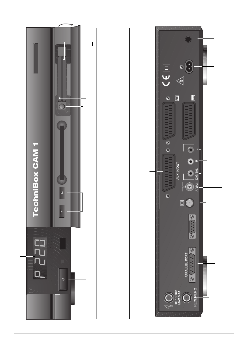
With PCMCIA-interface for two
different independent CA-modules.
For the reception of free-to air and encoded
ASTRA and EUTELSAT DVB-programmes.
Made in Germany
Page 2
2
TechniSat
POWER
ON/OFF
AC 230V
~ 50 Hz
MAX 29 VA
VORSICHT!
ELEKTROSCHOCK-GEFAHR
NICHT ÖFFNEN!
CAUTION!
RISK OF ELECTRIC SHOCK
DO NOT OPEN!
TV
TV
AUDIO OUT
SERIAL PORT
VCR
4-digit LED-display
Scart socket
VCR
Serial port RS-232
Parallel
port
Scart socket TV
Scart socket AUX
Outputs
audio analogue/digital
HF output
Channel
up/down
Reject of
CA-module
Slot A (top)
Slot B (bottom)
Power
Input terrestrial antenna
Mains
socket
Mains switch
(POWER ON/OFF)
LNB output
LNB input
Inserting a CA module:
> Carefully follow the instructions from the manufacturers of card and module.
> Insert the smart card into the corresponding CA module.
> Insert the module in the direction of the arrow (arrow upside) as far as it will go into slot A or B.
> To remove the module, please press the reject button.
Page 3
3
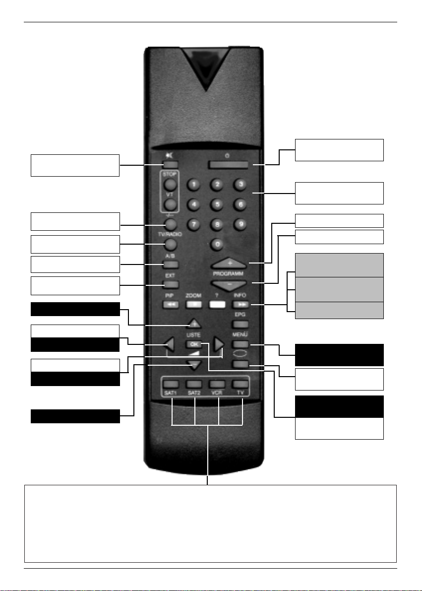
Power
Number keys
Channel list
Back
Menu
Mute
EXTERN
Language A/B
Channel -
Information (blue)
Programme
information (yellow)
Transponder
information (green)
Volume +
Channel +
TV/Radio
MONO1/MONO2
OK
Volume -
Cursor right
Cursor left
Cursor up
Cursor down
Remote control option:
For the operation of 2 TechniSat receivers, 1 TechniSat TV set
and a further future option (e.g. VCR).
Use these buttons to adjust the remote control to SAT 1 to operate your
TechniBox CAM 1, if you did not change them like described under 5.2.2.
> Press the buttons SAT1 and OK at the same time!!!
Remote Control
Page 4

4
Contents
1 Illustrations . . . . . . . . . . . . . . . . . . . . . . . . . . . . . . . . . .2
2 Contents . . . . . . . . . . . . . . . . . . . . . . . . . . . . . . . . . . . .4
3 Safety precautions Ð Please read first! . . . . . . . . . . . . .6
4 Connection . . . . . . . . . . . . . . . . . . . . . . . . . . . . . . . . . . .7
4.1 Mains connection . . . . . . . . . . . . . . . . . . . . . . . . . . . . . . . . . . . . . . .8
4.2 Outdoor unit . . . . . . . . . . . . . . . . . . . . . . . . . . . . . . . . . . . . . . . . . . .8
4.2.1 Single reception . . . . . . . . . . . . . . . . . . . . . . . . . . . . . . . . . . . . . .8
4.2.2 Operation with an additional receiver . . . . . . . . . . . . . . . . . . . . . .8
4.3 Connection to a TV set . . . . . . . . . . . . . . . . . . . . . . . . . . . . . . . . . . .8
4.4 Adjusting the UHF output channel . . . . . . . . . . . . . . . . . . . . . . . . . . .9
4.5 Video Cassette Recorder (VCR) . . . . . . . . . . . . . . . . . . . . . . . . . . .10
4.5.1 Super VHS VCR . . . . . . . . . . . . . . . . . . . . . . . . . . . . . . . . . . . . .10
4.6 AUX IN/OUT . . . . . . . . . . . . . . . . . . . . . . . . . . . . . . . . . . . . . . . . . .10
4.7 Amplifier . . . . . . . . . . . . . . . . . . . . . . . . . . . . . . . . . . . . . . . . . . . . .10
4.8 Serial/parallel port . . . . . . . . . . . . . . . . . . . . . . . . . . . . . . . . . . . . . .11
5 Settings . . . . . . . . . . . . . . . . . . . . . . . . . . . . . . . . . . . .11
5.1 OSD language . . . . . . . . . . . . . . . . . . . . . . . . . . . . . . . . . . . . . . . .11
5.2 Basic settings . . . . . . . . . . . . . . . . . . . . . . . . . . . . . . . . . . . . . . . . .12
5.3 Installation . . . . . . . . . . . . . . . . . . . . . . . . . . . . . . . . . . . . . . . . . . .14
5.4 Channel search . . . . . . . . . . . . . . . . . . . . . . . . . . . . . . . . . . . . . . . .16
5.5 Common Interface . . . . . . . . . . . . . . . . . . . . . . . . . . . . . . . . . . . . .18
5.6 Reset to factory settings . . . . . . . . . . . . . . . . . . . . . . . . . . . . . . . . .19
5.7 System configuration . . . . . . . . . . . . . . . . . . . . . . . . . . . . . . . . . . . .20
6 Changing the basic setting . . . . . . . . . . . . . . . . . . . . .20
6.1 Adding/Deleting of channels in the user list . . . . . . . . . . . . . . . . . . .20
6.2 Sorting of channels . . . . . . . . . . . . . . . . . . . . . . . . . . . . . . . . . . . .21
6.3 Locking of channels . . . . . . . . . . . . . . . . . . . . . . . . . . . . . . . . . . . .21
6.4 Changing the PIN . . . . . . . . . . . . . . . . . . . . . . . . . . . . . . . . . . . . . .22
6.5 Cancelling the locking of individual channels . . . . . . . . . . . . . . . . . .22
7 Operation . . . . . . . . . . . . . . . . . . . . . . . . . . . . . . . . . . .22
7.1 Switching on/off . . . . . . . . . . . . . . . . . . . . . . . . . . . . . . . . . . . . . . .22
7.2 Channel selection . . . . . . . . . . . . . . . . . . . . . . . . . . . . . . . . . . . . . .22
7.2.5 Information box . . . . . . . . . . . . . . . . . . . . . . . . . . . . . . . . . . . . . .23
7.3 Reception of encoded programmes . . . . . . . . . . . . . . . . . . . . . . . . .23
7.4 Volume control . . . . . . . . . . . . . . . . . . . . . . . . . . . . . . . . . . . . . . . .23
7.5 Language selection . . . . . . . . . . . . . . . . . . . . . . . . . . . . . . . . . . . . .24
7.6 TV/Radio . . . . . . . . . . . . . . . . . . . . . . . . . . . . . . . . . . . . . . . . . . . .24
7.7 Returning to the previous channel . . . . . . . . . . . . . . . . . . . . . . . . . .24
7.8 Display of time and programme information . . . . . . . . . . . . . . . . . . .24
7.9 Additional programme information . . . . . . . . . . . . . . . . . . . . . . . . . .24
7.10 Transponder information . . . . . . . . . . . . . . . . . . . . . . . . . . . . . . .25
7.11Teletext . . . . . . . . . . . . . . . . . . . . . . . . . . . . . . . . . . . . . . . . . . . . . .25
7.12 Timer operation . . . . . . . . . . . . . . . . . . . . . . . . . . . . . . . . . . . . .25
8 Troubleshooting notes . . . . . . . . . . . . . . . . . . . . . . . . .26
9 Technical terms . . . . . . . . . . . . . . . . . . . . . . . . . . . . . .27
10 Technical data . . . . . . . . . . . . . . . . . . . . . . . . . . . . . .29
Page 5
Using the operating instructions
> Before connecting the receiver, please read the safety precautions in chapter 3 first.
> The chapters 4 and 5 describe the initial installation, how to connect and adapt the
receiver to the outdoor unit (antenna, LNB,...), to the TV, VCR, etc.. This set-up is required at initial installation and only needs to be supplemented if the outdoor unit changes
or additional equipment are connected.
> In chapter 6 you will find information about storing new channels and changing the
channel sequence.
> Chapter 7 describes all important functions for every-day use, such as channel selec-
tion or volume control.
> Troubleshooting notes can be found in chapter 8.
> Technical terms used in the operation instructions are explained in chapter 9.
> The technical data can be found in chapter 10.
Important notes on handling the device
The use of a so-called "On-Screen Display" (OSD) simplifies the receiver control and reduces the number of keys on the remote control. All functions are displayed on the TV screen
and can be controlled with a few key strokes.
Related functions are grouped into a "MENU". The active function is marked by a blue "CURSOR" line. In the lower half of the screen a short comment to the marked function is inserted.
Terms used in the OSD menu, remote control keys and switches and sockets are printed
bold in this instruction manual.
For example:
> Call Main Menu with the MENU button.
> Choose the menu line Settings by marking the corresponding line red with the help of
the cursor keys up/down
> Confirm with OK.
Main menu
TV Programs
Radio Programs
Search
Timer
Settings
OSD Language
5
Page 6
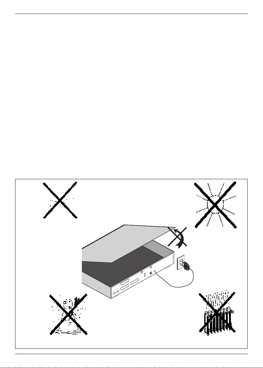
3 Safety precautions
For your own protection, carefully read the safety precautions before starting to use your
new device.
The manufacturer is not liable for damage caused by improper handling or by disregarding
the safety precautions.
> Never place any objects on top of the device. The openings need to be uncovered for
heat to escape from the inside.
> Never open the device! There is danger of an electric shock. Repairs should only be car-
ried out by trained personnel.
> Take care that empty remote control batteries are not put into the household waste but
disposed off properly (return to specialist stores, special waste).
Operational breaks:
During a storm or when operation is interrupted for a long time disconnect the device from
mains.
In the following cases disconnect the device from mains and ask an expert
for help:
> the power supply cord or the connector is damaged
> the device was exposed to humidity or a liquid has flown into the device
> in case of considerable malfunctions
> in case of considerable external damage.
6
>80%
<+15°C
+35°C
230V
~
B
(R
)-A
U
D
IO
-(L
)A
M
A
D
E
IN
G
E
R
M
A
N
Y
I
G
T
E
S
T
V
ID
E
O
A
N
T
T
V
L
N
B
D
C
1
3
/1
8
V
M
A
X
0
,4
A
( )
K
A
N
A
L
2
3
0
-2
4
0
V
5
0
H
z
m
a
x
. 2
4
V
A
V
C
R
/D
E
C
O
D
E
R
T
V
D
E
C
O
D
E
R
Page 7
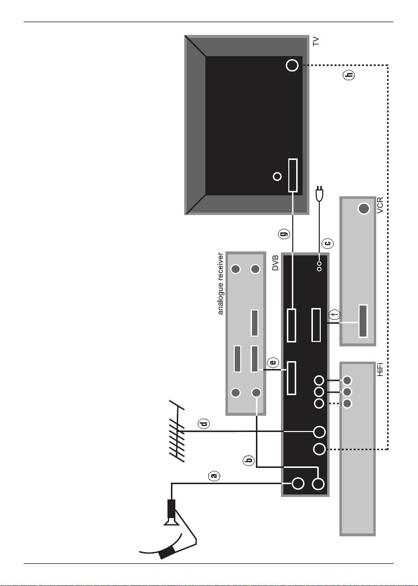
7
Connecting the DVB receiver with
a satellite system
a. Connecting the LNB with the LNB input of the DVB receiver.
b. Connecting the LNB output of the DVB receiver with the LNB input of the ana-
logue receiver
c. Mains connection
d.. Connecting the terrestrial antenna with the antenna input ARIAL of the DVB
receiver
e. Connection of an analogue device with the Scart socket AUX IN/OUT of the
DVB receiver.
f. Connection of a VCR with the VCR Scart socket of the DVB receiver.
g. Connection of the TV set with the TV Scart socket of the DVB receiver.
Optional:
h. Connecting the HF output TV of the DVB receiver with the HF input socket of
your TV set.
Page 8

4 Connection
The letters a b c ... found in the following paragraphs refer to the drawing on page 7.
4.1 Mains connection
The receiver should only be connected to the mains after the cabling with all components is
completed. This eliminates damage to the receiver or other components.
c After completion of all connections use the enclosed power cord to connect the mains
socket of the receiver to the mains power supply 230V/50 Hz.
4.2 Outdoor unit
4.2.1 Single reception
a Connect the LNB input of the receiver with the LNB of the outdoor unit using a suitable
coaxial cable. (See also 5.3 " Installation ".
4.2.2 Use of an additional receiver in a single reception system
b If another unit is to be used in a single reception system (for example an analogue or
ADR receiver) you can connect the LNB input of the additional receiver with the LNB
output of the DVB receiver with a suitable coaxial cable. In order for the additional recei-
ver to also be provided with the satellite signal your DVB receiver must be in the " stand-
by mode ". If the DVB receiver is switched on it takes the LNB signal with priority.
4.3 Connection to a TV set
4.3.1 Via SCART cable:
In order to achieve the best possible picture quality you should connect the receiver and the
TV set with a SCART cable.
Proceed as follows:
g Connect receiver (SCART socket TV) and TV set (SCART socket) with a SCART
cable. If equipped accordingly, your TV set will switch automatically to AV and to satellite
reception when the receiver is turned on.
4.3.2 Via HF cable:
If your TV set is not equipped with a SCART socket the receiver needs to be connected to
the antenna input of the television. With this connection only mono sound will be possible.
For connection proceed as follows:
h Connect the receiverÕs HF output TV with the antenna input of the TV set using a suita-
ble cable. Connect the cable coming from the terrestrial antenna with the terrestrial
antenna input ARIAL of the receiver (d).
Now your TV set needs to be adjusted to the transmitting channel of the receiver. Choose a
free channel position at the TV set and adjust it to channel 38 (see instruction manual of TV).
If no clear picture is received on channel 38 it might already be occupied by a channel received via antenna. You can determine this by removing the antenna cable from the socket
ARIAL (input terrestrial antenna) of the receiver. If you receive a clear picture now, you
should use a different transmitting channel in the range 21 to 61.
8
Page 9
4.4 Adjusting the UHF output channel
Proceed as follows:
> Call Main Menu with the MENU button.
> Choose the menu line Basic Settings by marking the corresponding line red with the
help of the cursor keys up/down.
> Confirm with OK. The sub-menu Settings appears.
> Choose the menu line Basic Settings by marking the corresponding line red with the
help of the cursor keys up/down.
> Confirm with OK. The sub-menu Basic settings appears.
> Choose the menu line UHF Output Channel by marking the corresponding line red
with the help of the cursor keys up/down.
> Set your TV set to a free UHF channel between 21 and 61.
Main Menu>Settings>Basic
Parental Control off
Screen Format (TV) 4:3
Language (audio signal) English
GMT Time Offset (hrs.) +1
Country None
UHF Output Channel 38
SCART Mode RGB
RC Code Sat 1
Main Menu>Settings
Change PIN
Basic Settings
LNB Settings
System Configuration
Common Interface
Factory Settings
Main menu
TV Programs
Radio Programs
Search
Timer
Settings
OSD Language
9
Page 10

> Enter the new output channel number with the number keys of your remote control.
The new UHF channel is now indicated on the receiver display.
If you still do not receive a clear picture, please repeat this procedure until you have
found a suitable channel.
> After you have found an optimal UHF channel make sure you store it on your TV set.
> Now you can make further adjustments in the menu Basic Settings or press the
MENU button to leave it. On leaving the menu these settings are automatically stored.
> If your TV set only is equipped with an automatic station finder set your receiver to any
UHF channel and then start the automatic station search on your TV. Please repeat this
procedure until you have found a suitable channel and store it on the TV set.
> Fine tuning of this channel on your TV set might still be necessary.
4.5 Video Cassette Recorder (VCR)
f Connect the VCR to the SCART socket VCR. In the "play" mode the VCR transmits a
switching signal to the receiver, thus leading the VCR signal to the TV set automatically.
If the VCR does not send a switching signal, you can switch your receiver to the external
input AV1 with the button EXT. Pressing the button once again, the input AV2 is
activated. If the button is pressed a third time, the receiver turns back to normal mode.
4.5.1 Super VHS VCR
If you have a super VHS video recorder you can record in super VHS quality. To do so, please adjust settings like shown in 5.2.1 (Basic settings).
! Warning ! This adjustment affects the SCART sockets for TV and VCR.
4.6 AUX IN/OUT
e Spare socket for connection of an analogue receiver, an additional TV set orVCR (AV2).
4.7 Amplifier
4.7.1 Analogue
In order to reach the best possible sound quality you can connect the receiver to a hi-fiamplifier. Connect the cinch sockets AUDIO OUT R and AUDIO OUT L of the receiver with
the input of your hi-fi amplifier (e.g. CD or AUX; ! Warning ! do not use phono input) with a
suitable cable
4.7.2 Digital
If your amplifier is equipped with an electrical input, connect it with the AUDIO OUT DIGITAL socket.
The following sampling rates are available: 16-, 22.05-, 24-, 32-, 44.1 and 48 kHz.
10
Page 11

4.8 Serial port RS 232
The SERIAL PORT RS 232 is used for updating the operation software and pre-programming via PC.
4.8 Parallel port IEEE 1284
The PARALLEL PORT is used for data exchange via a PC with a special software. Since
there is no application for this at present the existing software does not support this function.
5 Settings
Now, that you have completed the installation of your new receiver and switched it on you
can optimise the receiver to your needs, if necessary.
5.1 OSD language
This menu enables you to adjust the language used in the OSD menus. You can choose between the languages German, English, French, Italian, Turkish, Danish, Norwegian, Swedish,
Finnish, Polish and Spanish.
To change the OSD language proceed as follows:
> Call Main Menu with the MENU button.
> Choose the menu line OSD Language by marking the corresponding line red with the
help of the cursor keys.
> Confirm with OK..
The sub-menu OSD Language appears.
> Mark the desired language with help of the cursor keys. With the buttons cursor
up/down the marker moves a line up or down, the cursor keys left/right turn to the
previous or next page.
> Store adjustment by pressing the button OK.
> Leave the menu by pressing the MENU button.
Main menu
TV Programs
Radio Programs
Search
Timer
Settings
OSD Language
11
Page 12

5.2 Basic settings
In order to be able to optimally use your DVB receiver, you need to adjust it to your individual
needs.
> Call Main Menu with the MENU button.
> Choose the menu line Settings by marking the corresponding line red with the help of
the cursor keys.
> Confirm with OK.
The sub-menu Settings appears.
5.2.2 Further Basic Settings
> Choose the menu line Basic Settings by marking the corresponding line red with the
help of the cursor keys.
> Confirm with OK.
The sub-menu Basic Settings appears.
> With the buttons cursor up/down the marker moves a line up or down within the
menu. Keep an eye on messages that might appear on the screen.
Main Menu>Settings>Basic
Parental Control off
Screen Format (TV) 4:3
Language (audio signal) English
GMT Time Offset (hrs.) +1
Country None
UHF Output Channel 38
SCART Mode RGB
RC Code Sat 1
Main Menu>Settings
Change PIN
Basic Settings
LNB Settings
System Configuration
Factory Settings
12
Page 13

Explanation for the OSD menu:
Main Menu>Settings>Basic
Parental Control:
The receiver is equipped with a child lock. Channels that have been locked according to
6.3 and 6.4 can only be tuned in after a 4-digit PIN has been entered. Here the child lock
function can be switched on or off by pressing the OK button.
Screen Format (TV):
Adjust the picture format to 4:3 or 16:9 according to your TV set by pressing the OK button. This function adjusts the picture format automatically to your TV set.
Language (audio signal)
Select your preferred language with help of the OK button. This function makes sure that
broadcasts will automatically be shown in that language, if available.
GMT Time Offset (hrs.)
Your receiver is equipped with a clock which is synchronised via satellite to the Greenwich
Mean Time. All you need to do is to enter the time difference to your local time with the
OK button. (For Germany enter +1 hour, during summertime +2 hours.) In standby mode
the time will be indicated in the display.
Country
This function changes automatically from winter to summertime. Here, please enter your
country with the help of the OK button.
Since this information is not transmitted by all broadcasters at present, please leave the
setting to None for the moment.
UHF Output Channel
See 4.4 Adjusting the UHF output channel.
SCART Mode
Adjust to CVBS, RGB or S-VHS according to your TV set with the OK button. For standard TV sets, please leave setting to RGB.
IRC Code (Remote control code)
Select one of the remote control options SAT1 or SAT2 you would like to use with the
help of the OK button
Keep in mind, that, if changed, you also need to adjust the remote control.
Leave the menu by pressing MENU.
13
Page 14
14
5.3 Installation
After you have adjusted your receiver to your individual needs you may have to adjust it to
your antenna, if necessary. The receiver was factory pre-programmed to ASTRA and
EUTELSAT with a Universal-LNB (see appendix: Technical terms). These channels will be
received after installation of the receiver without additional adjustments.
If you would like to receive different satellites or use a different LNB you need to adjust your
receiver as follows:
> Call Main Menu with the MENU button.
> Choose the menu line Settings by marking the corresponding line red with the help of
the cursor keys up/down.
> Confirm with OK.
The sub-menu Settings appears.
> Choose the menu line LNB settings by marking the corresponding line red with the
help of the cursor keys up/down.
> Confirm with OK.
The sub-menu LNB appears.
The following adjustments can be made in this sub-menu:
5.3.1 DiSEqC on / off
DiSEqC is used for the control of big antenna systems (see appendix: Technical terms).
> Turn DiSEqC on or off with the OK button.
5.3.2 Adjustments of the switching matrix and LNB settings
The menu lists the four switching criteria of the DiSEqC control. The device is pre-programmed to receive ASTRA in the position A/A and EUTELSAT in position B/A of a multiswitch. If
the switching matrix of your reception unit should have been differently set up or receives different satellites you can adjust the receiver to your individual needs.
> Select the DiSEqC position/option you would like to change (e.g. DiSEqC A/B-no satelli-
te) by marking the line in the satellite column red with the help of the cursor keys +/-
and up/down.
> Confirm with OK.
A selection of different satellites appears.
Main Menu>Settings>LNB
DiSEqC on
DiSEqC Satellite LNB Test
Position/Option
A/A ASTRA 19.. continue
B/A EUTELSAT 13.. continue
A/B no satellite continue
B/B no satellite continue
Page 15

> Select the desired satellite with help of the cursor keys. With the buttons cursor
up/down the marker moves a line up or down, the cursor keys left/right turn to the
previous or next page. If the desired satellite does not appear on the list, please select
one of the spare positions, marked with User 1 to 17 (e.g. User 1).
> Confirm with OK.
The selected line is then inserted into the previously marked line of the menu
Settings>LNB.
Continue adjusting the menu Settings>LNB until it corresponds to your reception unit.
Insert No Satellite for not needed criteria.
5.3.3 More Settings
After the switching matrix of your DVB receiver has been adjusted to your reception system
you need to check the other settings for your reception system and adjust them if necessary.
Proceed as follows:
> Select Proceed in the column Check LNB of the satellite to be tested.
> Confirm with OK
The sub-menu Check appears with the selected DiSEqC settings (e.g. A/B).
Explanation for the OSD menu:
Main Menu> Settings>LNB
LOF low band:
LOF (local oscillator frequency) is the frequency used by the LNB to convert the recei-
ved frequency to a so-called 1st intermediate frequency which then can be fed into the
receiver. Universal LNBs use 2 LOFs to convert the complete frequency range from 10.7
to 11.8 GHz (low band) and 11.7 to 12.75 GHz (high band).Please, enter here the LOF
frequency of the low band of your LNB with the number keys.
LOF high band
Please, enter here the LOF frequency of the high band of your LNB with the number
keys.
Transition LOF low/high
Please, enter here the frequency where the LNB changes from low band to high band
with the number keys.
15
Page 16

16
Transponder test
You only need to enter the following points, if you want to test a satellite signal of a satellite you entered yourself (User 1 to 17).
Transponder frequency
Please, enter the frequency for the transmission of digital broadcasts with the help of the
number keys.
Polarization
Enter the polarisation level (horizontal or vertical) of the desired programme with help of
the OK button.
Symbol rate
The symbol rate indicates the amount of data transmitted per second (e.g. 27,000 symbols
per second). Enter the correct symbol rate with the number keys.
FEC rate
With the FEC the error correction is adjusted according to the desired transponder. Enter
the FEC with help of the number keys (e.g. 1/2, 2/3, 3/4, 5/6, 6/7 or 7/8).
Signal
This line indicates the signal strength after all settings of the transponder have been entered correctly.
Red bar
Bad reception, no digital reception possible.
Yellow bar
good reception
Green bar
very good reception
5.4 Channel search
As already mentioned, your receiver is pre-programmed for the reception of the satellites
ASTRA and EUTELSAT. To receive other channels i.e.. channels of other satellites, you
have several possibilities for a channel search. After the channel search, the screen displays the number of channels your receiver has found. It also displays how many of those
channels are new ones. New channels are marked red in the channel list and can be
added to the user list (see 6 Changing the basic setting). To start the channel search, call
the sub-menu Search:
Page 17

> Call the main menu with the MENU button.
> Now choose the menu line Search by marking it red using the cursor keys up/down.
> Confirm with OK.
The sub-menu Search appears
5.4.1 All
By activating the All function, all adjusted satellites and transponders are being searched
through. New channels are then shown in red in the channel list.
> Choose the menu line All by marking it red with the cursor keys up/down.
> Confirm with OK.
The screen displays: Start search.
> By pressing OK again the channel search is being activated. By pressing BACK or
MENU the function can be stopped. Channel search can take more than 15 minutes.
Please, also observe the OSD.
5.4.2 Satellite
This menu enables a search for one special satellite. All other satellites will be disregarded in
the search.
> Choose menu line Satellite and mark it red using the cursor keys up/down.
> Confirm with OK.
The message Start search appears on the screen.
> You may have to select the satellite to be searched through by pressing OK. A selection
window with the four satellite positions appears.
> Mark the desired satellite by using the cursor keys up/down.
> By pressing OK again the channel search is being activated. By pressing BACK or
MENU the function can be stopped. Channel search can take more than 15 minutes.
Please, also observe the OSD.
Main Menu>Search
All
Satellite
Transponder
Program
Main menu
TV Programs
Radio Programs
Search
Timer
Settings
OSD Language
17
Page 18

5.4.3 Transponder
This menu enables you to start a specific channel search for one transponder (see 9
Technical terms). This, however, requires that the transponder data is entered.
> Choose the menu line Transponder and mark it red by using the cursor keys
up/down.
> Confirm with OK.
The sub-menu Transponder appears.
Explanation for the OSD menu: Main Menu>Search>Transponder
Satellite
Select the satellite carrying the desired transponder.
> Mark the line Satellite by using the cursor keys up/down.
> Confirm with OK.
> Mark the desired satellite by using the cursor keys up/down.
> Confirm with OK.
Transponder frequency
Enter the desired frequency by using the number keys.
Polarization
Enter the polarisation level (horizontal or vertical) on which the desired channel is transmitted with OK.
Symbol rate
The symbol rate indicates the amount of data transmitted per second (e.g. 27,000 symbols
per second). Enter the correct symbol rate with the number keys.
> After you have entered all information, you can start the search by marking the line
Start search and then pressing OK. Please, also observe the OSD.
5.4.4 Channel
If a channel cannot be found with the described procedure (5.4), it may be necessary to
additionally enter a channel-specific service ID number: Call the menu
>Search>Program. The only difference compared to the menu Transponder is the
menu point Service ID.
> Proceed like described under point 5.4.3 Transponder Frequency, just adding the
Service ID number by using the number keys.
5.5 Common Interface
Through this menu point will can enter the subdirectories of the inserted CA modules of slot
A and slot B. To retrieve information about a inserted card, select one slot by marking it red
and confirm with OK. Keep in mind, that CA module and card need to be of the same encoding system.
18
Page 19

5.6 Reset to factory setting
5.6.1 Complete deleting of all channel memories
You can return to the factory LNB setting anytime. You can also delete this completely and
start a new channel search in case the channel list is out-of-date due to broadcaster changes.
Call Main Menu with the MENU button.
> Choose the menu line Settings by marking the corresponding line red with the help of
the cursor keys.
> Confirm with OK.
The sub-menu Settings appears.
> Choose the menu line Factory Settings by marking the corresponding line red with the
help of the cursor keys up/down.
> Confirm wit OK.
The sub-menu Factory setting appears.
Explanation for the OSD menu:
Main Menu>Settings>Factory setting
Restore Factory settings
This function activates the factory setting and deletes individual adjustments.
Delete All Programs
This function deletes all channel memories.
> Select the desired function with help of the cursor keys.
> Confirm with OK.
Keep an eye on appearing messages on the screen.
Main Menu>Settings
Change PIN
Basic Settings
LNB Settings
System Configuration
Factory Settings
Main menu
TV Programs
Radio Programs
Search
Timer
Settings
OSD Language
19
Page 20

5.7 System configuration
In this menu you will find the specific data of the receiver.
> Call Main Menu with the MENU button.
> Choose the menu line Settings by marking the corresponding line red with the help of
the cursor keys.
> Confirm with OK.
The sub-menu Settings appears.
> Choose the menu line System Configuration by marking the corresponding line red with
the help of the cursor keys.
> Confirm with OK.
> Leave the menu by pressing the MENU button.
6 Changing the basic setting
If you do not feel comfortable with the pre-programming of your receiver, you can alter the
programme list to your individual wishes. This function is also needed to sort the channels
after a channel search.
You should consider the following:
This unit has two channel lists: the user defined list and the complete channel list.
The user defined list contains all channels you can recall with the buttons of your remote
control.
The complete channel list contains all channels, those installed at the pre-programming and
those found during the channel search. New channels found during a channel search are
marked red in the list and can be copied into the user defined list.
6.1 Adding / Deleting of channels in the user defined list
To add channels to or delete channels from the user defined list, proceed as follows:
> Call Main Menu with the MENU button.
> Choose the menu line TV Programs to select TV channels or Radio Programs to
select radio channels by marking the corresponding line red with the help of the cursor
keys up/down.
> Confirm with OK.
The sub-menu Programs appears.
> Choose the menu line Select by marking the corresponding line red with the help of the
cursor keys up/down.
> Confirm with OK.
The sub-menu Select appears.
Here you will find a list of the bouquets with their channels. Existing channels are printed
in black and newly found channels are printed in red. Channels listed in the user list are
Main menu >Programs
Select
Sort
Lock
20
Page 21

marked with a red cross. Encoded channels are marked with a key symbol.
> With the help of the cursor keys mark the channel or bouquet you would like to alter.
(-/+ = previous/next page, up/down = line up/down)
The name of a bouquet is marked blue and the channels are marked grey.
> On pressing OK a red cross will be added to this field (entering it to the user defined
list).
If a single channel is added, the picture of that channel is shown in the back ground of
the menu.
On pressing OK again, the red cross will be removed and the selected channel will be
removed from the user defined list. But, it will remain in the complete channel list and
can be added to the user defined list at any time.
If you select a bouquet, the adjustment will be made for the whole bouquet. If you select
a single channel, the adjustment will be made for that channel only.
New channels will be added to the end of the user defined list and can then be sorted to
a different location.
6.2 Sorting of channels
To alter the user defined channel list proceed as follows:
> Call Main Menu with the MENU button.
> Choose the menu line TV Programs to sort TV channels or Radio Programs to
sort radio channels by marking the corresponding line red with the help of the cursor
keys up/down.
> Confirm with OK.
The sub-menu Programs appears.
> Select Sort with help of the cursor keys up/down.
> Confirm with OK
The user defined channel list will appear.
> Select the channel you would like to place at a different location.
> Confirm with OK
> Now you can move the selected channel with help of the cursor keys to the location
in the list you prefer or you can enter the memory position with the number keys of
your remote control. The memory location will be shown in the menu.
> On pressing OK the channel will be placed in the marked position.
> Repeat this procedure until the programmes are in the desired sequence.
> On pressing the MENU button you will leave the menu.
6.3 Locking of channels
You have the possibility to lock channels. If a locked channel is tuned in, you will see a black
screen with the message "Program not available".
A locked channel will be shown on the screen only after you have entered you PIN number.
If you passed by the blockade by entering your PIN the channel will be free to be watched
until the unit has been switched off or into standby mode again.
To lock a channel proceed as follows:
> Call Main Menu with the MENU button.
> Choose the menu line TV Programs to lock TV channels or Radio Programs to
lock radio channels by marking the corresponding line red with the help of the cursor
keys up/down.
> Confirm with OK.
The sub-menu Programs appears.
21
Page 22

> Select the menu line Lock by marking the corresponding line red with the help of the
cursor keys up/down.
> Confirm with OK.
The sub-menu Lock with the user defined channel list appears.
> Now, select the channel you would like to lock with the help of the cursor keys
up/down
> Confirm with OK..
The channel will now be represented with a red cross.
> Repeat this procedure until all desired channels are locked.
To undo locking, press OK. again.
> Leave the menu by pressing the MENU button.
> To activate the child lock you still have to enter you PIN number (see 6.4 Changing
the PIN) and turn the child lock on (see 5.2.2 Further basic settings).
6.4 Changing the PIN
The factory setting of the PIN is 0000. To activate the channel blockade you need to enter
your personal PIN number.
Warning! You must not forget your PIN number. If this occurs anyway, please contact your local dealer!
To change the PIN number, proceed as follows:
> Call Main Menu with the MENU button.
> Choose the menu line Settings by marking the corresponding line red with the help of
the cursor keys up/down.
> Confirm with OK.
The sub-menu Settings appears.
> Select Changing of PIN with the help of the cursor keys up/down.
> Confirm with OK.
> Now enter your new PIN with the help of the number keys.
> Enter it again.
> On pressing OK. you will return to the menu Settings again.
6.5 Cancelling the locking of individual channels
After you have entered your PIN to open the menu proceed like mentioned under 6.3 and
remove the red crosses with the OK button.
This enables you to remove the child lock from individual channels.
7 Operation
7.1 Switching on/off
> Switch your receiver on by pressing POWER at the unit or on your remote control.
> On pressing the POWER button again, the receiver will be turned off.
> Now, the receiver is in standby mode and the time will be indicated in the display of the
receiver.
To completely turn off the receiver press the MAINS SWITCH at the rear of the device.
(Before starting the receiver again, it has to be turned on with the mains switch.)
22
Page 23

7.2 Channel selection
7.2.1 Using the buttons CHANNEL UP/DOWN
> You can change the channel by one up or down on pressing the button CHANNEL
UP/DOWN on the receiver or on the remote control.
7.2.2 Using the number keys
> Enter the channel number with the number keys on your remote control.
For example:
1 for channel 1
1, and then 4 for channel 14
2, and then 3, and then 4 for channel 234
To enter a channel position with more than one digit you have about 3 seconds to enter the
next digit.
If you only want to enter a one-digit or two-digit channel position, you can speed up the process by confirming with the OK button.
7.2.3 Using the channel list
> Press OK
A channel list will appear.
In TV mode only TV channels appear, and in radio mode only radio channels appear.
The current channel is marked blue.
> Now, using the cursor keys you can select a different channel. It will be marked red.
> On pressing OKthe selected channel will be tuned in.
> With the buttons cursor up/down the marker moves a line up or down.
> The cursor keys left/right turn to the previous or next page.
7.2.4 Listing of the locked channels
If you try to tune in to a channel that is locked with Parental control you will see the message
PIN number on the screen.
> Now enter your PIN number with the use of the number keys of your remote control.
The selected channel will now be tuned in.
To make the use more comfortable the PIN number will only be asked for once during one
session. The child lock will only be activated again after the receiver is switched off again.
7.2.5 Information box
After the channel has been changed, an information box will be shown which indicates the
channel name and position. Additional information like TxT for Teletext, 16/9 for broad-
casts in 16/9 format or A/B for different audio channels (e.g. for broadcasts in different languages) will be listed in this information box. In addition, the title of the current broadcast is
displayed, if provided by the broadcaster.
7.3 Reception of encoded broadcasts
This device is equipped with a "Common Interface". This enables you to receive encoded
programmes via so-called CA module. To do so, you need to insert a CA module with a valid
smartcard in one of the provided slots:
> Open the flap on the right side of the unit by pulling it down at the marked spot.
> Insert the CA module into one of the two slots.
23
Page 24

> Insert the smartcard into the card slot of the CA module. Make sure that the golden chip
of the smartcard is on the upper side.
> Now, if an encoded programme is received, the receiver automatically checks both slots
and if it finds the right CA module with an activated and valid smartcard, the programme
will be decoded.
7.4 Volume control
This receiver is equipped with a volume control. This facilitates the handling, because now,
all important functions can be controlled with one remote control.
> Adjust the volume with the buttons VOLUME+ and VOLUME-.
> On pressing the button MUTE the sound will be completely turned off and on pressing it
again turned on.
7.5 Language selection
If a programme is broadcast in several languages you can choose a different language:
> Press the A/B language button.
If the current broadcast is transmitted in different languages you will see a list of the lan-
guages available.
> Mark the desired language with help of the cursor keys up/down.
> Confirm with OK.
Now you will hear the broadcast in the selected language. After a channel change the language will turn back to the pre-selected language (see 5.2.1 Language).
Your can also receive broadcasts in mono. With the switch MONO1/MONO2 you can
switch the sound of a mono broadcast between the sound channel MONO1 and MONO2.
7.6 TV/Radio switch
Besides TV channels, also radio channels are pre-programmed. For radio broadcasts the
picture is turned off and the stationÕs name is shown on the screen.
> Switch the receiver to radio with the TV/RADIO button.
The radio station listened to the last time will be tuned in.
> If the TV/RADIO button is pressed again, the TV station watched the last time will be
tuned in.
7.7 Returning to the previous channel
> The button BACK on your remote control will switch to the station tuned in previously.
> On pressing the button again you will be returned to the station watched/listened to befo-
re.
7.8 Display of time and programme information
This function will display the time and information about the tuned in programme.
> Press INFORMATION to display the information on the screen.
In the lower part of the screen you will now see the current time, the stationÕs name and the
name of the programme with the time of the beginning and end of the broadcast. Provided
that these information are submitted by the broadcaster.
7.9 Additional programme information
> If supplied, you can receive additional information about the programme by pressing the
button PROGRAMME INFORMATION.
> On pressing OK information about the following broadcast will be displayed.
> If PROGRAMME INFORMATION is pressed again, the display will vanish.
24
Page 25

7.10 Transponder information
> On pressing the button TRANSPONDER INFORMATION the data of the transmitting
transponder will be displayed.
> Press this button again to turn the display off.
7.11 Teletext
If supplied, the data of the teletext information can be replayed on the TV.
If there are disturbances like overlapping of teletext and picture, you should switch your
receiver to FBAS mode (see 5.2 Scart mode).
7.12 Timer operation
Your receiver is equipped with a timer function which enables you to record during absence.
Up to 8 events can be pre-programmed:
> Call Main Menu with the MENU button.
> Choose the menu line Timer by marking the corresponding line red with the help of the
cursor keys up/down.
> Confirm with OK..
The sub-menu Timer appears.
The settings for the timer 1-8 are the same:
> Select the field you want to change with the help of the cursor keys -/+ and
up/down.
Explanation for the OSD menu: Main Menu>Timer
Source
Enter TV or Radio with help of the button OK, to record a TV or radio programme.
Program Number/Name
> Press OK.
A channel list will appear. (In TV mode TV channels and in radio mode radio channels.)
> Select a channel by marking it red with the help of the cursor keys up/down.
> On pressing OK the selected channel is chosen.
For channel selection also see 7.2.
Date
Insert the date the programme should be recorded with help of the number keys on your
remote control.
Repetition (Rpt)
With the button OK you can select the repetition of the recording. Possible are: - = timer off,
1x = timer on, D = daily, 1W = weekly, 2W = every second week, 3W = every third week,
4W = every fourth week, 1-5 = every weekday, 6-7 = every weekend.
Time Start/Stop
Enter the time when the recording is to begin and to end with the number keys on your
remote control.
In order for the timer to switch between the recordings, a minimum of 1
minute between the ending time and the beginning time of the next recording is required!
25
Page 26

26
8 Troubleshooting notes
Problem Possible cause What to do
No picture, no sound, No power supply Check main power supply
display is dark
No picture, no sound, Short circuit in LNB cable Turn unit off, remove short circuit,
display is on turn unit on again
Defect or missing cable Check all cable connections
Defect in LNB Replace LNB
Wrong outdoor unit entered Enter correct outdoor unit
(see 5.3)
Outdoor unit not correctly Adjust outdoor unit.
adjusted
On-screen interference. Heavy rain or snow fall Remove snow from outdoor unit
(Rectangular boxes Outdoor unit not correctly Adjust outdoor unit
appear on the screen, adjusted
unit turns to still frame, Dish is too small for your Use a larger dish
no sound. Temporarily location
the screen is black with There might be an obstacle Install dish at an obstacle free the
message "no signal". between dish and satellite location
(e.g. a tree)
Sound ok, no picture A radio channel is tuned in Switch to TV mode
Picture and sound Outdoor unit defect or shifted Check outdoor unit
disturbances in previously Channel is transmitted on a Start channel search
clear channels different transponder
Channel is not transmitted none
any longer
Remote control does Wrong mode Enter mode SAT1 or SAT2
not work
Page 27

9 Technical terms
Antenna cable
Connection between modulator of receiver and antenna input of TV (alternative: if no scart
cable is available).
Outdoor unit
Contains the complete outdoor system, including a parabolic/offset dish and one or several
LNBs for the reception of one or several satellites.
AV (see SCART)
Common Interface (CA)
A common interface standard for decoding modules (also CA module or CAM).
Data compression/MPEG1/MPEG2
The quantity of digital data for the transmission of todayÕs TV standard (625 lines and 50 Hz
picture repetition frequency) amounts to 216 Mbit/sec. The bandwidth needed for this quantity is neither available via terrestrial nor via satellite transmission. Therefore the data quantity
is reduced. In Europe the standard (world wide) for the data compression is MPEG2.
MPEG2 is a extension of MPEG1.
Deemphasis
The adaptation of the audio frequency curve to the transmitting signal is fixed by the transmitting parameters of the satellite.
DiSEqC
Digital Satellite Equipment Control: A digital pilot signal for the control of DiSEqC compatible
components of the outdoor unit via the antenna cable.
DVB
Digital Video Broadcasting: A digital universal transmitting technique for picture, graphic,
sound and text. For any kind of data and in any possible quality.
Frequency
The rate at which a sound wave or radio wave vibrates
The number of vibrations of a sound or radio wave per second. The unit is Hertz (Hz).
Frequency range
a) Satellite e.g. LNB:
11 GHz range from 10.70 GHz to 11.70 GHz
12 GHz range from 11.70 GHz to 12.75 GHz
b) Receiver: intermediate frequency or 1st IF 950 to 2150 MHz
Unit of frequency Name Vibration per second
1Hz 1 Hertz 1
1 kHz 1 Kilohertz 1.000
1 MHz 1 Megahertz 1.000.000
1 GHz 1Gigahertz 1.000.000.000
Coaxial cable
Connecting cable between LNB and satellite receiver for transmission of the received signals
and for the power supply for the LNB.
LNB/LNC (Low Noise Block Converter)
Reception unit in the focal point of the parabolic antenna, converts the satellite frequency
into the intermediate frequency of the receiver.
LOF
Local Oscillator Frequency: measured in MHz or GHz, depending on LNB and received frequency range.
27
Page 28

Reception frequency range of the receive = transmission frequency of the satellite - LOF
Modulation with 22 kHz
Serves as a 14/28 Volts switch and as a switch between 2 LNBs. With universal LNB as
switch for the high range.
Modulator
Installation within the receiver or VCR for connection of a TV via antenna cable.
Mode
Determines whether a programme is received in mono or stereo.
Multyfeed
Outdoor unit, including a parabolic antenna and several LNBs for the reception of different
satellites.
Parabolic antenna
Parabolic moulded antenna made out of metal or coated plastic for bundling of electromagnetic waves sent by the satellite, in its focal point.
Polarisation level
To get the most use of the available frequency range satellites transmit neighbouring channels in different polarisation (horizontal and vertical or clockwise and anticlockwise rotating).
For the reception of both polarisation levels you need two single LNBs or one V/H LNB.
Receiver (see Satellite receiver)
Satellit:
Bezeichnung des Satelliten, meist mit Name und Position auf der Umlaufbahn,
ASTRA . . . . . . . . . . . . . . . . . . . . . . . . . . . . . . . . . . . . . . . . . . . . .19¡ Ost
EUTELSAT . . . . . . . . . . . . . . . . . . . . . . . . . . . . . . . . . . . . . . . . . .13¡ Ost
Satellite
The signals received and converted by the LNB cannot be processed by the TV. The receiver transforms them and sends audio and video signals (AV) to its outputs which can then be
sent to the TV.
SCART
Sockets at TVs, VCRs, satellite receivers and other devices of the home entertainment products for the transfer of audio (sound) and video (picture) signals (AV).
Transponder
Processes one or more channels on a satellite. That is: reception of the data of the ground
station, amplification and transmitting back to earth.
Universal-LNB
A three band LNB for the reception of the frequency ranges FFS (10.70 - 11.70 GHz), BBS
(11.70 - 12.50 GHz) and FFS high band (12.50 - 12.75 GHz).
The whole range is grouped into 2 bands.
Low band: 10.70 - 11.80 GHz; . . . . . . . . . . . . . . . . . . . . . .LOF 9750 MHz
High band 11.70 - 12.75 GHz; . . . . . . . . . . . . . . . . . . . . .LOF 10600 MHz
Supply voltage
The receiver provides the LNB with a voltage of 14 or 18 Volts via the coaxial cable.
Viacces
Digital encoding system.
Intermediate frequency
The frequency range transmitted by the satellite cannot be transferred via a cable and therefore has to be converted into an intermediate frequency range of 950 to 2150 MHz by the
LNB. This makes the transmission to and the processing by the receiver possible.
1st IF = Intermediate frequency
28
Page 29

29
10 Technical data
Front end / channel decoder
Input frequency range 950 .... 2150 MHz
Input frequency level range - 65 dBm ... - 25 dBm
Noise figure 12 dB max.
RF input connector F type, female
Input impedance 75 Ohm
Output for 1st IF (loop-through) 950... .2150 MHz
A receiver connected to the loop-through out
put will still get the LNB signal, even if the
TechniBox CAM 1 is in stand-by mode.
IF output connector F type, female
Output impedance 75 Ohm
IF bandwidth 36 MHz
AFC range ± 3 MHz
Demodulation shaped QPSK
Symbol rate (1) 4... 30 Mbauds, SCPC / MCPC
FEC Coding concatenated Viterbi and Reed Solomon
Viterbi rates 1/2, 2/3, 3/4, 5/6, 7/8, automatic detection,
(K=7)
Roll-off factor 35%
De-multiplexing:
De-multiplexing according to ISO 13818-1
Common Interface: 2 Common Interface slots for CI modules
(underneath the flap)
Power consumption max. 0.3A/5V for each module
Video decoding:
Video compression MPEG2 and MPEG1 compatible
up to MP@ML (main profile @ main level)
Video standard PAL / 25 Hz
Picture-surface 720 pixel x 576 lines
Picture format 4 : 3 / 16 : 9
Conversion 16:9 É 4:3 Automatic adjustment for 16:9 TV sets
(via SCART)
Letterbox filtering for 4:3 TV sets
Audio decoding:
Audio compression MPEG1 & MPEG2 Layer I and II
Audio mode Dual (main/sub), stereo
Sampling frequencies 32 kHz, 44.1 kHz, 48 kHz, and 16 kHz, 22.05
kHz, 24 kHz
Parameter:
Audio output parameter, analogue:
Output levels left/right 0.5 V r.m.s. (nominal)
Output impedance 600 Ohm
THD > 80 dB
Cross talk < - 65 dB
Audio input parameter, analogue:
Input level left/right 0.5 V r.m.s. (nominal)
Input impedance > 40 kOhm
Page 30

Audio output parameter, digital, (SP/DIF):
Output level 0.5 V p-p at 75 Ohm
Sampling frequencies 32 kHz, 44.1 kHz, 48 kHz (Cinch)
Video input parameter:
Video input 1 V p-p + / - 0.3 dB at 75 Ohm
RED input 0.7 V p-p + / - 0.1V p-p at 75 Ohm
GREEN input 0.7 V p-p + / - 0.1Vp-p at 75 Ohm
BLUE input 0.7 V p-p + / - 0.1V p-p at 75 Ohm
Teletext:
De-multiplexing of Teletext according to ETS 300 472
Data insertion in video signal compliant to ITU-R BT.653-2
lines: 6-22 and 320-335
TV-Scart Connector:
Output FBAS with RGB or only FBAS or only S-VHS switchable
VCR-Scart Connector:
Input FBAS with RGB or S-VHS
Output FBAS or S-VHS
AUX-Scart Connector:
Input FBAS and RGB
Output FBAS
Serial interface RS 232:
Type RS 232, bi-directional
Bit rate 115 kbit/s max.
Connector 9 pin D-SUB, female
Function Software and channel lists update
Parallel interface IEEE 1284:
Type IEEE 1284, slave type, bi-directional
Bit rate . . . . . . . . . .< 100 kBytes/s
Connector 25 pin D-SUB, female
Function data transmission between IRD and PC
PLL-Modulator:
Output channel UHF, channel 21 ... 61
Antenna input 47 .... 862 MHz
Input impedance 75 Ohms
Output level 70 dBµV ± 3 dB
Output impedance 75 Ohm
LNB power supply:
LNB current 400 mA max.; short circuit protected
LNB voltage vertical < 14.0 V without load, > 11.5 V at 400 mA
load
LNB voltage horizontal < 20 V without load, > 17.5 V at 400 mA load
LNB disconnection in stand-by mode
22 kHz Modulation Amplitude 0.6 V ± 0.2 V
Software features:
TV 999 TV channels in USER LIST (F 1 Ð F 999)
Radio 999 radio channels in USER LIST (R 1 Ð R
999)
30
Page 31

Channels total approx. 4000 channels in bouquet list
(TV/radio)
Active satellite positions max. 4
(DiSEqC 1.1, SAT POSITION/SAT OPTION)
Satellite positions total 32 (For each of the 32 satellite positions one
carrier is stored to enable the automatic search for this position.)
Remote control system: RC-5
Subsystem address 8 (SAT 1), changeable to 10 (SAT 2)
Modulation frequency 36 kHz
Infra-red wave length 950 nm
Power supply Switch mode power supply
Power consumption < 30 W (operation mode, with LNB 0.4 A)
< 21 W (operation mode, without LNB load)
< 3 W (stand-by mode)
Input voltage range AC 180 V.... 250 V / 47 ... 63 Hz
General conditions
Operating temperature +15¡C ...+35¡C
Humidity < 80%
Dimensions (WxDxH) 370 mm x 270 mm x 65 mm
Weight 2.25 kg
31
Your DVB receiver is licensed and fulfills all necessary EU requirements!
Changes and printing errors excepted. Issue 06/99
TechniSat is a registered trademark of TechniSat GmbH
www.technisat.de
Page 32

The daily application
Switching on/off
> Turn the receiver on by pressing the button POWER at the device or on your remote con-
trol.
> On pressing the POWER button again, the receiver will be turned off.
> Now, the receiver is in standby mode and the time will be indicated in the display of the
receiver.
To completely turn off the receiver from mains use the MAINS SWITCH at the rear of the
device. (Before starting the receiver again, it has to be turned on with the MAINS SWITCH.)
Channel selection
Using the buttons CHANNEL UP/DOWN
> You can change the channel by one up or down on pressing the button CHANNEL
UP/DOWN on the receiver or on the remote control.
Using the number buttons
> Enter the channel number with the number buttons on your remote control.
For example:
1 for channel 1
1, and then 4 . . . . . . . . . . . . . . . . . . . . . . . . . . . . . . . . . . .for channel 14
2, and then 3, and then 4 . . . . . . . . . . . . . . . . . . . . . . . . .for channel 234
To enter a channel position with more than one digit you have about 3 seconds to enter the
next digit.
If you only want to enter a one-digit or two-digit channel position, you can speed up the process by confirming with the OK button.
Using the channel list
> Press OK.
A channel list will appear.
In TV mode only TV channels appear, and in radio mode only radio channels appear.
> The current channel is marked blue. Now, using the cursor keys you can select a different
channel. It will be marked red.
> On pressing OK the selected channel will be tuned in.
> With the buttons cursor up/down the marker moves a line up or down.
> The cursor keys left/right turn to the previous or next page.
Volume control
This receiver is equipped with a volume control. This facilitates the handling, because now, all
important functions can be controlled from one remote control.
> Adjust the volume with the buttons VOLUME+ and VOLUME-.
> On pressing the button MUTE the sound will be turned completely off e.g. on pressing it
again turned on.
914/99
 Loading...