

Page 1
TECAN
Instructions For Use for
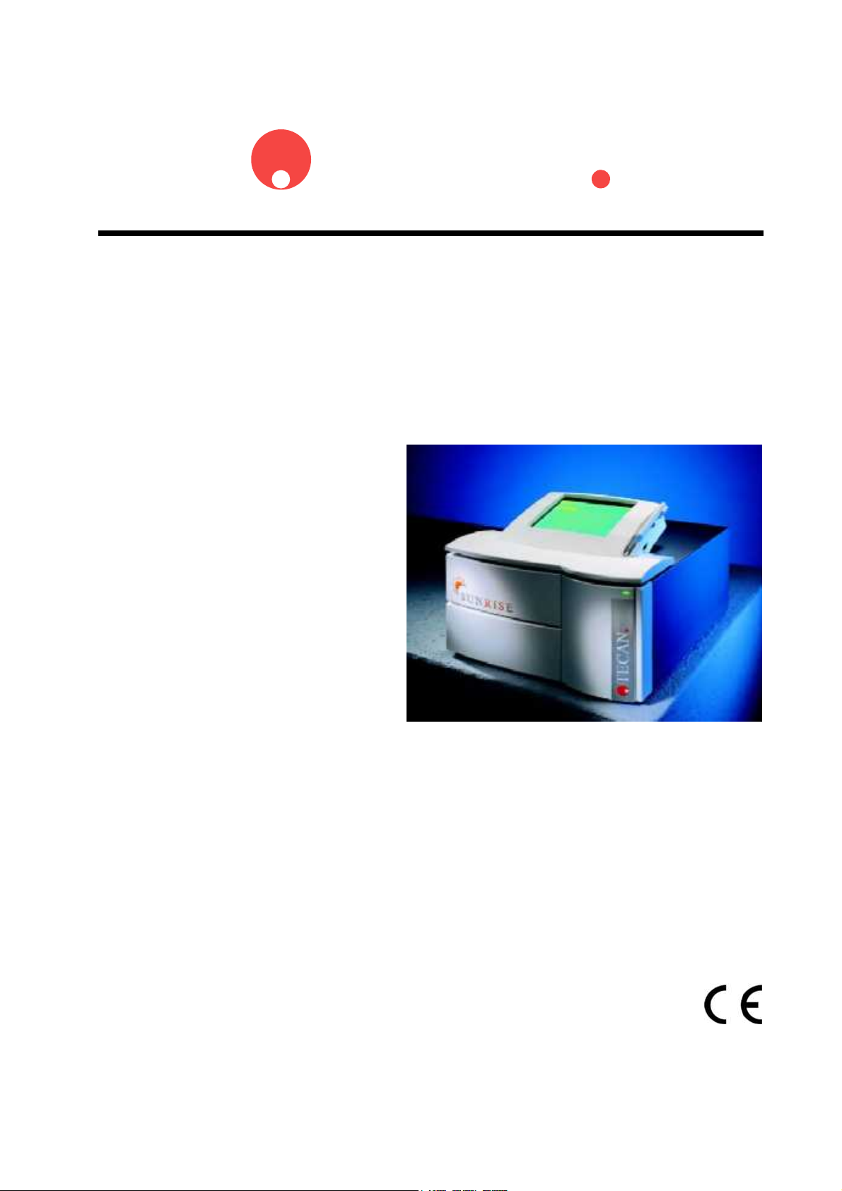
SUNRISE Absorbance
Reader
Document Part No. I 137 311
2003-12
Document Revision No. 1.0
Page 2

Tecan Affiliates and Service Centers
Austria
Tecan Austria GmbH
Untersbergstrasse 1a
A-5082 Grödig / Salzburg
Austria
Tel.: +43 62 46 89 33
Fax: +43 62 46 72 770
Belgium
Tecan Benelux B.V.B.A.
Vaartdijk 55
B-2800 Mechelen
Belgium
Tel.: +32 15 42 13 19
Fax. +32 15 42 16 12
Italy
Tecan Italia S.r.l.
Via F.lli Cervi
Palazzo Bernini
Centro Direzionale Milano2
20090 Segrate (Mi)
Italy
Tel.: +39 02 215 21 28
Fax: +39 02 215 97 441
Spain
Tecan Spain
Sabino de Arana, 32
E-08028 Barcelona
Spain
Tel.: +34 93 490 01 74
Fax: +34 94 411 24 07
United Kingdom
Tecan UK
Theale Court
11-13 High Street
Theale
UK-Reading RG7 5AH
United Kingdom
Tel.: +44 11 89 300 300
Fax: +44 11 89 305 671
Austria
Tecan Sales International GmbH
Untersbergstrasse 1a
A-5082 Grödig / Salzburg
Austria
Tel.: +43 62 46 89 33
Fax: +43 62 46 72 770
France
Tecan France S.A.
Parc d'Activités de Pissaloup
Batiment Hermes II
Rue Edouard Branly
F-78190 Trappes
France
Tel.: +33 1 30 68 81 50
Fax: +33 1 30 68 98 13
Japan
Tecan Japan Co. Ltd
Meiji Seimei Fuchu Building 10F
1-40 Miyamachi
Fuchu City, Tokyo
Japan
Tel.: +81 42 334 88 55
Fax: +81 42 334 04 01
Sweden
Tecan Nordic AB
Box 208, SE-431 23
Mölndal
Sweden
Tel: +46 31 75 44 000
Fax: +46 31 75 44 010
USA
Tecan US
P.O. Box 13953
Research Triangle Park,
NC 27709
USA
Tel.: +1 919 361 5200
Fax: +1 919 361 5201
Asia
Tecan Asia (Pte) Ltd.
80, Marine Parade #13-04
Singapore 449269
Singapore
Tel.: +65 44 41 886
Fax: +65 44 41 836
Germany
Tecan Deutschland GmbH
Theodor-Strom-Straße 17
D-74564 Crailsheim
Germany
Tel.: +49 79 51 94 170
Fax: +49 79 51 50 38
Netherlands
Tecan Benelux B.V.B.A.
Industrieweg 30,
NL-4283 Giessen,
Netherlands
Tel.: +31 018 34 48 17 4
Fax: +31 018 34 48 06 7
Switzerland
Tecan Sales Switzerland AG
Seestrasse 103
CH-8708 Männedorf
Switzerland
Tel: +41 922 8 922
Fax: +41 922 8 923
2 Instructions For Use for SUNRISE Absorbance Reader No. I 137 311 Rev No. 1.0 2003-12
Page 3
WARNING
CAREFULLY READ AND FOLLOW THE INSTRUCTIONS PROVIDED IN
Notice
Every effort has been made to avoid errors in text and diagrams; however, Tecan
Austria GmbH assumes no responsibility for any errors, which may appear in this
publication.
It is the policy of Tecan Austria GmbH to improve products as new techniques
and components become available. Tecan Austria GmbH therefore reserves the
right to change specifications at any time.
We would appreciate any comments on this publication.
Manufacturer
Tecan Austria GmbH
Untersbergstraße 1A
A-5082 Grödig/Salzburg
AUSTRIA / EUROPE
Telephone: 0043 (0)6246/8933
FAX: 0043 (0) 6246/72770
E-mail: office.austria@tecan.com
THIS PUBLICATION BEFORE OPERATING THE INSTRUMENT.
Copyright Information
The contents of this publication are the property of Tecan Austria GmbH and are
not to be copied, reproduced or transferred to another person or persons without
prior written permission.
Copyright Tecan Austria GmbH
All rights reserved.
Printed in Austria.
Declaration for EU Certificate
See the back of this publication.
SUNRISE Absorbance Reader Intended Use
See chapter 2.2.1 Sunrise Intended Use.
About the Instructions For Use
This publication is intended as Instructions For Use for the SUNRISE
Absorbance Reader, which is designed to measure the light absorbance (optical
density) of samples in 96 well microplates. It is intended as reference and
instruction for the user.
This document instructs how to:
• Install the instrument
• Clean and maintain the instrument
Warranty
3 Year Warranty
As an expert for microplate instrumentation Tecan proves its commitment to
quality and offers a unique 3 year warranty for your SUNRISE Absorbance
Reader as a standard. Warranty invalid if instrument is opened or modified.
2003-12 Instructions For Use for SUNRISE Absorbance Reader No. I 137 311 Rev No. 1.0 3
Page 4
Warnings, Cautions and Notes
There are various types of notices used in this publication. These notices
highlight important information or warn the user of a potentially dangerous
situation. The notices used in this publication appear below:
Note:
Gives helpful information.
Caution
Indicates a possibility of instrument damage or data loss if instructions
are not followed.
WARNING
INDICATES THE POSSIBILITY OF SEVERE PERSONAL INJURY, LOSS
OF LIFE OR EQUIPMENT DAMAGE IF THE INSTRUCTIONS ARE NOT
FOLLOWED.
WARNING
INDICATES THE POSSIBLE PRESENCE OF BIOLOGICALLY
HAZARDOUS MATERIAL. PROPER LABORATORY SAFETY
PRECAUTIONS MUST BE OBSERVED.
WARNING
INDICATES LASER. DO NOT STARE INTO THE BEAM!
4 Instructions For Use for SUNRISE Absorbance Reader No. I 137 311 Rev No. 1.0 2003-12
Page 5
Symbols
Manufactured by
Date of manufacture
Communauté Européenne
IVD
In vitro diagnostic medical device
Laser
Biohazardous
2003-12 Instructions For Use for SUNRISE Absorbance Reader No. I 137 311 Rev No. 1.0 5
Page 6

Abbreviations
Abbreviation
A Ampere
Abs Absorbance
C Celsius
CE Communauté Européenne
cm Centimeter
F Fahrenheit
Hz Hertz
IVD In vitro diagnostics
IVD-D In vitro diagnostics Directive
kg Kilogram
l; L Liter
MB Megabyte
µL Microliter
mL Milliliter
nm Nanometer
REF Reference Number/ Order Number
SN Serial Number
TYPE Name and type of instrument
V Volts
VA Volt ampere
VOLTAGE Voltage
6 Instructions For Use for SUNRISE Absorbance Reader No. I 137 311 Rev No. 1.0 2003-12
Page 7

Table of Contents
1. Safety
1.1 Instrument Safety .................................................................1-1
2. General
2.1 Introduction...........................................................................2-1
2.2 Area of Application...............................................................2-3
2.2.1 Sunrise Intended Use .............................................................2-3
2.2.2 Sunrise Variations ..................................................................2-4
2.2.3 Available Options for SUNRISE..............................................2-5
2.3 Specifications .......................................................................2-6
2.3.1 General...................................................................................2-6
2.3.2 SUNRISE Standard Instrument (Standard Filter) ...................2-7
2.3.3 SUNRISE Touchscreen Instrument ........................................2-8
2.3.4 SUNRISE Tuneable Wavelength (Gradient Filter)..................2-9
2.3.5 SUNRISE 6 Filter..................................................................2-10
2.3.6 Temperature Control ............................................................2-10
2.3.7 Barcode Laser Scanner........................................................2-10
2.3.8 Microplates ...........................................................................2-11
2.4 Instrument Description ......................................................2-12
2.4.1 Back Panel Connections.......................................................2-13
2.4.2 Handling the Microplate........................................................2-14
2.5 Filter Carriage Description.................................................2-15
2.5.1 SUNRISE Standard Filter Carriage ......................................2-15
2.5.2 SUNRISE Gradient Filter Carriage .......................................2-15
2.5.3 SUNRISE 6 Filter Carriage ...................................................2-16
2.6 Instrument Features ...........................................................2-16
2.6.1 Measurement Modes............................................................2-16
2.6.2 Microplate Shaking ...............................................................2-17
2.7 Instrument Accessories .....................................................2-18
2.8 Software for the SUNRISE Absorbance Reader...............2-18
3. Installation Procedure
3.1 Introduction...........................................................................3-1
3.2 Unpacking and Inspection ...................................................3-1
3.3 Unpacking Procedure...........................................................3-2
3.4 Power Requirements............................................................3-2
3.5 Environmental Requirements..............................................3-3
3.6 Instrument Installation Procedure ......................................3-3
3.7 Installation of Instrument Control Software.......................3-3
3.8 Defining the SUNRISE Instrument Settings .......................3-4
3.8.1 Installation of SUNRISE Instrument Settings Software...........3-4
2003-12 Instructions For Use for SUNRISE Absorbance Reader No. I 137 311 Rev No. 1.0 7
Page 8

3.8.2 Starting the SUNRISE Instrument Settings.............................3-4
3.8.3 Define Instrument Mode .........................................................3-5
3.8.4 Define Filter ............................................................................3-5
3.8.5 Define Measurement Mode ....................................................3-6
4. SUNRISE Touchscreen
4.1 Introduction...........................................................................4-1
4.2 Area of Application for the Touchscreen Option...............4-2
4.3 Specifications .......................................................................4-2
4.4 Instrument Description ........................................................4-2
4.4.1 Data Handling.........................................................................4-3
4.4.2 Printer Compatibility ...............................................................4-4
4.5 Operating the Touchscreen .................................................4-5
4.5.1 Introduction.............................................................................4-5
4.5.2 Starting the Software ..............................................................4-5
4.5.3 Special Features of MagellanCE ............................................4-6
5. Error Messages and Trouble Shooting
5.1 Introduction...........................................................................5-1
5.1.1 Table of Error Messages and Trouble Shooting for SUNRISE
Mode ...................................................................................................5-1
5.1.2 Table of Error Messages and Trouble Shooting for SPECTRA
Mode ...................................................................................................5-4
6. Maintenance & Cleaning
6.1 Introduction...........................................................................6-1
6.2 Lamp Replacement...............................................................6-1
6.3 Filter Replacement ...............................................................6-3
6.3.1 Standard Filter Carriages........................................................6-3
6.3.2 Gradient Filter Carriages ........................................................6-4
6.3.3 6 Filter Carriages ....................................................................6-4
6.4 Fuse Replacement................................................................6-5
6.5 Cleaning the Instrument.......................................................6-6
6.6 Preventive Maintenance Plan for SUNRISE........................6-6
6.6.1 Daily .......................................................................................6-6
6.6.2 Weekly....................................................................................6-6
6.6.3 Every Six Months....................................................................6-6
6.6.4 Yearly (Service Engineer Required) .......................................6-6
6.6.5 Every Four Years....................................................................6-6
6.7 Instrument Disinfection........................................................6-7
6.7.1 Disinfection Procedure ...........................................................6-7
6.8 Disinfection Declaration.......................................................6-8
6.9 Disposal of Instrument.........................................................6-9
6.9.1 Introduction.............................................................................6-9
8 Instructions For Use for SUNRISE Absorbance Reader No. I 137 311 Rev No. 1.0 2003-12
Page 9

6.9.2 Disposal of Packing Material ..................................................6-9
6.9.3 Disposal of Operating Material ...............................................6-9
6.9.4 Disposal of the Sunrise Instrument.......................................6-10
7. Performance Testing / Quality Control
7.1 Introduction...........................................................................7-1
7.2 Optimizing for Maximum Performance...............................7-1
7.2.1 Instrument Location ................................................................7-1
7.2.2 Operating Procedure ..............................................................7-2
7.2.3 Self Check Procedure.............................................................7-2
7.3 Performance Tests ...............................................................7-3
7.3.1 QC PAC 2...............................................................................7-3
7.3.2 Microplate Test .......................................................................7-3
7.3.3 High Meniscus Liquids............................................................7-5
7.4 Quality Control Testing........................................................7-8
7.4.1 Precision Testing ....................................................................7-8
7.4.2 Instrument Accuracy...............................................................7-9
7.4.3 Instrument Linearity ..............................................................7-10
Index
2003-12 Instructions For Use for SUNRISE Absorbance Reader No. I 137 311 Rev No. 1.0 9
Page 10

Page 11
1. Safety
1. Safety
1.1 Instrument Safety
1. Always follow basic safety precautions when using this product to reduce
the risk of injury, fire or electrical shock.
2. Read and understand all information in this document. Failure to read,
understand and follow the instructions in this publication may result in
damage to the product, injury to operating personnel or poor instrument
performance.
3. Observe all WARNINGS and CAUTION statements in this publication.
4. Never open SUNRISE while the instrument is plugged into a power source.
5. Observe proper laboratory safety precautions, such as wearing protective
clothing and using approved laboratory safety procedures.
WARNING
IF THE SUNRISE ABSORBANCE READER OR THE MAGELLAN
SOFTWARE ARE MODIFIED IN ANY WAY, THE PERFORMANCE OF THE
THE WARRANTY WILL NO LONGER BE VALID AND THE INSTRUMENT
READER MAY BE NEGATIVELY AFFECTED,
WILL NOT BE CE CONFORM.
2003-12 Instructions For Use for SUNRISE Absorbance Reader No. I 137 311 Rev No. 1.0 1-1
Page 12

Page 13
2. General
2. General
2.1 Introduction
Before starting measurements, make sure that the microplate
The SUNRISE instruments are fully automatic, microprocessor controlled readers
designed for professional use, enabling the user to measure the light absorbance
(optical density) of samples in 96 well microplates according to the specifications
described in this publication for in vitro diagnostics.
Note:
SUNRISE Absorbance Reader is intended for use
with only external software.
Caution
position A1 is inserted correctly.
Note:
Results obtained using the SUNRISE are influenced by the proper use of the
instrument and microplates, according to the instructions given in this
document, as well as the liquid compounds used (reagents, chemistry). The
instructions for use, storage and other manipulations in connection with
samples or reagents must be strictly followed. Taking this fact into
consideration, results must be interpreted carefully.
By reading twelve wells simultaneously, the instrument is able to measure a
microplate in approximately six seconds.
The obtained transmission values are converted into OD values according to the
following formula:
I
T onTransmissi
=
I
o
1
Log OD
=
T
=
o
=
With an innovative range of options, this versatile microplate reader gives
diagnostic and research laboratories all the features for numerous purposes.
Based on a new design concept EPAC, the excellent optical performance and
high quality of the SUNRISE will guarantee fast, reproducible and accurate
measurements.
The SUNRISE is designed to be fitted into Tecan robotic systems.
The SUNRISE Absorbance Reader is an optical 96-well microplate reader for the
measurement of absorbance and turbidimetry of samples from the biological or
non-biological origin according to the specifications described in this document,
intended for professional use only.
light emitted I
light detected I
2003-12 Instructions For Use for SUNRISE Absorbance Reader No. I 137 311 Rev No. 1.0 2-1
Page 14
2. General
The SUNRISE Absorbance Reader is available with options Touchscreen,
tuneable wavelength, temperature control and barcode scanner.
The Tecan Sunrise Absorbance Reader when used with the appropriate Magellan
software is declared suitable for in-vitro diagnosis (IVD) purposes (Directive
98/79/EC of the European Community).
Magellan is a reader control and data reduction software package, also used for
concentration and titer determination.
Note:
It is important to note that the proper installation of the instrument and
Magellan software alone will not ensure compliance with the IVD Directive. A
range of policies and standard operating procedures according to local
regulations must also be established.
Make sure that the instrument and the software are suitable for use with the
reagents, chemicals and microplates used (see 7.2 Optimizing for Maximum
Performance and 7.3 Performance Tests).
Caution
If the instructions given in this publication are not correctly followed,
the instrument may become damaged or procedures may not be correctly
performed and the safety of the instrument cannot be guaranteed.
Note:
For more information about the operating instructions,
see Magellan or XFluor4 Instructions for Use.
WARNING
CAREFULLY READ AND UNDERSTAND ALL INFORMATION IN THIS DOCUMENT.
FAILURE TO READ, UNDERSTAND AND FOLLOW THE INSTRUCTIONS IN THIS
PUBLICATION MAY RESULT IN DAMAGE TO THE PRODUCT, INJURY TO OPERATING
PERSONNEL OR POOR INSTRUMENT PERFORMANCE.
2-2 Instructions For Use for SUNRISE Absorbance Reader No. I 137 311 Rev No. 1.0 2003-12
Page 15
2. General
2.2 Area of Application
2.2.1 Sunrise Intended Use
The Sunrise Absorbance Reader is an optical 96-well microplate reader for the
measurement of absorbance including turbidimetry (optical density) of samples
from biological or non-biological origin according to the specifications described in
this manual intended for professional use in:
in-vitro diagnostic environments with tests like:
• Enzyme Immuno Assays (EIA), e.g. for diagnostic of infectious
diseases, autoimmune diagnostic, allergy screening,
• Agglutination Assays, e.g. for blood typing assays,
• Enzyme Assays, e.g. haemostaseology assays and
• Enzyme Linked Probe Hybridization Assays (ELPHA), e.g. HLA-
typing assays,
which have been validated according to the IVD directive or other
relevant regulations or
pharmaceutical, biotechnological and life science industry, for research
use, for food analysis and veterinary applications.
The Sunrise Absorbance Reader has been validated for use with representative
applications from the above list. The validation shows the general ability of the
Sunrise Absorbance Reader to use the above mentioned methods.
Note
If the Sunrise Absorbance Reader or Magellan software
are modified in any way the instrument loses its guarantee
The operating authority must use only CE-labeled test kits for clinical
diagnostic applications. The operating authority must assure that the
combination of a particular CE-labeled test kit used with the CE-labeled
Sunrise Absorbance Reader as been validated according to the IVD
directive or to other relevant national or local regulations.
If the Sunrise Absorbance Reader is used with any other software other than
Magellan, additional validation must be carried out by the operating authority to
ensure the safety of the results. The operating authority is fully responsible for
any results obtained using software other than Magellan with the Sunrise
Absorbance Reader.
and will no longer be IVD compliant.
Note:
2003-12 Instructions For Use for SUNRISE Absorbance Reader No. I 137 311 Rev No. 1.0 2-3
Page 16
2. General
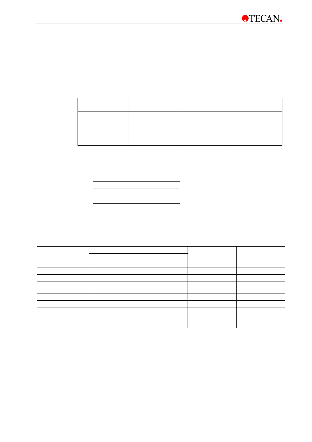
2.2.2 Sunrise Variations
All variations of the Sunrise Absorbance Reader and its Options are compliant
with the IVD directive and part of the CE declaration of conformity.
Sunrise Hardware Variations
The following table shows the compatibility of the filter slides with each
Sunrise hardware variation:
Sunrise
Variations
Standard
6 Filter
Tuneable
Wavelength
Sunrise Options
The Sunrise options work with all hardware variations and accessories and can
be used in any combination:
Sunrise Options
Temperature Control
Touch screen
Barcode
Sunrise Accessories
The Sunrise accessories work with all hardware variations and options and can
be used in any combination:
Sunrise
Accessories
4 Filter Slide
6 Filter Slide
Gradient Filter
Sunrise Instrument
Settings
XFluor 4
Magellan
Magellan TS
QC Pac 1
QC Pac 2
Included in CE1 Separate CE2
4 Filter Slide 6 Filter Slide
X
X X
X X
IVD Compliant
X
X
X
X
X
X
X
X
X
Research Use
Only
Gradient Filter
Slide
None/ Unrelated3
1
IVD compliant. Included in the CE declaration for the instrument.
2
IVD compliant. CE declaration is separate from that of the instrument.
3
Can be used in an IVD environment. CE declaration does not exist or it is unrelated to IVD compliance.
2-4 Instructions For Use for SUNRISE Absorbance Reader No. I 137 311 Rev No. 1.0 2003-12
Page 17
2. General
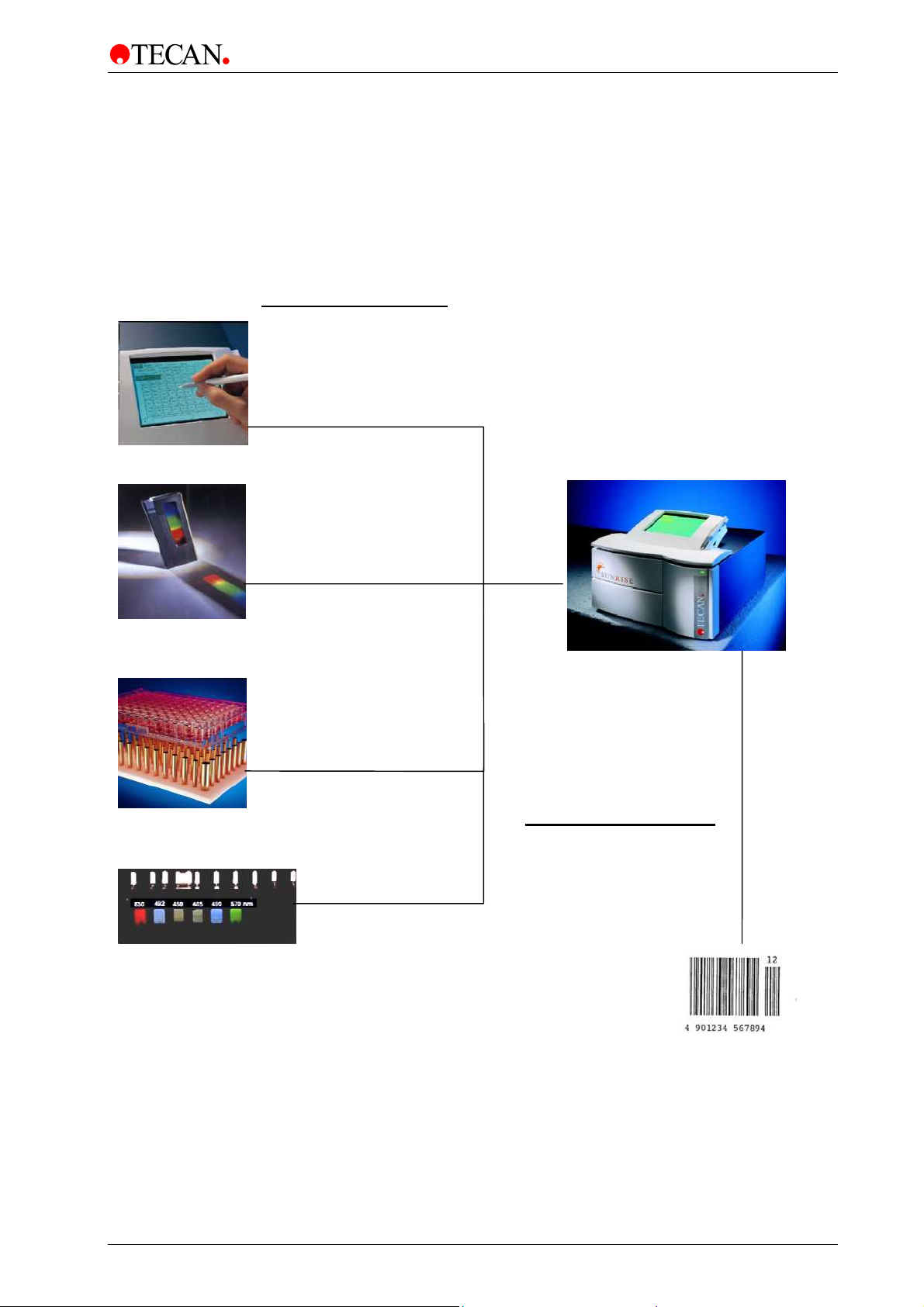
2.2.3 Available Options for SUNRISE
The SUNRISE is a modular system, so you can create your own tailor-made
instrument that meets exactly your needs. Options such as a Touchscreen
combined with a WindowsCE based on-board software, free wavelength
selection, temperature control and a bar code scanner can be added onto the
basic system which is dedicated to remote controlled computer operation.
Factory Installed Options
Touchscreen
B037302
Tuneable wavelength
from 400 – 700 nm
B037306
Temperature Control
SUNRISE Absorbance Reader
B037303
Upgrade in Field Possible
Barcode scanner
B037304
Barcode Upgrade Kit
6 Filter
B03641002
S 039 386
2003-12 Instructions For Use for SUNRISE Absorbance Reader No. I 137 311 Rev No. 1.0 2-5
Page 18

2. General
2.3 Specifications
The tables below lists the specifications for the instruments.
2.3.1 General
For all instrument options:
PARAMETERS CHARACTERISTICS
Mains Power Input
Consumption
Fuse Rating
Outside Dimensions
Weight
Ambient Temperature:
Operation 15°C to 35°C (59°F to 95°F)
Storage -40°C to 60°C (-40°F to 140°F)
Relative Humidity:
Operation 20 % to 90 %
Storage 5 % to 95 %
Overvoltage Category
100 - 120 & 220 - 240 V ± 10% 50/60 Hz
(Auto sensing)
Stand by mode: approx. 50 VA
Operational mode: max. 110 VA
2 x F 2.0 A / 250 V (Fast Blow)
Width: 33,5 cm
Depth: 32,0 cm
Height: 17,0 cm
6 kg
II
Pollution Degree
Method of disposal
Environment
Stability:
Normal measurements
2
Contaminated waste
See 3.5 Environmental Requirements for
more information.
After 15 minutes warm up time
max. +/- 0.001 Abs
2-6 Instructions For Use for SUNRISE Absorbance Reader No. I 137 311 Rev No. 1.0 2003-12
Page 19

2. General
2.3.2 SUNRISE Standard Instrument (Standard Filter)
PARAMETERS CHARACTERISTICS
Measurement time:
dual wavelength
single wavelength
Wavelength Range
Standard
Filter Wavelength Accuracy
Filter Bandwidth
At 50% transmission:
Measurement Range:
340 – 399 nm
400 – 750 nm
Resolution: 0.001 Abs.
Accuracy:
(492 nm) 0.000 - 2.000 Abs
(492 nm) 2.000 - 3.000 Abs
Precision:
(492 nm) 0.000 - 2.000 Abs.
(492 nm) 2.000 - 3.000 Abs.
8 seconds
6 seconds
340 - 750 nm
Central wavelength +/- 2 nm
10 +/- 2nm
0 - 3.000 Abs
0 - 4.000 Abs
Better than +/- 1.0 % +/- 0.010 Abs.
Better than +/- 1.5 % +/- 0.010 Abs.
Better than +/- 0.5 % +/- 0.005 Abs
Better than +/- 1.0 % +/- 0.005 Abs
Linearity:
(340 - 399 nm) 0.000 - 2.000 Abs.
(400 - 750 nm) 0.000 - 2.000 Abs.
2.000 - 3.000 Abs.
Wavelength selection:
Standard filter
Light source:
All connected devices must
be approved and listed as per
EN 60950, UL 1950 or
CSA C22.2 No. 950 for Data
Processing Devices.
Computer interface:
Serial RS 232 C
Printer
Better than +/- 2 %
Better than +/- 1 %
Better than +/- 1.5 %
Narrow band interference filters. Up to four
filters can be mounted in a filter carriage.
The instrument can use up to eight different
filter carriages.
Halogen lamp 20 W
300 - 38,400 baud
Only functions with the Touchscreen
option.
2003-12 Instructions For Use for SUNRISE Absorbance Reader No. I 137 311 Rev No. 1.0 2-7
Page 20

2. General
2.3.3 SUNRISE Touchscreen Instrument
PARAMETERS CHARACTERISTICS
Screen Size
Operating System
Operating Software: MagellanCE
Storage
Computer interface:
Serial RS 232 C
Printer
Serial RS 232 C to the Touchscreen
MagellanCE software
240 x 320 pixel
WindowsCE
8 / 32 MB (SUNRISE Memo Card)
300 - 38,400 baud
Only functions with the Touchscreen option.
Only for the XChange program.
See Magellan Manual
2-8 Instructions For Use for SUNRISE Absorbance Reader No. I 137 311 Rev No. 1.0 2003-12
Page 21

2. General
2.3.4 SUNRISE Tuneable Wavelength (Gradient Filter)
PARAMETERS CHARACTERISTICS
Measurement time:
dual wavelength
single wavelength
8 seconds
6 seconds
Wavelength Range
Gradient filter
Standard filter
Measurement Range:
400 – 750 nm
340 – 399 nm
Resolution: 0.001 Abs.
Accuracy:
(492 nm) 0.000 - 2.000 Abs
Precision:
(492 nm) 0.000 - 2.500 Abs
Linearity:
(492 nm) 0.000 - 2.500 Abs.
Wavelength selection:
Gradient filter
Filter Wavelength Accuracy
400 - 700 nm
340 - 399 nm & 700 - 750 nm
0 - 4.000 Abs.
0 - 3.000 Abs
Better than +/- 1.5 % +/- 0.010 Abs.
Better than +/- 1.0 % +/- 0.005 Abs
Better than +/- 2 %
Special gradient filter any wavelength
between 400 and 700 nm in 1 nm steps.
The instrument can use up to eight different
filter carriages
Central wavelength +/- 2 nm
Filter Bandwidth
At 50% transmission:
450 nm
550 nm
650 nm
10 – 16 nm
10 – 14 nm
10 – 18 nm
2003-12 Instructions For Use for SUNRISE Absorbance Reader No. I 137 311 Rev No. 1.0 2-9
Page 22
2. General
2.3.5 SUNRISE 6 Filter
See 2.3.2 SUNRISE Standard Instrument (Standard Filter)
2.3.6 Temperature Control
Peltier-based temperature control.
PARAMETERS CHARACTERISTICS
Temperature Range:
Accuracy
Room temperature up to 42°C increments
of 0.1°C
+/- 0.2°C
Preheating Time
2.3.7 Barcode Laser Scanner
LASER RADIATION – DO NOT STARE INTO THE BEAM!
The Class II / 2 Laser Scanner corresponds to the following norms:
• DIN EN 60825-1 : 2001
• CDRH 21 CFR 1040.10
PARAMETERS CHARACTERISTICS
Classification Class II / 2 Laser Product
Input Power 5V DC +/- 10%
Emission Duration > 0.25s
Scan Rate 42 +/- 3 Scans / second (bi-directional)
Laser Power < 1mW
Definition of depth Max. 40cm
Resolution 0.15cm
Min. Print Contrast 25% at 675nm
Ambient Light Sun Light: 40000 Lux
Halogen Light: 1500 Lux
20 min.
WARNING
CLASS II / 2 LASER PRODUCT.
2-10 Instructions For Use for SUNRISE Absorbance Reader No. I 137 311 Rev No. 1.0 2003-12
Page 23
2. General
A
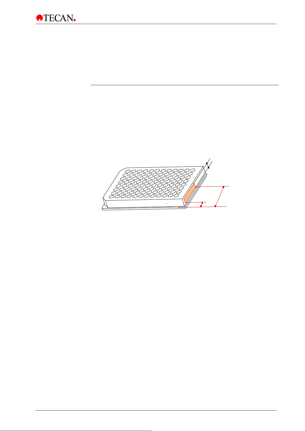
2.3.8 Microplates
Only 96-well format microplates (v-shaped, flat and round including strip-wells)
can be used with the Sunrise Absorbance Reader.
PARAMETERS CHARACTERISTICS
Max. overall plate height
Diameter of wells 9.0 mm (0.3543 inches)
Pitch size (center to center) 9.0 mm (0.3543 inches)
Bottom shape V-shaped, Flat and Round bottom
The barcode sticker has to be positioned on the right hand side of the plate,
7 mm from the front-right edge. The barcode may be up to 48 mm long.
14.35 mm ± 0.76 mm
(0.5650 inches ± 0.0299 inches)
6
1
55
7
The SUNRISE barcode reader supports the following barcode types:
• CODE 39
• Interleaved 2 of 5
• UPC A, UPC E0, UPC E1
• EAN8, EAN 13
• Codabar
• CODE 128
2003-12 Instructions For Use for SUNRISE Absorbance Reader No. I 137 311 Rev No. 1.0 2-11
Page 24

2. General
2.4 Instrument Description
The illustration below shows the components of the instruments.
Power ON LED
Plate Support
Lamp Compartment
Filter Block Compartment
2-12 Instructions For Use for SUNRISE Absorbance Reader No. I 137 311 Rev No. 1.0 2003-12
Page 25

2. General
2.4.1 Back Panel Connections
The illustration below shows the connections located in the back panel of the
instrument.
Barcode Laser Scanner Labels
(Only with t he Barcode Opti on)
Instruments Main Fuses
ON / OFF Switch
I
0
Mains Socket
Fuse Values
All connected devices must be approved and listed as per EN 60950, UL 1950 or
CSA C22.2 No. 950 for Data Processing Devices
Barcode Laser Scanner Labels
CAUTION
LASER RADIATION -
DO NOT STARE INTO BEAM
CLASS II LASER PRODUCT
Complies with 21CFR
and 1040.10 and 1040.11
Disconnect RS232 for local operation with Magellan CE
2 x F2A
Printer Connector
(Only function s with the Touchscre en option)
NICHT IN DEN STRAHL BLICKEN
RS 232
PRINTER
LASERSTRAHLUNG
LASER KLASSE 2
Leistun g: <1mW
Wellenl änge: 675nm
EN60825-1:1994+A11 :1996
Serial RS 232 Connector
TECAN
TYPE
Sunrise
ART.-NR.
F 0 3 9 3x x 1 1 0
SER.-NR.
xxxxx
VOLTAGE
AC 100 - 120 / 220 - 240
M-CODE
xxxxxx
TECAN
A-5082 AUSTRIA
VA
50 / 60
Hz
MADE IN
AUSTRIA
Three year s
warranty
TECAN
Label reproductions on the instrument housing and interior:
Note:
If any labels become damaged or removed, contact you local Tecan
2003-12 Instructions For Use for SUNRISE Absorbance Reader No. I 137 311 Rev No. 1.0 2-13
representative for replacement labels.
Page 26

2. General
2.4.2 Handling the Microplate
Insert or remove the microplate only when the plate support is fully ejected (as
illustrated below) and the plate transport motor is not active .
For details, see the corresponding Instructions for Use of the selected SW
product. (Magellan, MagellanCE, etc.)
WARNING
WHEN HANDLING THE MICROPLATE ALWAYS USE DISPOSABLE
GLOVES AND PROTECTIVE CLOTHING.
2-14 Instructions For Use for SUNRISE Absorbance Reader No. I 137 311 Rev No. 1.0 2003-12
Page 27

2. General
2.5 Filter Carriage Description
The SUNRISE instrument can use the following types of filter carriages:
SUNRISE Standard and SUNRISE Gradient Filter (with tuneable wavelength
option).
2.5.1 SUNRISE Standard Filter Carriage
The SUNRISE standard filter carriage has up to four narrow band interference
filters that have a fixed wavelength.
SUNRISE Standard Filter Carriage
4 3 2 1
When a wavelength is selected, the entered wavelength is compared against the
list of entered filter values for this filter carriage.
If the required filter is fitted in the filter carriage, the filter carriage is moved so that
the required filter is in the light beam.
Note:
For more information about the definition of the new and customized filter
slides, see 3.8 Defining the SUNRISE Instrument Settings.
2.5.2 SUNRISE Gradient Filter Carriage
SUNRISE Gradient filters cannot be used with a standard instrument.
The SUNRISE Gradient filter carriage is fitted with a gradient filter that allows the
selection of any wavelength from 400 to 700 nm.
Gradient Filter Carriage
Gradient Filter
Filter Positions
700 nm 400 nm
The Gradient filter carriages are calibrated by the manufacturer and each one is
unique.
When another Gradient filter is inserted into the instrument, the instrument
must be re-calibrated. This re-calibration procedure can only be performed
When a wavelength is selected, the entered wavelength is compared against the
calibration table. The filter carriage is moved the required distance, so that the
required section of the gradient filter is in the light beam.
Gradient filters cannot be used with the Standard SUNRISE Absorbance Reader.
2003-12 Instructions For Use for SUNRISE Absorbance Reader No. I 137 311 Rev No. 1.0 2-15
by the manufacturer or by a service engineer.
Note:
Page 28

2. General
2.5.3 SUNRISE 6 Filter Carriage
The SUNRISE 6 Filter carriage has up to six narrow band interference filters that
have a fixed wavelength.
Filter positions
1 2 3 4 5 6
When a wavelength is selected, the entered wavelength is compared against the
list of defined filter values for this filter carriage.
If the required filter is fitted in the filter carriage, the filter carriage is moved, so
that this specific filter is in the light beam.
Note:
For more information about the definition of the new and customized filter
slides, see 3.8 Defining the SUNRISE Instrument Settings.
2.6 Instrument Features
Microplates can be measured using the following features:
• Various measurement modes
• Single or dual wavelength measurements
• Microplate shaking
2.6.1 Measurement Modes
The instrument can be set to use the following measurement modes:
Normal The plate transport is moved quickly under the measurement
diodes so that a fast measurement is obtained. Each well is
measured at three points, 8 times for each point.
Accuracy The plate transport is moved very slowly under the measurement
diodes so that a very accurate measurement is obtained. Each well
is measured at three points, 55 times for each point.
Center This option measures the optical density only in the center of each
well. It is recommended for U-bottom wells or for liquids with high
meniscus. Each well is measured at one point, 22 times.
2-16 Instructions For Use for SUNRISE Absorbance Reader No. I 137 311 Rev No. 1.0 2003-12
Page 29

2. General
With the Normal and Accuracy measurement modes, the optical density is
measured at three positions across the wells and the average measured optical
density value from the three measurements is used as the optical density of the
well.
Note:
The accurate measurement cycle should always be used when measuring
The Center measurement mode should be used if the liquid in the microplate
produces a high meniscus, as an incorrect optical density could be obtained if the
optical density is measured at three positions. If an agglutination measurement is
performed, all the measurement positions are used.
For more information about setting the measurement mode,
see 3.8 Defining the SUNRISE Instrument Settings.
high optical densities.
Note:
2.6.2 Microplate Shaking
The SUNRISE is able to shake the microplate before it is measured. Use external
software (for example: Magellan) to set the shaking modes.
The microplate can also be shaken between each of the kinetic measurement
cycles.
WHEN USING A 96 WELL PLATE IN HIGH SHAKE MODE, SPILLAGE
MAY OCCUR IF THE WELLS ARE FILLED WITH MORE THAN 300 µL.
The shaking widths and frequencies for the 4 SUNRISE shake modes are as
follows:
Shake Mode Shake Width Shake Frequency
HIGH
NORMAL
LOW
WIDE
2.8 mm
4.4 mm
4.4 mm
14.2 mm
WARNING
12.3 Hz
9.2 Hz
7.8 Hz
2 Hz
2003-12 Instructions For Use for SUNRISE Absorbance Reader No. I 137 311 Rev No. 1.0 2-17
Page 30

2. General
2.7 Instrument Accessories
The table below contains the order numbers for instrument accessories:
Part Name Part Order Number
Halogen lamp................................................................................. 3 709 008
Reader to external computer cable................................................ 3 350 005
QC Pac 1 for SUNRISE ................................................................B 037 371
QC Pac 2 for SUNRISE ................................................................B 037 372
Additional filter slide (Standard 4-Filter)......................................... B 036 301
Memory card .............................................................................B 037 359 01
Flash card for Magellan Windows CE (English) ............................S 039 351
TS - Pen ......................................................................................... B 037 360
Barcode Upgrade Kit...................................................................... S 039 386
2.8 Software for the SUNRISE Absorbance Reader
Part of the Software CD:
Software Functionality
Magellan
XFluor4
SUNRISE Instrument Settings
Rdr Download
SunDiag
SUNRISE Absorbance Reader is intended for use with only external
For more information about the software features, see the appropriate
individual Instructions for Use. For example, refer to the Magellan
Reference Instructions for Use.
Instrument control and data reduction software.
(IVD version available, which has been declared
suitable for in-vitro diagnosis (IVD) purposes
(Directive 98/79/EC of the European
Community).
Instrument control and transfer of raw data to
Excel. (Not suitable for in-vitro diagnosis (IVD)
purposes)
Enables settings of SUNRISE instrument
(SUNRISE, SPECTRA, ATC mode, etc.).
Enables download of new firmware from PC to
reader.
For error diagnosis, a print out of the instrument
status for service purposes can be produced.
Note:
software.
Note:
2-18 Instructions For Use for SUNRISE Absorbance Reader No. I 137 311 Rev No. 1.0 2003-12
Page 31

3. Installation Procedure
3. Installation Procedure
3.1 Introduction
This chapter contains the necessary information for installing the instrument.
The installation procedures involve unpacking, environmental requirements,
power requirements and interfacing.
3.2 Unpacking and Inspection
The delivered instrument is shipped in one carton, which includes:
• Power cable
• Computer connection cable
• Instructions for Use for SUNRISE Absorbance Reader, XFluor4 Instructions
for Use
• Spare fuses
• A software CD, which also contains the XFluor4 program and Magellan demo
program (30 day working license).
Foam Packaging
Accessory box
Instrument
Foam
Packaging
2003-12 Instructions For Use for SUNRISE Absorbance Reader No. I 137 311 Rev No. 1.0 3-1
Page 32

3. Installation Procedure
3.3 Unpacking Procedure
1. Visually inspect the container for damage, before opening it.
Report any damage immediately.
2. Place the carton in an upright position and open it.
The cartridge, filter block and plate transport compartments are fixed with
adhesive tape. The location of the adhesive tape is indicated with a red
arrow.
3. Lift the instrument out of the carton and place it on a flat surface, free from
dust, vibration and away from direct sunlight.
4. Visually inspect the instrument for loose, bent or broken parts.
Report any damage immediately.
5. Compare the instrument's serial number, attached on the rear panel of the
instrument, against the serial number of the instrument, on the delivery
(shipping) note.
6. Check the instrument accessories against the delivery (shipping) note.
7. Open the plate support area cover and remove the foam strip that is used as
the microplate transport lock.
8. Please save all packing materials, as it may be required for storage or later
transportation.
3.4 Power Requirements
The instrument is auto sensing for the supplied voltage, and therefore does not
have to be set for the correct voltage.
Connect the instrument only to an electricity supply system with protective earth.
TO PREVENT THE RISK OF FIRE, THE MAINS FUSES SHOULD ONLY BE
REPLACED WITH THE SAME TYPE AND RATING OF FUSES.
WARNING
3-2 Instructions For Use for SUNRISE Absorbance Reader No. I 137 311 Rev No. 1.0 2003-12
Page 33

3. Installation Procedure
3.5 Environmental Requirements
The instrument should be placed on a flat, level surface that is free from dust,
solvents and acidic vapors.
Vibration and direct sunlight must be avoided, to ensure correct results.
Ambient Temperature:
Operation 15°C to 35°C (59°F to 95°F)
Storage -40°C to 60°C (-40°F to 140°F)
Relative Humidity:
Operation
Storage 5 % to 95 %
20 % to 90 %
3.6 Instrument Installation Procedure
The following procedures detail the necessary steps to be followed when
installing the instrument.
Caution
Before the instrument is installed and switched on, it should be left to
stand for at least three hours, so there is no possibility of condensation
When the requirements above have been met, installation is carried out using the
following procedure:
1. Place the instrument into the required position.
Ensure that the distance between the back panel of the instrument and the
wall is at least 10 cm.
2. Connect the instrument to the external computer with the required interfacing
cable.
The interfacing cable is connected into the 9 pin serial interface socket, in
the back panel.
3. Ensure that the mains power switch in the back panel of the instrument is in
the off position.
4. Insert the power cable into the mains power socket in the back panel.
5. Switch the instrument on using the mains power switch in the back panel and
wait for 15 minutes.
The instrument is now ready to measure microplates.
causing a short circuit.
3.7 Installation of Instrument Control Software
Note:
For more information about installing the software, see Magellan or
2003-12 Instructions For Use for SUNRISE Absorbance Reader No. I 137 311 Rev No. 1.0 3-3
XFluor4 Instructions for Use, which can be found on the Software CD.
Page 34

3. Installation Procedure
3.8 Defining the SUNRISE Instrument Settings
This program enables the user to define the settings of:
• Instrument modes
• Filter definition
• Measurement modes
Caution
If used in the IVD environment; only the authorized person is allowed to
change and define the SUNRISE Instrument Settings.
3.8.1 Installation of SUNRISE Instrument Settings Software
The SUNRISE Instrument Settings software is installed using the following
procedure:
1. Insert Tecan Detection Suite CD into the required CD ROM drive.
2. The Setup dialog box is displayed. Click the Service and Settings button.
Click the Setup button for the SUNRISE Instrument Settings. The installation
program is started, which installs SUNRISE Instrument Settings onto your
computer
3. A series of dialog boxes will appear, read each one, enter any necessary
information and click Next to continue.
4. The files are then installed and the program icon is created.
5. When the Installation Complete dialog box appears, click Finish and the
SUNRISE
Instrument Settings program is ready to be used.
3.8.2 Starting the SUNRISE Instrument Settings
In case an instrument is already connected to one of Tecan's programs, close the
program or disconnect the instrument.
The SUNRISE Instrument Settings software is started by clicking the SUNRISE
Instrument Settings icon on the desktop if present or go to Start – Programs –
Tecan – and select SUNRISE Instrument Settings.
The following dialog box appears:
In the SUNRISE Instrument Settings dialog box, select the communication port
and the baudrate. Click Next.
3-4 Instructions For Use for SUNRISE Absorbance Reader No. I 137 311 Rev No. 1.0 2003-12
Page 35

3. Installation Procedure
3.8.3 Define Instrument Mode
The following dialog box appears:
To use an instrument with software designed for previously manufactured Tecan
readers, select the appropriate instrument mode and baudrate. Click Next.
SUNRISE mode It is recommended to use the SUNRISE mode with 9600 baud.
Spectra mode Simulates a SPECTRA Reader.
Rainbow mode Simulates a Rainbow Reader
ATC mode Simulates an ATC Reader.
3.8.4 Define Filter
The following dialog box appears:
Click the Filterslide Out button to move the filter out of the instrument.
To insert a filter slide, open the filter compartment manually and slot the filter in
so that the filter end of the slide is inserted first. (Do not force the filter slide into
the instrument beyond the point of resistance).
Click the Filterslide In button and the filter is inserted.
2003-12 Instructions For Use for SUNRISE Absorbance Reader No. I 137 311 Rev No. 1.0 3-5
Page 36

3. Installation Procedure
Pos1 - 4 shows the filter values for the currently loaded absorbance filters.
Note:
The instrument is able to recognize predefined filter slides and you must
not attempt to change the filter values. However, if the filters in the filter
slide have been changed (by a service engineer) or if a new undefined
customized filter slide is to be used, the filter slides need to be defined.
To define the filter values for a new filter slide, enter the required wavelengths in
the text boxes. Click Next.
Note:
The wavelength range for the SUNRISE is 340 - 750 nm.
3.8.5 Define Measurement Mode
The following dialog box appears:
Select the appropriate measurement mode.
Click Next and the following dialog box appears:
These settings are not available to the SUNRISE Absorbance Reader.
3-6 Instructions For Use for SUNRISE Absorbance Reader No. I 137 311 Rev No. 1.0 2003-12
Page 37

3. Installation Procedure
Click Finish and the following dialog box appears:
The measurement mode has now been set successfully.
If the filter values for the new filter slide has been defined, then the following
dialog box appears at the end of the program.
2003-12 Instructions For Use for SUNRISE Absorbance Reader No. I 137 311 Rev No. 1.0 3-7
Page 38

Page 39

4. SUNRISE Touchscreen
4. SUNRISE Touchscreen
4.1 Introduction
The SUNRISE Touchscreen option consists of:
• A screen that includes a touch panel
• A Touchscreen pen
• Operating software MagellanCE
• SUNRISE Memo card
The Touchscreen option enables the user to control the reader and evaluates
obtained data, using the onboard software. The WindowsCE based software,
MagellanCE, offers the user the possibility for full instrument control, data
reduction and storage. It also supports numerous applications as ELISA's or
Kinetic studies. Enhanced curve fitting and screening tools, as well as the
possibility to combine several assays on one plate, makes it an ideal tool for
various laboratory purposes. The Touchscreen offers a clear and easy overview
of all available data.
The MagellanCE provides the user with Wizards for all operating procedures and
guides the user through the software program via step-by-step commands.
Disclaimer:
Magellan has been carefully devised and checked. With the exception of
negligence or intention, Tecan takes no liability for any damages that
occur as a result of the software.
Caution
If the instructions given in this manual are not correctly performed, the
instrument may be damaged or the procedure may not be correctly
performed and the safety of the instrument cannot be guaranteed.
Caution
Before the instrument is installed and switched on, it should be left to
stand for at least three hours, so there is no possibility of condensation
causing a short circuit.
Caution
Before starting measurements, make sure that the microplate position
A1 is inserted correctly.
Windows is registered trademark of the Microsoft Corporation.
2003-12 Instructions For Use for SUNRISE Absorbance Reader No. I 137 311 Rev No. 1.0 4-1
Page 40

4. SUNRISE Touchscreen
4.2 Area of Application for the Touchscreen Option
See 2.2 Area of Application.
4.3 Specifications
The table below lists the specifications for the Touchscreen.
PARAMETERS CHARACTERISTICS
Size
Operating System
Operating Software: MagellanCE
Storage
4.4 Instrument Description
The illustration below shows the components of the instrument.
240 x 320 pixel
WindowsCE
8 / 32 MB (SUNRISE Memo Card)
Touchscreen
SUNRISE MemoCard
Power On LED
Plate Support
Cartridge and Filter Block Compartment
4-2 Instructions For Use for SUNRISE Absorbance Reader No. I 137 311 Rev No. 1.0 2003-12
Lamp Compartment
Page 41

4. SUNRISE Touchscreen
4.4.1 Data Handling
The illustration below shows the concept of data handling of the instrument.
SUNRISE OPTION TOUCHSCREEN
SUNRISE MEMO CARD
TOUCH SCREEN
PORT COM 1
PARALLEL PORT
RS 232
TECAN
PORT COM 2
PC
PRINTER
The standard memory module for onboard operation is the SUNRISE memo card.
The SUNRISE memo card offers a capacity of 8 / 32 MB to save results and
defined methods. According to the size, between 300 / 1200 and 400 / 1600 files
can be stored permanently on the card. Additional cards can be ordered for
memory extension. Data can also be transferred to a PC either by transferring the
card to a PC and downloading the files or by using the data exchange module of
Magellan software (use of this module requires no license.)
This module enables the user to exchange data between the reader and a
connected PC via the RS232 port (COM1).
Additionally, the SUNRISE can be connected to the personal computer (PC) and
by-pass the onboard software (Port COM 2).
2003-12 Instructions For Use for SUNRISE Absorbance Reader No. I 137 311 Rev No. 1.0 4-3
Page 42

4. SUNRISE Touchscreen
4.4.2 Printer Compatibility
The SUNRISE Touchscreen supports the following industry standard printer
languages:
1. Hewlett-Packard PCL3 Compatible devices
2. Epson ESC/P2 Compatible devices
Not only Hewlett-Packard printers support PCL3, but also the majority of the laser
printers. Please contact your printer provider or look up the printer specifications
on the Internet homepage of the printer manufacturer for further information.
Please note:
Printer languages up to PCL5E are compatible with PCL3. PCL6 is not
longer compatible with PCL3.
For example, the SUNRISE Touchscreen supports the following printers:
For further information see the Hewlett-Packard homepage.
Hewlett-Packard
Deskjet
Hewlett-Packard
Laserjet
Epson Stylus Color 400, 600, 740, 750, 800, & 900 series
Epson Stylus Photo & Photo 700
Canon Bubblejet 30, 50, 70, 80, 250, 1000, 2000, 4300, 4400
300, 400, 500, 600, 660, 672, 680, 690, 870, 880 895, 340C, 350C, 640C,
840C, 930C, 950C, 970 CXI, 990 CXI
4L, 4P, 4M, 4MP, 4si, 5L, 5P, 5M, 5MP, 5si, 6L, 6P, 6MP, 4000
4-4 Instructions For Use for SUNRISE Absorbance Reader No. I 137 311 Rev No. 1.0 2003-12
Page 43

4. SUNRISE Touchscreen
4.5 Operating the Touchscreen
4.5.1 Introduction
The Touchscreen can be operated either by simply touching the touch panel with
the finger or using the Touchscreen pen, which is included in the package.
Some of the functions on the touch panel are rather small, so it is
Before starting measurements, make sure that the microplate position
recommended to use the Touchscreen pen.
Caution
A1 is inserted correctly.
Note:
4.5.2 Starting the Software
• Make sure that the SUNRISE Memo card is inserted in the Touchscreen.
• Switch the instrument on.
• The Wizard and a keyboard are displayed on the touch panel. The
keyboard is always displayed. When it is not required, it can be shifted to
the side of the panel with the Touchscreen pen or with a finger.
• The Wizard structure guides the user through every step. The starter
screen is displayed:
2003-12 Instructions For Use for SUNRISE Absorbance Reader No. I 137 311 Rev No. 1.0 4-5
Page 44

4. SUNRISE Touchscreen
4.5.3 Special Features of MagellanCE
Input Panel
Some Input Panel keys have special functions:
Date / Time
Caps lock key
selected
Caps key selected
Caps lock
and Caps key
selected
Caps lock
and Caps key
not selected
Special characters key
Esc key Click to close the current window.
In the Wizard List dialog box under Other Wizards, select Options.
The Global Settings dialog box is made up of 5 tabs:
Export, Workspace Name, User Administration, Date and Time
and Misc.
Click to view the capital character keys.
All letters will be capitalized.
The first letter typed will be in capitals, the following
letters will be in lowercase.
The first letter typed will be in lowercase, the following
letters will be in capitals.
All letters will be in lowercase.
Click to view the special character keys.
To set the date and time, select the Date and Time tab.
Enter the current date and time and click Apply.
4-6 Instructions For Use for SUNRISE Absorbance Reader No. I 137 311 Rev No. 1.0 2003-12
Page 45

4. SUNRISE Touchscreen
Exit to Recalibrate screen
The Touchscreen can be recalibrated, if the screen is not responding properly to
the Touchscreen pen. Select Exit to Recalibrate screen from the Settings menu
and follow the instructions. The program will be exited and restarted.
2003-12 Instructions For Use for SUNRISE Absorbance Reader No. I 137 311 Rev No. 1.0 4-7
Page 46

Page 47

5. Error Messages and Trouble Shooting
5. Error Messages and Trouble
Shooting
5.1 Introduction
The internal microprocessor controls and checks all electronic functions as well
as measurements, operations and results. If the microprocessor detects a fault or
an incorrect operating procedure, an error message is displayed on the computer.
5.1.1 Table of Error Messages and Trouble Shooting for
SUNRISE Mode
The following table gives a brief description of the error messages and the trouble
shooting actions.
Error Message
System Errors
Out of memory in module…
Not implemented
Timer event not active
Note:
If other error messages appear that are not mentioned in the table below,
contact your local service engineer.
Description Trouble Shooting
Internal firmware error Switch instrument off and then on
again. Contact your local service
engineer, if the error continues.
Internal firmware error Switch instrument off and then on
again. Contact your local service
engineer, if the error continues.
Internal firmware error Switch instrument off and then on
again. Contact your local service
engineer, if the error continues.
2003-12 Instructions For Use for SUNRISE Absorbance Reader No. I 137 311 Rev No. 1.0 5-1
Page 48

5. Error Messages and Trouble Shooting
Error Messages
Wrong Transport Positioning
Transport lost steps due to invalid
shaking section
Transport lost …. steps
Transport inserted steps
Transport lost steps during calibration
Description Trouble Shooting
Transport Check that the microplate is
inserted correctly and nothing is
blocking the transport system.
Contact your local service engineer,
if the error continues.
Wrong detection
of the positioning
switches.
Check that the microplate is
inserted correctly and nothing is
blocking the transport system.
Contact your local service engineer,
if the error continues.
Wrong detection
of the positioning
switches.
Check that the microplate is
inserted correctly and nothing is
blocking the transport system.
Contact your local service engineer,
if the error continues.
Wrong detection
of the positioning
switches.
Check that the microplate is
inserted correctly and nothing is
blocking the transport system.
Contact your local service engineer,
if the error continues.
Wrong Transport Parameters
Transport frequency too low
Transport frequency too high
Optical Problems
Transport couldn't find full dark edge
during calibration
Lamp low
Timeout waiting for lamp on
Timeout waiting for measurement
finished
Software error Wrong combination of selected
measurement parameters.
Software error Wrong combination of selected
measurement parameters.
Lamp or other
optical defect
Check lamp and if the lamp is
working and positioned correctly,
contact your local service engineer.
The optical
system is
receiving not
Check lamp and if the lamp is
working and positioned correctly,
contact your local service engineer.
enough light
Lamp or other
optical defect
Check lamp and if the lamp is
working and positioned correctly,
contact your local service engineer.
Lamp or other
optical defect
Check lamp and if the lamp is
working and positioned correctly,
contact your local service engineer.
5-2 Instructions For Use for SUNRISE Absorbance Reader No. I 137 311 Rev No. 1.0 2003-12
Page 49

5. Error Messages and Trouble Shooting
Error Messages
Filter Errors
Already inserted
No filter carriage detected
No measurement filter
defined
No reference filter defined
Illegal filter carriage
position
Wavelength … nm not
available
Filter carriage not
defined, Type.. Number…
Description Trouble Shooting
Filter already inserted Check if the filter is properly inserted.
The instrument does not
detect the filter carriage
Insert filter. If a filter has been already
inserted, check the filter carriage for
dirt or damage. Contact your local
service engineer, if the error
continues.
The measurement filter is
Define filter.
not defined
The reference filter is not
Define filter.
defined
Internal firmware or
electrical error
Check the filter carriage for dirt or
damage. Contact your local service
engineer, if the error continues.
The defined reference or
measurement filter is not
Change filter carriage or check filter
values for incorrect input.
available on the inserted
filter carriage
Wrong, damaged or not
defined filter carriage
inserted
Check the filter carriage to see if it is
correct or check the filter carriage for
dirt and damage.
ADC Electronic Error
Offset 340 not adjusted Electronic error on ADC
board or optical problem
Offset 400 not adjusted Electronic error on ADC
board or optical problem
No wavelength defined Electronic error on ADC
board or optical problem
Area 400 not adjusted Electronic error on ADC
board or optical problem
Area 340 not adjusted Electronic error on ADC
board or optical problem
E2Pot Overflow Electronic error on ADC
board or optical problem
Start Lamp Adjust program in the
Setup program. Contact your local
service engineer, if the error continues.
Start Lamp Adjust program in the
Setup program. Contact your local
service engineer, if the error continues.
Start Lamp Adjust program in the
Setup program. Contact your local
service engineer, if the error continues.
Start Lamp Adjust program in the
Setup program. Contact your local
service engineer, if the error continues.
Start Lamp Adjust program in the
Setup program. Contact your local
service engineer, if the error continues.
Start Lamp Adjust program in the
Setup program. Contact your local
service engineer, if the error continues.
2003-12 Instructions For Use for SUNRISE Absorbance Reader No. I 137 311 Rev No. 1.0 5-3
Page 50

5. Error Messages and Trouble Shooting
5.1.2 Table of Error Messages and Trouble Shooting for
SPECTRA Mode
Error Messages
Filter
Transport
Lamp low
Lamp high
System
Abort
Description Trouble Shooting
The filter slide has not
reached the required
position or is not defined.
Microplate transport error Ensure that the microplate is inserted
Optical system error This message is displayed when the
Optical system error This message is displayed when the
Internal firmware or flash
EPROM error
Lamp or other optical defect Check lamp and if the lamp is working and
Check that the filter slide is correctly inserted
into the instrument. Contact your local
service engineer, if the error continues.
correctly and that nothing is blocking the
transport system. Contact your local service
engineer, if the error continues.
instrument detects that the optical system is
not receiving enough light. Possible causes
could be: defective halogen lamp, halogen
lamp incorrectly positioned, optical system is
not clean, filter alignment out of range.
Contact your local service engineer, if the
error continues.
instrument detects that the optical system is
receiving too much light. Possible causes
could be: defective halogen lamp, halogen
lamp incorrectly positioned. Contact your
local service engineer, if the error continues.
Contact your local service engineer.
positioned correctly, contact your local
service engineer.
5-4 Instructions For Use for SUNRISE Absorbance Reader No. I 137 311 Rev No. 1.0 2003-12
Page 51

6. Maintenance & Cleaning
6. Maintenance & Cleaning
6.1 Introduction
This chapter contains the following procedures on how to:
• Replace the lamp
• Replace the filter carriages
• Replace the mains input fuses
• Clean the instrument
• Disinfect the instrument
WARNING
REMOVE THE MICROPLATE BEFORE DOING ANY MAINTENANCE.
6.2 Lamp Replacement
The instrument specifications can only be guaranteed if genuine Tecan
The following steps must be followed to replace the lamp:
Before starting to replace the lamp leave the instrument to cool down for at least
thirty minutes.
1. Switch off the instrument and disconnect it from the mains supply.
Note:
parts are used.
2003-12 Instructions For Use for SUNRISE Absorbance Reader No. I 137 311 Rev No. 1.0 6-1
Lamp Compartment
Page 52

6. Maintenance & Cleaning
2. Remove the lamp compartment cover by gently pulling it from the underside.
3. Push the locating spring bar, on top of the lamp, to the left.
4. Carefully remove the lamp from the lamp holder.
WARNING
TO PREVENT BURNS, ENSURE THAT THE LAMP IS COLD.
5. Disconnect the lamp power cables from the lamp power connector.
6. Replace the old lamp.
7. Reconnect the lamp power connector.
8. Replace the lamp into the lamp holder.
Please note that the lamp is held in place by three lugs, between which the lamp
is to be inserted.
Insert the lamp so that the cables are at the bottom.
Locating Lugs
Lamp
Spring bar
Connecting Plug
10. Lock the lamp into place using the spring bar.
11. Before closing the cover plate, ensure, that the lamp is properly seated, in
the three lugs.
12. Close the lamp compartment cover.
Caution
Do not touch the reflective surface and the bulb. Any fingerprints on
these surfaces must be removed with acetone or methylated spirits.
6-2 Instructions For Use for SUNRISE Absorbance Reader No. I 137 311 Rev No. 1.0 2003-12
Page 53

6. Maintenance & Cleaning
6.3 Filter Replacement
6.3.1 Standard Filter Carriages
The filters of the standard filter carriages can be replaced using the following
procedure:
1. Remove the filter carriage from the instrument.
2. Place the filter carriage on a clean flat surface.
Filter
Positions
1 2 3 4
3. Using a wooden or rubber rod (ensure that the ends are rounded so that the
corners do not scratch the filters) carefully push the filter and retaining ring
out of the filter carriage.
Rod
Filters
Retaining Rings
4. Turn the filter carriage over and insert the new filter and the retaining ring.
5. Carefully push the filter and retaining ring into the filter carriage, using a
wooden or rubber rod.
Caution
When handling the filters, be careful that they do not become
scratched or soiled with fingerprints or dust.
2003-12 Instructions For Use for SUNRISE Absorbance Reader No. I 137 311 Rev No. 1.0 6-3
Page 54

6. Maintenance & Cleaning
6.3.2 Gradient Filter Carriages
Note:
The instrument specifications can only be guaranteed if genuine Tecan
Using the option tuneable wavelength selection, the instrument is fitted with a
special gradient filter, which allows the selection of any wavelength of light
between 400 and 700 nm. For measurements in the ranges of 340 - 399 nm and
700 - 750 nm the appropriate Standard filter carriage, containing the required
wavelength filters, must be inserted into the instrument.
The filter carriage can be exchanged for another carriage, which contains other
filters; the instrument can store the data for up to eight filter carriages.
To change the filter carriage, please follow the procedure outlined in the
appropriate software Instructions for Use.
parts are used.
6.3.3 6 Filter Carriages
The filters of the standard filter carriages can be replaced using the following
procedure:
To replace all of the filters:
1. Remove the filter carriage from the instrument.
2. Place the filter carriage on a clean flat surface, so that the Philips head
screws are visible.
Filter positions
1 2 3 4 5 6
3. Remove the two screws and then remove the retaining bar that holds the
retaining pins.
4. Remove the filters. Be careful not to scratch the filters or soil them with
fingerprints or dust.
5. Insert the new filters and replace the retaining bar. Replace and tighten the
screws.
6-4 Instructions For Use for SUNRISE Absorbance Reader No. I 137 311 Rev No. 1.0 2003-12
Page 55

6. Maintenance & Cleaning
To replace a single filter:
1. Follow steps 1 and 2 above.
2. Remove the retaining pin of the filter to be replaced with needle-nose
pliers.
3. Remove the filter. Be careful not to scratch it or soil it with fingerprints or
dust.
4. Insert the new filter and replace the retaining pin.
6.4 Fuse Replacement
The following steps must be performed to replace the fuse, which is located
above the power cable connection, in the rear panel of the instrument.
TO PREVENT THE RISK OF FIRE, THE MAINS FUSES SHOULD ONLY BE
REPLACED WITH THE SAME TYPE AND RATING OF FUSES.
WARNING
1. Switch off the instrument and unplug the power cord.
2. Open the plastic cover of the fuse compartment, by inserting a screw driver
into the slot in the top of the cover and pushing the cover out.
3. The fuse holders are located above the on/off switch.
Fuse
-
4. Pull the fuse holder(s) out and replace the defective fuse(s) with the spare
fuse(s).
Ensure that the fuse(s) has/have the correct rating.
F 2.0 A / 250 V (Fast Blow)
5. Replace the fuse holder(s), ensure that the arrow points in the correct
direction and close plastic cover of the fuse compartment.
6. Reconnect the power cord and switch the instrument on
Holders
0
WARNING
IF THE FUSE CONTINUES TO BLOW, PLEASE CALL FOR SERVICE.
2003-12 Instructions For Use for SUNRISE Absorbance Reader No. I 137 311 Rev No. 1.0 6-5
Page 56

6. Maintenance & Cleaning
6.5 Cleaning the Instrument
Liquid Spills
If any liquid is spilled in the instrument, it should be immediately removed to
prevent liquid running into the optical system and causing a loss of accuracy or
the error message Lamp Low due to one or more of the diode lenses not being
clean.
Cleaning the Touchscreen
The Touchscreen may be cleaned periodically using a tissue moistened with a
mild detergent solution.
6.6 Preventive Maintenance Plan for SUNRISE
This preventive maintenance plan is for standard throughput instruments. For
instruments that are used in high throughput, the maintenance intervals are
maybe shorter.
6.6.1 Daily
• No daily maintenance is required.
6.6.2 Weekly
• Clean the cover and the plate transport with a mild detergent.
Caution
Never use Acetone as it will damage the covers.
6.6.3 Every Six Months
• Clean the filters using a optical cleaning solution.
(Lens tissue recommended)
6.6.4 Yearly (Service Engineer Required)
• Check the lamp and mirror unit.
• Check if diode counts are in the necessary range.
• Start Position test.
• Perform duration test for about 100 cycles.
• Perform the QC Pac 2 test (see QC Pac 2 Instructions for Use).
6.6.5 Every Four Years
• Replace the lamp and the filters.
6-6 Instructions For Use for SUNRISE Absorbance Reader No. I 137 311 Rev No. 1.0 2003-12
Page 57

6. Maintenance & Cleaning
6.7 Instrument Disinfection
All parts of the instrument that come into contact with the patient sera or positive
control samples must be treated as potentially infectious areas.
It is advisable to wear gloves when performing the measurement
procedure and also when making adjustments to the instrument.
It is very important that the instrument is thoroughly disinfected before it is
removed from the laboratory or any servicing is performed on it.
Before the instrument is returned to the distributor for servicing, it must be
disinfected and a disinfection certificate completed by the operating authority. If a
disinfection certificate is not supplied, the instrument may not be accepted by the
servicing center or it may be held by the customs authorities.
Note:
6.7.1 Disinfection Procedure
If the laboratory has no specific disinfection procedure, the following procedure
should be used to disinfect the instrument.
The instrument should be disinfected using one of the following solutions:
Lysetol Manufacturer: Schülke & Mayr Ges.m.b.H.
Aseptisol Manufacturer: Bode Chemie Hamburg
If neither of these solutions are available 70% ethanol should be used as an
alternative.
THE DISINFECTION PROCEDURE SHOULD BE PERFORMED BY
AUTHORIZED TRAINED PERSONNEL IN A WELL VENTILATED ROOM
WEARING DISPOSABLE GLOVES AND PROTECTIVE GLASSES AND
The disinfectant can negatively influence the performance of your
instrument, if it is applied inside the instrument.
WARNING
CLOTHING.
Caution:
2003-12 Instructions For Use for SUNRISE Absorbance Reader No. I 137 311 Rev No. 1.0 6-7
Page 58

6. Maintenance & Cleaning
The following procedure should be used to disinfect the instrument.
1. Wear protective gloves, protective glasses and protective clothing.
2. Prepare an autoclaveable bag for all disposables used during the
disinfection procedure and label it with autoclave tape.
3. Disconnect the instrument from the mains power supply to avoid any risk of
explosion.
4. Disconnect the instrument from the computer.
5. Carefully spray the disinfectant solution (or use a disposable soft tissue
paper towel soaked in the disinfectant) on all outer surfaces of the
instrument.
6. After a minimum contact time of 10 minutes, repeat the previous step of this
procedure.
7. After a contact time of five hours wipe the instrument using a soft paper
towel and a mild detergent or distilled water to remove all traces of the
disinfectant.
8. Wipe dry the outer surfaces of the instrument.
9. Pack the instrument and its accessories.
10. Disinfect your hands and clean them with a mild detergent.
11. Complete a disinfection declaration and attach it to the outside of the
box so that it is clearly visible. See below for an example of the
disinfection declaration.
See below for an example of the disinfection declaration, which must be
completed before the instrument is returned to the distributor for servicing.
6.8 Disinfection Declaration
The following label MUST be completed by the operating authority and attached
to the top of the package in which the instrument is returned, before sending the
instrument to the servicing center for repair.
I declare that the instrument in this package has been decontaminated or
disinfected to remove or inactivate any biological material, which could be
dangerous to the service personnel, or that it has never been exposed to
any hazardous biological material.
Name:...................................................................................................................
Firm: .....................................................................................................................
Address: ...............................................................................................................
.............................................................................................................................
.............................................................................................................................
Country:................................................................................................................
Signature:.............................................................................................................
6-8 Instructions For Use for SUNRISE Absorbance Reader No. I 137 311 Rev No. 1.0 2003-12
Page 59

6. Maintenance & Cleaning
6.9 Disposal of Instrument
6.9.1 Introduction
Follow laboratory procedures for biohazardous waste disposal, according to
national and local regulations.
This chapter gives instructions on how to lawfully dispose of waste material
accumulating in connection with the Sunrise.
Observe all federal, state and local environmental regulations.
6.9.2 Disposal of Packing Material
According to Directive 94/62/EC on packaging and packaging waste, the
manufacturer is responsible for the disposal of packing material.
Caution
Returning Packing Material
If you do not intend to keep the packing material for future use, e.g. for transport
and storage purposes:
Return the packaging of the product, spare parts and options via the field service
engineer to the manufacturer.
6.9.3 Disposal of Operating Material
WARNING
BIOLOGICAL HAZARDS CAN BE ASSOCIATED WITH THE WASTE
OF THE PROCESS RUN ON THE SUNRISE ABSORBANCE READER.
TREAT THE USED MICROPLATE, OTHER DISPOSABLES, AND ALL
SUBSTANCES USED, IN ACCORDANCE WITH GOOD LABORATORY
INQUIRE ABOUT APPROPRIATE COLLECTING POINTS AND APPROVED
METHODS OF DISPOSAL IN YOUR COUNTRY, STATE OR REGION.
MATERIAL (MICROPLATE) .
PRACTICE GUIDELINES.
2003-12 Instructions For Use for SUNRISE Absorbance Reader No. I 137 311 Rev No. 1.0 6-9
Page 60

6. Maintenance & Cleaning
6.9.4 Disposal of the Sunrise Instrument
Please contact your local Tecan Service representative before disposing of the
instrument.
Caution
Always disinfect the instrument before disposal.
Pollution degree
Method of Disposal
2 (IEC/EN 61010-1)
Contaminated Waste
WARNING
DEPENDING ON THE APPLICATIONS, PARTS OF THE SUNRISE MAY
HAVE BEEN IN CONTACT WITH BIOHAZARDOUS MATERIAL.
● MAKE SURE TO TREAT THIS MATERIAL ACCORDING TO THE
APPLICABLE SAFETY STANDARDS AND REGULATIONS.
● ALWAYS DECONTAMINATE ALL PARTS BEFORE DISPOSAL.
6-10 Instructions For Use for SUNRISE Absorbance Reader No. I 137 311 Rev No. 1.0 2003-12
Page 61

7. Performance Testing / Quality Control
7. Performance Testing / Quality
Control
7.1 Introduction
Caution
If at any time the analytical performance of the SUNRISE is questioned
the user should follow the instructions given for quality control or
Before starting measurements, make sure that the microplate position
contact the local service center.
Caution
A1 is inserted correctly.
This chapter gives the instructions on how to obtain the best performance and
accuracy from this instrument.
Also included are instructions on how to easily check the performance of the
instrument.
7.2 Optimizing for Maximum Performance
The instrument has been fully factory tested to ensure that it's performance is
within the specified limits.
It has been found through experience that operating technique and laboratory
conditions cause the greatest amount of inaccuracy.
The greatest accuracy can be obtained from the instrument by observing the
recommendations below:
7.2.1 Instrument Location
The instrument should be placed on a level, flat surface that is free from dust,
solvents and acidic vapors.
The instrument must be protected from vibrations and direct light, particularly
sunlight.
When performing the measurements, always close the plate support cover to
ensure that the results are not effected by any external light.
2003-12 Instructions For Use for SUNRISE Absorbance Reader No. I 137 311 Rev No. 1.0 7-1
Page 62

7. Performance Testing / Quality Control
7.2.2 Operating Procedure
General
1. The best repeatability is obtained, when the measurement wavelength
corresponds to the maximum absorbance wavelength of the particular
solution.
It is important to use the maximum absorbance wavelength, if the
absorbance curve of the sample is over a narrow wavelength band.
2. After each microplate has been measured, please refer to the Test Kit
package for information regarding the validation procedure.
3. When very accurate results are required, ensure the Accurate measurement
mode is used.
Microplates
1. The instrument can be used with any type of microplate. The best results are
obtained when a clear flat-bottom microplates are used in the specifications.
Depending on the type of microplate being used, the measurement result
may vary.
Take care especially when using round bottom plates or the strip
frames because it is possible that the measurement results might differ
slightly to that what is described in the specifications.
Make sure that the type of microplate used with the Sunrise Absorbance
Reader is suitable for the respective application. This applies particularly to
IVD applications.
2. Use only perfectly clean microplates.
3. Do not allow dust to settle onto the solutions or the microplate, if the
microplate is left to stand for a time before the measurement.
4. Inaccuracies in the amount of solution pipetted has a greater effect on the
results obtained, when small amounts of solutions are used.
It is recommended that a minimum of 200 microliters is used in each well.
5. The form of the meniscus of the solution can cause inaccuracies in the
results, particularly if small amounts of solution are used.
Make sure the suitability of the microplate used in combination with the
amount of solution, meniscus properties and the measurement mode is
appropriate for the current application. This is especially necessary
when performing measurements for IVD applications.
7.2.3 Self Check Procedure
Before each microplate is measured, the Self Check calibration procedure is
performed to ensure that the instrument is working correctly and to calibrate the
optical system.
When the Self Check procedure starts, a digital value for each measurement
channel is taken without the lamp and with the lamp on, using each of the
selected measurement filters.
A calibration curve for each measurement channel is calculated.
Caution
7-2 Instructions For Use for SUNRISE Absorbance Reader No. I 137 311 Rev No. 1.0 2003-12
Page 63

7. Performance Testing / Quality Control
7.3 Performance Tests
The following test can be done to ensure that the instrument is working correctly
and accurate results are being obtained.
The repeatability and accuracy of the instrument may vary with the type of
solution and microplate used.
To eliminate this effect, the instruments are tested in the factory with a calibration
plate, which removes the influence of the solution and any variation due to the
positioning of the microplate when it is being measured.
7.3.1 QC PAC 2
QC PAC 2 provides an automated check of reader performance including
accuracy, linearity, precision and alignment with NIST traceable standards. It also
detects damaged or mislabeled filters. For more information, see QC PAC 2
Instructions for Use.
Only use QC PAC 2 for SUNRISE instruments. The former version of the
QC PAC 2 (for SPECTRA instruments) is not compatible with the
7.3.2 Microplate Test
If the optical densities of the wells in the microplate are not consistent, the results
obtained with this type of microplate will be influenced.
This inconsistency can be checked by reading an empty microplate.
The OD values obtained from the measurement of the empty microplate should
be in a narrow range. For example: +/- 0.010 OD.
If the OD values are not within this range this type of microplate should not be
used.
By using dual wavelength measurements, the influence of the difference in OD
values of the microplate is removed or reduced to a level that is within acceptable
limits.
Caution
instrument.
2003-12 Instructions For Use for SUNRISE Absorbance Reader No. I 137 311 Rev No. 1.0 7-3
Page 64

7. Performance Testing / Quality Control
Acceptable Microplate
1 2 3 4 5 6 7 8 9 10 11 12
-------|-------|-------|-------|-------|-------|-------|-------|-------|-------|-------|-------
|
A | 0.042 | 0.039 | 0.045 | 0.041 | 0.039 | 0.037 | 0.043 | 0.043 | 0.040 | 0.039 | 0.043 | 0.041 | A
|-------|-------|-------|-------|-------|-------|-------|-------|-------|-------|-------|-------|
B | 0.042 | 0.042 | 0.040 | 0.040 | 0.042 | 0.040 | 0.045 | 0.043 | 0.039 | 0.038 | 0.043 | 0.039 | B
|-------|-------|-------|-------|-------|-------|-------|-------|-------|-------|-------|-------|
C | 0.043 | 0.040 | 0.040 | 0.043 | 0.041 | 0.041 | 0.042 | 0.042 | 0.041 | 0.046 | 0.043 | 0.039 | C
|-------|-------|-------|-------|-------|-------|-------|-------|-------|-------|-------|-------|
D | 0.043 | 0.043 | 0.047 | 0.038 | 0.039 | 0.040 | 0.040 | 0.041 | 0.042 | 0.039 | 0.039 | 0.049 | D
|-------|-------|-------|-------|-------|-------|-------|-------|-------|-------|-------|-------|
E | 0.041 | 0.044 | 0.046 | 0.043 | 0.039 | 0.040 | 0.040 | 0.042 | 0.043 | 0.041 | 0.045 | 0.044 | E
|-------|-------|-------|-------|-------|-------|-------|-------|-------|-------|-------|-------|
F | 0.046 | 0.042 | 0.041 | 0.043 | 0.042 | 0.052 | 0.043 | 0.047 | 0.045 | 0.044 | 0.041 | 0.040 | F
|-------|-------|-------|-------|-------|-------|-------|-------|-------|-------|-------|-------|
G | 0.041 | 0.043 | 0.041 | 0.040 | 0.042 | 0.042 | 0.041 | 0.040 | 0.043 | 0.043 | 0.041 | 0.041 | G
|-------|-------|-------|-------|-------|-------|-------|-------|-------|-------|-------|-------|
H | 0.042 | 0.040 | 0.040 | 0.044 | 0.045 | 0.039 | 0.041 | 0.046 | 0.045 | 0.044 | 0.040 | 0.045 | H
|
-------|-------|-------|-------|-------|-------|-------|-------|-------|-------|-------|-------
1 2 3 4 5 6 7 8 9 10 11 12
|
|
Unacceptable Microplate
1 2 3 4 5 6 7 8 9 10 11 12
-------|-------|-------|-------|-------|-------|-------|-------|-------|-------|-------|-------
|
A | 0.104 | 0.105 | 0.110 | 0.134 | 0.136 | 0.168 | 0.147 | 0.140 | 0.163 | 0.154 | 0.167 | 0.188 | A
|-------|-------|-------|-------|-------|-------|-------|-------|-------|-------|-------|-------|
B | 0.119 | 0.107 | 0.110 | 0.151 | 0.133 | 0.168 | 0.153 | 0.138 | 0.165 | 0.167 | 0.167 | 0.178 | B
|-------|-------|-------|-------|-------|-------|-------|-------|-------|-------|-------|-------|
C | 0.111 | 0.117 | 0.121 | 0.141 | 0.146 | 0.136 | 0.156 | 0.150 | 0.158 | 0.173 | 0.170 | 0.182 | C
|-------|-------|-------|-------|-------|-------|-------|-------|-------|-------|-------|-------|
D | 0.112 | 0.101 | 0.113 | 0.153 | 0.146 | 0.127 | 0.139 | 0.143 | 0.152 | 0.165 | 0.163 | 0.170 | D
|-------|-------|-------|-------|-------|-------|-------|-------|-------|-------|-------|-------|
E | 0.105 | 0.109 | 0.114 | 0.135 | 0.120 | 0.131 | 0.142 | 0.138 | 0.143 | 0.161 | 0.163 | 0.163 | E
|-------|-------|-------|-------|-------|-------|-------|-------|-------|-------|-------|-------|
F | 0.096 | 0.106 | 0.110 | 0.138 | 0.132 | 0.128 | 0.128 | 0.149 | 0.158 | 0.155 | 0.161 | 0.172 | F
|-------|-------|-------|-------|-------|-------|-------|-------|-------|-------|-------|-------|
G | 0.097 | 0.110 | 0.112 | 0.125 | 0.133 | 0.125 | 0.120 | 0.132 | 0.145 | 0.155 | 0.168 | 0.156 | G
|-------|-------|-------|-------|-------|-------|-------|-------|-------|-------|-------|-------|
H | 0.095 | 0.090 | 0.096 | 0.144 | 0.129 | 0.124 | 0.129 | 0.139 | 0.131 | 0.150 | 0.151 | 0.161 | H
|
-------|-------|-------|-------|-------|-------|-------|-------|-------|-------|-------|-------
1 2 3 4 5 6 7 8 9 10 11 12
|
|
7-4 Instructions For Use for SUNRISE Absorbance Reader No. I 137 311 Rev No. 1.0 2003-12
Page 65

7. Performance Testing / Quality Control
7.3.3 High Meniscus Liquids
When measuring liquids that produce a high meniscus, the measured optical
density can be incorrect as the instrument normally measures the optical density
at three positions in the well and uses this average measured optical density as
the optical density for the well.
Normal Mode
3 positions, 8 measurements per position.
Positions are 0.4375 mm apart.
Accuracy Mode
3 positions, 55 measurements per position.
Positions are 0.4375 mm apart.
Normal meniscus High meniscus
Center Mode
1 position, 22 measurements.
Normal meniscus High meniscus
2003-12 Instructions For Use for SUNRISE Absorbance Reader No. I 137 311 Rev No. 1.0 7-5
Page 66

7. Performance Testing / Quality Control
Agglutination Method
For agglutination measurements, an external software package such as Software
2000 must be used. Depending on the software used, the SUNRISE Absorbance
Reader must be set to SUNRISE or SPECTRA mode using the SUNRISE
Instrument Settings software. The SUNRISE Absorbance Reader is able to read
up to 40 measurement points per well.
Note:
Instruments with option tuneable wavelength selection are not able to
After the microplate has been measured, select a well and zoom it so that it is
printed in large scale.
Normal Liquid Liquid with High Meniscus
100%
RRCC
perform agglutination measurements.
100%
100%
RRCC
100%
50%
0%
1
10 20 30 40
Measurement
50%
0%
50%
0%
1
10 20 30 40
Measurement
50%
0%
If the printout has less than sixteen measurement points in the middle of the well,
that are at the same level, use the center measurement.
7-6 Instructions For Use for SUNRISE Absorbance Reader No. I 137 311 Rev No. 1.0 2003-12
Page 67

7. Performance Testing / Quality Control
Manual Method
If the instrument is not able to perform Agglutination measurements, measure the
microplate five times.
Then rotate the microplate by 180 ° and then measure the microplate five times.
For a number of wells, calculate the average optical density value from all the
measurements for these wells.
Compare the average value against the highest and lowest measured values.
Example
Measured Values
0.945, 0.956, 0.937, 0.926, 0.971, 0.936, 0.961, 0.939, 0.942, 0.938
Average = 0.945, Highest = 0.971, Lowest = 0.926
Tolerances = (0.945 ± 0.5 % and ± 0.005)
Highest value within tolerance = 0.955
Lowest value within tolerance = 0.935
Ensure that the values are within the allowed tolerances, if not use the Center
measurement mode.
Repeat the procedure using the Center measurement, to ensure that the
measured values are now within the required tolerances.
2003-12 Instructions For Use for SUNRISE Absorbance Reader No. I 137 311 Rev No. 1.0 7-7
Page 68

7. Performance Testing / Quality Control
7.4 Quality Control Testing
7.4.1 Precision Testing
This procedure can be used to check the precision of the measurements from
one microplate to another.
Fill a new microplate with a freshly prepared Methyl Orange in 0.1 % Tween 20
solution, use different dilution's of the solution in each well so that a range of
optical densities is obtained. Ensure that the wells contain at least 200 microliters.
Program a test to use the 492 nm filter and then measure the microplate at least
three times.
For each well calculate the following:
• the average OD value
• the highest and lowest values
• the difference and the percentage difference between the average, highest
and lowest values
Readings 0.000 to 2.000 Abs
The difference between the average and the highest and lowest values for the
same well should be within +/- 1.0 % and +/- 0.010 OD.
Readings 2.001 to 3.000 Abs
The difference between the average and the highest and lowest values for the
same well should be within +/- 1.5 % and +/- 0.010 OD.
Readings above 3.000 Abs
Readings above 3.000 OD are only used as an indication and the precision
cannot be guaranteed.
7-8 Instructions For Use for SUNRISE Absorbance Reader No. I 137 311 Rev No. 1.0 2003-12
Page 69

7. Performance Testing / Quality Control
−
7.4.2 Instrument Accuracy
The accuracy of the instrument can be checked using different absorbance level
neutral density filters and a reference spectrophotometer.
Measure the absorbance of the filters using both the instrument and the
spectrophotometer at different wavelengths and compare the results obtained.
Ensure that the instrument is using the Accurate measurement mode.
The percentage inaccuracy is then calculated by the following formula:
% inaccuracy
The inaccuracy using standard filter should be not greater than:
+/- 1.0 % +/- 0.0010 OD (at 492 nm, 0.000 - 2.000 OD).
Example
The following neutral density filters were measured at 405 and 492 nm
wavelengths.
Filters used 0.451, 1.199, 1.586.
Wavelength Spectrophotometer Instrument % Inaccuracy
OD.(instrument) OD.(spectrophotometer)
OD.(spectrophotometer)
X 100=
405 0.463 0.465 0.43
1.199 1.208 0.75
1.589 1.601 0.76
492 0.662 0.663 0.16
1.698 1.702 0.24
2.253 2.279 1.15
2003-12 Instructions For Use for SUNRISE Absorbance Reader No. I 137 311 Rev No. 1.0 7-9
Page 70

7. Performance Testing / Quality Control
7.4.3 Instrument Linearity
The instrument's linearity can be checked by using a dilution series of a solution.
For example: a dilution series of Methyl Orange in 0.1 % Tween 20 solution for
measurements at 492 nm.
For other wavelengths, different solutions must be used.
The diluted solutions are then measured on a reference spectrophotometer.
A graph of OD against predicted concentration is drawn and the best straight line
through the points is then plotted.
The absorbance values obtained for the dilutions are then compared with the
graph and a calculated concentration of the dilution, is determined from the
straight line.
250 microliters of each dilution is then pipetted in to the microplate, a minimum of
at least two samples should be used for each dilution, to reduce the errors
caused by pipetting.
Ensure that the instrument is using the Accurate measurement mode.
The microplate is then measured and a linear graph of OD against concentration
is drawn from the average of the measured OD values and the predicted
concentration for each dilution.
The absorbance values obtained for the dilutions are then compared with the
graph and a calculated concentration of the dilution, is determined from the
straight line.
The calculated concentrations are then compared from both the
spectrophotometer and the instrument.
The percentage inaccuracy of the instrument is calculated by the formula
% inaccuracy =
cCONC = calculated concentration
The inaccuracy should be not greater than:
Using standard filter 492 nm 0.000 - 2.000 Abs +/- 1 %
2.000 – 3.000 Abs +/- 1.5 %
Using gradient filter 492 nm 0.000 - 2.500 Abs +/- 2 %
cCONC (instrument) - cCONC (spectrophotometer)
cCONC (spectrophotometer)
x 100
7-10 Instructions For Use for SUNRISE Absorbance Reader No. I 137 311 Rev No. 1.0 2003-12
Page 71

Index
Index
6
6 Filter
Carriage ....................................................2-17
Filter Replacement...................................... 6-4
Specifications............................................ 2-10
A
Acceptable Microplate .................................... 7-5
Accuracy Mode............................................... 7-6
ADC Electronic Error ...................................... 5-4
Agglutination................................................... 7-7
Area of Application .........................................2-3
B
Back Panel Connections ..............................2-13
Barcode Laser Scanner
Specifications............................................ 2-10
Barcode Laser Scanner Labels .................... 2-13
C
Error Messages .............................................. 5-1
Exit to Recalibrate Touchscreen .................... 4-8
F
Filter Carriage
Gradient .................................................... 2-15
Standard ................................................... 2-15
Filter Carriage Description ........................... 2-15
Filter Errors..................................................... 5-4
Filter Replacement
6 Filter......................................................... 6-4
Gradient Filter ............................................. 6-4
Standard Filter Carriages ........................... 6-3
Fuse Replacement ......................................... 6-5
G
Gradient Filter
Filter Replacement...................................... 6-4
Gradient Filter Carriage................................ 2-15
Center Mode................................................... 7-6
Cleaning
Instrument ...................................................6-6
Touchscreen ............................................... 6-6
D
Date / Time
Touchscreen ............................................... 4-7
Define Filter
SUNRISE Instrument Settings.................... 3-6
Define Measurement Mode
SUNRISE Instrument Settings.................... 3-7
Disinfection
Instrument ...................................................6-7
Procedure ....................................................... 6-7
Disinfection Declaration.................................. 6-8
Disposal
Instrument ...................................................6-9
Operating Material ......................................6-9
Packing Material .........................................6-9
E
Environmental Requirements ......................... 3-3
H
High Meniscus Liquids ................................... 7-6
I
Input Panel
Touchscreen ............................................... 4-7
Installation ...................................................... 3-3
Instrument
Accessories .............................................. 2-19
Accuracy ................................................... 7-10
Cleaning...................................................... 6-6
Description................................................ 2-12
Disinfection ................................................. 6-7
Features.................................................... 2-17
Linearity .................................................... 7-11
Location ...................................................... 7-1
Maintenance ............................................... 6-1
Maintenance Plan....................................... 6-6
Specifications.............................................. 2-6
Instrument Control Software
Installation................................................... 3-3
Instrument Mode
2003-12 Instructions For Use for SUNRISE Absorbance Reader No. I 137 311 Rev No. 1.0 Index
Page 72

Index
Defining....................................................... 3-6
Intended Use .................................................. 2-3
IVD.......................................... 2-2, 2-19, 3-4, 7-2
L
Lamp Low ....................................................... 6-6
Lamp Replacement ........................................6-1
Liquid Spills ....................................................6-6
M
MagellanCE
Special Features ......................................... 4-7
Starting the Software ..................................4-6
Manual Method............................................... 7-8
Manufacturer ..................................................... 3
Measurement Modes.................................... 2-17
Microplate Shaking ....................................... 2-18
N
Normal Mode .................................................. 7-6
R
Recalibrate
Touchscreen ............................................... 4-8
S
Safety ............................................................. 1-1
Self Check Procedure .................................... 7-2
Shaking ........................................................ 2-18
Software
for SUNRISE Absorbance Reader ........... 2-19
Specifications ................................................. 2-6
Standard Instrument ................................... 2-7
Standard Filter
Filter Replacement...................................... 6-3
Standard Filter Carriage............................... 2-15
Standard Instrument Specifications ............... 2-7
SUNRISE Instrument Settings
Defining....................................................... 3-4
O
Optical Problems ............................................ 5-2
Options ...........................................................2-5
P
Packing Material
Disposal ......................................................6-9
Returning ....................................................6-9
Performance
Optimizing ................................................... 7-1
General........................................................... 7-2
Microplate Test ............................................... 7-4
Microplates ..................................................... 7-2
Performance Tests .........................................7-4
Procedures ..................................................... 7-2
QC PAC 2 Tests ............................................. 7-4
Self Check Procedure..................................... 7-2
Performance Testing ...............................7-1, 7-4
Power Requirements ...................................... 3-2
Preventive Maintenance................................. 6-6
Printer Compatibility .......................................4-5
Printers ...........................................................4-5
Q
QC PAC 2....................................................... 7-4
Quality Control................................................ 7-1
Defining Filter.............................................. 3-6
Installation................................................... 3-4
Instrument Mode......................................... 3-6
Measurement Mode.................................... 3-7
Starting ....................................................... 3-4
SUNRISE memo card .................................... 4-4
SUNRISE Touchscreen.................................. 4-1
System Errors................................................. 5-1
T
Temperature Control
Specifications............................................ 2-10
Test
Microplate ................................................... 7-4
Testing
Quality Control ............................................ 7-9
Touchscreen
Cleaning...................................................... 6-6
Data Handling ............................................. 4-4
Date / Time ................................................. 4-7
Exit to Recalibrate....................................... 4-8
Input Panel.................................................. 4-7
Instrument Description................................ 4-3
Instrument Specifications ........................... 4-3
Introduction/ Basic description of................ 4-1
Index Instructions For Use for SUNRISE Absorbance Reader No. I 137 311 Rev No. 1.0 2003-12
Page 73

Index
Operation .................................................... 4-6
Pen.............................................................. 4-6
Recalibrate.................................................. 4-8
Special Features of MagellanCE ................ 4-7
Specifications.............................................. 2-8
Starting the MagellanCE Software.............. 4-6
SUNRISE memo card ................................. 4-4
Transport Parameter Error ............................. 5-2
Transport Positioning Error.............................5-2
Trouble Shooting ............................................ 5-1
Tuneable Wavelength..................................... 2-1
Tuneable Wavelength (Gradient Filter)
Specifications.............................................. 2-8
U
Unacceptable Microplate................................ 7-5
Unpacking
and Inspection ............................................ 3-1
Procedure ................................................... 3-2
W
Warranty............................................................ 3
Wrong Transport Parameters......................... 5-2
Wrong Transport Positioning.......................... 5-2
2003-12 Instructions For Use for SUNRISE Absorbance Reader No. I 137 311 Rev No. 1.0 Index
Page 74

 Loading...