


Freedom EVO
Table of contents
 Loading...
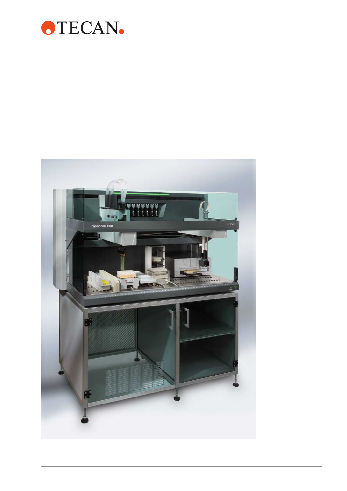
Service Manual
Freedom EVO
®
Freedom EVO Clinical
®
Freedom EVO Service Manual, 392887, en, V1.3

Customer Support
Tecan Schweiz AG and its representatives maintain a fully trained staff of technical specialists around the world. For any
technical question, contact your nearest Tecan representative or:
Tecan Schweiz AG
Seestrasse 103
CH-8708 Männedorf
Expertline Telephone
Telephone
Te le f ax
E-mail
Internet
Te le f ax
E-mail
+41 44 922 81 11
+41 44 922 81 12
info@tecan.com
www.tecan.com
+41 44 922 81 81
+41 44 922 84 84
expertline-eu@tecan.com
Document Status Sheet
Title: Freedom EVO Service Manual Part number: 10392887.02
ID: 392887, en, V1.3 Translated from:
Version Revision Issue Document History
1 0 2003-07-30 New edition
1 1 2004-03-31 Updated: Laser warnings; LiHa upgrade
Implemented: Freedom EVO Clinical; 2-tip LiHa; centrifuge maintenance,
repair and spare parts
Mentioned: EVOware software, I/O Option
1 2 2004-12-20 Implemented: Installation of Safire2 and GENios Pro readers
Minor improvements and correction of errors
1 3 2005-03-30 Minor corrections. Adaptation of spare parts numbers to SAP-numbers.
© 2005, Tecan Schweiz AG, Switzerland, all rights reserved
Information contained in this document is subject to change without notice.

Table of Contents
1 About This Manual
1.1 Reference Documents . . . . . . . . . . . . . . . . . . . . . . . . . . . . . . . . . . . . . . . . 1-2
1.2 Trademarks . . . . . . . . . . . . . . . . . . . . . . . . . . . . . . . . . . . . . . . . . . . . . . . . 1-3
1.3 Abbreviations . . . . . . . . . . . . . . . . . . . . . . . . . . . . . . . . . . . . . . . . . . . . . . . 1-3
2Safety
2.1 User Qualification. . . . . . . . . . . . . . . . . . . . . . . . . . . . . . . . . . . . . . . . . . . . 2-1
2.2 Notices and Symbols . . . . . . . . . . . . . . . . . . . . . . . . . . . . . . . . . . . . . . . . . 2-2
2.2.1 Warning Notices Used in This Manual. . . . . . . . . . . . . . . . . . . . . . . . . 2-2
2.2.2 Warning Notices Attached to the Product or Its Surroundings. . . . . . . 2-4
2.3 Product Safety . . . . . . . . . . . . . . . . . . . . . . . . . . . . . . . . . . . . . . . . . . . . . . 2-8
2.3.1 Instrument-Related Hazards and Safety Measures . . . . . . . . . . . . . . . 2-8
2.3.2 Other Hazards and Safety Measures. . . . . . . . . . . . . . . . . . . . . . . . . . 2-9
2.3.3 Safety Elements. . . . . . . . . . . . . . . . . . . . . . . . . . . . . . . . . . . . . . . . . . 2-10
2.4 Decontamination . . . . . . . . . . . . . . . . . . . . . . . . . . . . . . . . . . . . . . . . . . . . 2-13
2.5 General Safety Rules . . . . . . . . . . . . . . . . . . . . . . . . . . . . . . . . . . . . . . . . . 2-14
Table of Contents
3 Technical Data
3.1 Working Area Dimensions . . . . . . . . . . . . . . . . . . . . . . . . . . . . . . . . . . . . . 3-1
3.1.1 Ranges in X and Y-Direction . . . . . . . . . . . . . . . . . . . . . . . . . . . . . . . . 3-1
3.1.2 Ranges in Z-Direction . . . . . . . . . . . . . . . . . . . . . . . . . . . . . . . . . . . . . 3-2
3.1.3 Rotating Ranges of the RoMa . . . . . . . . . . . . . . . . . . . . . . . . . . . . . . . 3-3
3.2 Computer Requirements . . . . . . . . . . . . . . . . . . . . . . . . . . . . . . . . . . . . . . 3-4
3.3 Location of PCBs . . . . . . . . . . . . . . . . . . . . . . . . . . . . . . . . . . . . . . . . . . . . 3-5
3.3.1 Freedom EVO Base Unit . . . . . . . . . . . . . . . . . . . . . . . . . . . . . . . . . . . 3-5
3.3.2 Optional Equipment . . . . . . . . . . . . . . . . . . . . . . . . . . . . . . . . . . . . . . . 3-7
3.3.3 Options. . . . . . . . . . . . . . . . . . . . . . . . . . . . . . . . . . . . . . . . . . . . . . . . . 3-7
3.4 Configuration Data . . . . . . . . . . . . . . . . . . . . . . . . . . . . . . . . . . . . . . . . . . . 3-8
3.4.1 Arm Configurations Freedom EVO . . . . . . . . . . . . . . . . . . . . . . . . . . . 3-8
3.4.2 Optional Equipment Freedom EVO . . . . . . . . . . . . . . . . . . . . . . . . . . . 3-10
3.5 Compatibility of Options . . . . . . . . . . . . . . . . . . . . . . . . . . . . . . . . . . . . . . . 3-11
3.5.1 Available Options . . . . . . . . . . . . . . . . . . . . . . . . . . . . . . . . . . . . . . . . . 3-11
3.5.2 Available OEM Options . . . . . . . . . . . . . . . . . . . . . . . . . . . . . . . . . . . . 3-12
3.5.3 Compatibility Overview . . . . . . . . . . . . . . . . . . . . . . . . . . . . . . . . . . . . 3-13
3.5.4 Firmware Compatibility (Minimum Requirements) . . . . . . . . . . . . . . . . 3-15
Freedom EVO Service Manual, 392887, en, V1.3 i

Table of Contents
4 Installation
4.1 Site and System Preparation . . . . . . . . . . . . . . . . . . . . . . . . . . . . . . . . . . . 4-1
4.1.1 Site Requirements . . . . . . . . . . . . . . . . . . . . . . . . . . . . . . . . . . . . . . . . 4-1
4.2 Unpacking . . . . . . . . . . . . . . . . . . . . . . . . . . . . . . . . . . . . . . . . . . . . . . . . . 4-3
4.3 Transport . . . . . . . . . . . . . . . . . . . . . . . . . . . . . . . . . . . . . . . . . . . . . . . . . . 4-3
4.4 Installing and Connecting . . . . . . . . . . . . . . . . . . . . . . . . . . . . . . . . . . . . . . 4-5
4.4.1 Freedom EVO Instrument . . . . . . . . . . . . . . . . . . . . . . . . . . . . . . . . . . 4-5
4.4.2 Modules and Options . . . . . . . . . . . . . . . . . . . . . . . . . . . . . . . . . . . . . . 4-6
4.5 Checking the CAN Bus Resistance . . . . . . . . . . . . . . . . . . . . . . . . . . . . . . 4-7
4.6 Installing Options . . . . . . . . . . . . . . . . . . . . . . . . . . . . . . . . . . . . . . . . . . . . 4-9
4.6.1 Modifications on Safety Panels . . . . . . . . . . . . . . . . . . . . . . . . . . . . . . 4-9
4.6.2 Mains Outlets for Options. . . . . . . . . . . . . . . . . . . . . . . . . . . . . . . . . . . 4-10
4.6.3 Te-Link . . . . . . . . . . . . . . . . . . . . . . . . . . . . . . . . . . . . . . . . . . . . . . . . . 4-11
4.6.4 Reader . . . . . . . . . . . . . . . . . . . . . . . . . . . . . . . . . . . . . . . . . . . . . . . . . 4-17
4.6.5 Centrifuge. . . . . . . . . . . . . . . . . . . . . . . . . . . . . . . . . . . . . . . . . . . . . . . 4-18
4.7 Site Acceptance . . . . . . . . . . . . . . . . . . . . . . . . . . . . . . . . . . . . . . . . . . . . . 4-22
5 Upgrade Procedures
5.1 Modifying the Arm Configuration . . . . . . . . . . . . . . . . . . . . . . . . . . . . . . . . 5-1
5.1.1 Adding a LiHa. . . . . . . . . . . . . . . . . . . . . . . . . . . . . . . . . . . . . . . . . . . . 5-1
5.1.2 Adding a RoMa . . . . . . . . . . . . . . . . . . . . . . . . . . . . . . . . . . . . . . . . . . 5-4
5.1.3 Adding a P&P. . . . . . . . . . . . . . . . . . . . . . . . . . . . . . . . . . . . . . . . . . . . 5-5
5.1.4 Inserting an Additional X-carriage . . . . . . . . . . . . . . . . . . . . . . . . . . . . 5-7
5.2 Adding a PosID 2 . . . . . . . . . . . . . . . . . . . . . . . . . . . . . . . . . . . . . . . . . . . . 5-8
5.3 Adding a Reader . . . . . . . . . . . . . . . . . . . . . . . . . . . . . . . . . . . . . . . . . . . . 5-9
5.3.1 Introduction . . . . . . . . . . . . . . . . . . . . . . . . . . . . . . . . . . . . . . . . . . . . . 5-9
5.3.2 Installation of the Distance Brackets . . . . . . . . . . . . . . . . . . . . . . . . . . 5-11
5.3.3 Installation in Cabinet (Left Side) . . . . . . . . . . . . . . . . . . . . . . . . . . . . . 5-12
5.3.4 Installation in Cabinet (Right Side). . . . . . . . . . . . . . . . . . . . . . . . . . . . 5-15
5.3.5 Installation on Worktable Extension . . . . . . . . . . . . . . . . . . . . . . . . . . . 5-17
5.3.6 Electrical Connection . . . . . . . . . . . . . . . . . . . . . . . . . . . . . . . . . . . . . . 5-24
5.3.7 Setup and Tests . . . . . . . . . . . . . . . . . . . . . . . . . . . . . . . . . . . . . . . . . . 5-25
5.4 Lower DiTi Eject Option . . . . . . . . . . . . . . . . . . . . . . . . . . . . . . . . . . . . . . . 5-25
5.5 I/O Option . . . . . . . . . . . . . . . . . . . . . . . . . . . . . . . . . . . . . . . . . . . . . . . . . . 5-25
6 Maintenance
6.1 Tools and Consumables. . . . . . . . . . . . . . . . . . . . . . . . . . . . . . . . . . . . . . . 6-1
6.1.1 Tools . . . . . . . . . . . . . . . . . . . . . . . . . . . . . . . . . . . . . . . . . . . . . . . . . . 6-1
6.1.2 Cleaning Agents. . . . . . . . . . . . . . . . . . . . . . . . . . . . . . . . . . . . . . . . . . 6-1
6.1.3 Lubricants. . . . . . . . . . . . . . . . . . . . . . . . . . . . . . . . . . . . . . . . . . . . . . . 6-2
6.2 Maintenance Schedule. . . . . . . . . . . . . . . . . . . . . . . . . . . . . . . . . . . . . . . . 6-2
6.2.1 Maintenance Table: Basic Tasks to Be Performed . . . . . . . . . . . . . . . 6-3
6.2.2 Maintenance Table: Half-Yearly Maintenance . . . . . . . . . . . . . . . . . . . 6-3
6.2.3 Maintenance Table: Yearly Maintenance . . . . . . . . . . . . . . . . . . . . . . . 6-3
6.2.4 Maintenance Table: Special Intervals . . . . . . . . . . . . . . . . . . . . . . . . . 6-4
6.3 Maintenance Tasks . . . . . . . . . . . . . . . . . . . . . . . . . . . . . . . . . . . . . . . . . . 6-5
6.3.1 Cleaning the System . . . . . . . . . . . . . . . . . . . . . . . . . . . . . . . . . . . . . . 6-5
6.3.2 Cleaning Parts of the Arms . . . . . . . . . . . . . . . . . . . . . . . . . . . . . . . . . 6-5
6.3.3 Centrifuge. . . . . . . . . . . . . . . . . . . . . . . . . . . . . . . . . . . . . . . . . . . . . . . 6-6
ii Freedom EVO Service Manual, 392887, en, V1.3

Table of Contents
7 Troubleshooting
7.1 Troubleshooting Table . . . . . . . . . . . . . . . . . . . . . . . . . . . . . . . . . . . . . . . . 7-1
7.2 Troubleshooting Instructions . . . . . . . . . . . . . . . . . . . . . . . . . . . . . . . . . . . 7-10
7.2.1 Status LEDs on PCBs . . . . . . . . . . . . . . . . . . . . . . . . . . . . . . . . . . . . . 7-10
7.2.2 Power LEDs on Optibo DCU . . . . . . . . . . . . . . . . . . . . . . . . . . . . . . . . 7-11
Freedom EVO Service Manual, 392887, en, V1.3 iii

Table of Contents
8 Repair
8.1 General Notes on Repair . . . . . . . . . . . . . . . . . . . . . . . . . . . . . . . . . . . . . . 8-1
8.1.1 Electrical Safety . . . . . . . . . . . . . . . . . . . . . . . . . . . . . . . . . . . . . . . . . . 8-1
8.1.2 Marking Connectors . . . . . . . . . . . . . . . . . . . . . . . . . . . . . . . . . . . . . . . 8-1
8.2 Safety Panels / Covers. . . . . . . . . . . . . . . . . . . . . . . . . . . . . . . . . . . . . . . . 8-2
8.2.1 Access to Components . . . . . . . . . . . . . . . . . . . . . . . . . . . . . . . . . . . . 8-2
8.2.2 Gas Spring . . . . . . . . . . . . . . . . . . . . . . . . . . . . . . . . . . . . . . . . . . . . . . 8-3
8.2.3 Door Locks . . . . . . . . . . . . . . . . . . . . . . . . . . . . . . . . . . . . . . . . . . . . . . 8-4
8.3 Worktable . . . . . . . . . . . . . . . . . . . . . . . . . . . . . . . . . . . . . . . . . . . . . . . . . . 8-5
8.3.1 Spare Parts Worktable . . . . . . . . . . . . . . . . . . . . . . . . . . . . . . . . . . . . . 8-5
8.4 System Electronics. . . . . . . . . . . . . . . . . . . . . . . . . . . . . . . . . . . . . . . . . . . 8-6
8.4.1 Spare Parts Electronics . . . . . . . . . . . . . . . . . . . . . . . . . . . . . . . . . . . . 8-6
8.4.2 Te-CU Board . . . . . . . . . . . . . . . . . . . . . . . . . . . . . . . . . . . . . . . . . . . . 8-7
8.4.3 Optibo DCU . . . . . . . . . . . . . . . . . . . . . . . . . . . . . . . . . . . . . . . . . . . . . 8-7
8.4.4 DCU 2 Board . . . . . . . . . . . . . . . . . . . . . . . . . . . . . . . . . . . . . . . . . . . . 8-8
8.4.5 Gate Board. . . . . . . . . . . . . . . . . . . . . . . . . . . . . . . . . . . . . . . . . . . . . . 8-9
8.4.6 SMIO/SAFY Board . . . . . . . . . . . . . . . . . . . . . . . . . . . . . . . . . . . . . . . . 8-10
8.4.7 ON/OFF/Pause/Resume Switch . . . . . . . . . . . . . . . . . . . . . . . . . . . . . 8-10
8.4.8 Status Lamp . . . . . . . . . . . . . . . . . . . . . . . . . . . . . . . . . . . . . . . . . . . . . 8-12
8.5 Power Supply Module . . . . . . . . . . . . . . . . . . . . . . . . . . . . . . . . . . . . . . . . 8-13
8.5.1 Spare Parts Power Supply Module . . . . . . . . . . . . . . . . . . . . . . . . . . . 8-14
8.5.2 Replacing Power Supply Module . . . . . . . . . . . . . . . . . . . . . . . . . . . . . 8-15
8.6 X-Drive Assembly and X-Carriage . . . . . . . . . . . . . . . . . . . . . . . . . . . . . . . 8-17
8.6.1 Spare Parts X-Drive Assembly. . . . . . . . . . . . . . . . . . . . . . . . . . . . . . . 8-17
8.6.2 X-Drive Assembly. . . . . . . . . . . . . . . . . . . . . . . . . . . . . . . . . . . . . . . . . 8-17
8.6.3 X-Carriage . . . . . . . . . . . . . . . . . . . . . . . . . . . . . . . . . . . . . . . . . . . . . . 8-19
8.7 Liquid Handling Arm (LiHa) . . . . . . . . . . . . . . . . . . . . . . . . . . . . . . . . . . . . 8-22
8.7.1 Overview . . . . . . . . . . . . . . . . . . . . . . . . . . . . . . . . . . . . . . . . . . . . . . . 8-22
8.7.2 Spare Parts LiHa . . . . . . . . . . . . . . . . . . . . . . . . . . . . . . . . . . . . . . . . . 8-23
8.7.3 Complete LiHa Arm . . . . . . . . . . . . . . . . . . . . . . . . . . . . . . . . . . . . . . . 8-23
8.7.4 Tip Adapter. . . . . . . . . . . . . . . . . . . . . . . . . . . . . . . . . . . . . . . . . . . . . . 8-27
8.7.5 Electronic Boards and Cables . . . . . . . . . . . . . . . . . . . . . . . . . . . . . . . 8-29
8.7.6 Y-Belt . . . . . . . . . . . . . . . . . . . . . . . . . . . . . . . . . . . . . . . . . . . . . . . . . . 8-38
8.8 Y-Motors. . . . . . . . . . . . . . . . . . . . . . . . . . . . . . . . . . . . . . . . . . . . . . . . . . . 8-41
8.8.1 Z-Motors. . . . . . . . . . . . . . . . . . . . . . . . . . . . . . . . . . . . . . . . . . . . . . . . 8-42
8.8.2 Square Shaft/Pinion Gear . . . . . . . . . . . . . . . . . . . . . . . . . . . . . . . . . . 8-44
8.8.3 Lower DiTi Eject Option . . . . . . . . . . . . . . . . . . . . . . . . . . . . . . . . . . . . 8-47
8.9 Robotic Manipulator Arm (RoMa Standard, Long) . . . . . . . . . . . . . . . . . . . 8-53
8.9.1 Overview . . . . . . . . . . . . . . . . . . . . . . . . . . . . . . . . . . . . . . . . . . . . . . . 8-53
8.9.2 Spare Parts RoMa . . . . . . . . . . . . . . . . . . . . . . . . . . . . . . . . . . . . . . . . 8-55
8.9.3 Basic Considerations . . . . . . . . . . . . . . . . . . . . . . . . . . . . . . . . . . . . . . 8-57
8.9.4 Complete RoMa Arm . . . . . . . . . . . . . . . . . . . . . . . . . . . . . . . . . . . . . . 8-57
8.9.5 Mechanical Adjustment After Reinstallation. . . . . . . . . . . . . . . . . . . . . 8-60
8.9.6 Gripper Fingers . . . . . . . . . . . . . . . . . . . . . . . . . . . . . . . . . . . . . . . . . . 8-63
8.9.7 Gripper Module Head . . . . . . . . . . . . . . . . . . . . . . . . . . . . . . . . . . . . . . 8-64
8.9.8 R-motor . . . . . . . . . . . . . . . . . . . . . . . . . . . . . . . . . . . . . . . . . . . . . . . . 8-67
8.9.9 Y-flex cable . . . . . . . . . . . . . . . . . . . . . . . . . . . . . . . . . . . . . . . . . . . . . 8-68
8.9.10 Gripper/Rotator Flex Cables . . . . . . . . . . . . . . . . . . . . . . . . . . . . . . . . 8-69
8.9.11 Y/R- and Z/G-DC Servo (II) Boards . . . . . . . . . . . . . . . . . . . . . . . . . . . 8-70
8.9.12 RoMa 2 Backplane. . . . . . . . . . . . . . . . . . . . . . . . . . . . . . . . . . . . . . . . 8-72
8.9.13 Y-Belt . . . . . . . . . . . . . . . . . . . . . . . . . . . . . . . . . . . . . . . . . . . . . . . . . . 8-73
8.9.14 Y-motor . . . . . . . . . . . . . . . . . . . . . . . . . . . . . . . . . . . . . . . . . . . . . . . . 8-75
8.9.15 Z-motor. . . . . . . . . . . . . . . . . . . . . . . . . . . . . . . . . . . . . . . . . . . . . . . . . 8-76
iv Freedom EVO Service Manual, 392887, en, V1.3

Table of Contents
8.9.16 Z-Brake . . . . . . . . . . . . . . . . . . . . . . . . . . . . . . . . . . . . . . . . . . . . . . . . 8-77
8.9.17 RoMa Freedom Backplane . . . . . . . . . . . . . . . . . . . . . . . . . . . . . . . . . 8-79
8.9.18 Device CU . . . . . . . . . . . . . . . . . . . . . . . . . . . . . . . . . . . . . . . . . . . . . . 8-81
8.9.19 X-DC Servo Power Board . . . . . . . . . . . . . . . . . . . . . . . . . . . . . . . . . . 8-82
8.9.20 Checking RoMa Operating Readiness. . . . . . . . . . . . . . . . . . . . . . . . . 8-84
8.10 Pick and Place Arm (P&P) . . . . . . . . . . . . . . . . . . . . . . . . . . . . . . . . . . . . . 8-85
8.10.1 General Information . . . . . . . . . . . . . . . . . . . . . . . . . . . . . . . . . . . . . . . 8-85
8.10.2 Spare Parts P&P . . . . . . . . . . . . . . . . . . . . . . . . . . . . . . . . . . . . . . . . . 8-85
8.10.3 Complete P&P Arm . . . . . . . . . . . . . . . . . . . . . . . . . . . . . . . . . . . . . . . 8-85
8.10.4 Electronic Boards. . . . . . . . . . . . . . . . . . . . . . . . . . . . . . . . . . . . . . . . . 8-87
8.10.5 Belts . . . . . . . . . . . . . . . . . . . . . . . . . . . . . . . . . . . . . . . . . . . . . . . . . . . 8-90
8.10.6 Motors . . . . . . . . . . . . . . . . . . . . . . . . . . . . . . . . . . . . . . . . . . . . . . . . . 8-94
8.10.7 Gripper Head and Fingers . . . . . . . . . . . . . . . . . . . . . . . . . . . . . . . . . . 8-97
8.10.8 Solenoid Z-Brake . . . . . . . . . . . . . . . . . . . . . . . . . . . . . . . . . . . . . . . . . 8-100
8.11 X-Flex Cables. . . . . . . . . . . . . . . . . . . . . . . . . . . . . . . . . . . . . . . . . . . . . . . 8-102
8.11.1 Installing X-Flex Cables . . . . . . . . . . . . . . . . . . . . . . . . . . . . . . . . . . . . 8-102
8.11.2 X-Flex Cable Bend Drawings. . . . . . . . . . . . . . . . . . . . . . . . . . . . . . . . 8-104
8.12 PosID 2 . . . . . . . . . . . . . . . . . . . . . . . . . . . . . . . . . . . . . . . . . . . . . . . . . . . 8-105
8.12.1 Spare Parts PosID 2 . . . . . . . . . . . . . . . . . . . . . . . . . . . . . . . . . . . . . . 8-105
8.12.2 Complete PosID 2 Assembly . . . . . . . . . . . . . . . . . . . . . . . . . . . . . . . . 8-106
8.12.3 X-Drive Assembly . . . . . . . . . . . . . . . . . . . . . . . . . . . . . . . . . . . . . . . . 8-109
8.12.4 Electronic Boards. . . . . . . . . . . . . . . . . . . . . . . . . . . . . . . . . . . . . . . . . 8-113
8.12.5 Scanner Assembly . . . . . . . . . . . . . . . . . . . . . . . . . . . . . . . . . . . . . . . . 8-117
8.12.6 Y-Drive Assembly . . . . . . . . . . . . . . . . . . . . . . . . . . . . . . . . . . . . . . . . 8-120
8.12.7 No Tube Sensor. . . . . . . . . . . . . . . . . . . . . . . . . . . . . . . . . . . . . . . . . . 8-123
8.13 Te-Link . . . . . . . . . . . . . . . . . . . . . . . . . . . . . . . . . . . . . . . . . . . . . . . . . . . . 8-125
8.13.1 Spare Parts . . . . . . . . . . . . . . . . . . . . . . . . . . . . . . . . . . . . . . . . . . . . . 8-125
8.13.2 Complete Te-Link. . . . . . . . . . . . . . . . . . . . . . . . . . . . . . . . . . . . . . . . . 8-125
8.13.3 Making the Parts Accessible . . . . . . . . . . . . . . . . . . . . . . . . . . . . . . . . 8-125
8.13.4 Toothed Belt. . . . . . . . . . . . . . . . . . . . . . . . . . . . . . . . . . . . . . . . . . . . . 8-127
8.13.5 Motor Assembly . . . . . . . . . . . . . . . . . . . . . . . . . . . . . . . . . . . . . . . . . . 8-129
8.13.6 DC Servo II Board . . . . . . . . . . . . . . . . . . . . . . . . . . . . . . . . . . . . . . . . 8-131
8.13.7 Device CU Board . . . . . . . . . . . . . . . . . . . . . . . . . . . . . . . . . . . . . . . . . 8-132
8.13.8 Te-Stack Backplane. . . . . . . . . . . . . . . . . . . . . . . . . . . . . . . . . . . . . . . 8-133
8.14 Centrifuge. . . . . . . . . . . . . . . . . . . . . . . . . . . . . . . . . . . . . . . . . . . . . . . . . . 8-134
8.14.1 Spare Parts . . . . . . . . . . . . . . . . . . . . . . . . . . . . . . . . . . . . . . . . . . . . . 8-134
8.14.2 Removal of the Centrifuge . . . . . . . . . . . . . . . . . . . . . . . . . . . . . . . . . . 8-134
8.14.3 Removal of Upper Front Panel . . . . . . . . . . . . . . . . . . . . . . . . . . . . . . 8-134
8.14.4 Temperature Sensors . . . . . . . . . . . . . . . . . . . . . . . . . . . . . . . . . . . . . 8-135
8.14.5 Fuses . . . . . . . . . . . . . . . . . . . . . . . . . . . . . . . . . . . . . . . . . . . . . . . . . . 8-138
8.14.6 Imbalance Switch Adjustment . . . . . . . . . . . . . . . . . . . . . . . . . . . . . . . 8-140
8.15 Liquid System. . . . . . . . . . . . . . . . . . . . . . . . . . . . . . . . . . . . . . . . . . . . . . . 8-141
8.15.1 Overview . . . . . . . . . . . . . . . . . . . . . . . . . . . . . . . . . . . . . . . . . . . . . . . 8-141
8.15.2 Tubing System . . . . . . . . . . . . . . . . . . . . . . . . . . . . . . . . . . . . . . . . . . . 8-142
8.15.3 Low Volume Option . . . . . . . . . . . . . . . . . . . . . . . . . . . . . . . . . . . . . . . 8-144
8.15.4 Monitored Pump Option/Fast Wash Option . . . . . . . . . . . . . . . . . . . . . 8-147
8.15.5 Diluters. . . . . . . . . . . . . . . . . . . . . . . . . . . . . . . . . . . . . . . . . . . . . . . . . 8-154
8.16 Settings . . . . . . . . . . . . . . . . . . . . . . . . . . . . . . . . . . . . . . . . . . . . . . . . . . . 8-160
8.16.1 Address Settings Overview . . . . . . . . . . . . . . . . . . . . . . . . . . . . . . . . . 8-160
8.16.2 Volume of the Acoustic Alarm Device . . . . . . . . . . . . . . . . . . . . . . . . . 8-162
Freedom EVO Service Manual, 392887, en, V1.3 v

Table of Contents
9 Shutdown, Storage and Shipping
9.1 Shutdown . . . . . . . . . . . . . . . . . . . . . . . . . . . . . . . . . . . . . . . . . . . . . . . . . . 9-1
9.2 Storage. . . . . . . . . . . . . . . . . . . . . . . . . . . . . . . . . . . . . . . . . . . . . . . . . . . . 9-1
9.2.1 Packaging . . . . . . . . . . . . . . . . . . . . . . . . . . . . . . . . . . . . . . . . . . . . . . 9-2
9.3 Shipping . . . . . . . . . . . . . . . . . . . . . . . . . . . . . . . . . . . . . . . . . . . . . . . . . . . 9-9
10 Spare Parts and Accessories
10.1 Base Unit . . . . . . . . . . . . . . . . . . . . . . . . . . . . . . . . . . . . . . . . . . . . . . . . . . 10-1
10.2 Safety Panels . . . . . . . . . . . . . . . . . . . . . . . . . . . . . . . . . . . . . . . . . . . . . . . 10-2
10.3 System Electronics. . . . . . . . . . . . . . . . . . . . . . . . . . . . . . . . . . . . . . . . . . . 10-2
10.4 Liquid Handling Arm (LiHa) . . . . . . . . . . . . . . . . . . . . . . . . . . . . . . . . . . . . 10-3
10.5 Robotic Manipulator Arm (RoMa). . . . . . . . . . . . . . . . . . . . . . . . . . . . . . . . 10-4
10.6 Pick and Place (P&P) . . . . . . . . . . . . . . . . . . . . . . . . . . . . . . . . . . . . . . . . . 10-6
10.7 PosID . . . . . . . . . . . . . . . . . . . . . . . . . . . . . . . . . . . . . . . . . . . . . . . . . . . . . 10-7
10.8 Te-Link . . . . . . . . . . . . . . . . . . . . . . . . . . . . . . . . . . . . . . . . . . . . . . . . . . . . 10-8
10.9 Liquid System. . . . . . . . . . . . . . . . . . . . . . . . . . . . . . . . . . . . . . . . . . . . . . . 10-8
10.9.1 Standard Tubing. . . . . . . . . . . . . . . . . . . . . . . . . . . . . . . . . . . . . . . . . . 10-8
10.9.2 High Resistant Tubing Type A . . . . . . . . . . . . . . . . . . . . . . . . . . . . . . . 10-9
10.9.3 High Resistant Tubing Type B . . . . . . . . . . . . . . . . . . . . . . . . . . . . . . . 10-9
10.9.4 Low Volume Option . . . . . . . . . . . . . . . . . . . . . . . . . . . . . . . . . . . . . . . 10-10
10.9.5 Monitored Pump Option/Fast Wash Option . . . . . . . . . . . . . . . . . . . . . 10-10
10.9.6 Diluters . . . . . . . . . . . . . . . . . . . . . . . . . . . . . . . . . . . . . . . . . . . . . . . . . 10-11
10.10 Centrifuge. . . . . . . . . . . . . . . . . . . . . . . . . . . . . . . . . . . . . . . . . . . . . . . . . . 10-12
10.11 Reader . . . . . . . . . . . . . . . . . . . . . . . . . . . . . . . . . . . . . . . . . . . . . . . . . . . . 10-13
10.12 Accessories and Options . . . . . . . . . . . . . . . . . . . . . . . . . . . . . . . . . . . . . . 10-14
10.13 Tools. . . . . . . . . . . . . . . . . . . . . . . . . . . . . . . . . . . . . . . . . . . . . . . . . . . . . . 10-14
vi Freedom EVO Service Manual, 392887, en, V1.3

Table of Contents
11 Diagrams
11.1 Overview . . . . . . . . . . . . . . . . . . . . . . . . . . . . . . . . . . . . . . . . . . . . . . . . . . 11-1
11.2 Diagram Pages . . . . . . . . . . . . . . . . . . . . . . . . . . . . . . . . . . . . . . . . . . . . . 11-2
11.2.1 Communication Overview . . . . . . . . . . . . . . . . . . . . . . . . . . . . . . . . . . 11-3
11.2.2 Arm Configurations . . . . . . . . . . . . . . . . . . . . . . . . . . . . . . . . . . . . . . . 11-4
11.2.3 Wiring Diagram Freedom EVO . . . . . . . . . . . . . . . . . . . . . . . . . . . . . . 11-5
11.2.4 Wiring Diagram Diluters . . . . . . . . . . . . . . . . . . . . . . . . . . . . . . . . . . . . 11-6
11.2.5 Wiring Diagram LiHa 2-Channel . . . . . . . . . . . . . . . . . . . . . . . . . . . . . 11-7
11.2.6 Wiring Diagram LiHa 4-Channel . . . . . . . . . . . . . . . . . . . . . . . . . . . . . 11-8
11.2.7 Wiring Diagram LiHa 8-Channel . . . . . . . . . . . . . . . . . . . . . . . . . . . . . 11-9
11.2.8 Wiring Diagram MPO . . . . . . . . . . . . . . . . . . . . . . . . . . . . . . . . . . . . . . 11-10
11.2.9 Wiring Diagram RoMa (DC Servo). . . . . . . . . . . . . . . . . . . . . . . . . . . . 11-11
11.2.10 Wiring Diagram RoMa (DC Servo II) . . . . . . . . . . . . . . . . . . . . . . . . . . 11-12
11.2.11 Wiring Diagram P&P . . . . . . . . . . . . . . . . . . . . . . . . . . . . . . . . . . . . . . 11-13
11.2.12 Wiring Diagram PosID 2 . . . . . . . . . . . . . . . . . . . . . . . . . . . . . . . . . . . 11-14
11.2.13 Wiring Diagram Access Functions . . . . . . . . . . . . . . . . . . . . . . . . . . . . 11-15
11.2.14 Wiring Diagram Te-Link . . . . . . . . . . . . . . . . . . . . . . . . . . . . . . . . . . . . 11-16
11.2.15 CU PosID 2 (PCB) . . . . . . . . . . . . . . . . . . . . . . . . . . . . . . . . . . . . . . . . 11-17
11.2.16 P&P Backplane (PCB) . . . . . . . . . . . . . . . . . . . . . . . . . . . . . . . . . . . . . 11-18
11.2.17 Gate Board (PCB) . . . . . . . . . . . . . . . . . . . . . . . . . . . . . . . . . . . . . . . . 11-19
11.2.18 SMIO/SAFY Board (PCB) . . . . . . . . . . . . . . . . . . . . . . . . . . . . . . . . . . 11-20
11.2.19 RoMa Freedom Backplane (PCB) . . . . . . . . . . . . . . . . . . . . . . . . . . . . 11-21
11.2.20 RoMa 2 Backplane (PCB) . . . . . . . . . . . . . . . . . . . . . . . . . . . . . . . . . . 11-22
11.2.21 DC Servo [II], [Power] (PCB) . . . . . . . . . . . . . . . . . . . . . . . . . . . . . . . . 11-23
11.2.22 Te-CU (PCB) . . . . . . . . . . . . . . . . . . . . . . . . . . . . . . . . . . . . . . . . . . . . 11-24
11.2.23 Optibo DCU (PCB). . . . . . . . . . . . . . . . . . . . . . . . . . . . . . . . . . . . . . . . 11-25
11.2.24 LiHa 1536 Backplane (PCB) . . . . . . . . . . . . . . . . . . . . . . . . . . . . . . . . 11-26
11.2.25 ILID-Freedom Protected (PCB) . . . . . . . . . . . . . . . . . . . . . . . . . . . . . . 11-27
11.2.26 VCC Dilback (PCB) . . . . . . . . . . . . . . . . . . . . . . . . . . . . . . . . . . . . . . . 11-28
11.2.27 MPO Board (PCB) . . . . . . . . . . . . . . . . . . . . . . . . . . . . . . . . . . . . . . . . 11-29
11.2.28 Te-Stack Backplane (PCB) . . . . . . . . . . . . . . . . . . . . . . . . . . . . . . . . . 11-30
12 Index
Freedom EVO Service Manual, 392887, en, V1.3 vii

Table of Contents
viii Freedom EVO Service Manual, 392887, en, V1.3

1 About This Manual
1 - About This Manual
Purpose of This
Chapter
This chapter points out the purpose of the manual, specifies the product the
manual deals with and who the manual is intended for. Furthermore, it explains
the symbols, conventions and abbreviations used and offers other general
Purpose of This
Manual
information.
This Service Manual describes the installation and the setup of the Freedom EVO.
Furthermore, it offers help for troubleshooting and provides all necessary
information on maintenance and repair.
Target Group This manual is intended for qualified field service engineers only. These personnel
have received appropriate service training and are authorized to carry out the
maintenance and service work described in this Service Manual.
Scope This manual is applicable for the
Freedom EVO 100; Part No. 641241; from serial No. 0201.
Freedom EVO 150; Part No. 641441; from serial No. 0201.
Freedom EVO 200; Part No. 641541; from serial No. 0201.
Freedom EVO Clinical 100; Part No. 641242; from serial No. 0201.
Freedom EVO Clinical 150; Part No. 641442; from serial No. 0201.
Freedom EVO Clinical 200; Part No. 641542; from serial No. 0201.
Symbols and
Conventions
Cross-references appear as follows: e.g. “Refer to section 1.1.1, 1-1”
– 1.1.1 refers to the corresponding section number
– The symbol
denotes “page number”
– 1-1 refers to the page number, whereas the first number stands for the
chapter number (chapter 1 - page 1)
Note: The symbols pertaining to safety (WARNINGS and ATTENTIONS) are
explained in Chapter 2 “Safety”,
2-1.
For Your Safety Before performing any work on or with the Freedom EVO, first read the
Service Manual carefully, in particular chapter 2 “Safety”.
Freedom EVO Service Manual, 392887, en, V1.3 1 - 1

1 - About This Manual
Reference Documents
1.1 Reference Documents
This section provides a list of documents which are needed or may be useful in
connection with the Freedom EVO.
They either concern the instrument or options of the Freedom EVO.
What Does the
Doc. ID Tell
You?
Instrument
Documents
Application
Software
Setup & Service
Software
Freedom EVO
Options
Centrifuge
(Option)
The Doc. IDs listed below are root numbers. Therefore, they do not contain
information about the language, document version or the medium (data storage
medium, hardcopy, downloadable file, etc.) the document is published with.
Check the scope of the corresponding document to make sure that you are in
possession of the correct version.
Note: The Doc. ID does not represent ordering information. For orders refer to the
number on the binder, CD casing, etc.
Freedom EVO Operating Manual (Doc. ID 392 886)
Freedom EVO Clinical Operating Manual (Doc. ID 393 062)
Freedom EVO Maintenance and Service Logbook (Doc. ID 392 815)
Gemini Software Manual (Doc. ID 391 201)
FACTS Software Manual (Doc. ID 391 252)
Logic Application Software Manual (Doc. ID 391 117)
Instrument Software Manual (Doc. ID 392 888)
According to used options.
Rotanta 46 RSC ROBOTIC Operating Instruction (Hettich, AB090GB)
Rotanta 46 RSC ROBOTIC Repair instructions (Hettich, AR090GB)
Reader (Option) Safire
Safire
2
Operating Manual (I 112 942)
2
Technical Manual (T 112 942)
GENios Pro Operating Manual (I 112 935)
GENios Pro Technical Manual (T 112 935)
Ultra Operating Manual (I 112 910)
Ultra Technical Manual (T 112 910)
Supplementary
Information
Order Configuration/Packing List for Freedom EVO (Doc. ID 392 885)
Order Configuration/Packing List for Freedom EVO Clinical (Doc. ID 393 070)
Order Configuration/Packing List for EVO Upgrades (Doc. ID 393 178)
Forms Instrument Decontamination Form (Doc. ID 390 901)
Installation Qualification (Doc ID 392 816)
Operation Qualification (Doc ID 392 817)
Freedom EVO Preventive Maintenance Checklist (Doc ID 392 819)
Freedom EVO Service Checklist (Doc ID 392 820)
1 - 2 Freedom EVO Service Manual, 392887, en, V1.3

1 - About This Manual
1.2 Trademarks
The following product names and any registered and unregistered trademarks
mentioned in this manual are used for identification purposes only and remain the
exclusive property of their respective owners:
Freedom EVOware®, Freedom EVO® and Genesis Freedom
are registered trademarks of Tecan Group Ltd in major countries .
Te fl on
®
is a registered trademarks of E.I. du Pont de Nemours and Company.
Tygon
®
is a registered trademarks of Norton Performance Plastics Corporation (a
Saint-Gobain Company).
®
Trademarks
1.3 Abbreviations
The following abbreviations are used in this manual:
CAN Controller Area Network
DCU Device Control Unit
DMSO Dimethyl Sulfoxide
FaWa Fast Wash Pump
FEP Fluorinated Ethylene Propylene
FSE Field Service Engineer
FWO Fast Wash Option
ILID Integrated Liquid Detection
LH Liquid Handling
LICOS Liquid Container Supervisor
LiHa Liquid Handling arm
MP Microplate
MPO Monitored Pump Option
NPS Nanopipetting System
PCB Printed Circuit Board
PosID Positive Identification Option (barcode reader)
PP Polypropylene
PVDF Polyvinylidene Fluoride
RoMa Robotic Manipulator arm
Te- PS Tecan Positioning System
Freedom EVO Service Manual, 392887, en, V1.3 1 - 3

1 - About This Manual
Abbreviations
1 - 4 Freedom EVO Service Manual, 392887, en, V1.3

2 Safety
User Qualification
2 - Safety
Purpose of This
Chapter
Significance of
These Safety
Instructions
FSE
Authorization
This chapter contains specific rules of behavior and warnings from hazards
related to installation, setup, troubleshooting, maintenance and repair of the
Freedom EVO.
The safety of users and personnel can only be ensured if these safety instructions
and the safety-related warnings in the individual chapters are strictly observed
and followed.
Therefore, the Service Manual must always be available to all persons performing
the tasks described herein.
In addition to the safety instructions given in this Service Manual, the safety
instructions pointed out in the Operating Manual of the Freedom EVO apply as
well.
2.1 User Qualification
The field service engineers (FSE) are specially trained personnel. Exclusively
FSEs are entitled to perform the maintenance and service work described in this
Service Manual.
The manufacturer Tecan authorizes the FSEs if they fulfill the following particular
qualifications:
They must have received appropriate service and operator training from
Te ca n .
They must be familiar with the good laboratory practice guidelines.
They must have read and understood the instructions in this Service Manual.
Freedom EVO Service Manual, 392887, en, V1.3 2 - 1
2 - Safety
Notices and Symbols
2.2 Notices and Symbols
2.2.1 Warning Notices Used in This Manual
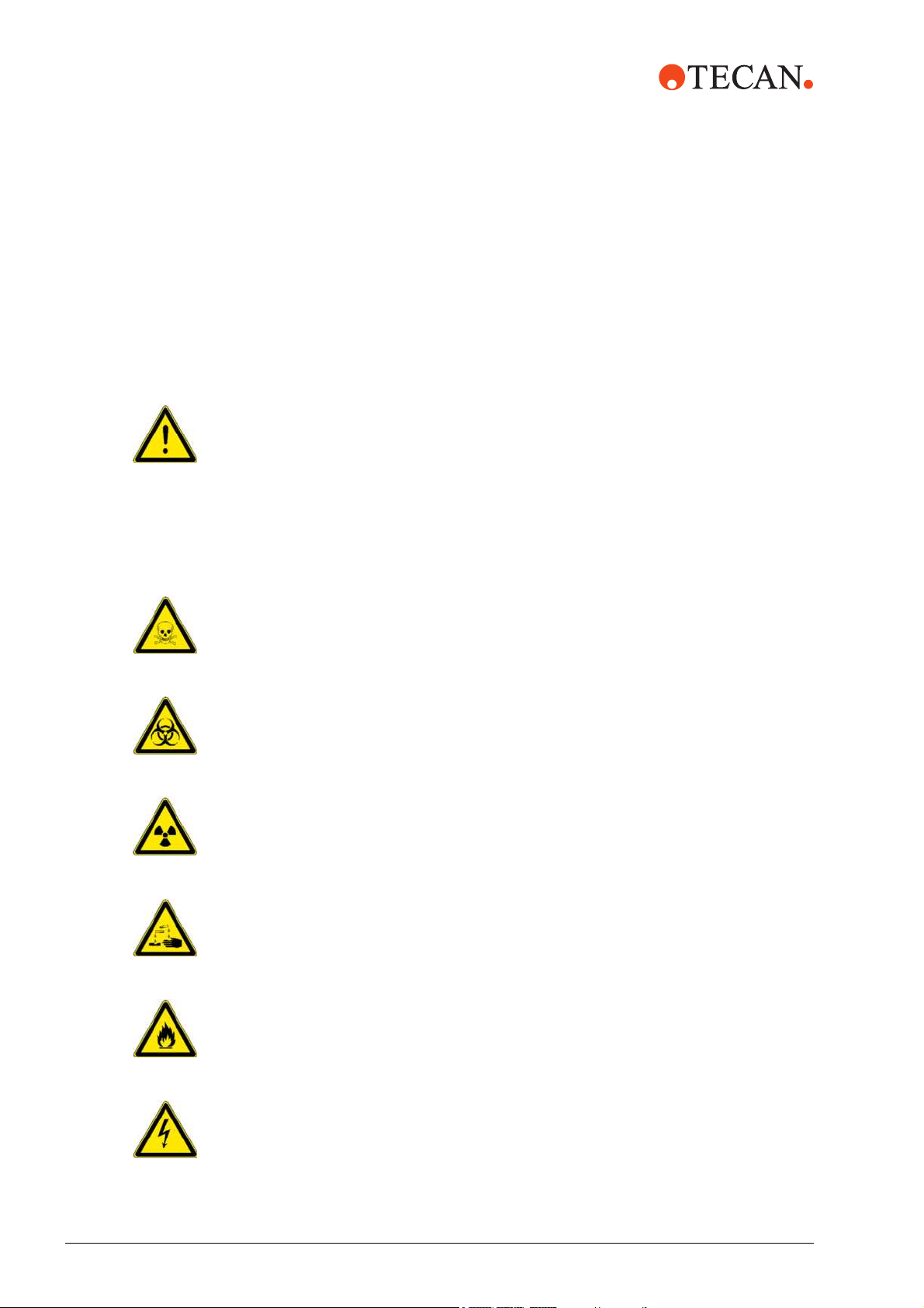
The symbols used for safety-related notices have the following significance:
WARNING
Symbols
WARNING notices appear as follows:
WARNING
Generally, the triangular warning symbol indicates the possibility of personal injury
or even loss of life if the instructions are not followed.
Whenever possible, the symbol indicates the hazard a person is exposed to more
specifically. The symbols used in this Service Manual have the following
significance:
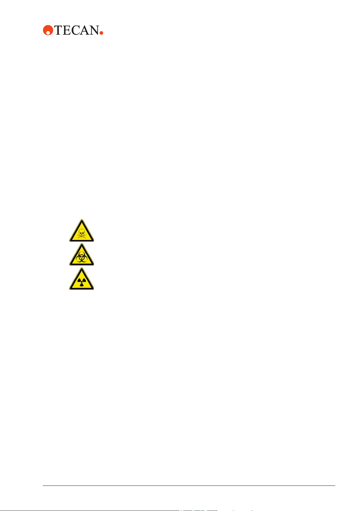
WARNING
Toxic substances
WARNING
Biological hazard
WARNING
Radioactive radiation
WARNING
Caustic substances
WARNING
Fire hazard
WARNING
Electrical danger
2 - 2 Freedom EVO Service Manual, 392887, en, V1.3
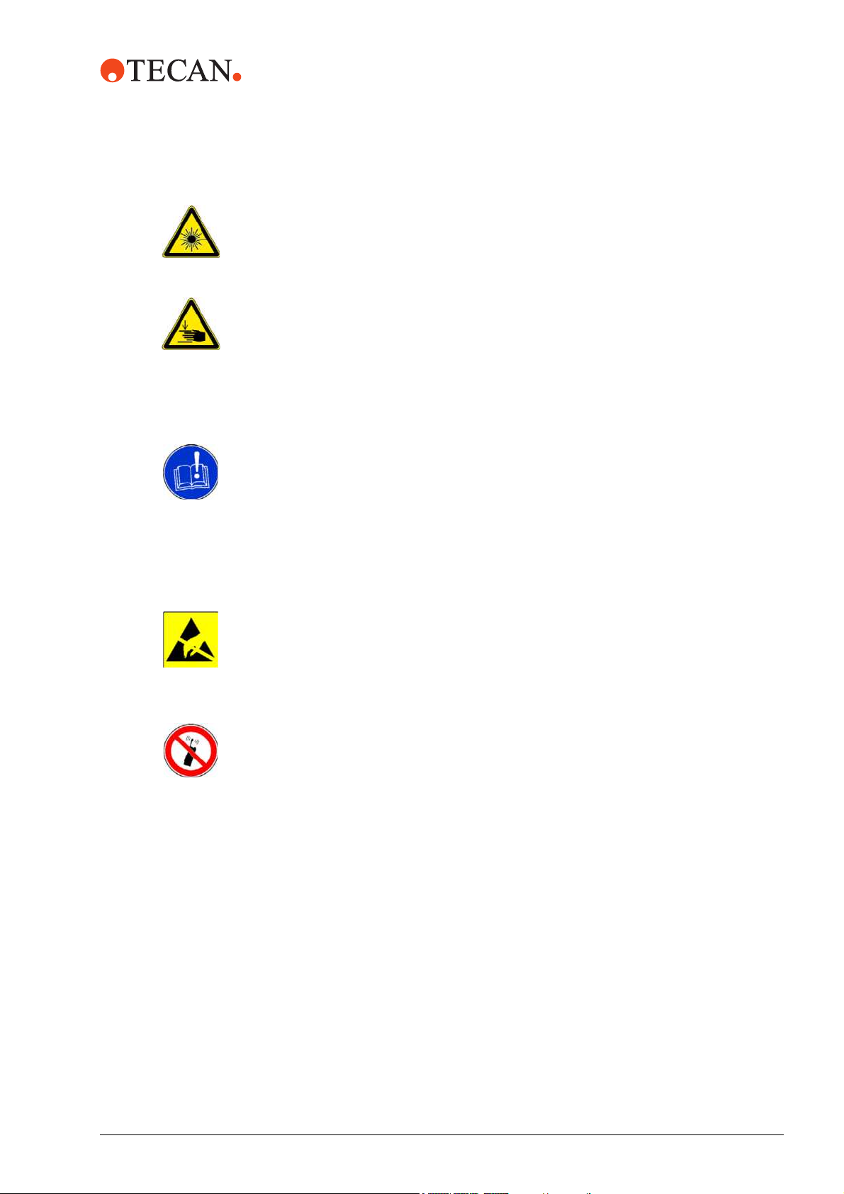
WARNING
Laser hazard
WARNING
Pinch point, mechanical hazards
Notices and Symbols
2 - Safety
ATTE NTION
Symbols
ATTENTION notes appear as follows:
ATTENTION
With the general “Read This!” symbol, ATTENTIONs indicate the possibility of
equipment damage, malfunctions or incorrect process results, if instructions are
not followed.
Other symbols indicate the significance of the ATTENTION more specifically:
ATTENTION
Damage to electronics by electrostatic discharge.
Always follow ESD safety practices.
ATTENTION
Disturbance of functions by electromagnetic RF waves.
Do not use a cellular phone.
Freedom EVO Service Manual, 392887, en, V1.3 2 - 3
2 - Safety
Notices and Symbols
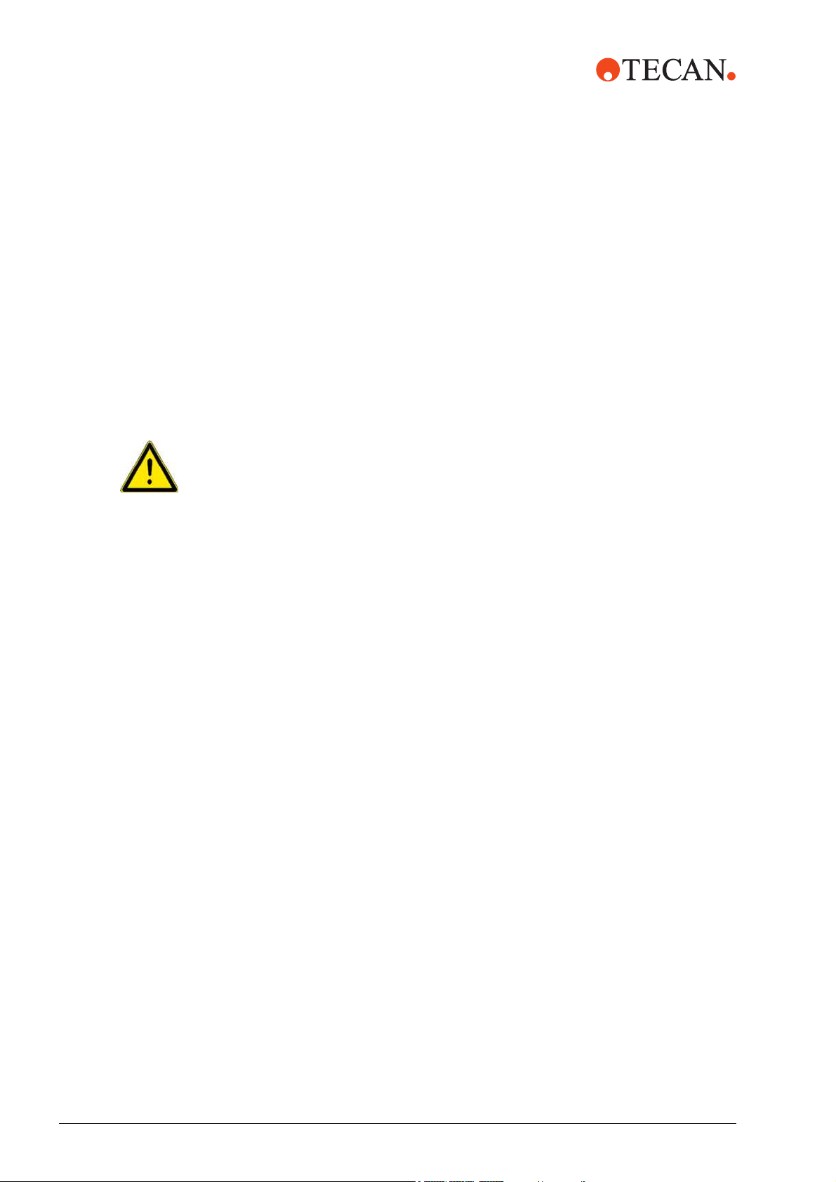
2.2.2 Warning Notices Attached to the Product or Its Surroundings
Where are
Safety Notices
Attached?
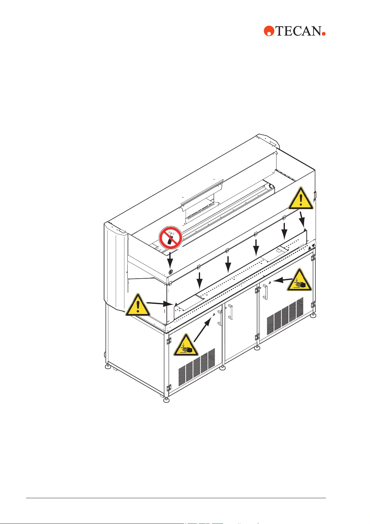
Freedom EVO Instrument
The figure shows the safety notices that are attached to the Freedom EVO
instrument. It also shows their locations:
Fig. 2-1 Safety notices attached to the product
The following table explains the significance of the notices:
2 - 4 Freedom EVO Service Manual, 392887, en, V1.3
Tab. 2-1 Significance of the safety notices
Symbol Significance Location
Notices and Symbols
2 - Safety
Safety Notices
on the PosID
Warning of hazards if you reach
beyond the yellow line (see short
arrows)
Warning of hazarzs if you reach
into the cabinet if, for instance, a
reader or centrifuge is installed.
Do not use a cellular phone See Fig. 2-1, 2-4
See Fig. 2-1, 2-4
See Fig. 2-1, 2-4
PosID
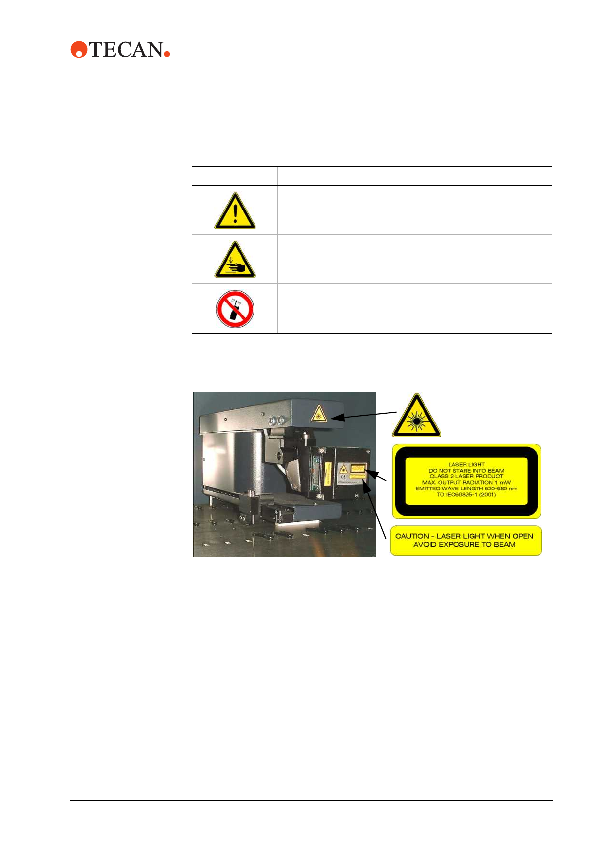
The figure shows the safety notices that are attached to the PosID:
A
B
C
Fig. 2-2 Laser labelling on PosID
Tab. 2-2 Significance of the safety notices on the PosID
Label Significance Location
A Warning label: Laser hazard symbol See Fig. 2-2, 2-5
B Explanatory label: Identifies a CLASS 2 LASER
PRODUCT
low power laser barcode scanner. Warns against
direct viewing into laser beam or its reflections.
CLabel for panels: Warns against removing or
displacing of protective housing/panels, which
permits human access to the laser light.
a) According to IEC60825-1
Freedom EVO Service Manual, 392887, en, V1.3 2 - 5
a)
that contains an embedded visible
See Fig. 2-2, 2-5
See Fig. 2-2, 2-5
2 - Safety
Notices and Symbols
Sensor Plate
Safety Notices
on the Sensor
Plate
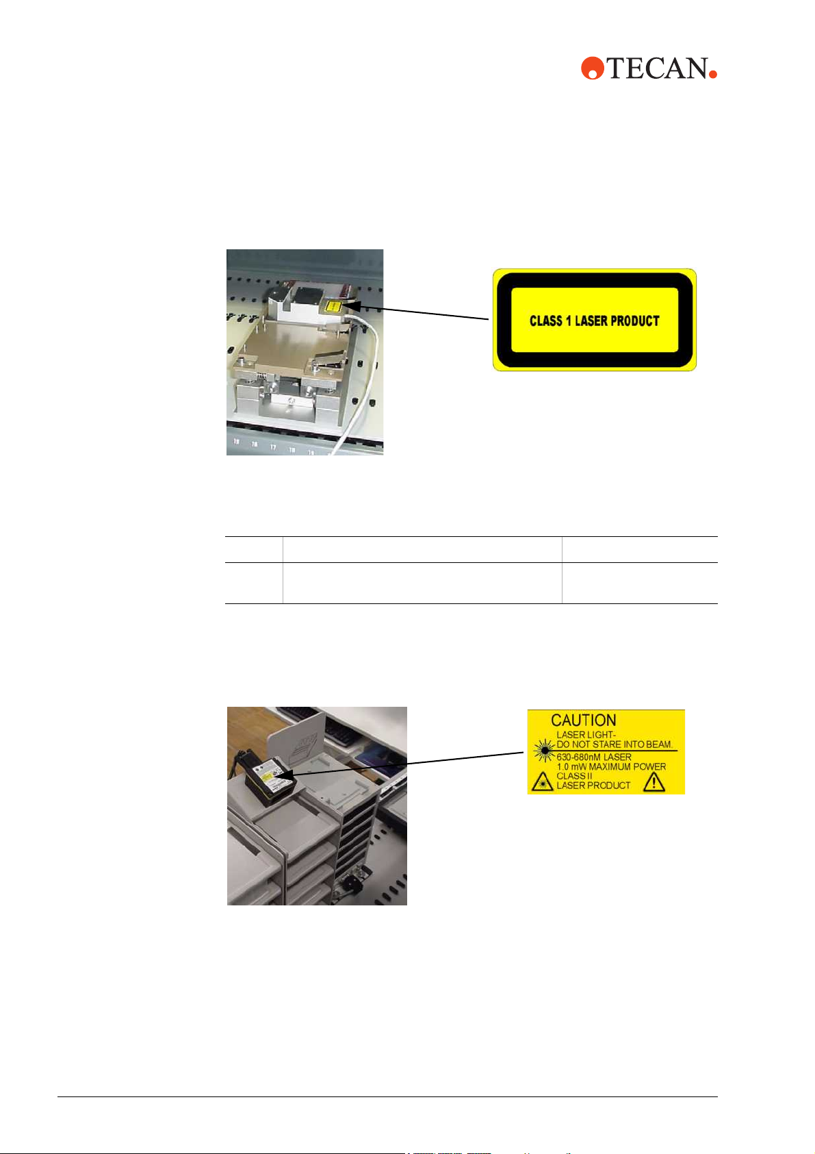
The figure shows the safety notices that are attached to the sensor plate:
Fig. 2-3 Laser labelling on sensor plate
Tab. 2-3 Significance of the safety notices on the sensor plate
Label Significance Location
A Explanatory label:
Identifies a CLASS 1 LASER PRODUCT
a) According to IEC60825-1
a)
See Fig. 2-3, 2-6
A
Safety Notices
on the Symbol
BC Scanner
Symbol BC Scanner
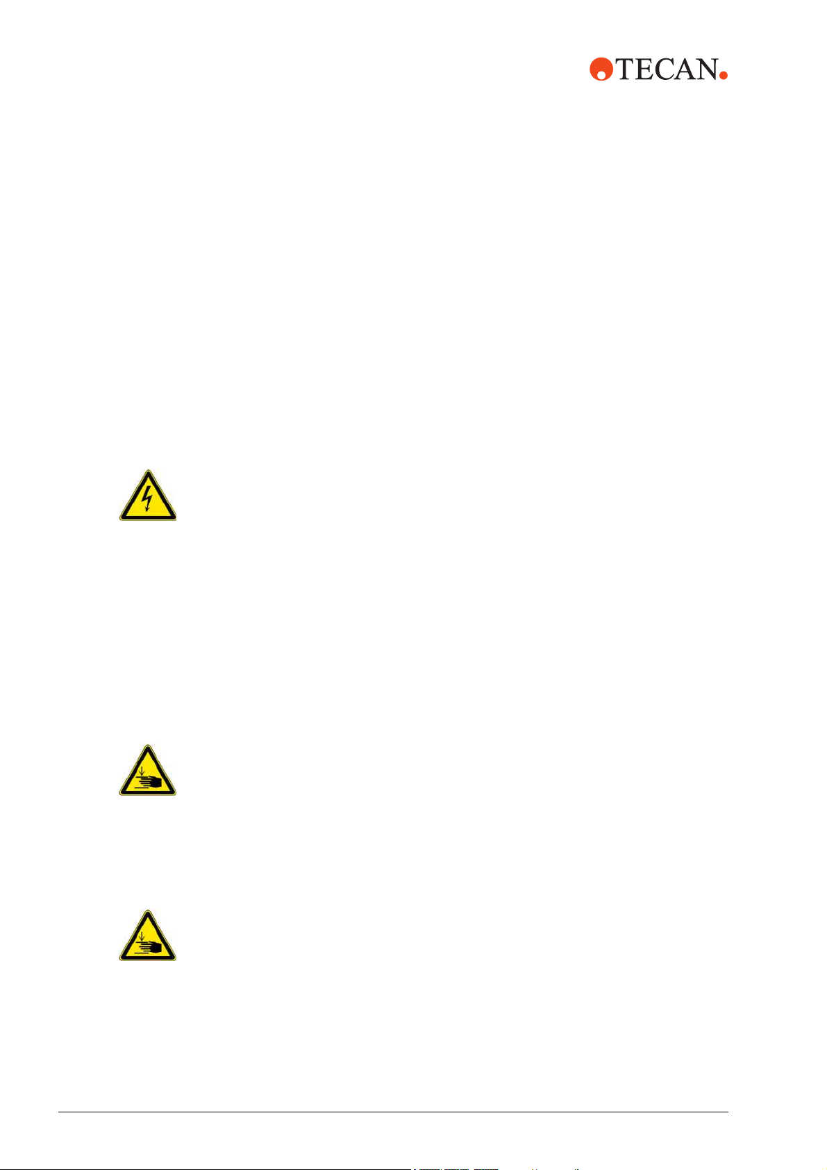
The figure shows the safety notices that are attached to the symbol BC scanner:
A
Fig. 2-4 Laser labelling on the symbol BC scanner
2 - 6 Freedom EVO Service Manual, 392887, en, V1.3

Notices and Symbols
Tab. 2-4 Significance of the safety notices on the symbol BC scanner
Label Significance Location
2 - Safety
A Explanatory label:
Identifies a CLASS 2 LASER PRODUCT
a)
that
See Fig. 2-4, 2-6
contains an embedded visible low power laser
barcode scanner. Warns against direct viewing
into laser beam or its reflections.
a) According to IEC60825-1
Damaged or fallen off symbols (notices or stickers) must be replaced immediately.
Freedom EVO Service Manual, 392887, en, V1.3 2 - 7
2 - Safety
Product Safety
Principle The Freedom EVO is designed and built in accordance with the present state-of-
2.3 Product Safety
the-art technology and the recognized technical safety regulations.
Nevertheless, risks to users, property, and the environment can arise when the
instrument is used carelessly or improperly.
Appropriate warnings in the Operating Manual of the Freedom EVO and in this
Service Manual serve to make the user alert to these residual dangers.
2.3.1 Instrument-Related Hazards and Safety Measures
Pay attention to the following safety notices:
WARNING
Potentially lethal voltage inside the instrument.
Equipment is to be connected to a grounded power source using an approved
power cord with grounding conductor.
Whenever possible, disconnect the instrument from the mains before carrying
out maintenance or repair work.
If work must be carried out with the instrument running, all covers and other
parts protecting from electricity must remain in place.
Though the safety concept assumes that the safety panel is always closed during
normal operation, it is necessary to have access to the elements in the working
area behind the safety panel for setup, maintenance and troubleshooting
purposes.
WARNING
Pointed tips and other sharp-edged elements, which might cause injuries when
you reach into the working area with the safety panel open.
Always be aware of the mechanical hazards.
Wear laboratory apparel, rubber gloves, safety goggles, etc. as appropriate.
WARNING
Freely accessible parts, which can move automatically.
Injuries (piercing and crushing) are possible when you reach into the working area
of the arms or optional equipment during setup and adjustment procedures, or
when tests are run.
Do not reach into the working area when parts of the instrument are moving.
Make sure that no other person activates the drives when the safety covers
are not in place.
2 - 8 Freedom EVO Service Manual, 392887, en, V1.3
2 - Safety
Product Safety
ATTENTION
Unsafe operating condition and wrong measuring results in the process, if the
system is leaking.
If liquid is dripping from the tips or other parts of the liquid system, the
Freedom EVO must not be operated any more.
Operation may only be resumed if the necessary maintenance or repair work has
been performed and the proper condition of the system has been verified.
ATTENTION
Electromagnetic RF waves from a cellular phone may affect the function of the
liquid detection.
Faulty detection of the liquid surface may be the result, which causes the system
to produce incorrect measurements.
Keep a distance of at least 2 m from the instrument when using a cellular phone.
ATTENTION
Damage to the electronic boards due to electrostatic discharge (ESD).
Always wear a wrist strap when handling the boards.
2.3.2 Other Hazards and Safety Measures
Pay attention to the following safety notices:
WARNING
Chemical, biological and radioactive hazards can be associated with the
substances used or the samples processed with the Freedom EVO.
The same applies to waste disposal.
Always be aware of possible hazards associated with these substances.
Use appropriate protective clothing, safety goggles and gloves.
WARNING
Caustic substances can cause burns and eye injury.
Avoid exposure to caustic substances.
Always be aware of possible hazards associated with these substances.
Freedom EVO Service Manual, 392887, en, V1.3 2 - 9
2 - Safety
Product Safety
2.3.3 Safety Elements
Safety Panels The space around the worktable is protected with safety panels. Whereas the
front safety panel can be opened, the other safety panels are permanently
installed on the Freedom EVO.
Door Locks During operation the front safety panel is locked by means of two door locks.
The safety concept of the Freedom EVO assumes that the front safety panel is
always closed when the instrument is running.
Modifications
on the Safety
Panels
Which are
Safety
Elements?
Some options for the Freedom EVO require modifications on the safety panels.
These modifications must be performed by an authorized Tecan FSE (field service
engineer) when the option is installed.
WARNING
If the options which require modifications on the Freedom EVO are installed
improperly, the safety concept may be impaired.
Always make sure that the options are installed in compliance with the instructions
given by the manufacturer.
When installing options, strictly follow the instructions given in the manuals of the
options and in this Service Manual.
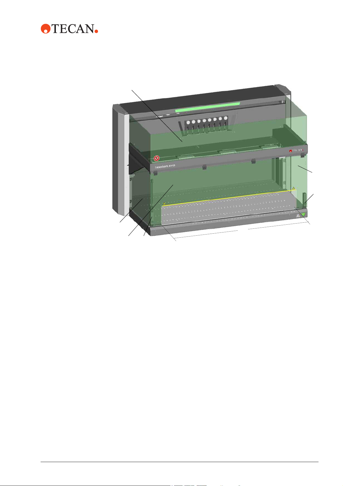
Freedom EVO with Standard Front Safety Panel
The figure shows the elements of the Freedom EVO, which have a protective
function or have in any other way to do with safety:
2 - 10 Freedom EVO Service Manual, 392887, en, V1.3
2 - Safety
A
Product Safety
D
C
C
A B
Fig. 2-5 Safety elements
Standard front safety panel
B Door lock
C Side safety panel
B
X
D Top safety panel
X Cutout for continuous loading
Freedom EVO Service Manual, 392887, en, V1.3 2 - 11
2 - Safety
A
Product Safety
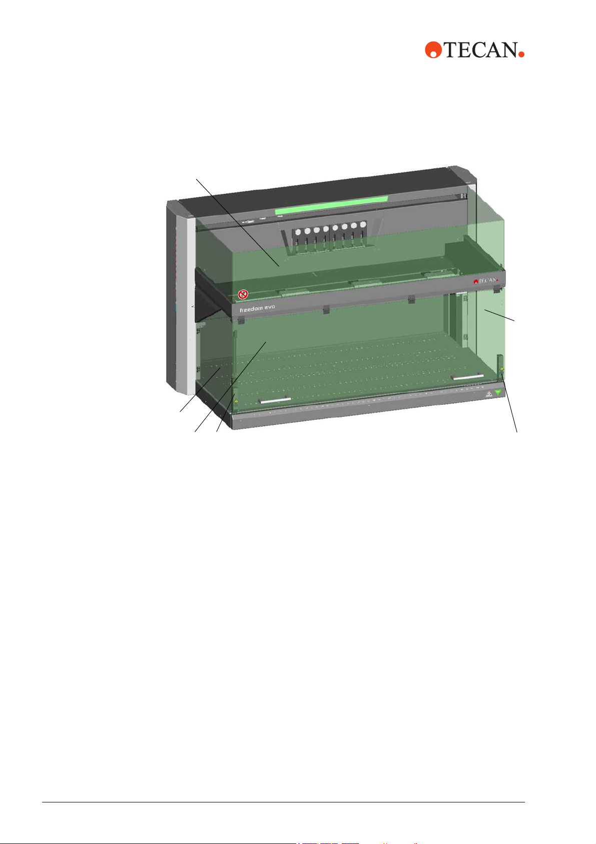
Freedom EVO with Closed Front Safety Panel (Option)
D
C
Removal of
Safety
Elements
C
A
B
B
Fig. 2-6 Safety elements/closed front safety panel (option)
Closed front safety panel
B Door lock
C Side safety panel
D Top safety panel
The protective and safety devices installed on the Freedom EVO must be neither
removed nor disabled during operation.
If such elements were removed, e.g. for maintenance work, operation may only be
resumed when all protective and safety devices have been completely installed
and checked.
2 - 12 Freedom EVO Service Manual, 392887, en, V1.3
2.4 Decontamination
Decontamination
2 - Safety
When to
Decontaminate
Decontamina-
tion Method
Apart from regular decontamination, the user must thoroughly decontaminate the
instrument according to standard laboratory regulations in the following cases:
Before any maintenance or service work is performed on the instrument
In case of accidents (e.g. crash, spilt substances, etc.)
Before a Tecan field service engineer (FSE) performs any in-site work on the
instrument
Before the instrument or parts of it are returned to Tecan (e.g. for repair)
Prior to storage of the instrument
Prior to disposal of the instrument or parts of it
Generally before the instrument or parts of it leave the user’s site
The decontamination method must be adapted to the respective application and
the substances associated with it. The user takes the full responsibility for the
appropriate decontamination of the entire equipment.
WARNING
Biological or chemical hazard and/or radioactive radiation.
Contamination hazard due to parts of the instrument which are not completely
decontaminated.
Mind that not only the parts having direct contact with chemicals or biological
material must be treated, but also the tubing system as well as the whole
upstream equipment.
Decontamina-
tion Form
Before a Tecan FSE carries out any work on the instrument, or before the
instrument is returned to Tecan, the owner of the instrument must confirm in
writing that the decontamination has been performed properly and in accordance
with good laboratory practice guidelines. For this, the owner must enclose a
declaration (Use the Instrument Decontamination Form or in case of repairs,
properly fill out the Repair Order). The corresponding forms are filed in the
Maintenance and Service Logbook or can be provided by Tecan.
Note: Tecan reserves the right to refuse any instrument or a part of it, or will
charge an extra fee, if the Instrument Decontamination Form or the Repair Order
is not filled out and duly signed.
Freedom EVO Service Manual, 392887, en, V1.3 2 - 13

2 - Safety
General Safety Rules
2.5 General Safety Rules
Legal
Regulations
Duty of
Maintenance
and Care
Spare Parts to
Be Used
Modifications Modifications to the Freedom EVO are only permitted after prior consultation with
Legal regulations, such as local, state and federal laws which prescribe the use or
application as well as the handling of dangerous materials in connection with the
Freedom EVO must be strictly followed.
The user is responsible for ensuring that the Freedom EVO is operated in proper
condition only, and that maintenance, service, and repair jobs are performed with
care and on schedule, and by authorized personnel only.
Use only genuine consumables and genuine spare parts for maintenance and
repair to assure good system performance and reliability.
and with the written approval of the manufacturer. Modifications and upgrades
shall only be carried out by an authorized field service engineer. The manufacturer
will decline any claim resulting from unauthorized modifications.
2 - 14 Freedom EVO Service Manual, 392887, en, V1.3
3 Technical Data
Working Area Dimensions
3 - Technical Data
Purpose of This
Chapter
Working Area
Dimensions
This chapter contains supplementary technical data, which is of interest for the
FSE with respect to installation, setup, upgrading and repair of the Freedom EVO.
Note: For common technical data, such as power rating, dimensions, etc., refer to
the “Freedom EVO Operating Manual”.
3.1 Working Area Dimensions
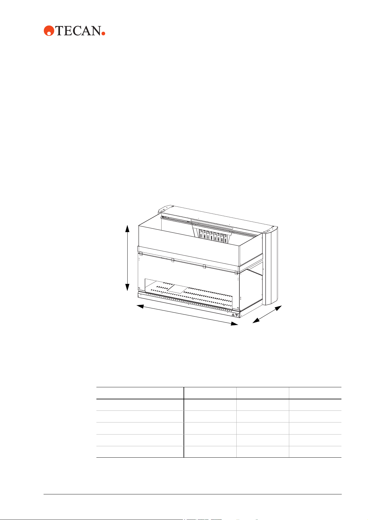
The figure shows the Freedom EVO’s main axes and their designations:
Z
X
Fig. 3-1 Main axes of the Freedom EVO
Y
3.1.1 Ranges in X and Y-Direction
Tab. 3-1 X/Y-ranges
Freedom EVO 100 150 200
Accessible X-range (X-travel) 757 mm (29.8 in.) 1132 mm (44.6 in.) 1732 mm (68.2 in.)
Accessible Y-range (Y-travel)
- 2-tip LiHa, 4-tip LiHa 409 mm (16.1 in.) 409 mm (16.1 in.) 409 mm (16.1 in.)-
- 8-tip LiHa 373 mm (14.7 in.) 373 mm (14.7 in.) 373 mm (14.7 in.)
Grid positions on worktable 30 45 69
Freedom EVO Service Manual, 392887, en, V1.3 3 - 1
3 - Technical Data
A
Working Area Dimensions
Worktable
Cutouts
Z-Range Below
Worktable
Optional, the Freedom EVO (not applicable for Freedom EVO Clinical) can be
equipped with special worktables:
Worktable cutout for centrifuge : 200 x 260 mm (X x Y)
Worktable cutout for reader : 252 x 150 mm (X x Y)
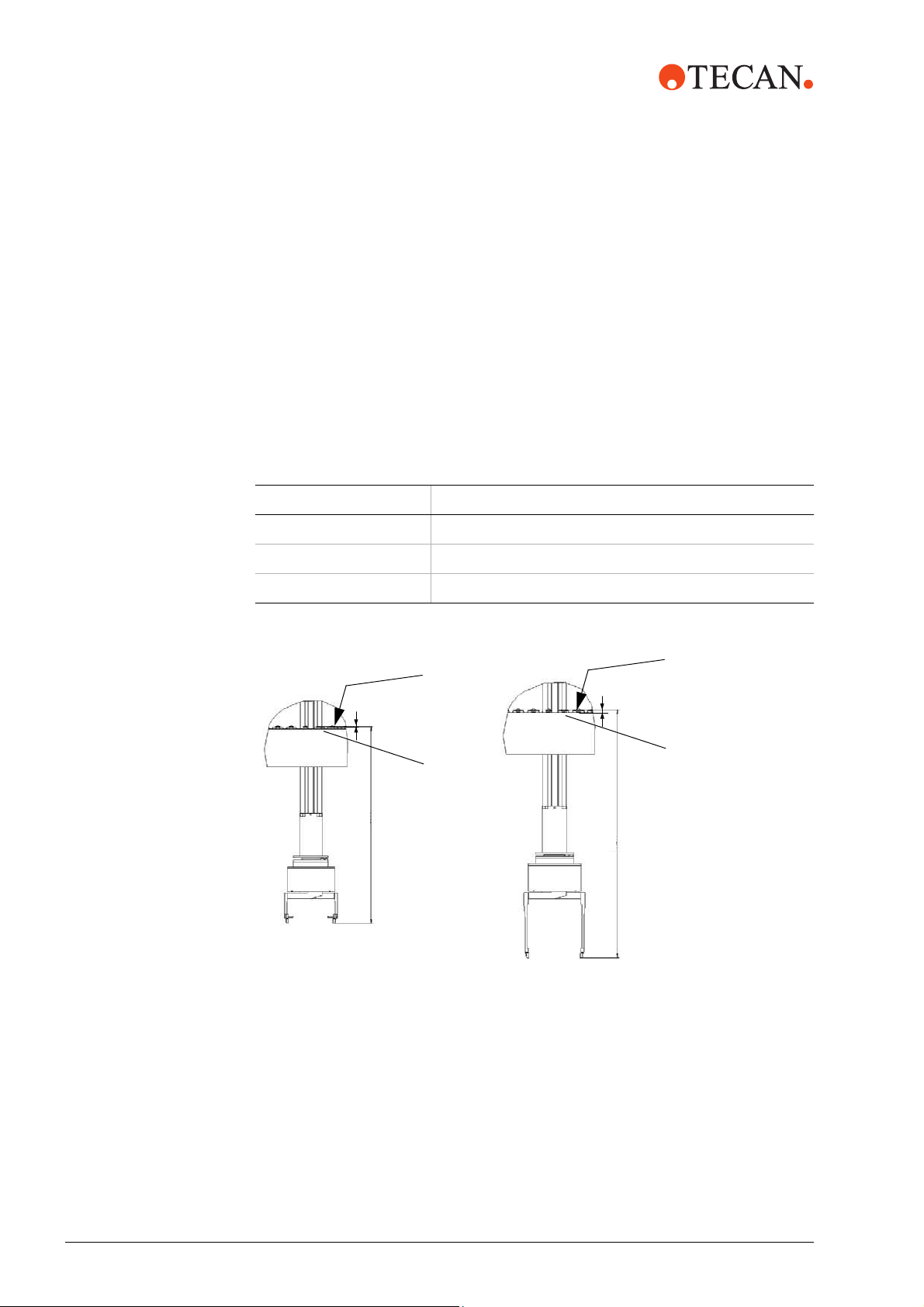
3.1.2 Ranges in Z-Direction
The following table shows the Z-ranges of the different arms (not applicable for
Freedom EVO Clinical):
Tab. 3-2 Z-ranges
Arm Z-range
P&P 385 mm
RoMa Standard 259 mm
RoMa Long 610mm
Eccentric RoMa Fingers
4mm
Centric RoMa Fingers
A
A
4mm
B
B
360.4mm
409mm
Fig. 3-2 Space below worktable
Positioning pin B Worktable
3 - 2 Freedom EVO Service Manual, 392887, en, V1.3
Loading...