


 Loading...
Technical Manual for
SUNRISE RC, TW, TS, TC, BC
Document Part No. T 137 302
February 2002
Document Revision: 1.0
Firmware Revision Level: 3.xx

TECAN Affiliates and Service Centers
Austria |
|
Asia |
Tecan Austria GmbH |
Tecan Asia (Pte) Ltd. |
|
Untersbergstrasse 1a |
80, Marine Parade #13-04 |
|
A-5082 Grödig / Salzburg |
Singapore 449269 |
|
Austria |
|
Singapore |
Tel.: +43 |
62 46 89 33 |
Tel.: +65 44 41 886 |
Fax: +43 |
62 46 72 770 |
Fax: +65 44 41 836 |
Switzerland |
Belgium |
Tecan Schweiz AG |
Tecan Benelux B.V.B.A. |
Seestrasse 103 |
Vaartdijk 55 |
CH-8708 Männedorf |
B-2800 Mechelen |
Switzerland |
Belgium |
Tel.: + 41 1 922 81 11 |
Tel.: +32 15 42 13 19 |
Fax. : +41 1 922 81 12 |
Fax. +32 15 42 16 12 |
France |
Italy |
|
Tecan France S.A. |
Tecan Italia S.r.l. |
|
Parc d'Activités de Pissaloup |
Via F.lli Cervi |
|
Batiment Hermes II |
Palazzo Bernini |
|
Rue Edouard Branly |
Centro Direzionale Milano2 |
|
F-78190 Trappes |
20090 Segrate (Mi) |
|
France |
Italy |
|
Tel.: +33 1 30 68 81 50 |
Tel.: +39 |
02 215 21 28 |
Fax: +33 1 30 68 98 13 |
Fax: +39 |
02 215 97 441 |
Japan |
USA |
Tecan Japan Co. Ltd |
Tecan US |
Meiji Seimei Fuchu Building 10F |
P.O. Box 13953 |
1-40 Miyamachi |
Research Triangle Park, |
Fuchu City, Tokyo |
NC 27709 |
Japan |
USA |
Tel.: +81 42 334 88 55 |
Tel.: +1 919 361 5200 |
Fax: +81 42 334 04 01 |
Fax: +1 919 361 5201 |
Spain |
Germany |
|
Tecan Spain |
Tecan Deutschland GmbH |
|
Sabino de Arana, 32 |
Theodor-Strom-Straße 17 |
|
E-08028 Barcelona |
D-74564 Crailsheim |
|
Spain |
Germany |
|
Tel.: +34 93 490 01 74 |
Tel.: +49 |
79 51 94 170 |
Fax: +34 93 411 24 07 |
Fax: +49 |
79 51 50 38 |
USA |
Netherlands |
Tecan Boston |
Tecan Benelux B.V.B.A. |
200 Boston Avenue |
Industrieweg 30, |
Suite 3000 |
NL-4283 Giessen, |
Medford, MA 02155 |
Netherlands; |
USA |
Tel.: +31 018 34 48 17 4 |
Tel.: +1 781 306 08 27 |
Fax: +31 018 34 48 06 7 |
Fax: +1 781 306 0837 |
|
United Kingdom |
|
Tecan UK |
|
Theale Court |
|
11-13 High Street |
|
Theale |
|
UK-Reading RG7 5AH |
|
United Kingdom |
|
Tel.: +44 11 89 300 300 |
|
Fax: +44 11 89 305 671 |
|
2 |
Technical Manual for SUNRISE RC, TW, TS, TC, BC No: T 137 302 Rev No: 1.0 |
February 2002 |

WARNING
CAREFULLY READ AND FOLLOW THE INSTRUCTIONS
PROVIDED IN THIS MANUAL BEFORE OPERATING THE
INSTRUMENT.
Notice
Every effort has been made to avoid errors in text and diagrams, however, TECAN Austria Ges.m.b.H. assumes no responsibility for any errors which may appear in this publication.
It is the policy of TECAN Austria Ges.m.b.H. to improve products as new techniques and components become available.TECAN Austria Ges.m.b.H. therefore reserves the right to change specifications at any time.
We would appreciate any comments on this publication. TECAN Austria Ges.m.b.H.
Untersbergstraße 1A A-5082 Grödig/Salzburg AUSTRIA / EUROPE
Telephone: 0043 (0)6246/8933 FAX: 0043 (0) 6246/72770 E-mail: office.austria@tecan.com
Copyright Information
The contents of this manual are the property of TECAN Austria Ges.m.b.H and are not to be copied, reproduced or transferred to another person or persons without our prior written permission.
Copyright TECAN Austria Ges.m.b.H All rights reserved.
Printed in Austria.
February 2002 |
Technical Manual for SUNRISE RC, TW, TS, TC, BC No: T 137 302 Rev No: 1.0 |
3 |
Warnings, Cautions and Notes
There are three types of informational notices used in this manual. These notices highlight important information or warn the user of a potentially dangerous situation. The following notices are:
Note: Gives helpful information.
Caution
Indicates a possibility of instrument damage or data loss if instructions are not followed.
WARNING
INDICATES THE POSSIBILITY OF SEVERE PERSONAL INJURY,
LOSS OF LIFE OR EQUIPMENT DAMAGE IF THE INSTRUCTIONS
ARE NOT FOLLOWED.
4 |
Technical Manual for SUNRISE RC, TW, TS, TC, BC No: T 137 302 Rev No: 1.0 |
February 2002 |

Table of Contents
1. General |
|
|
1.1 |
Introduction ............................................................................... |
1-1 |
|
Abbreviations:.............................................................................. |
1-1 |
1.1.1 |
Available Options for SUNRISE .................................................. |
1-2 |
1.2 |
Instrument Description ............................................................. |
1-3 |
1.2.1 |
Remote Control ........................................................................... |
1-3 |
1.2.2 |
Touchscreen................................................................................ |
1-3 |
1.2.3 |
Back Panel Connections ............................................................. |
1-4 |
1.3 |
Filter Carriage Description ....................................................... |
1-5 |
1.3.1 |
SUNRISE Standard Filter Carriage ............................................. |
1-5 |
1.3.2 |
Sunrise Tuneable Wavelength Filter Carriage............................. |
1-5 |
1.3.3 |
Software Features ....................................................................... |
1-6 |
1.4 |
Instrument Features.................................................................. |
1-6 |
1.4.1 |
Measurement Modes................................................................... |
1-6 |
1.4.2 |
Microplate Shaking...................................................................... |
1-7 |
1.5 |
Instrument Accessories............................................................ |
1-7 |
|
Computer Software for Personal Computer ................................ |
1-7 |
2. |
Installation Procedure |
|
|
|
2.1 |
Introduction ............................................................................... |
2-1 |
|
2.2 |
Unpacking and Inspection........................................................ |
2-1 |
|
2.2.1 |
Unpacking Procedure.................................................................. |
2-2 |
|
2.3 |
Power Requirements................................................................. |
2-2 |
|
2.4 |
Environmental Requirements................................................... |
2-2 |
|
2.5 |
Instrument Installation Procedure ........................................... |
2-3 |
|
2.5.1 |
Installation of Instrument Control Software.................................. |
2-3 |
3. Firmware and Software Description |
|
||
|
3.1 |
Rdr Download Software............................................................ |
3-1 |
|
3.1.1 |
Starting the Firmware Download ................................................. |
3-2 |
|
3.1.2 |
Open file ...................................................................................... |
3-3 |
|
3.2 |
Rdr OLE Server.......................................................................... |
3-4 |
|
3.2.1 |
Installation of Instrument Control Software.................................. |
3-4 |
|
3.3 |
Sunrise Instrument Settings .................................................... |
3-4 |
|
3.3.1 |
Installation of SUNRISE Instrument Settings Software ............... |
3-4 |
|
3.3.2 |
Starting the SUNRISE Instrument Settings ................................. |
3-5 |
|
3.3.3 |
Define Instrument Mode .............................................................. |
3-5 |
|
3.3.4 |
Define Filter ................................................................................. |
3-6 |
|
3.3.5 |
Define Measurement Mode ......................................................... |
3-7 |
|
3.4 |
SunSet Software (Service tool kit is necessary!) ................... |
3-8 |
|
3.4.1 |
Installation of SUNSET Software................................................. |
3-8 |
|
3.4.2 |
Starting the SunSet Software ...................................................... |
3-8 |
|
3.4.3 |
Device configuration.................................................................. |
3-10 |
|
3.4.4 |
Mirror and lamp adjustment....................................................... |
3-10 |
|
3.4.5 |
Plate calibration......................................................................... |
3-11 |
|
3.4.6 |
Measurement offset (Inhouse plate is necessary)..................... |
3-12 |
|
3.4.7 |
User configuration ..................................................................... |
3-13 |
|
3.4.8 |
SunSet Options Menu ............................................................... |
3-14 |
|
|
Filter control............................................................................... |
3-14 |
|
|
|
|
February 2002 |
Technical Manual for SUNRISE RC, TW, TS, TC, BC No: T 137 302 Rev No: 1.0 |
5 |
|

|
Plate Movements....................................................................... |
3-15 |
|
Duration test .............................................................................. |
3-15 |
3.5 |
Sunrise Diagnosis Tool .......................................................... |
3-16 |
3.5.1 |
Installation of Sunrise Diagnosis Tool ....................................... |
3-16 |
3.5.2 |
Connect instrument ................................................................... |
3-17 |
3.5.3 |
Get Diagnosis Information......................................................... |
3-18 |
3.5.4 |
Duration test .............................................................................. |
3-18 |
3.5.5 |
Print report................................................................................. |
3-19 |
3.6 |
Error messages ....................................................................... |
3-19 |
4. Removing and Replacing the Instrument Cover
4.1 |
Removal of Instrument Top Cover........................................... |
4-1 |
4.2 |
Removal of the Front Cover ..................................................... |
4-3 |
4.3 |
Replacing the Front Cover ....................................................... |
4-4 |
4.4 |
Replacing the instrument top cover ........................................ |
4-4 |
4.5 |
Removal of Touchscreen.......................................................... |
4-5 |
5. Optical System
5.1 |
Introduction ............................................................................... |
5-1 |
5.2 |
Optical System Description...................................................... |
5-1 |
5.3 |
Optical System Diagram ........................................................... |
5-2 |
|
SUNRISE ST (Option Standard Optic) Instrument...................... |
5-2 |
|
SUNRISE TW (Tuneable Wavelength Optic) Instrument ............ |
5-2 |
5.3.1 |
Measurements with Wavelengths below 400 nm ........................ |
5-3 |
5.3.2 |
Agglutination Measurement Mask for SUNRISE ST Option........ |
5-3 |
5.4 |
Lamp Replacement ................................................................... |
5-4 |
5.5 |
Filter Slide .................................................................................. |
5-5 |
5.5.1 |
SUNRISE Filter Slide (standard filter slide)................................. |
5-5 |
5.5.2 |
Replacement of Filters in SUNRISE Filter Slides........................ |
5-6 |
5.5.3 |
Filter Coding for SUNRISE Filter Slides ...................................... |
5-7 |
5.5.4 |
Definition of the filter slide codes:................................................ |
5-8 |
|
Slide D......................................................................................... |
5-8 |
5.6 |
Filter slide ( Tuneable wavelength).......................................... |
5-9 |
5.7 |
Lamp and Mirror Unit Parts .................................................... |
5-11 |
5.7.1 |
Heat Filter and Air Filter ............................................................ |
5-11 |
5.7.2 |
Mirror, Optical Lens ................................................................... |
5-12 |
|
For Mirror Replacement: ........................................................... |
5-12 |
|
For Optical Lens Replacement.................................................. |
5-13 |
5.8 |
Filter Guide (standard instrument ) ....................................... |
5-13 |
5.9 |
Filter Guide ( Tuneable Wavelength):.................................... |
5-15 |
5.10 |
Fiber Bundle ............................................................................ |
5-16 |
5.10.1Difference between Standard Fiber Optic and Tuneable Wavelength
|
Fiber Optic................................................................................. |
5-17 |
5.11 |
Further Parts belonging to the Optical System.................... |
5-17 |
5.12 |
Blocking Filter Wheel for Tuneable Wavelength .................. |
5-18 |
5.13 |
Filter Wheel Properties ........................................................... |
5-19 |
5.14 |
Mirror for Barcode Scanner.................................................... |
5-19 |
6 |
Technical Manual for SUNRISE RC, TW, TS, TC, BC No: T 137 302 Rev No: 1.0 |
February 2002 |

6. Mechanical System |
|
|
6.1 |
Introduction ............................................................................... |
6-1 |
6.2 |
Transport System Description ................................................. |
6-1 |
6.3 |
Measurement Procedure .......................................................... |
6-1 |
|
Inside Shaking............................................................................. |
6-2 |
6.4 |
The Transport Box Assembly .................................................. |
6-2 |
6.5 |
Exchanging the Transport Box ................................................ |
6-3 |
6.6 |
Transport Box Adjustments ..................................................... |
6-5 |
6.7 |
Replacing the Temperature control unit ................................. |
6-5 |
7. Electronic System |
|
|
7.1 |
Introduction ............................................................................... |
7-1 |
7.2 |
Interconnection diagram (standard RC).................................. |
7-2 |
7.3 |
Voltage diagram (standard RC)................................................ |
7-3 |
7.4 |
Main Board................................................................................. |
7-4 |
7.5 |
Replacing the Main Board ........................................................ |
7-5 |
7.6 |
Power Board (standard)............................................................ |
7-7 |
7.7 |
Exchanging the Power Board (standard)................................ |
7-8 |
7.8 |
Power Board (tuneable wavelength)........................................ |
7-9 |
7.9 |
TW Board ................................................................................ |
7-11 |
7.10 |
Thermo Board.......................................................................... |
7-12 |
7.11 |
12 Volt Board ........................................................................... |
7-13 |
7.12 |
Power Supply board................................................................ |
7-14 |
7.13 |
Replacing the Power Supply .................................................. |
7-15 |
7.14 |
Barcode Board......................................................................... |
7-16 |
7.15 |
Optical Switches...................................................................... |
7-17 |
8. |
Interfaces |
|
|
|
8.1 |
Computer Interface ................................................................... |
8-1 |
|
8.1.1 |
Hardware Specifications.............................................................. |
8-1 |
|
8.1.2 |
Pin Designation ........................................................................... |
8-1 |
|
8.1.3 |
RS-232-C Interface Lines............................................................ |
8-2 |
|
|
Requirements for the Serial Interface:......................................... |
8-2 |
|
|
Description of the serial Interface:............................................... |
8-3 |
|
|
Implemented RS-232-C Interface Lines : .................................... |
8-3 |
|
|
Available Setups:......................................................................... |
8-3 |
|
8.2 |
Handshakes: .............................................................................. |
8-4 |
|
|
Software Handshake: .................................................................. |
8-4 |
|
8.3 |
Commands Response Time: .................................................... |
8-4 |
|
8.4 |
Command Syntax for the Serial Interface:.............................. |
8-4 |
|
|
Sunrise Mode (Standard): ........................................................... |
8-4 |
|
|
Spectra Mode (for compatibility):................................................ |
8-4 |
|
8.5 |
Synchronization and Data Format ........................................... |
8-5 |
|
8.6 |
Signal Levels ............................................................................. |
8-5 |
|
8.7 |
Software Specifications............................................................ |
8-6 |
|
8.8 |
Handshake ................................................................................. |
8-6 |
|
8.9 |
Timing Of Messages ................................................................. |
8-6 |
|
8.10 |
Communication Messages ....................................................... |
8-6 |
|
8.11 |
Printer Interface......................................................................... |
8-7 |
|
8.11.1 |
Character Set Setting .................................................................. |
8-7 |
|
8.11.2 |
Hardware Specifications.............................................................. |
8-7 |
|
|
|
|
February 2002 |
Technical Manual for SUNRISE RC, TW, TS, TC, BC No: T 137 302 Rev No: 1.0 |
7 |
|

8.11.3 |
Connector.................................................................................... |
8-7 |
8.12 |
Parallel Interface Lines ............................................................. |
8-8 |
8.13 |
Table of Connections................................................................ |
8-8 |
8.14 |
Key to Table ............................................................................... |
8-9 |
|
Connector Pin Signals................................................................. |
8-9 |
|
Strobe.......................................................................................... |
8-9 |
|
Data 1 - Data 8 ............................................................................ |
8-9 |
|
Acklng - Acknowledge ................................................................. |
8-9 |
|
Busy ............................................................................................ |
8-9 |
8.15 |
Connection with Touchscreen interface connector............. |
8-10 |
8.15.1 |
XChange Files:.......................................................................... |
8-10 |
9. Sunrise Service Tool Kits for Sunrise RC and Options
9.1 |
Service tool kit 1 (S 039 341) .................................................... |
9-1 |
9.1.1 |
Introduction.................................................................................. |
9-1 |
9.2 |
Installation Procedure............................................................... |
9-2 |
9.3 |
Sunrise Diagnosis Software..................................................... |
9-2 |
9.3.1 |
Explanation of the Output of the Sunrise Diagnosis Tool........... |
9-3 |
9.4 |
Sunrise SUNSET Software ....................................................... |
9-6 |
9.5 |
QC Pac 2 Service software:...................................................... |
9-7 |
9.6 |
Flashcard Download (S039351) ............................................... |
9-8 |
9.7 |
Flashcard for Touchscreen unit............................................... |
9-8 |
9.8 |
Barcode Upgrade Kit................................................................. |
9-9 |
9.8.1 |
General........................................................................................ |
9-9 |
9.8.2 |
Installation ................................................................................. |
9-10 |
9.8.3 |
Hardware Installation................................................................. |
9-12 |
9.8.4 |
Software Installation and Adjustment ........................................ |
9-15 |
9.9 |
Overview of Single commands: ............................................. |
9-22 |
10. Maintenance
10.1 |
Instrument Disinfection .......................................................... |
10-1 |
10.2 |
Disinfection Solutions ............................................................ |
10-1 |
10.3 |
Disinfection Procedure ........................................................... |
10-2 |
10.4 |
Disinfection Certificate ........................................................... |
10-2 |
10.5Preventative Maintenance Plan for SUNRISE Instruments .10-3
10.5.1 |
Daily .......................................................................................... |
10-3 |
10.5.2 |
Weekly....................................................................................... |
10-3 |
10.5.3 |
Every Six Months ...................................................................... |
10-3 |
10.5.4 |
Yearly (Service Technician Required)....................................... |
10-3 |
10.5.5 |
Every Four Years ...................................................................... |
10-3 |
10.6 |
Electrostatic Discharge Information...................................... |
10-4 |
10.6.1 |
Generating Static....................................................................... |
10-4 |
10.6.2 |
Preventing Electrostatic Damage to Equipment........................ |
10-5 |
10.6.3 |
Personal Grounding Methods.................................................... |
10-5 |
8 |
Technical Manual for SUNRISE RC, TW, TS, TC, BC No: T 137 302 Rev No: 1.0 |
February 2002 |

11. Performance Testing / Quality Control
11.1 |
Introduction ............................................................................. |
11-1 |
11.2 |
Operating for Maximum Performance ................................... |
11-1 |
11.2.1 |
Instrument Location................................................................... |
11-1 |
11.2.2 |
Operating Procedure ................................................................. |
11-2 |
11.2.3 |
Self Check Procedure ............................................................... |
11-2 |
11.3 |
Performance Tests .................................................................. |
11-2 |
11.3.1 |
QC PAC 2.................................................................................. |
11-3 |
11.3.2 |
Microplate Test.......................................................................... |
11-3 |
11.3.3 |
High Meniscus Liquids .............................................................. |
11-4 |
|
Agglutination Method................................................................. |
11-5 |
|
Manual Method.......................................................................... |
11-6 |
|
Example .................................................................................... |
11-6 |
11.4 |
Quality Control Testing........................................................... |
11-7 |
11.4.1 |
Precision Testing....................................................................... |
11-7 |
11.4.2 |
Instrument Accuracy.................................................................. |
11-8 |
11.4.3 |
Instrument Linearity................................................................... |
11-9 |
12. Trouble Shooting
12.1 Introduction .............................................................................12-1
13. Parts for Sunrise
February 2002 |
Technical Manual for SUNRISE RC, TW, TS, TC, BC No: T 137 302 Rev No: 1.0 |
9 |
1. General
1. General
1.1 Introduction
SUNRISE Remote Control is intended for use with only external software.
Sunrise with TS Option is intended for use with external software and in Stand alone mode.
The SUNRISE instruments are fully automatic, microprocessor controlled readers designed for professional use, enabling the user to measure the light absorbency (optical density) of samples in 96 well microplates according to the specifications described in this manual.
Abbreviations:
RC |
Remote control |
TW |
Tuneable wavelength option |
TS |
Touchscreen option |
TC |
Temperature control option |
BC |
Barcode option |
Results obtained using the SUNRISE are influenced by the proper use of the instrument, according to the instructions given in this manual, as well as the liquid compounds used (reagents, chemistry). The instructions for use, storage and other manipulations in connection with samples or reagents have to be strictly followed. Taking this fact into consideration, results must be interpreted carefully.
By reading twelve wells simultaneously, the instrument is able to measure a microplate in approximately eight seconds using the dual wavelength method.
With an innovative range of options, this versatile MTP reader gives diagnostic and research laboratories all the features for numerous purposes.
Based on a new design concept EPAC, the excellent optical performance and high quality of the SUNRISE will guarantee fast, reproducible and accurate measurements.
The SUNRISE is designed to be fitted into TECAN robotic systems.
February 2002 |
Technical Manual for SUNRISE RC, TW, TS, TC, BC No: T 137 302 Rev No: 1.0 |
1-1 |
1. General
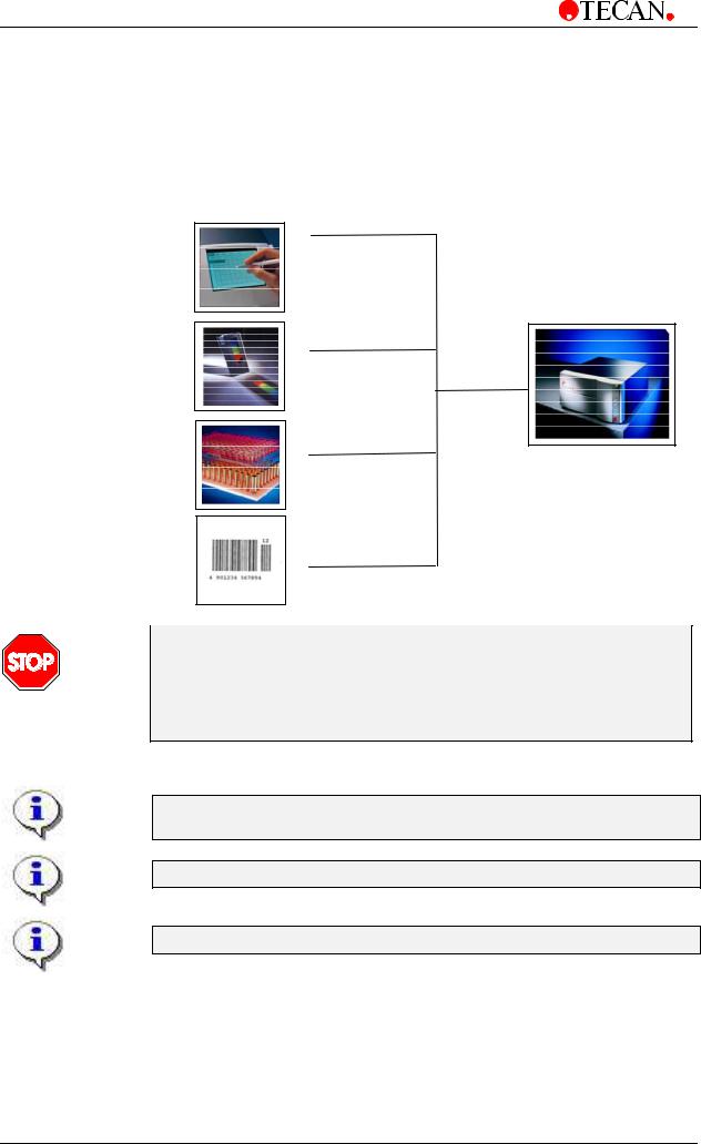
1.1.1Available Options for SUNRISE
The Sunrise is a modular system, so you can create your own tailor-made instrument that meets exactly your needs. Options such as a touch screen combined with a WindowsCE based on-board software, free wavelength selection, temperature control and a bar code scanner can be added onto the basic system which is dedicated to remote controlled computer operation.
Touchscreen
B037302
SUNRISE
Remote Controlled
Tuneable wavelength from 400 – 700 nm
B037306
Temperature control
B037303
Barcode scanner
B037304
CAUTION
IF THE INSTRUCTIONS GIVEN IN THIS MANUAL ARE NOT CORRECTLY CARRIED OUT, THE INSTRUMENT MAY EITHER BECOME DAMAGED OR MAY NO LONGER BE ABLE TO PERFORM ITS PROCEDURES CORRECTLY AND THE ACCURACY OF THE INSTRUMENT
CAN NO LONGER BE GUARANTEED.
For more information about the operating instructions, see Magellan or XRead Plus manuals.
The available options are Retro-fit by TECAN Austria only.*
FOLLOW LASER SPECIFICATIONS (see 1.3 back panel connections)
*Except Barcode Upgrade Kit S 039 386 Only by TECAN certified FSE
1-2 Technical Manual for SUNRISE RC, TW, TS, TC, BC No: T 137 302 Rev No: 1.0 |
February 2002 |
1. General
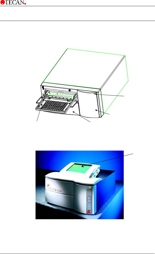
1.2 Instrument Description
The illustrations below show the components of the instruments.
1.2.1Remote Control
|
Power ON LED |
|
Lamp Compartment |
Plate Support |
Cartridge and Filter Block Compartment |
1.2.2Touchscreen
Touchscreen
Sunrise
 Memo Card
February 2002 |
Technical Manual for SUNRISE RC, TW, TS, TC, BC No: T 137 302 Rev No: 1.0 |
1-3 |
1. General
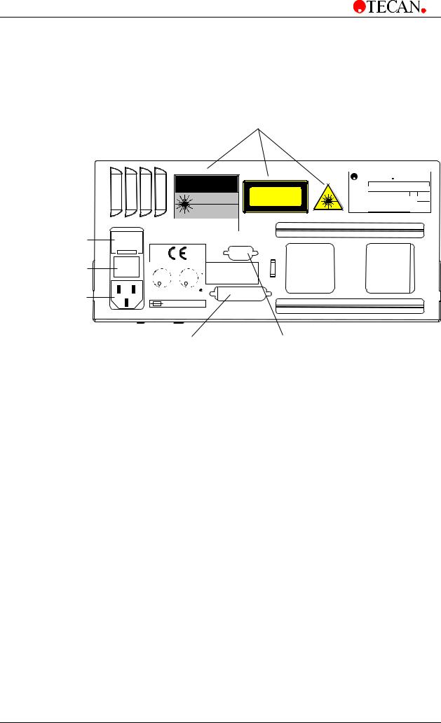
1.2.3Back Panel Connections
The illustration below shows the connections located in the back panel of the instrument.
BarCode Laser Scanner labels ( only with the barcode option )
|
|
|
CAUTION |
LASERSTRAHLUNG |
|||
|
|
|
|
|
|
|
NICHT IN DEN STRAHL BLICKEN |
|
|
|
|
|
|
|
LASER KLASSE 2 |
|
|
|
|
LASER RADIATION - |
|
Leistung: <1mW |
|
|
|
|
|
|
Wellenlänge: 675nm |
||
|
|
|
|
|
|
|
EN60825-1:1994+A11:1996 |
|
|
|
|
DO NOT STARE INTO BEAM |
|||
|
|
|
|
CLASS II LASER PRODUCT |
|||
|
|
|
|
Complies with 21CFR |
|
|
|
|
|
|
|
and 1040.10 and 1040.11 |
|
|
|
Instruments Main Fuses |
|
|
|
|
|
|
|
ON / OFF Switch |
I |
LISTED |
|
|
|
|
RS 232 |
0 |
|
|
|
|
|||
|
UR L C |
|
UR L |
TECAN |
PRINTER |
||
|
|
|
|||||
Mains Socket |
|
8C64 |
|
|
|
|
|
|
LABORATORY EQUIPMENT |
|
|
||||
|
|
2 x F2A |
|
|
|
||
TECAN |
A-5082 AUSTRIA |
|
TECAN |
TYPE |
Sunrise |
|
|
ART.-NR. |
F0393xx |
VA |
110 |
SER.-NR. |
xxxxx |
Hz |
50 / 60 |
VOLTAGE AC 100 - 120 / 220 - 240 |
|
MADE IN |
|
M-CODE |
xxxxxx |
|
|
|
AUSTRIA |
||
Printer Connector |
Serial RS 232 Connector |
( Only functions with |
|
the touch screen option ) |
|
All connected devices must be approved and listed as per EN 60950, UL 1950 or CSA C22.2 No. 950 for Data Processing Devices
1-4 Technical Manual for SUNRISE RC, TW, TS, TC, BC No: T 137 302 Rev No: 1.0 |
February 2002 |
1. General
1.3 Filter Carriage Description
The SUNRISE instrument can use the following types of filter carriages:
SUNRISE Standard and SUNRISE Gradient Filter (with tuneable wavelength option).
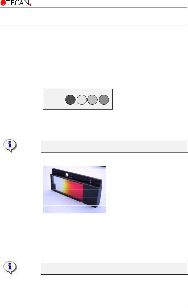
1.3.1SUNRISE Standard Filter Carriage
The SUNRISE standard filter carriage is fitted with up to four narrow band interference filters which have a fixed wavelength.
SUNRISE Standard Filter Carriage
When a wavelength is selected, the entered wavelength is compared against the list of entered filter values for this filter carriage.
If the required filter is fitted in the filter carriage, the filter carriage is moved so that the required filter is in the light beam.
For more information about the definition of the new and customized filter slides, see 3.8 Define Filter.
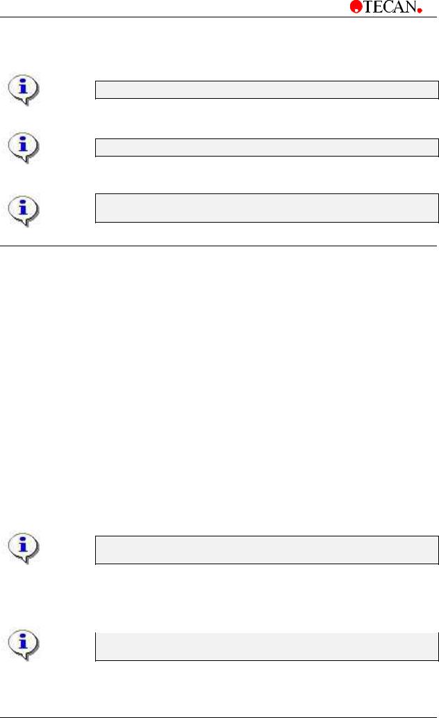
1.3.2Sunrise Tuneable Wavelength Filter Carriage
•Over 300 wavelengths available from one Gradient filter slide.
•Complete Spectrum scanning - useful for screening new or unknown compounds
•UV light range available on standard filter slide
•High flexibility in one instrument
SUNRISE TW functions only with the Blocking Filter Wheel
See Chapter 5.12 Blocking Filter Wheel for Tuneable Wavelength.
February 2002 |
Technical Manual for SUNRISE RC, TW, TS, TC, BC No: T 137 302 Rev No: 1.0 |
1-5 |
1. General
1.3.3Software Features
SUNRISE Remote Control is intended for use with only external software.
Sunrise Touchscreen is a stand alone device, that works with windows CE.
For more information about the software features, see the appropriate individual manuals. For example: refer to the Magellan Reference manual.
1.4 Instrument Features
Microplates can be measured using the following features:
•Various measurement modes
•Single or dual wavelength measurements
•Microplate shaking
•Temperature controlled Incubation
1.4.1Measurement Modes
The instrument can be set to use the following measurement modes:
Fast |
Plate transport is moved quickly under the measurement diodes so |
|
that a fast measurement is obtained. (Default setting). |
Accurate |
Plate transport is moved slowly under the measurement diodes so |
|
that a very accurate measurement is obtained. |
Center |
This option measures the optical density only at the center of the |
|
well. |
With the Fast and Accurate measurement modes, the optical density is measured at three positions across the wells and the average measured optical density value from the three measurements is used as the optical density of the well.
The accurate measurement cycle should always be used when measuring high optical densities.
The Center measurement mode should be used if the liquid in the microplate produces a high meniscus, as an incorrect optical density could be obtained if the optical density is measured at three positions. If an Agglutination measurement is performed, all the measurement positions are used.
For more information about setting the measurement mode, see 3.9 Defining the SUNRISE Instrument Settings.
1-6 Technical Manual for SUNRISE RC, TW, TS, TC, BC No: T 137 302 Rev No: 1.0 |
February 2002 |

1. General
1.4.2Microplate Shaking
The SUNRISE is able to shake the microplate before it is measured. Use external software (for example: Magellan) to set the shaking modes.
The microplate can also be shaken between each of the kinetic measurement cycles.
When using a 96 well plate, spillage may occur if the wells are filled with more than 300µl, while using high shaking mode.
1.5 Instrument Accessories
The table below contains the order numbers for instrument accessories:
Part Name |
Part Order Number |
|
Halogen lamp................................................................................. |
3 |
709 008 |
Reader to external computer cable................................................ |
3 |
350 005 |
QC Pac 2 for SUNRISE and SPECTRA ........................................ |
B 037 358 |
|
Additional filter slide ....................................................................... |
B 036 301 |
|
Memory card ............................................................................. |
B 037 359 01 |
|
Flash card for Magellan Windows CE (English) ............................ |
S 039 351 |
|
TS - Pen ......................................................................................... |
B 037 360 |
|
Barcode Upgrade Kit...................................................................... |
S 039 386 |
|
Sunrise Service tool kit .................................................................. |
S 039 341 |
|
Computer Software for Personal Computer
Related Software
Part of Reader PC Package:
Software |
Functionality |
|
|
Magellan |
Instrument control and data reduction |
XRead Plus |
Instrument control and transfer of raw data to |
|
Excel. |
SUNRISE instrument setting |
Enables settings of SUNRISE instrument |
|
(SUNRISE, SPECTRA, ATC mode and so on). |
RDR Download |
Enables Download of new firmware from PC to |
|
reader. |
SUNRISE Error Diagnosis |
Creates printout of instrument status for service |
|
purposes. |
Sunset Software |
For servicing the sunrise and performing all |
|
instrument adjustments |
|
(only for trained/ certified persons!) |
February 2002 |
Technical Manual for SUNRISE RC, TW, TS, TC, BC No: T 137 302 Rev No: 1.0 |
1-7 |
2. Installation Procedure
2. Installation Procedure
2.1 Introduction
This chapter contains the necessary information for installing the instrument.
The installation procedures involve unpacking, environmental requirements, power requirements and interfacing.
2.2 Unpacking and Inspection
The delivered instrument is shipped in one carton, which includes: Power cable
Computer connection cable
SUNRISE Operating manual, XRead Plus manual Spare fuses
A software CD, which also contains the XRead Plus program and Magellan demo program (30 day working license).
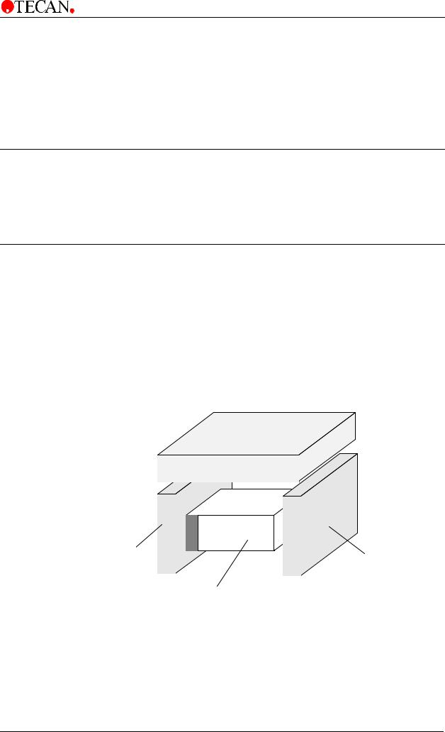
Accessory box
Foam Packaging |
Foam |
|
|
|
Packaging |
|
Instrument |
February 2002 |
Technical Manual for SUNRISE RC, TW, TS, TC, BC No: T 137 302 Rev No: 1.0 |
2-1 |
2. Installation Procedure
2.2.1Unpacking Procedure
1.Visually inspect the container for damage, before opening it.
Report any damage immediately.
2.Place the carton in an upright position and open it.
The Cartridge and Filter Block Compartment is fixed with adhesive tape.
3.Lift the instrument out of the carton and place it on a flat surface, free from dust, vibration and away from direct sunlight.
4.Visually inspect the instrument for loose, bent or broken parts.
Report any damage immediately.
5.Compare the instrument's serial number, attached on the rear panel of the instrument, against the serial number of the instrument, on the delivery (shipping) note.
6.Check the instrument accessories against the delivery (shipping) note.
7.Open the plate support area cover and remove the foam strip that is used as the microplate transport lock.
8.Please save all packing materials, as it may be required for later transportation.
2.3Power Requirements
The instrument is auto sensing for the supplied voltage, and therefore does not have to be set for the correct voltage.
Connect the instrument only to a electricity supply system with protective earth.
WARNING
TO PREVENT THE RISK OF FIRE, THE MAINS FUSES SHOULD ONLY BE
REPLACED WITH THE SAME TYPE AND RATING OF FUSES.
2.4 Environmental Requirements
The instrument should be placed on a flat, level surface that is free from dust, solvents and acidic vapors.
Vibration and direct sunlight must be avoided, to ensure correct results.
2-2 Technical Manual for SUNRISE RC, TW, TS, TC, BC No: T 137 302 Rev No: 1.0 |
February 2002 |
2. Installation Procedure
2.5 Instrument Installation Procedure
The following procedures detail the necessary steps to be followed when installing the instrument.
WARNING
BEFORE THE INSTRUMENT IS INSTALLED AND SWITCHED ON, IT SHOULD BE LEFT TO STAND FOR AT LEAST THREE HOURS, SO THERE IS NO POSSIBILITY OF CONDENSATION CAUSING A SHORT CIRCUIT.
When the requirements above have been met, installation is carried out using the following procedure:
1.Place the instrument into the required position.
Ensure that the distance between the back panel of the instrument and the wall, is at least 10 cm.
2.Connect the instrument to the external computer with the required interfacing cable.
The interfacing cable is connected into the 9 pin serial interface socket, in the back panel.
3.Ensure that the mains power switch in the back panel of the instrument is in the off position.
4.Insert the power cable into the mains power socket in the back panel.
5.Switch the instrument on using the mains power switch in the back panel. The instrument is now ready to measure microplates.
2.5.1Installation of Instrument Control Software
For more information about installing the software, see Magellan or XRead Plus manual, which can be found on the TECAN Reader PC Package CD.
February 2002 |
Technical Manual for SUNRISE RC, TW, TS, TC, BC No: T 137 302 Rev No: 1.0 |
2-3 |
3. Firmware and Software Description
3. Firmware and Software
Description
3.1 Rdr Download Software
This program enables the user to Download a new Firmware:
The Rdr Download software is installed using the following procedure:
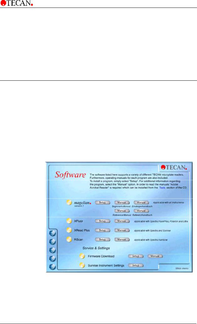
•Insert TECAN Reader PC package CD into the required CD ROM drive.
•The Main menu is displayed. Click the Software button. Click the Setup button for the Firmware Download. The installation program is started.
•A series of dialog boxes will appear, read each one, enter any necessary information and click Next to continue. The files are then installed and the program icon is created.
•When the Installation Complete dialog box appears, click Finish and the Firmware Download program is ready to be used.
February 2002 |
Technical Manual for SUNRISE RC, TW, TS, TC, BC No: T 137 302 Rev No: 1.0 |
3-1 |
3. Firmware and Software Description
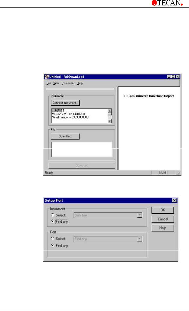
3.1.1Starting the Firmware Download
If an instrument is already connected to one of TECAN's programs, close the program or disconnect the instrument from the program.
To start the Firmware Download Software click the RdrDownload icon on the desktop or click the Start button on the lower taskbar and select Programs – TECAN and select Rdr Download. .
The following dialog box is displayed:
Click Connect Instrument… to establish a link from the instrument to the computer.
The Setup Port dialog box appears:
Select <Find any> and click OK.
3-2 Technical Manual for SUNRISE RC, TW, TS, TC, BC No: T 137 302 Rev No: 1.0 |
February 2002 |

3. Firmware and Software Description
3.1.2Open file
To Download the new Firmware version, click Open file... and select the correct *.upd file from the new window. See picture below. Click Download and the new firmware is Downloaded.
Note:
Do NOT switch off the instrument during the Download process.
When the Download process is finished, the right window displays the Download Report and the message, "Firmware Download successfully finished!".
Select Print Report from the <File> menu to print the Download Report.
February 2002 |
Technical Manual for SUNRISE RC, TW, TS, TC, BC No: T 137 302 Rev No: 1.0 |
3-3 |

3. Firmware and Software Description
3.2 Rdr OLE Server
This program enables the user to define the settings of:
Instrument modes
Filter definition
Measurement modes
3.2.1Installation of Instrument Control Software
For more information about installing the software, see Magellan or XRead Plus manual,
which can be found on the TECAN Reader PC Package CD.
3.3Sunrise Instrument Settings
This program enables the user to define the settings of:
Instrument modes
Filter definition
Measurement modes
3.3.1Installation of SUNRISE Instrument Settings Software
The SUNRISE Instrument Settings software is installed using the following procedure:
•Insert TECAN Reader PC package CD into the required CD ROM drive.
•The Setup dialog box is displayed. Click the Service and Settings button. Click the Setup button for the SUNRISE Instrument Settings. The installation program is started, and the SUNRISE Instrument Settings are installed.
•A series of dialog boxes will appear, read each one, enter any necessary information and click Next to continue.
•The files are then installed and the program icon is created.
•When the Installation Complete dialog box appears, click Finish and the SUNRISE Instrument Settings program is ready to be used.
3-4 Technical Manual for SUNRISE RC, TW, TS, TC, BC No: T 137 302 Rev No: 1.0 |
February 2002 |
3. Firmware and Software Description
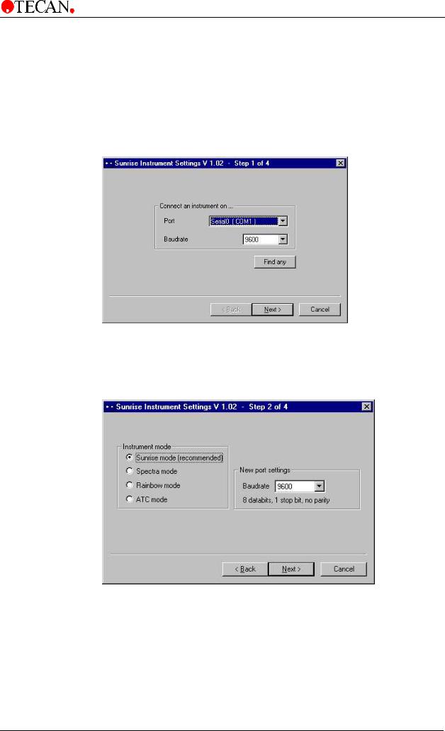
3.3.2Starting the SUNRISE Instrument Settings
In case an instrument is already connected to one of TECAN's programs, close the program or disconnect the instrument from the program.
Click the SUNRISE Instrument Settings icon on the desktop, if present, or click the Start button on the lower taskbar and select Programs – TECAN and select
SUNRISE Instrument Settings. The following dialog box is displayed:
Select the correct communication port and the baudrate. Click Next.
3.3.3Define Instrument Mode
The following dialog box is displayed:
To use the instrument with software designed for former TECAN readers, select the appropriate instrument modes and baudrate. Click Next.
Sunrise mode |
It is recommended to use the SUNRISE mode with 9600 baud. |
Spectra mode |
Simulates a SPECTRA Reader. |
Rainbow mode |
Simulates a Rainbow Reader |
ATC mode |
Simulates an ATC Reader. |
February 2002 |
Technical Manual for SUNRISE RC, TW, TS, TC, BC No: T 137 302 Rev No: 1.0 |
3-5 |
3. Firmware and Software Description
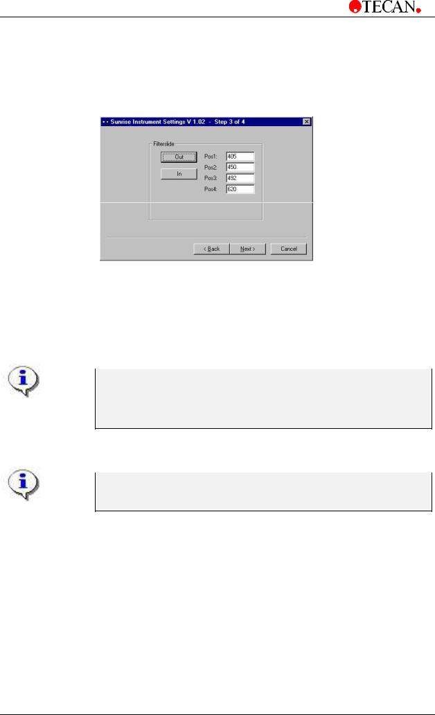
3.3.4Define Filter
The following dialog box is displayed:
Click the Filter slide Out button to move the filter out of the instrument.
To insert a filter slide, open the filter compartment manually and slide the filter into the slot, so that the filter end of the slide is inserted first. (Do not force the filter slide into the instrument beyond the point of resistance).
Click the Filter slide In button and the filter is inserted.
Pos1 - 4 show the filter values for the currently loaded absorbance filters.
The instrument is able to recognize predefined filter slides and the filter values for these slides must not be changed. However, if the filters in the filter slide have been changed (by a service engineer) or if a new undefined customized filter slide is to be used, the filter slides need to be defined.
To define the filter values for a new filter slide, enter the required wavelengths in the text boxes. Click Next.
The wavelength range for the SUNRISE is 340 - 750 nm.
It is not possible to define the tuneable wavelength filter slide from the
Sunset Instrument Settings
3-6 Technical Manual for SUNRISE RC, TW, TS, TC, BC No: T 137 302 Rev No: 1.0 |
February 2002 |
3. Firmware and Software Description
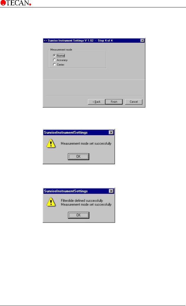
3.3.5Define Measurement Mode
The following dialog box is displayed:
Select the appropriate measurement mode.
Click Finish and the following dialog box is displayed:
The measurement mode has now been set successfully.
If the filter values for the new filter slide has been defined, then the following dialog box is displayed:
February 2002 |
Technical Manual for SUNRISE RC, TW, TS, TC, BC No: T 137 302 Rev No: 1.0 |
3-7 |
3. Firmware and Software Description
3.4 SunSet Software (Service tool kit is necessary!)
This program enables the user to adjust the instrument:
Device configuration
Lamp adjust
Plate calibration
Measurement offsets
User configuration
3.4.1Installation of SUNSET Software
The SunSet Software is installed using the following procedure:
•Double click the setup icon to automatically install the SunSet software or click the Start button on the lower taskbar and select <Run…> from the menu and then browse for the correct setup file.
•A series of dialog boxes will appear, read each one, enter any necessary information and click Next to continue.
•The files are then installed and the program icon is created.
•When the Installation Complete dialog box appears, click Finish and SunSet Software is operational.
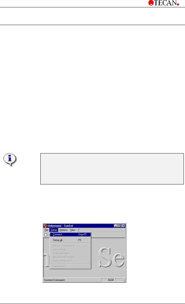
3.4.2Starting the SunSet Software
•Perform the Sunset test with filterslide G or filterslide A.
•Filterslide G ensures that the entire wavelength range is checked (340 - 750 nm)
•It is not possible to do the adjustments
with the Tuneable Wavelength filterslide.
If an instrument is already connected to one of TECAN's programs, close the program or disconnect the instrument from the program.
To start the SunSet Software click the Start button on the lower taskbar and select Programs and then TECAN –from the menus and select SunSet or click the SunSet icon in the directory C:\Programme\Tecan\SunSet.
The following dialog box is displayed:
Select Connect from the Setup menu or press <Strg> and <F5> together to connect the instrument.
3-8 Technical Manual for SUNRISE RC, TW, TS, TC, BC No: T 137 302 Rev No: 1.0 |
February 2002 |
Loading...