

Page 1

SERVICE MANUAL
DVTV5190F
51CM TV DVD COMBO
FEB05 SERVDVTV5190
Page 2

.
CONTENTS
1. Safety precautions……………………………………………………………..……………3
2. TV block diagram……………………………………………………………………..…….4
3. Replacement of memory IC………………………………………………………….……5
4. Service adjustment……………………………………………………………..…………...5
5. ICs functional description…………………………………………………………………8
6. Test point waveform………………………………………………………………………10
7. All ICs voltages……………………………..……………………………………………….10
8. Purity / convergence adjustment………………………………………………………11
9. DVD maintenance…………………………………………………………………………13
10. List of Parts ………………………………………………………………………….…….14
11. Circuit diagram………………………………………………………………………Attached
12. Exploded view…………………………………………………………………Attached
2
Page 3
.
1. SAFETY PRECAUTIONS
1. The design of this product contains special hardware, many
circuits and components especially for safety purposes. For
continued protection, no changes should be made to the
original design unless authorized in writing by the
manufacturer. Replacement parts must be identical to those
used in the original circuits. Service should be performed by
qualified personnel only.
2. Alterations of the design or circuitry of the products should
not be made. Any design alterations or additions will void the
manufacturer’s warranty and will further relieve the
manufacturer of responsibility for personal injury or property
damage resulting therefrom.
3. Many electrical and mechanical parts in the products have
special safety-related characteristics. These characteristics
are often not evident from visual inspection nor can the
protection afforded by them necessarily be obtained by using
replacement components rated for higher voltage, wattage,
etc. Replacement parts which have these special safety
characteristics are identified in the parts list of Service
manual. Electrical components having such features are
identified by shading on the schematics and by ( ! ) on
the parts list in Service manual. The use of a substitute
replacement which does not have the same safety
characteristics as the recommended replacement part
shown in the parts list of Service manual may cause shock,
fire, or other hazards
4. Don’t short between the LIVE side ground and
ISOLATED (NEUTRAL) side ground or EARTH side
ground when repairing. Some model’s power circuit is
partly different in the GND. The difference of the GND is
shown by the LIVE: ( ) side GND, ISOLATED
(NEUTRAL): ( ) side GND and EARTH: ( ) side GND.
Don’t short between the LIVE side GND and ISOLATED
(NEUTRAL) side GND or EARTH side GND and never
measure with a measuring apparatus (oscilloscope etc.) the
LIVE side GND and ISOLATED (NEUTRAL) side GND or
EARTH side GND at the same time. If above note will not be
kept, a fuse or any parts will be broken.
5. If any repair has been made to the chassis, it is
recommended that the B1 setting should be checked or
adjusted (See ADJUSTMENT OF B1 POWER SUPPLY).
6. The high voltage applied to the picture tube must conform to
that specified in Service manual. Excessive high voltage can
cause an increase in X-Ray emission, arcing and possible
component damage, therefore operation under excessive
high voltage conditions should be kept to a minimum, or
should be prevented. If severe arcing occurs, remove the AC
power immediately and determine the cause by visual
inspection (incorrect installation, cracked or melted high
voltage harness, poor soldering, etc.). To maintain the proper
minimum level of soft X-Ray emission, components in the
high voltage circuitry including the picture tube must be the
exact replacements or alternatives approved by the
manufacturer of the complete product.
7. Do not check high voltage by drawing an arc. Use a high
voltage meter or a high voltage probe with a VTVM.
Discharge the picture tube before attempting meter
connection, by connecting a clip lead to the ground frame
and connecting the other end of the lead through a 10kΩ 2W
resistor to the anode button.
8. When service is required, observe the original lead dress.
Extra precaution should be given to assure correct lead
dress in the high voltage circuit area. Where a short circuit
has occurred, those components that indicate evidence of
overheating should be replaced. Always use the
manufacturer’s replacement components.
9. Isolation Check
(Safety for Electrical Shock Hazard)
After re-assembling the product, always perform an isolation
check on the exposed metal parts of the cabinet (antenna
terminals, video/audio input and output terminals, Control
knobs, metal cabinet, screw heads, earphone jack, control
shafts, etc.) to be sure the product is safe to operate without
danger of electrical shock.
10. The surface of the TV screen is coated with a thin film which
can easily be damaged. Be very careful with it when handle
the TV. Should the TV screen become soiled, wipe it with a
soft dry cloth. Never rub it forcefully. Never use any cleaner
or detergent on it.
(1) Dielectric Strength Test
The isolation between the AC primary circuit and all metal
parts exposed to the user, particularly any exposed metal
part having a return path to the chassis should withstand a
voltage of 3000V AC (r.m.s.) for a period of one second.
(…Withstand a voltage of 1100V AC (r.m.s.) to an appliance
rated up to 120V, and 3000V AC (r.m.s.) to an appliance
rated 200V or more, for a period of one second.)
This method of test requires test equipment not generally
found in the service trade.
(2) Leakage Current Check
Plug the AC line cord directly into the AC outlet (do not use
line isolation transformers during this check). Using a
“Leakage Current Tester”, measure the leakage current from
each exposed metal part of the cabinet, particularly any
exposed metal part having a return path to the chassis, to a
known good earth ground (water pipe, etc.). Any leakage
current must not exceed 0.5mA AC (r.m.s.).
However, in tropical area, this must not exceed 0.2mA AC
(r.m.s.).
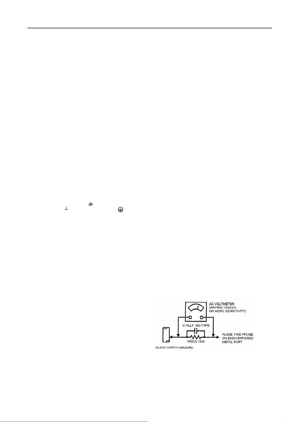
●Alternate Check Method
Plug the AC line cord directly into the AC outlet ( do not use
a line isolation transformer during this check.). Use an AC
voltmeter having 1000 ohms per volt or more sensitivity in
the following manner. Connect a 1500Ω 10W resistor
paralleled by a 0.15µF AC-type capacitor between an
exposed metal part and a known good earth ground (water
pipe, etc.). Measure the AC voltage across the resistor with
the AC voltmeter. Move the resistor connection to each
exposed metal part, particularly any exposed metal part
having a return path to the chassis, and measure the AC
voltage across the resistor. Now, reverse the plug in the AC
outlet and repeat each measurement. Any voltage measured
must not exceed 0.75V AC (r.m.s.). This corresponds to
0.5mA AC (r.m.s.).
However, in tropical area, this must not exceed 0.3V AC
(r.m.s.).
This corresponds to 0.2mA AC (r.m.s.)
3
Page 4
.
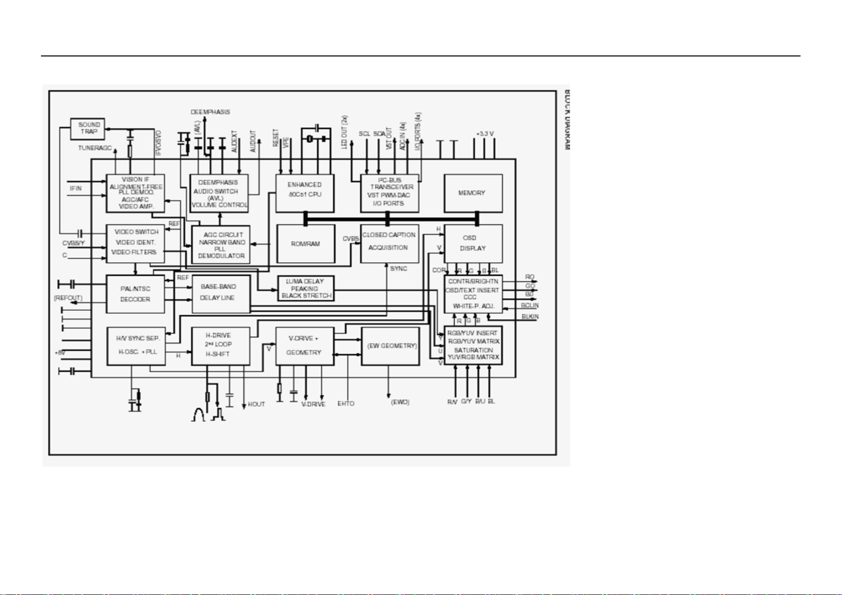
2. Block diagram TDA9370PS/N2 series with mono intercarrier sound demodulator
4
Page 5

3. REPLACEMENT OF MEMORY IC
1. MEMORY IC.
This TV uses memory IC. In the memory IC are memorized data for correctly operating the video and deflection
circuits.
2. PROCEDURE FOR REPLACING MEMORY IC
(1) Power off
Switch the power off and unplug the power cord from AC outlet.
(2) Replace IC
Be sure to use memory IC written with the initial data values.
(3) Power On
Plug the power cord into the AC outlet and switch the power on.
(4) Check and set SYSTEM default value:
1) Press “MUTE” Æ “CALL” Æ “-\--“ Æ “CALL” Æ “MUTE” buttons in sequence to enter into factory
status.
2) If the memory IC haven’t been written with the initial data, press [Program+] / [Program-] to select item
INIT and press [VOLUME+] / [VOLUME-] to start initialize memory IC.
3) Check the setting value of the SYSTEM default value of Table below. If the value is different, select
items by [Program+] / [Program-] keys and set value by [VOLUME+] / [VOLUME-] keys.
4) Press “EXIT” button to return to the normal screen.
4. SERVICE ADJUSTMENT
Specific operation: use remote controller
Press “MUTE” Æ “CALL” Æ “-\--“ Æ “CALL” Æ “MUTE” buttons in sequence to enter into factory mode.
Press [Program+] / [Program-] to select items and press [VOLUME+] / [VOLUME-] key, to make data adjustment
of corresponding factory menus.
Press “EXIT” key to exit factory mode.
Focus adjustment
1. Receive a crosshatch signal.
2. While watching the screen, adjust the FOCUS VR on the FBT to make the vertical and horizontal lines as
fine and sharp as possible.
Geometrical adjustment
Receive PAL standard complete pattern signal.
Adjustment steps:
a) Adjust VSL, to the centre horizontal line just appears from half bottom shadow.
b) Adjust VAM, to get 92% of vertical picture contents would be displayed on CRT.
c) Adjust VSH, the centre horizontal line corresponds to CRT vertical centre.
d) Adjust SCL, to the linearity of P card field is in proper condition.
e) Adjust
Receive NTSC signal and repeat above adjustment.
AGC Adjustment
Receive 60dBµ (1mV) VH colour bar pattern signal.
Select TOP item.
Adjust value, to noise reduce gradually and just disappeared point.
CRT cut off and white balance adjustment
a) CRT cut off adjustment
b) White balance adjustment
HSH, to get the picture horizontal centre correspond to CRT horizontal centre.
1. Select item VG2B, then adjust value to 32.
2. PRESS “0” key, when the screen shows”VG2” adjust the SCREEN control on Fly back transformer to
make the screen show alternating flashing characters of “INSIDE HIGH INSIDE LOW”.
1. Receive a Black and White pattern.
2. Adjust WRP, WRG, WRB items to get colour temperature 9300K ±3 JND.
5
Page 6
Adjustable Items
Direct access key Items Description Preset Remark
“1” 5/6HSH Horizontal shift ON A
“2” 5/6VSL Vertical slop 32 A
5/6VAM Vertical amplitude 23 A
5/6SCL S-correction 17 A
5/6VSH Vertical shift 27 A
5/6VOF OSD Vertical offset 37 A
HOF* OSD Horizontal offset 42 A
“3” RED Black level offset R 32 A
GRN Black level offset G 32 A
WPR White point R 30 A
WPG White point G 26 A
WPB White point B 38 A
“4” TOP AGC Take-over point 20 A
VOL Volume 42
9860 Sub-volume of TDA9860/59 18
HDOL Cathode drive level 59
AGC IF AGC speed 1
VG2B VG2 Brightness 42
IFFS 2
“5” Picture preset 1
0CON Listen: Contrast 0 A
0BRI Listen: Brightness 0 A
0COL Listen: Colour 50 A
0SHP Listen: Sharpness 50 A
1CON Soft: Contrast 45 A
1BRI Soft: Brightness 45 A
1COL Soft: Colour 50 A
1SHP Soft: Sharpness 50 A
“6” Picture preset 2
2CON Standard: Contrast 75 A
2BRI Standard: Brightness 50 A
2COL Standard: Colour 50 A
2SHP Standard: Sharpness 60 A
3CON Dynamic: Contrast 85 A
3BRI Dynamic: Brightness 60 A
3COL Dynamic: Colour 60 A
3SHP Dynamic: Sharpness 80 A
NOTE: THE ITEMS WITH REMARK “A” IS ADJUSTABLE DATA.
Optional data
1. OP1
Bit Function Description Preset Remark
Bit 0 VG2_MODE 1= 0 EA
Bit 1 YPRPB 1=Enable 1 EA
Bit 2 SUPERWOOFER Translucence OSD manual 1=Enable 0 EA
Bit 3 WOOFER_VOL 1=Enable (Can only be selected either RGB and DVD) 0 EA
Bit 4 AV2 1=Enable 1 EA
Bit 5 SVHS 1=Enable 0 EA
Bit 6 DVD 1=Enable 0 EA
Bit 7 RGB 1=Enable 1 EA
6
Page 7
2. OP2
Bit Function Description Preset Remark
Bit 7 FSL 1=21dBµV 0=26dBµV 0 EA
Bit 6 SOY 1=Enable 1 EA
Bit 5 ARABIC_SET 1=Enable 0 EA
Bit 4 FARSI_SET 1=Enable 0 EA
Bit 3 CYRILLIC_SET 0 EA
Bit 2 EUROUP_SET 1=Enable 1 EA
Bit 1 AUTO_SOUND 1 EA
Bit 0 AVL 1=Enable 1 EA
3. OP3
Bit Function Description Preset Remark
Bit 7 RUSSIA 1=Enable 0 EA
Bit 6 ITALY 1=Enable 0 EA
Bit 5 GERMANY 1=Enable 0 EA
Bit 4 FRANCE 1=Enable 0 EA
Bit 3 RUTKISH 1=Enable 0 EA
Bit 2 ARABIC 1=Enable 0 EA
Bit 1 FARSI 1=Enable 0 EA
Bit 0 ENGLISH 1=Enable 1 EA
4. OP4
Bit Function Description Preset Remark
Bit 6 HALFTONE 1=Enable 1 EA
Bit 5 IDENT_SENSITIVE 1 EA
Bit 4 HCO 1=Enable 0 EA
Bit 3 LOGO 1 EA
Bit 2 TILT 0 EA
Bit 1 SPANISH 1 EA
Bit 0 ROMANIA 0 EA
5. OP5
Bit Function Description Preset Remark
Bit 7 STORE_AV 1= Enable 1 EA
Bit 6 OSO 1= Enable 0 EA
Bit 5 SOFR_CHANGE 1=Enable 0 EA
Bit 4 FADE 1=Enable 0 EA
Bit 3 SOUND_M 1= Enable 0 EA
Bit 2 SOUND_I 1= Enable 0 EA
Bit 1 SOUND_BG 1=Enable With DVD select 1 1 EA
Bit 0 SOUND_DK 1=Enable 0 EA
6. OP6
Bit Function Description Preset Remark
Bit 7 RESERVE 1=Enable 0 EA
Bit 6 POR_WHEN_BLUE 1=Enable 1 EA
Bit 5 MENU_MIDLINE 1=Enable 1 EA
Bit 4 MENU_BLUE 1=Enable 1 EA
Bit 3 CHILDLOCK 1=Enable 1 EA
Bit 2 16_9 1=Enable 0 EA
Bit 1 BLUE_SCREEN 1=Enable 1 EA
Bit 0 LOGO_LISTEN 1 EA
7
Page 8
7. OP7
Bit Function Description Preset Remark
Bit 7 FMWS 1=Enable 1 EA
Bit 6 HOTEL 1=Enable 0 EA
Bit 5 PROG_ID 1=Enable 0 EA
Bit 4 LED 1=Enable 0 EA
Bit 3 TWIST 1=Enable 0 EA
Bit 2 BYELORUSSIAN 1=Enable 0 EA
Bit 1 UKRANIAN 1=Enable 0 EA
Bit 0 AV1 1=Enable 1 EA
8. OP8
Bit Function Description Preset Remark
Bit 6 DIRECT_SWITCH_ON 1=Enable 0 EA
Bit 5 INNER_DVD 1=Enable 1 EA
Bit 4 PROG_FREQ 1=Enable 0 EA
Bit 3 FAST_BAR 1=Enable 1 EA
Bit 2 AUSTRALIA 1=Enable 0 EA
Bit 1 FREQ 1=Enable 1 EA
Bit 0 9860 1=Enable 0 EA
Note:Don’t adjust any OPTION items, please inform the engineer about any change.
5. ICs functional description
1. N201 UOC TDA9370
SYMBOL PIN DESCRIPTION
STAND BY output. 1 In STAND BY mode, low level (Power OFF).
For Power ON this pin will be high.
SCL 2 I2C-bus clock line
SDA 3 I2C-bus data line
TUNING 4 tuning Voltage (Vt) PWM output
KEY 5 Control keys input
SYSTEM 6 TV system control
VOL 7 Sound Volume control PWM output
MUTE 8 Sound mute output
VSSC/P 9 Digit ground for µ-controller core and periphery
CTL 10 DVD power control
STANDBY 11 STANDBY control
VSSA 12 Analog ground of digital ground of TV-processor
SECPLL 13 Internally connected
VP2 14 2nd supply voltage TV-processor(+8V)
DECDIG 15 decoupling digital supply of TV-processor
PH2LF 16 Phase-2 filter
PH1LF 17 Phase-1 filter
GND3 18 Ground 3 for TV-processor
DECBG 19 Band gap decoupling
AVL/EWD 20 Automatic volume levelling
VDRB 21 Vertical drive B output
VDRA 22 Vertical drive A output
IFIN1 23 IF input 1
IFIN2 24 IF input 2
8
Page 9
IREF 25 Reference current input
VSC 26 Vertical sawtooth capacitor
TUNER AGC 27 Tuner AGC output
AUDEEM/SIFIN1 *1 28 Audio deemphasize or SIF input
DECSDEM/SIFIN2 29 Decoupling sound demodulator
GND2 30 Ground 2 for TV processor
SNDPLL/SIFAGC *1 31 Narrow band PLL filter
AVL 32 Automatic Volume Levelling
HOUT 33 Horizontal output
FBISO 34 Flyback input/sandcastle output
AUDEXT 35 External audio output
EHTO 36 EHT/over voltage protection input
PLL IF 37 IF-PLL loop filter
IFVO/SVO 38 IF video output / selected CVBS output
VP1 39 supply voltage TV processor
CVBS INT 40 internal CVBS input
GND1 41 ground for TV processor
CVBS/Y 42 CVBS/SVHS(Y) input
CHROMA 43 SVHS (C) input
AUDOUT 44 Audio output
INSSW2 45 YUV insertion input
R2/VIN 46 R input / V (R-Y) input / PR input
G2/YIN 47 G input / Y input
B2/UIN 48 B input / U (B-Y) input / PB input
BCLIN 49 Beam current limiter input
BLKIN 50 Black current input
RO 51 Red output
GO 52 Green output
BO 53 Blue output
VDDA 54 Analog supply of Closed Caption decoder and digital supply of TV-processor (3.3 V)
VPE 55 Ground
VDDC 56 Digital supply to core (3.3 V)
OSCGND 57 Oscillator ground supply
XTALIN 58 Crystal oscillator input
XTALOUT 59 Crystal oscillator output
RESET 60 Ground
VDDP 61 Digital supply to periphery (+3.3 V)
P1.0/INT1 62 AV1 / AV2 mode Output.
P1.1/T0 63 AV /S-VHS mode Output.
P1.2/INT0 64 Remote control signal input.
Note
Pin TV SVHS AV1 AV2
62 1 0 0 1
63 1 1 0 0
2. N902 24C08/PCF8598
PIN Function
1 GND
2 GND
3 Upper resistance
4 GND
5 SDA data wire
6 SCL clock wire
7 GND
8 +5V Power
3. N601: Sound power amplify (AN7522N)
Symbol PIN Function Symbol PIN Function
Vcc 1 Power supply GND 7 ground
Out 1 (+) 2 Ch 1 output (+) In 2 8 Ch 2 input
GND(out 1) 3 Ch 1Ground VOL 9 Volume Control
Out 1 (-) 4 Ch 1 output (-) Out 2 (-) 10 Ch 2 output (-)
Standby 5 Mute input GND(out 2) 11 Ch 2 Ground
9
Page 10
In 1 6 Ch 1 input Out 2 (+) 12 Ch 2 output (+)
4. N301: Vertical output (TDA8357A)
Symbol PIN Function Symbol PIN Function
INV IN 1 Input PUMP UP 6 Pump up power
INV IN 2 Input V OUT 7 Vertical output
Vcc 3 Pump up power V PRO 8 Vertical protection
V OUT 4 Vertical output V FEEDBACK 9 Vertical feedback
GND 5 Ground
5. U101:Tuner
PIN Function PIN Function
1 AGC 7 +5V
2 vacant 8 vacant
3 Gnd 9 Vt 33V
4 SCL 10 Gnd
5 SDA 11 IF Out
6 +5V
6. Test point Waveforms
2.6Vpp
H
TDA9370 PIN38
95Vpp
H
CRT KG CRT KR
1Vpp
V
TDA9370 PIN21 TDA9370 PIN22 TDA9370 PIN59
1.2Vpp
H
TDA9370 PIN40
95Vpp
H H
0.8Vpp
V
CRT KB
TDA9370PIN53
95Vpp
1.3Vpp
3.8Vpp
H
2.5Vpp
H H
TDA9370PIN52
0.9Vpp
H
TDA9370 PIN33
2.5Vpp
TDA9370 PIN51
TDA9370 PIN34
5Vpp
H
7. IC voltages
10
Page 11

TDA9370
PIN 1 2 3 4 5 6 7 8 9 10 11 12 13 14 15 16
V 0 3.8 3.6 3.3 3.5 4.4 5.1 1.8 0 0.18 0.17 0 2.3 8 5 3
PIN 17 18 19 20 21 22 23 24 25 26 27 28 29 30 31 32
V 4 0 4 0.5 0.7 0.8 1.9 1.9 3.9 3.8 1.6 3.2 2.3 0 2.3 0.2
PIN 33 34 35 36 37 38 39 40 41 42 43 44 45 46 47 48
V 0.5 0.3 0 1.7 2.4 3.4 8 3.9 0 3.3 0 3.6 1.4 2.5 2.5 2.5
PIN 49 50 51 52 53 54 55 56 57 58 59 60 61 62 63 64
V 1.9 5.0 2.4 2.4 2.4 3.1 0 3.2 0 1.8 1.7 0 3.2 5.1 3.3 5
TDA8357
PIN 1 2 3 4 5 6 7 8 9
V 0.8 0.7 16 6.9 0 43 7.2 0.3 7.2
AN 7522N
PIN 1 2 3 4 5 6 7 8 9 10 11 12
V 10 4.4 0 4.4 2.75 1.4 0 1.4 0.35 4.4 0 4.4
24C08/PCF8598
PIN 1 2 3 4 5 6 7 8
V 0 0 5.1 0 3.2 0 0 5.1
8. PURITY / CONVERGENCE ADJUSTMENT
11
Page 12

6
PURITY ADJUSTMENT
1. Demagnetize CRT with the demagnetizer.
2. Loosen the retainer screw of the deflection yoke.
3. Remove the wedges.
4. Input a green raster signal from the signal generator,
and turn the screen to green raster.
5. Move the deflection yoke backward.
6. Bring the long lug of the purity magnets on the short
lug and position them horizontally. (Fig2)
7. Adjust the gap between two lugs so that the GREEN
RASTER will come into the centre of the screen.
(Fig. 3)
8. Move the deflection yoke forward, and fix the position
of the deflection yoke so that the whole screen will
become green.
9. Insert the wedge to the top side of the deflection yoke
so that it will not move.
10. Input a crosshatch signal.
11. Verify that the screen is horizontal.
12.
Input red and blue raster signals, and make sure that
purity is properly adjusted.
Long lug
Short lug
WEDGE
DEFLECTION YOKE
P
CRT
P: PURITY MAGNET
4: 4-POLES
6: 6-POLES (convergence magnets)
4
P/C MAGNETS
(convergence magnets)
Fig. 1
PURITY MAGNETS
Bring the long lug over the short lug and
position them horizontally.
Fig. 2
(FRONT VIEW)
GREEN RASTER
CENTER
Fig. 3
12
Page 13
STATIC CONVERGENCE ADJUSTMENT
1. Input a crosshatch signal.
2. Using 4-pole convergence magnets overlap the red
and blue lines in the center of the screen (Fig. 1) and
turn them to magenta (red/blue).
3. Using 6-pole convergence magnets overlap the
magenta (red/blue) and green lines in the center of the
screen and turn them to white.
4. Repeat 2 and 3 above, and make the best
convergence.
DYNAMIC CONVERGENCE ADJUSTMENT
1. Move the deflection yoke up and down and overlap
lines in the periphery. (Fig. 2)
2. Move the deflection yoke left to right and overlap the
lines in the periphery. (Fig. 3)
3. Repeat 1 and 2 above, and make the best
convergence.
After adjustment, fix the wedge at the original position.
Fasten the retainer screw of the deflection yoke.
Fix the 6 magnets with glue.
(FRONT VIEW)
Fig. 1
(FRONT VIEW)
RED GREEN BLUE
BLUE
GREEN GREEN
RED BLUE
BLUE GREEN RED
RED
Fig.2
(FRONT VIEW)
RED GREEN BLUE BLUE GREEN RED
RED
GREEN
BLUE
BLUE
GREEN
RED
Fig. 3
13
Page 14

9. DVD Part: Introduction of MTK1379 maintenance
1. Under normal power supply conditions, the maintenance plan for MT1379 mono-chip is: first the reset
circuit resets the MT1379, after the crystal oscillator circuit gave the clock signal to MT1379, MT1379 will
start the initialization check for Flash、E
start initialization check for 7Audio DAC, MT1336 and motor Driver.
2. If the all the a.m. parts are good, then MT1379 will send signal to motor Driver to drive the servo system,
pick up then to generate DVD light for collection, tracing the main shaft to check if there is any disc, and
confirm if it is CD format or DVD format disc. If the disc is in DVD format, the system will read the data
from the disc directly; if it is in CD format MT1336 will drive the CD laser to send out CD light and read the
data, the data then will be amplified through MT1336 and sent to MT1379 for data processing, released by
MPEG and resolved into video data and audio data, then they will be returned to analog signals through
VIDEO DAC、AUDIO DAC.
Decoder section
3. There is power supply, clock and reset, but the system does not work.
1) Check if all the address wires required for FLASH are exist, and if they are in normal status,
especially check if the A0~A15 of FLASH have normal signals, if there aren’t, then inspect MT1379
to see if there is faulty soldering. If there are normal signals at A0~A15, check if the address data
signal of MT1379 and SDRAM is normal. If it is normal, then check the signal at A16~A19 of
MT1379; if there are also signals, then check the 8 video data wires; it there is no signal, then
check the corresponding pins of MT1397 to see if there is any short circuit, break or faulty
soldering.
2) If all the a.m. conditions are good, but there is still no video signal output, then the filter circuit after
MT1379 shall be checked.
4. System in normal operation, but the audio has no sound.
1) Check if all the signals of DATA, MCLK, BCLK, LRCK and reset required by the Audio DAC are
exist, if there is signal missing, then check the signal line between MT1379 and Audio DAC. If the
line is connected properly, but there is no signal, then check if there is any welding problem at the
corresponding pins of MT1379. If it is still OK, it is probably the problem on MT1379 itself.
2) All the required signals are exist, while there is no audio output. Then you need to check the lower
passing amplifying circuit and the MUTE circuit at the back of Audio DAC. Also check if there is
any power supply to the Audio DAC.
3) Check if the power supply voltage required for playing is at normal level.
Servo Section
5. After the LOGO of the machine shows normally, there is no OSD display. This problem mainly is caused
by the abnormality between servo and MPEG, possible problems may be:
1) T1336 and its surrounding circuits have problems.
2) Servo part of MT1379 has problems.
6. OSD display is normal,while there is no action of servo part(feeding motor does not work, main shaft does
no turn, possible fault status are:
1) The corresponding signals giving by MT1379 to DMSO、FMSO are missing, the reason may be the
problem of MT1379 or the communication between MT1379 and motor Driver.
2) Not output from Motor Driver, the reason may be the problem on motor Driver or its corresponding
circuit.
7. Servo part in good status, while there is no pick up action(no light, no focus)
2
PROM、SDRAM, after everything is checked to be normal, it will
1) No light, check the power supply(power supply for pick up), or the light producing driving circuit to see
if they are in normal status.
2) No focus, check MT1379 to see if there is signal output from FOSO、TRSO.
Secondly, check motor driver to see if there is F+、F-、T+、T-signal output.
Thirdly, check the external corresponding circuit of the motor driver to see if there is any problem.
8. All the servo part has action, while it cannot read out the disc
1) Check MT1336 if there is RF net picture output, if there isn’t, then it must be the problem of MT1336
and external surrounding circuits, it there is output, then it might the problem of MT1369 and its
surrounding circuits.
14
Page 15

2) There is RF signal,but not in normal status,then check MT1336 and surrounding circuits.
3 )Everything is normal, but the disc cannot be read out, check MT1369 and its surrounding circuit
10. List of Parts
PART
LOCATION DESCRIPTION
FRONT CABINET ASS’Y BCJ7008-----Q 90806302 1
LENS MTAA7011AA--Q 90204520 1
SCREW SJ2824-87 ST3X10F 90600011 1
KEYS MTAA7012AA--Q 90204553 1
SCREW SJ2824-87 ST3X10F 90600011 3
SCREW SJ2838-87 ST3x12F 90600200 2
SWITCH BUTTON MTAA7013AA--Q
SPRING MTBH7004BC--Q 90100663 1
SPEAKER YDT0407-9AU-8W-8Ω
SPEAKER WIRE 90401453 2
SCREW SJ2824-87 ST3X8F 90600012 8
SCREW SJ2824-87 ST4X12F 90600015 2
WIRE ASS’Y D2006-12P-D2512-10P-TJC3-2P-350 90401676 1
FRONT AV CONNECTOR ASS’Y 90401336 1
DVD STAND MTAC7014AA--Q 90204556 1
SCREW SJ2824-87 ST3X12F 90600034 4
DVD ASS’Y DC005B 94006927 1
BACK CABINET MTFC7011AJ--Q 90204557 1
SCREW SJ2825-87 ST3X10F 90600037 1
AV LABEL 69.6X71.4
HIGH VOLTAGE SPACER TEM101 90200008 1
DVD DOOR MTAH7008AA--Q 90204558 1
POWER CORD CLIP MTAH7005AA--Q 90205627 1
SCREW SJ2824-87 SJ4X16F 90600023 8
SCREW SJ2824-87 SJ4X16F 90600023 2
TOP FOAM STAND MTEE7013AB--Q
BOTTOM FOAM STAND MTEE7014AB--Q
PLASTIC BRACKET MTFC1014AJ--Q 90806490 1
SCREW SJ2825-87 ST3X10F 90600037 6
UL POWER CORD JPRVVZ202XDFQ 90402120 1
040 PLASTIC CLIP MTAJ1001AG--Q 90200038 1
CRT ASS’Y 94005582 1
21" CRT A51LXR195X91JD 94004133 1
GROUNDING WIRE TJC1-1Y/2 90401291 1
DEGUASSING COIL HXC-54D 94500818 1
NUT M6 90600003 1
PARKAGING ASS’Y 90804858 1
RATING LABEL MTFB5364CA--Q 90205788 1
CARTON BOX 90505178 1
BATTERY 5# 94000105 2
DVD SHIELD(UP)
DVDSHIELD(DOWN)
90100709 1
90100710 1
15
NUMBER QTY
90204554
94008903
90204538
90503695
90503696
1
2
1
1
1
Page 16

PLASTIC BAG FOR USER MANUAL
REMOTE CONTROL
90204759
94009887
1
1
PLASTIC BAG FOR 21” COMPLETE SET 90500102 1
PLASTIC BAG FOR POWER CORD 90500018 1
USER MANUAL 90504553 1
TELESCOPIC MAST 94501185 1
MAIN BAORD ASS’Y 94008724 1
N301B HEAT SINK HEAT SINK 90100450 1
N301C IC TDA8357J 94401409 1
N301D SCREW ST3X8F SJ2831-87 90600097 1
V401B SCREW ST3X8F SJ2831-87 90600097 1
V401A HEAT SINK QHS-30184A 90100017 1
V401 TRANSISTOR 2SD2499 94401401 1
N801A HEAT SINK QHS-30184A 90100661 1
N801C IC KA5Q0765RTH-YDTU 94401392 1
N801D SCREW ST3X8F SJ2831-87 90600097 1
N802C IC L7809CS 94400808 1
N802B SCREW ST3X8F SJ2831-87 90600097 1
N802A HEAT SINK QHS-30184A 90100017 1
N601B IC AN7522N 94401684 1
N601A HEAT SINK QHS-30184A 90100665 1
N601C SCREW ST3X8F SJ2831-87 90600097 2
N804B IC KA278R05 94401923 1
N804A HEAT SINK MTBH4070BC--Q 90100443 1
N804C SCREW ST3X8F SJ2831-87 90600097 2
VD806 IC FFPF10U20STU 94401512 1
R625 CARBON FILM RESISTOR RT13-1/6W-1K-J------T 94100023 1
R110 METAL OXIDE RESISTOR RY16S-1W-33-J-05-E-A 94102578 1
R407 METAL OXIDE RESISTOR RY16S-1W-3.9K-J-12.5-E-A 94102667 1
R307 METAL OXIDE RESISTOR RY17S-2W-390-J-05-E-A 94100097 1
R414 METAL OXIDE RESISTOR RY17S-2W-1K-J-05-E-A 94102457 1
R413 METAL OXIDE RESISTOR RY17S-2W-7.5K-J-05-E-A 94100098 1
R810 METAL OXIDE RESISTOR RY17S-2W-18K-J-17.5-L-A 94102580 1
R802 METAL OXIDE RESISTOR RY17S-2W-33K-J-05-E-A 94100101 1
R801 METAL OXIDE RESISTOR RY17S-2W-33K-J-05-E-A 94100101 1
R501H
CARBON FILM RESISTOR RT13-1/6W-47-J------T 94100066 1
C501 CERAMIC CAPACITOR CC1-B-500V-470PF-K-F05 94201264 1
C502 CERAMIC CAPACITOR CC1-B-500V-470PF-K-F05 94201264 1
R502
CARBON FILM RESISTOR RT13-1/6W-47-J------T 94100066 1
R825 METAL OXIDE RESISTOR RY17S-2W-47K-J-05-E-A 94102581 1
R818 METAL OXIDE RESISTOR RY15S-1/2W-1.5K-J------T 94100085 1
R503
R505
R506
R820 FUSE RESISTOR
CARBON FILM RESISTOR RT13-1/6W-47-J------T 94100066 1
FUSE RESISTOR RF10-2W-2.4Ω-J-A 94100704 1
FUSE RESISTOR
RF10-2W-68-J-05-E-A 94100128
RF10-2W-68Ω-J-05-C 94100128
1
R821 FUSE RESISTOR RF10-2W-1-J-05-E-A 94100125 1
R824 FUSE RESISTOR RF10-1/2W-1-J-05-E-A 94102583 1
R415 FUSE RESISTOR RF10-1/2W-1-J-05-E-A 94102583 1
R302 FUSE RESISTOR RF10-1/2W-10-J-05-E-A 94102668 1
R409 FUSE RESISTOR RF10-1/2W-0.22-J-05-E-A 94102584 1
R306 FUSE RESISTOR RF10-2W-0.68-J-05-E-A 94102586 1
R815 FUSE RESISTOR RF10-2W-0.18-J-15-L-A 94102669 1
R416 FUSE RESISTOR RF10-1/2W-68-J-12-L-A 94102591 1
DV801 TVR14561 94400806 1
P801 THERMISTOR MZ73-14RM270V 94400046 1
16
Page 17

RP801 THERMISTOR MF72-2-5Ω±N 94400047 1
C248 CERAMIC CAPACITOR CS1-F-63V-0.1µF-Z-F05 94201617 1
C419 CERAMIC CAPACITOR CT1-B-2kV-681pF-K-07-A 94201373 1
C410 CERAMIC CAPACITOR CT1-B-2kV-681pF-K-07-A 94201373 1
C807 CERAMIC CAPACITOR CT1-B-2kV-561pF-K-07-A 94200067 1
C810 CERAMIC CAPACITOR CT1-B-500V-560pF-K-F05 94201449 1
C823 CERAMIC CAPACITOR CT81-400VAC-18B-2E4-332-M-10-C-A 94202412 1
C805 CAPACITOR CT1-B-1kV-1000pF-K-07-A 94201071 1
C849 CAPACITOR CL21X-63V-224-J------F 94201463 1
C216 CAPACITOR CL21X-63V-224-J------F 94201463 1
C414 CAPACITOR CL21X-400V-104-J-07-A-A 94200098 1
C227 CAPACITOR CBB13-50V-104-J-07-A-A 94200099 1
C416 CAPACITOR CBB21-400V-364-J-20-G-A 94200101 1
C409 CAPACITOR
CBB81-1.6KV-752-J-20-A-A 94200104
1
C802A CAPACITOR MKT61-275V-104-M-15-G-A 94200105 1
C222 ELECT. CAPACITOR CD110X-50V-1µF-M-F05 94200043 1
C236 ELECT. CAPACITOR CD110X-16V-22µF-M-F05 94201043 1
C846 ELECT. CAPACITOR CD110X-25V-1000µF-M-05-A 94201011 1
C811 ELECT. CAPACITOR CD110X-25V-2200µF-M-05-A 94201319 1
C610 ELECT. CAPACITOR CD110X-25V-1000µF-M-05-A 94201011 1
C304 ELECT. CAPACITOR CD263-100V-33uF-M-05-A 94202297 1
C418 ELECT. CAPACITOR CD263-100V-33uF-M-05-A 94202297 1
C808 ELECT. CAPACITOR CD263-160V-100µF-M-07-A 94200736 1
C411 ELECT. CAPACITOR CD288H-250V-22uF±20%-05-G-A 94201604 1
C801 ELECT. CAPACITOR CD293-400V-150µF-M-10-A 94201341 1
C852 ELECT. CAPACITOR CD110X-16V-1000µF-M-F05 94200802 1
N201 IC TDA9370PS/N2/A 94401831 1
N202 IC M24C08(BR24C08) 94400636 1
N202 IC PC817C 94400036 1
N703 IC TC4052BP 94400138 1
N805 IC KA78R12 94401924 1
N702 IC HEF4053 94400503 1
X201 CRYTAL JA12D-12MHZ-20PF 94600198 1
Z201 CERAMIC TRAP FILTER
XT5.5B 94600015 1
TU101 TUNER ENV56DB4G3 94003734 1
SF101 SAW FILTER
D1510C
94600292 1
F801 FUSE TSG-3.15A-250V 94000137 1
F801A FUSE CLIP FC503 90100021 1
F801B FUSE CLIP FC503 90100021 1
L401 LINEARITY COIL LX034 94501053 1
L801 LINE FILTER LCL-207 94500686 1
T444 FLYBACK TRANSFORMER
BSC25-0283G 94501054
1
T801 SWITCHING MODE TRANSFORMERBCK-07-DE7 94501146 1
T401 HORIZONTAL TRANSFORMER AA26-50001B 94500034 1
LW INDUCTOR
V999 CRT SOCKET
TK115 94401063
GZS10-2-BD 94300007
1
1
CN801 CONNECTOR SOCKET TJC1-2A 94300110 1
CN802 CONNECTOR SOCKET TJC2-2A 94300063 1
CN601 CONNECTOR SOCKET TJC3-2A 94300092 1
CN602 CONNECTOR SOCKET TJC3-2A 94300092 1
CN502 CONNECTOR SOCKET TJC3-3A 94300111 1
CN200 CONNECTOR SOCKET TJC3-3A 94300012 1
CN211 CONNECTOR SOCKET TJC3-3A 94300012 1
CN210 CONNECTOR SOCKET TJC3-5A 94300104 1
CN503 CONNECTOR SOCKET TJC3-5A 94300104 1
CN401 CONNECTOR SOCKET TJC1-4A 94300307 1
17
Page 18

CN809 CONNECTOR SOCKET TJC3-5A 94300104 1
VD802 DIODE T1R5GU41-12.5-M 94401993 1
VD803 DIODE T1R5GU41-12.5-M 94401993 1
C259 DIODE MTZJ5.1B------T 94400617 1
CN501 WIRE ASS’Y TJC3-5Y-750mm 90401725 1
CN502 WIRE ASS’Y TJC3-3Y-750mm 90401724 1
GT501 CONNECTOR SOCKET TJC1-1A 94300090 1
GT502 CONNECTOR SOCKET TJC1-1A 94300090 1
C503 CERAMIC CAPACITOR CC1-B-500V-470PF-K-F05 94201264 1
C705 CAPACITOR CD71-50V-1uF-M-F05 94200994 1
C848 ELECT. CAPACITOR CD110X-25V-1000µF-M-05-A 94201011 1
CN702 WIRE ASS’Y 90401872 1
CN706 WIRE ASS’Y 90401670 1
CN703 CONNECTOR SOCKET TJC3-8A 94300106 1
S WIRE ASS’Y 90401672 1
CN810 WIRE ASS’Y TJC3-4A 90400514 1
CN807-CN808WIRE ASS’Y 90401671 1
G WIRE ASS’Y 150mm 90400064 1
DVD SCART SOCKET CS-103 94300457 1
MAIN PCB 91801280 91801280 1
R104 CARBON FILM RESISTOR RT13-1/6W-10-J------T 94100065 1
R752 CARBON FILM RESISTOR RT13-1/6W-10-J------T 94100065 1
R742 CARBON FILM RESISTOR RT13-1/6W-10-J------T 94100065 1
R216 CARBON FILM RESISTOR RT13-1/6W-47-J------T 94100066 1
R103 CARBON FILM RESISTOR RT13-1/6W-100Ω-J-T52 94100017 1
R943 CARBON FILM RESISTOR RT13-1/6W-47-J------T 94100066 1
R250 CARBON FILM RESISTOR RT13-1/6W-47-J------T 94100066 1
R257 CARBON FILM RESISTOR RT13-1/6W-47-J------T 94100066 1
R258* CARBON FILM RESISTOR RT13-1/6W-75-J------T 94100067 1
R265 CARBON FILM RESISTOR RT13-1/6W-75-J------T 94100067 1
R715 CARBON FILM RESISTOR RT13-1/6W-75-J------T 94100067 1
R735 CARBON FILM RESISTOR RT13-1/6W-75-J------T 94100067 1
R733 CARBON FILM RESISTOR RT13-1/6W-75-J------T 94100067 1
R734 CARBON FILM RESISTOR RT13-1/6W-75-J------T 94100067 1
RS03 CARBON FILM RESISTOR RT13-1/6W-75-J------T 94100067 1
R718 CARBON FILM RESISTOR RT13-1/6W-75-J------T 94100067 1
RS01 CARBON FILM RESISTOR RT13-1/6W-75-J------T 94100067 1
RS02 CARBON FILM RESISTOR RT13-1/6W-100-J------T 94100017 1
R208 CARBON FILM RESISTOR RT13-1/6W-100-J------T 94100017 1
R209 CARBON FILM RESISTOR RT13-1/6W-100-J------T 94100017 1
R210 CARBON FILM RESISTOR RT13-1/6W-100-J------T 94100017 1
R230 CARBON FILM RESISTOR RT13-1/6W-100-J------T 94100017 1
R235 CARBON FILM RESISTOR RT13-1/6W-100-J------T 94100017 1
R236 CARBON FILM RESISTOR RT13-1/6W-100-J------T 94100017 1
R237 CARBON FILM RESISTOR RT13-1/6W-100-J------T 94100017 1
R245 CARBON FILM RESISTOR RT13-1/6W-100-J------T 94100017 1
R252 CARBON FILM RESISTOR RT13-1/6W-100-J------T 94100017 1
R743 CARBON FILM RESISTOR RT13-1/6W-100-J------T 94100017 1
R744 CARBON FILM RESISTOR RT13-1/6W-100-J------T 94100017 1
R745 CARBON FILM RESISTOR RT13-1/6W-100-J------T 94100017 1
R740 CARBON FILM RESISTOR RT13-1/6W-100-J------T 94100017 1
R741 CARBON FILM RESISTOR RT13-1/6W-100-J------T 94100017 1
W235 CARBON FILM RESISTOR RT13-1/6W-100-J------T 94100017 1
W236 CARBON FILM RESISTOR RT13-1/6W-100-J------T 94100017 1
18
Page 19

R280 CARBON FILM RESISTOR RT13-1/6W-100-J------T 94100017 1
R281 CARBON FILM RESISTOR RT13-1/6W-100-J------T 94100017 1
R251 CARBON FILM RESISTOR RT13-1/6W-200-J------T 94100133 1
R263 CARBON FILM RESISTOR RT13-1/6W-200-J------T 94100133 1
R843 CARBON FILM RESISTOR RT13-1/6W-220-J------T 94100019 1
R817A CARBON FILM RESISTOR RT13-1/6W-220-J------T 94100019 1
R244 CARBON FILM RESISTOR RT13-1/6W-390-J------T 94100134 1
R255 CARBON FILM RESISTOR RT13-1/6W-430-J------T 94100069 1
R106 CARBON FILM RESISTOR RT13-1/6W-470-J------T 94100020 1
R256 CARBON FILM RESISTOR RT13-1/6W-470-J------T 94100020 1
R242 CARBON FILM RESISTOR RT13-1/6W-1K-J------T 94100023 1
R243 CARBON FILM RESISTOR RT13-1/6W-1K-J------T 94100023 1
R258 CARBON FILM RESISTOR RT13-1/6W-1K-J------T 94100023 1
R840 CARBON FILM RESISTOR RT13-1/6W-510-J------T 94100070 1
R227 CARBON FILM RESISTOR RT13-1/6W-1K-J--------T 94100023 1
R841 CARBON FILM RESISTOR RT13-1/6W-1K-J------T 94100023 1
R310 CARBON FILM RESISTOR RT13-1/6W-1.5K-J------T 94101350 1
R861 CARBON FILM RESISTOR RT13-1/6W-1.5K-J------T 94100025 1
R102 CARBON FILM RESISTOR RT13-1/6W-2.2KΩ-J-T52 94100026 1
R215 CARBON FILM RESISTOR RT13-1/6W-3.3K-J------T 94101328 1
R266 CARBON FILM RESISTOR RT13-1/6W-3.3K-J------T 94101328 1
R247 CARBON FILM RESISTOR RT13-1/6W-3.3K-J------T 94101328 1
R220 CARBON FILM RESISTOR RT13-1/6W-3.3K-J------T 94101328 1
R278 CARBON FILM RESISTOR RT13-1/6W-3.3K-J------T 94101328 1
R747 CARBON FILM RESISTOR RT13-1/6W-3.3K-J------T 94101328 1
R746 CARBON FILM RESISTOR RT13-1/6W-3.3K-J------T 94101328 1
R845 CARBON FILM RESISTOR RT13-1/6W-3.3K-J------T 94101328 1
R846 CARBON FILM RESISTOR RT13-1/6W-3.3K-J------T 94101328 1
R229 CARBON FILM RESISTOR RT13-1/6W-3.9K-J------T 94100071 1
R830 CARBON FILM RESISTOR RT13-1/6W-3.3K-J------T 94101328 1
R105 CARBON FILM RESISTOR RT13-1/6W-3.3K-J------T 94101328 1
R211 CARBON FILM RESISTOR RT13-1/6W-4.7K-J------T 94100029 1
R212 CARBON FILM RESISTOR RT13-1/6W-4.7K-J------T 94100029 1
R207 CARBON FILM RESISTOR RT13-1/6W-4.7K-J------T 94100029 1
R262* CARBON FILM RESISTOR RT13-1/6W-4.7K-J------T 94100029 1
R241 CARBON FILM RESISTOR RT13-1/6W-4.7K-J------T 94100029 1
R623 CARBON FILM RESISTOR RT13-1/6W-4.7K-J------T 94100029 1
R605 CARBON FILM RESISTOR RT13-1/6W-5.6KΩ-J------T 94100721 1
R606 CARBON FILM RESISTOR RT13-1/6W-5.6KΩ-J------T 94100721 1
R610 CARBON FILM RESISTOR RT13-1/6W-5.6KΩ-J------T 94100721 1
R611 CARBON FILM RESISTOR RT13-1/6W-5.6KΩ-J------T 94100721 1
R213 CARBON FILM RESISTOR RT13-1/6W-6.2K-J------T 94100072 1
R848 CARBON FILM RESISTOR RT13-1/6W-15K-J------T 94100034 1
R847 CARBON FILM RESISTOR RT13-1/6W-15K-J------T 94100034 1
R248 CARBON FILM RESISTOR RT13-1/6W-6.8K-J------T 94100031 1
R246 CARBON FILM RESISTOR RT13-1/6W-8.2K-J------T 94100032 1
R860 CARBON FILM RESISTOR RT13-1/6W-10K-J------T 94100033 1
R862 CARBON FILM RESISTOR RT13-1/6W-15K-J------T 94100034 1
R218 CARBON FILM RESISTOR RT13-1/6W-10K-J------T 94100033 1
R214 CARBON FILM RESISTOR RT13-1/6W-10K-J------T 94100033 1
R218 CARBON FILM RESISTOR RT13-1/6W-10K-J------T 94100033 1
R831 CARBON FILM RESISTOR RT13-1/6W-10K-J------T 94100033 1
R620 CARBON FILM RESISTOR RT13-1/6W-10K-J------T 94100033 1
R622 CARBON FILM RESISTOR RT13-1/6W-10K-J------T 94100033 1
R738 CARBON FILM RESISTOR RT13-1/6W-220-J------T 94100019 1
R739 CARBON FILM RESISTOR RT13-1/6W-220-J------T 94100019 1
19
Page 20

R849 CARBON FILM RESISTOR RT13-1/6W-10K-J------T 94100033 1
R833 CARBON FILM RESISTOR RT13-1/6W-10K-J------T 94100033 1
R832 CARBON FILM RESISTOR RT13-1/6W-10K-J------T 94100033 1
R850 CARBON FILM RESISTOR RT13-1/6W-10K-J------T 94100033 1
R238 CARBON FILM RESISTOR RT13-1/6W-1K-J------T 94100023 1
R311 CARBON FILM RESISTOR RT13-1/6W-12K-J------T 94100073 1
R219 CARBON FILM RESISTOR RT13-1/6W-15K-J------T 94100034 1
R226 CARBON FILM RESISTOR RT13-1/6W-15K-J------T 94100034 1
R249 CARBON FILM RESISTOR RT13-1/6W-20K-J------T 94100074 1
R274 CARBON FILM RESISTOR RT13-1/6W-22K-J------T 94100779 1
R276 CARBON FILM RESISTOR RT13-1/6W-27K-J------T 94100780 1
W610 CARBON FILM RESISTOR RT13-1/6W-56K-J------T 94100038 1
R275 CARBON FILM RESISTOR RT13-1/6W-270K-J------T 94100943 1
R273 CARBON FILM RESISTOR RT13-1/6W-33K-J------T 94100036 1
R621 CARBON FILM RESISTOR RT13-1/6W-33K-J------T 94100036 1
R851 CARBON FILM RESISTOR RT13-1/6W-33K-J------T 94100036 1
R233 CARBON FILM RESISTOR RT13-1/6W-36KΩ-J 94100767 1
R261 CARBON FILM RESISTOR RT13-1/6W-68K-J------T 94100039 1
R277 CARBON FILM RESISTOR RT13-1/6W-100K-J------T 94100077 1
R303 CARBON FILM RESISTOR RT13-1/6W-100K-J------T 94100077 1
R314 CARBON FILM RESISTOR RT13-1/6W-270K-J------T 94100943 1
R407 METAL OXIDE RESISTOR RY15S-1/2W-0.39-J------T 94100079 1
R408 METAL OXIDE RESISTOR RY15S-1/2W-33-J------T 94100080 1
R403 METAL OXIDE RESISTOR RY15S-1/2W-270-J------T 94100083 1
R406 METAL OXIDE RESISTOR RY15S-1/2W-330-J------T 94102592 1
R809 METAL OXIDE RESISTOR RY15S-1/2W-39K-J------T 94102161 1
R822 METAL OXIDE RESISTOR RY15S-1/2W-470K-J------T 94100090 1
R823 METAL OXIDE RESISTOR RY15S-1/2W-470K-J------T 94100090 1
R807 RESISTOR RS11-1/2W-3.3M-K------T 94100103 1
RX801 RESISTOR RS11-1/2W-3.3M-K------T 94100103 1
R260 METAL FILM RESISTOR RJ13-1/6W-9.1K-J------T 94100106 1
R262 METAL FILM RESISTOR RJ13-1/6W-9.1K-J------T 94100106 1
R259 METAL FILM RESISTOR RJ13-1/6W-100K-J------T 94102210 1
R228 METAL FILM RESISTOR RJ13-1/6W-39K-G------T 94101159 1
R312 METAL FILM RESISTOR RJ15X-1/2W-2.2KΩ-F-T52 94102527 1
R313 METAL FILM RESISTOR RJ15X-1/2W-2.2KΩ-F-T52 94102527 1
R308 METAL FILM RESISTOR RJ15S-1/2W-1.5-F------T 94101353 1
R305 METAL FILM RESISTOR RJ15S-1/2W-1.3-F------T 94102593 1
R803 METAL FILM RESISTOR RJ15S-1/2W-390Ω±1%-----T 94102526 1
R805 METAL FILM RESISTOR RJ15S-1/2W-600-J------T 94102162 1
R819 METAL FILM RESISTOR RJ15S-1/2W-1K-F------T52 94101354 1
R420 METAL FILM RESISTOR RJ15S-1/2W-232K-F------T 94102851 1
R816 METAL FILM RESISTOR RJ15S-1/2W-123K-F------T 94102595 1
R817 METAL FILM RESISTOR RJ15S-1/2W-2.49K-F-J 94101355 1
C417 CERAMIC CAPACITOR CT1-B-500V-330pF-K-F05 94202282 1
C403 CERAMIC CAPACITOR CT1-B-500V-470pF-K-F05 94201264 1
C402 CERAMIC CAPACITOR CT1-B-500V-560pF-K-F05 94201449 1
C847 CERAMIC CAPACITOR CT1-B-500V-560pF-K-F05 94201449 1
C845 CERAMIC CAPACITOR CT1-B-500V-560pF-K-F05 94201449 1
C239 CERAMIC CAPACITOR CC1-CH-63V-33pF-J-F05 94201124 1
C240 CERAMIC CAPACITOR CC1-CH-63V-33pF-J-F05 94201124 1
C208 CERAMIC CAPACITOR CC1-CH-63V-56pF-J-F05 94201228 1
C209 CERAMIC CAPACITOR CC1-CH-63V-56pF-J-F05 94201228 1
C804 CERAMIC CAPACITOR CT1-B-63V-3900PF-K-F05 94202277 1
C218 CERAMIC CAPACITOR CT1-B-63V-2200pF-K-F05 94200760 1
C249 CERAMIC CAPACITOR CC1-CH-63V-150PF-J-F05 94200715 1
20
Page 21

C232 CERAMIC CAPACITOR CC1-CH-63V-330PF-J-F05 94202373 1
C231 CERAMIC CAPACITOR CT1-B-63V-1000pF-K-F05 94200981 1
C234 CERAMIC CAPACITOR CT1-B-63V-1000pF-K-F05 94200981 1
C110 CERAMIC CAPACITOR CT1-B-63V-1000pF-K-F05 94200981 1
C229 CERAMIC CAPACITOR CT1-B-63V-3300PF-K-F05 94201178 1
C221 CERAMIC CAPACITOR CT1-B-63V-4700PF-K-F05 94201039 1
C603 CERAMIC CAPACITOR CT1-B-63V-4700PF-K-F05 94201039 1
C611 CERAMIC CAPACITOR CT1-B-63V-4700PF-K-F05 94201039 1
C111 CERAMIC CAPACITOR CT1-2F4-63V-0.01µF-Z------F 94201040 1
C207 CERAMIC CAPACITOR CT1-B-63V-0.01µF-K-F05 94201040 1
C225 CERAMIC CAPACITOR CT1-B-63V-0.01µF-K-F05 94201040 1
C226 CERAMIC CAPACITOR CT1-B-63V-0.01µF-K-F05 94201040 1
C228 CERAMIC CAPACITOR CT1-F-63V-0.022µF-Z-F05 94201448 1
C254 CERAMIC CAPACITOR CT1-F-63V-0.022µF-Z-F05 94201448 1
C101 CERAMIC CAPACITOR CS1-F-63V-0.1µF-Z-F05 94201617 1
C202 CERAMIC CAPACITOR CS1-F-63V-0.1µF-Z-F05 94201617 1
C220 CERAMIC CAPACITOR CS1-F-63V-0.1µF-Z-F05 94201617 1
C223 CERAMIC CAPACITOR CS1-F-63V-0.1µF-Z-F05 94201617 1
C237 CERAMIC CAPACITOR CS1-F-63V-0.1µF-Z-F05 94201617 1
C242 CERAMIC CAPACITOR CS1-F-63V-0.1µF-Z-F05 94201617 1
C243 CERAMIC CAPACITOR CS1-F-63V-0.1µF-Z-F05 94201617 1
C244 CERAMIC CAPACITOR CS1-F-63V-0.1µF-Z-F05 94201617 1
C245 CERAMIC CAPACITOR CS1-F-63V-0.1µF-Z-F05 94201617 1
C256 CERAMIC CAPACITOR CS1-F-63V-0.1µF-Z-F05 94201617 1
C306 CAPACITOR CL11-63V-0.047µF-J-F05 94201458 1
CS01 CAPACITOR CL11-63V-1000pF-J-F05 94201459 1
C803 CAPACITOR CL11-63V-0.047µF-J-F05 94201458 1
C217 CAPACITOR CL21X-63V-224-J------F 94201463 1
C850 CAPACITOR CL21X-63V-224-J------F 94201463 1
C725 CAPACITOR CD71-50V-1uF-M-F05 94200994 1
C247 ELECT. CAPACITOR CD71-50V-1uF-M-F05 94200994 1
C253 ELECT. CAPACITOR CD71-50V-1uF-M-F05 94200994 1
C401 CAPACITOR CL21X-100V-103-J------F 94200095 1
C413 CAPACITOR CL23B-400V-472-J------F 94200097 1
C814 CAPACITOR CL21X-63V-104-J------F 94201462 1
C853 CAPACITOR CL21X-63V-104-J------F 94201462 1
C851 CAPACITOR CL21X-63V-104-J------F 94201462 1
C722 ELECT. CAPACITOR CD71-50V-1uF-M-F05 94200994 1
C727 ELECT. CAPACITOR CD71-50V-1uF-M-F05 94200994 1
C706 ELECT. CAPACITOR CD71-50V-1uF-M-F05 94200994 1
C233 ELECT. CAPACITOR CD110X-50V-4.7µF-M-F05 94200751 1
C230 ELECT. CAPACITOR CD110X-16V-10µF-M-F05 94200008 1
C246 ELECT. CAPACITOR CD110X-16V-10µF-M-F05 94200008 1
C250 ELECT. CAPACITOR CD110X-16V-10µF-M-F05 94200008 1
C842 ELECT. CAPACITOR CD110X-16V-10µF-M-F05 94200008 1
C107 ELECT. CAPACITOR CD110X-16V-10µF-M-F05 94200008 1
C108 ELECT. CAPACITOR CD110X-16V-47µF-M-F05 94200988 1
C252 ELECT. CAPACITOR CD110X-16V-47µF-M-F05 94200988 1
C257 ELECT. CAPACITOR CD110X-16V-47µF-M-F05 94200988 1
C620 ELECT. CAPACITOR CD110X-16V-100µF-M-F05 94200747 1
C829 ELECT. CAPACITOR CD110X-16V-100µF-M-F05 94200747 1
C819 ELECT. CAPACITOR CD110X-16V-100µF-M-F05 94200747 1
C841 ELECT. CAPACITOR CD110X-16V-100µF-M-F05 94200747 1
C922 ELECT. CAPACITOR D110X-16V-100µF-M-F05 94200747 1
C219 ELECT. CAPACITOR CD110X-16V-100µF-M-F05 94200747 1
C854 ELECT. CAPACITOR CD110X-16V-100µF-M-F05 94200747 1
21
Page 22

C241 ELECT. CAPACITOR CD110X-16V-100µF-M-F05 94200747 1
C255 ELECT. CAPACITOR CD110X-16V-100µF-M-F05 94200747 1
C408 ELECT. CAPACITOR CD110X-25V-47µF-M-F05 94201113 1
C303 ELECT. CAPACITOR CD263-35V-100uF-M-F05 94200746 1
C102 ELECT. CAPACITOR CD110X-25V-220µF-M-F05 94200550 1
C820 ELECT. CAPACITOR CD110X-25V-220µF-M-F05 94200550 1
C238 ELECT. CAPACITOR CD110X-50V-1µF-M-F05 94200043 1
C750 ELECT. CAPACITOR CD110X-50V-1µF-M-F05 94200043 1
C621 ELECT. CAPACITOR CD110X-50V-1µF-M-F05 94200043 1
C740 ELECT. CAPACITOR CD110X-50V-1µF-M-F05 94200043 1
C224 ELECT. CAPACITOR CD110X-50V-2.2µF-M-F05 94200044 1
C258 ELECT. CAPACITOR CD110X-50V-2.2µF-M-F05 94200044 1
C201 ELECT. CAPACITOR CD110X-50V-10µF-M-F05 94200046 1
C802 ELECT. CAPACITOR CD110X-50V-47µF-M-F05 94200858 1
C404 ELECT. CAPACITOR CD263-25V-470uF-M-F05 94200729 1
C415 ELECT. CAPACITOR CD110-160V-1uF-M-F 94200993 1
C604 ELECT. CAPACITOR CD71-50V-1uF-M-F05 94200994 1
C612 ELECT. CAPACITOR CD71-50V-1uF-M-F05 94200994 1
L210 INDUCTOR LGA0203-5R6-K------T 94500020 1
L101 INDUCTOR LGA0203-1µH-K-T52 94500450 1
L102 INDUCTOR LGA0203-100-K------T 94500021 1
L202 INDUCTOR LGA0203-100-K------T 94500021 1
L206 INDUCTOR LGA0203-100-K------T 94500021 1
L207 INDUCTOR LGA0203-100-K------T 94500021 1
L208 INDUCTOR LGA0203-100-K------T 94500021 1
L306 INDUCTOR LGA0305-10uH-J-T52 94500264 1
L402 INDUCTOR LB3.5*5-2------F 94500027 1
L804 INDUCTOR LB3.5*6-3------T 94500028 1
DZ831 DIODE 1N4148------T 94400049 1
VD201 DIODE 1N4148------T 94400049 1
VD202 DIODE 1N4148------T 94400049 1
VD809 DIODE 1N4148------T 94400049 1
VD816 DIODE 1N4148------T 94400049 1
VD817 DIODE 1N4148------T 94400049 1
VD620 DIODE 1N4148------T 94400049 1
VD217 DIODE 1N4148------T 94400049 1
VD401 DIODE 1N4004-T52 94400473 1
VD402 DIODE 1N4004-T52 94400473 1
L209 DIODE 1N4004-T52 94400473 1
VD804 DIODE TB1206------T 94400052 1
VD403 DIODE TC2406------T 94400053 1
VD406 DIODE T1R5GU41------T 94400055 1
VD404 DIODE T1R5GU41------T 94400055 1
VD805 DIODE T1R5GU41------T 94400055 1
VD405 DIODE TTVR10G------T 94400056 1
VD810 DIODE TERB4304------T 94400059 1
DZ808 DIODE MTZJ3.9B------T 94400615 1
DZ205 DIODE MTZJ4.7B------T 94400616 1
DZ102 DIODE MTZJ5.1B------T 94400617 1
DZ402 DIODE MTZJ5.1B------T 94400617 1
DZ802 DIODE MTZJ5.1B------T 94400617 1
DZ101 DIODE MTZJ9.1B------T 94400493 1
DZ701 DIODE MTZJ9.1B------T 94400493 1
DZ702 DIODE MTZJ9.1B------T 94400493 1
DZ703 DIODE MTZJ9.1B------T 94400493 1
DZ807 DIODE MTZJ9.1B------T 94400493 1
22
Page 23

VD811 DIODE TRM11C--------T 94400453 1
VD812 DIODE TRM11C--------T 94400453 1
VD813 DIODE TRM11C--------T 94400453 1
VD814 DIODE TRM11C--------T 94400453 1
DZ303 DIODE MTZJ15C------T 94400372 1
DZ301 DIODE MTZJ22A------T 94400068 1
V101 TRANSISTOR
TRANSISTOR2SC2216(O)-05-D-A
94400405 1
V620 TRANSISTOR KSA539-YTA------F 94400203 1
V622 TRANSISTOR KSA539-YTA------F 94400203 1
V402 TRANSISTOR KSC2331-YTA------F 94400204 1
V206 TRANSISTOR KSC815-YTA------F 94400192 1
V208 TRANSISTOR KSC815-YTA------F 94400192 1
V212 TRANSISTOR KSC815-YTA------F 94400192 1
V213 TRANSISTOR KSC815-YTA------F 94400192 1
V621 TRANSISTOR KSC815-YTA------F 94400192 1
V801 TRANSISTOR KSC815-YTA------F 94400192 1
V802 TRANSISTOR KSC815-YTA------F 94400192 1
V803 TRANSISTOR KSC815-YTA------F 94400192 1
V804 TRANSISTOR KSC815-YTA------F 94400192 1
V806 TRANSISTOR KSC815-YTA------F 94400192 1
V807 TRANSISTOR KSC815-YTA------F 94400192 1
V805 TRANSISTOR 2SB764E 94401676 1
DZ201 IC KA33VTA------F 94400201 1
DZ803 IC KA431AZTA------F 94400200 1
R511 METAL OXIDE RESISTOR RY17-2W-18KΩ-J-20-D 94102168 1
R512 CARBON FILM RESISTOR RT13-1/6W-220-J------T
R513 CARBON FILM RESISTOR RT13-1/6W-390-J------T
R514
RESISTOR
RS11-1/2W-1.8K-K------T 94100102
94100019
94100019
1
1
1
R516 CARBON FILM RESISTOR RT13-1/6W-270-J------T 94100795 1
R521 METAL OXIDE RESISTOR RY17-2W-18KΩ-J-20-D 94102168 1
R522 CARBON FILM RESISTOR
RT13-1/6W-220-J------T 94100019
1
R523 CARBON FILM RESISTOR RT13-1/6W-390-J------T 94100134 1
R524 RESISTOR
RS11-1/2W-1.8K-K------T 94100102
1
C508 ELECT. CAPACITOR CD110X-250V-10µF-M-F05 94200728 1
C509 CERAMIC CAPACITOR CD110X-250V-4.7µF-M-F05 94200727 1
VD501 DIODE 1N4148------T 94400049 1
VD503 DIODE 1N4148------T 94400049 1
VD507 DIODE MTZJ8.2B--T 94400621 1
VD505 DIODE 1SS133T-72---------T 94400106 1
VD502 DIODE 1SS133T-72---------T 94400106 1
VD504 DIODE 1SS133T-72---------T 94400106 1
V511
V521
V531
V513
V523
V533
C510
C511
TRANSISTOR BF420 94400578 1
TRANSISTOR BF420 94400578 1
TRANSISTOR BF420 94400578 1
TRANSISTOR BF420 94400578 1
TRANSISTOR BF420 94400578 1
TRANSISTOR BF420 94400578 1
CERAMIC CAPACITOR CT1-B-2KV-1000PF-K-07-A 94200971 1
CERAMIC CAPACITOR
CT1-B-63V-1000pF-K-F05 94200981
1
R526 CARBON FILM RESISTOR RT13-1/6W-270-J------T 94100795 1
R527
METAL OXIDE RESISTOR
RY17S-2W-33K-J-05-E-A 94100101
1
R531 METAL OXIDE RESISTOR RY17-2W-18KΩ-J-20-D 94102168 1
R806 RESISTOR RS11-1/2W-3.3M-K------T 94100103 1
R532 CARBON FILM RESISTOR
RT13-1/6W-220-J------T 94100019
1
R533 CARBON FILM RESISTOR RT13-1/6W-390-J------T 94100134 1
R534
RESISTOR
RS11-1/2W-1.8K-K------T 94100102
23
1
Page 24

R536 CARBON FILM RESISTOR RT13-1/6W-270-J------T 94100795 1
R550 METAL OXIDE RESISTOR RY15S-1/2W-10M-J------T 94100091 1
V512
V522
V532
TRANSISTOR BF421 94400577 1
TRANSISTOR BF421 94400577 1
TRANSISTOR BF421 94400577 1
CC2 COAXIAL 94300460 1
CC1 WIRE ASS’Y 90401735 1
COAXIAL PCB 91801448 1
DVD INPUT PCB 0091800828V1.0 91800828 1
R001
R002
R003
C001
C002
C003
CN001
CARBON FILM RESISTOR
CARBON FILM RESISTOR
CARBON FILM RESISTOR
ELECT. CAPACITOR
ELECT. CAPACITOR
ELECT. CAPACITOR
CONNECTOR SOCKET
RT13-1/6W-120-J------T 94100942 1
RT13-1/6W-200-J------T 94100133 1
RT13-1/6W-100-J------T 94100017 1
CD110-16V-10uF±20%------F 94200008 1
CD110-16V-10uF±20%------F 94200008 1
CD110-16V-10uF±20%------F 94200008 1
TJC3-4AW 94300283 1
DVD AV CONNECTOR SOCKET AV9-3B04 94300393 1
LP01
A1001
CNT08
TV/AV
MENU
VV+
PP+
OPEN/CLOSE
PLAY
STOP
CN01
CN03
CN04
CN05
CN02
POWER
VD02
RD14
RD17
CONTROL BOARD ASS’Y
LED
REMOTE RECEIVER
AV CONNECTOR SOCKET
TACT SWITCH
TACT SWITCH
TACT SWITCH
TACT SWITCH
TACT SWITCH
TACT SWITCH
TACT SWITCH
TACT SWITCH
TACT SWITCH
CONNECTOR SOCKET
CONNECTOR SOCKET
WIRE ASS’Y
WIRE ASS’Y
WIRE ASS’Y
TACT SWITCH KFC-A06-1H-9 94008608 1
TRANSISTOR
CARBON FILM RESISTOR
CARBON FILM RESISTOR
94009500
TOL-30mRGdEHa 94401957
HS0038A 94000136
AV3-B03 94300018
K66T-1B-BL-6.5 94000480
K66T-1B-BL-6.5 94000480
K66T-1B-BL-6.5 94000480
K66T-1B-BL-6.5 94000480
K66T-1B-BL-6.5 94000480
K66T-1B-BL-6.5 94000480
K66T-1B-BL-6.5 94000480
K66T-1B-BL-6.5 94000480
K66T-1B-BL-6.5 94000480
TJC3-6A 94300107
TJC3-2P-260 90400915
300mm 90402080
230mm 90401673
TJC3-5Y-750mm 90401725
KSC815-YTA------F 94400192
RT13-1/6W-1K-J------T 94100023
RT13-1/6W-1K-J------T 94100023
1
1
1
1
1
1
1
1
1
1
1
1
1
1
1
1
1
1
1
1
1
CN08 WIRE ASS’Y 450mm 90401317 1
R01
R02
R03
R04
R05
RB06
RB07
R12
R11
R13
VD01
C13
CONTROL BOARD PCB
CARBON FILM RESISTOR
CARBON FILM RESISTOR
CARBON FILM RESISTOR
CARBON FILM RESISTOR
CARBON FILM RESISTOR
CARBON FILM RESISTOR
CARBON FILM RESISTOR
CARBON FILM RESISTOR
CARBON FILM RESISTOR
CARBON FILM RESISTOR
TRANSISTOR
CERAMIC CAPACITOR
0091801372V2.0 91801372
RT13-1/6W-470-J------T 94100020
RT13-1/6W-620-J------T 94100916
RT13-1/6W-1K-J------T 94100023
RT13-1/6W-1.2K-J------T 94100753
RT13-1/6W-1.8K-J------T 94100722
RT13-1/6W-10K-J------T 94100033
RT13-1/6W-10K-J------T 94100033
RT13-1/6W-100-J------T 94100017
RT13-1/6W-100-J------T 94100017
RT13-1/6W-10K-J------T 94100033
2SA1015 94400439
CT1-F-63V-0.01µF-Z-F05 94201040
24
1
1
1
1
1
1
1
1
1
1
1
1
1
Page 25
C11
C12
ELECT. CAPACITOR
ELECT. CAPACITOR
Exploed view
CD110X-16V-100µF-M-F05 94200747
CD110X-16V-47µF-M-F05 94200988
1
1
1 2 3 4 5 6 7 8 9
25
Page 26

Exploded view part list
NO. MATERIAL CODE PARTS NAME Q’TY REMARK
1 0090503696 Switch batton 1
2 0090204556 Front frame 1
3 0090204556 Dvd stand 1
4 0094006927 Dvd 1
5 0090204546
6 0094009819 Main board 1
7 0094000748 CRT 1
8 0094008903 Speaker 2
9 0090204557 Rear cover 1
Main board
stand
26
Exploded view part list
1
*
*
Page 27

W90DL-206--Q
P+
P-
TV/AV
63V-0.1µF
R104
R103
1/6W-22
RB04
1.2K
w236
1/6W-100
C101
250V/3.15A
F801
MKT61-275V-104
R801
33K
R802
33K
C801
MENU
RB02
RB03
620
1K
B+SCL SDA
NC
1/6W-100
C202
C102
DZ102
104
25V-220µF
MTZJ5.1B
1/6W-10
DZ101
MTZJ9.1B
C108
16V-47µF
C111
63V-0.01µF
C109
R106
1/6W-470
L101
LGA0203-1µH
C802A
N801
KA5Q0765RTH-YDTU
4
VFB
VCC
SYNC
35
63V-3900PF
C804
VD804
TB1206
C802
50v-47u
C803
63V-0.047µF
TJC3-2Y
1
CNB02
RB01
CNB01
470
TJC3-2Y
2
GNDBT11IF
9
1083154672
w235
C201
10u
R104
SF101
D1510C
V101
BF370
SCL
SDA
SCL
SDA
A1-33V
DZ201
KA33V
C110
63V-1000pF
R105
R102
1/6W-13K
1/6W-2.2KΩ
SYSTEM
B4-12V
MUTE
C422
63V-104
SYSTEM
STAND BY
A7-8V
A7-8V
R840
1K
LD901
HTRYG9208
C823
332
R806
1/2W-3.3M
T801
BCK-07-DE7
1
。
L803
4
LB3.5*6
1
2
C805
1kV-1000pF
8
。
R805
VD809
1/2W-600
IN4148
R803
1/2W-390
9
VD810
TERB4304
PC801
PC817C
4
3
R212
R211
R220
R286
R278
R222
3.3K
3.3K
A6-5V
3.3K
3.3K
4.7K
4.7K
STANDBY
A5-3.3V
DZ259
MTZJ5.1B
R279
10K
R219
L202
10uH
50V-2.2µF
R281
39K
VD-N
R209
100
C209
R210
56
100
C208
56
R266
VT
3.3K
R216
47
C259
223
15K
C214
104
224
C216
C219
C220
104
100u
C217
224
C218
222
R226
C222
15K
1u
C221
472
C223
C224
104
2.2u
EWD
C225
C258
63V-0.01µF
C226
63V-0.01µF
R228
1/6W-39K
C227
50V-104
C228
63V-0.022µF
C230
R280
16V-10µF
39K
R229
1/6W-3.9K
C231
63V-1000pF
C232
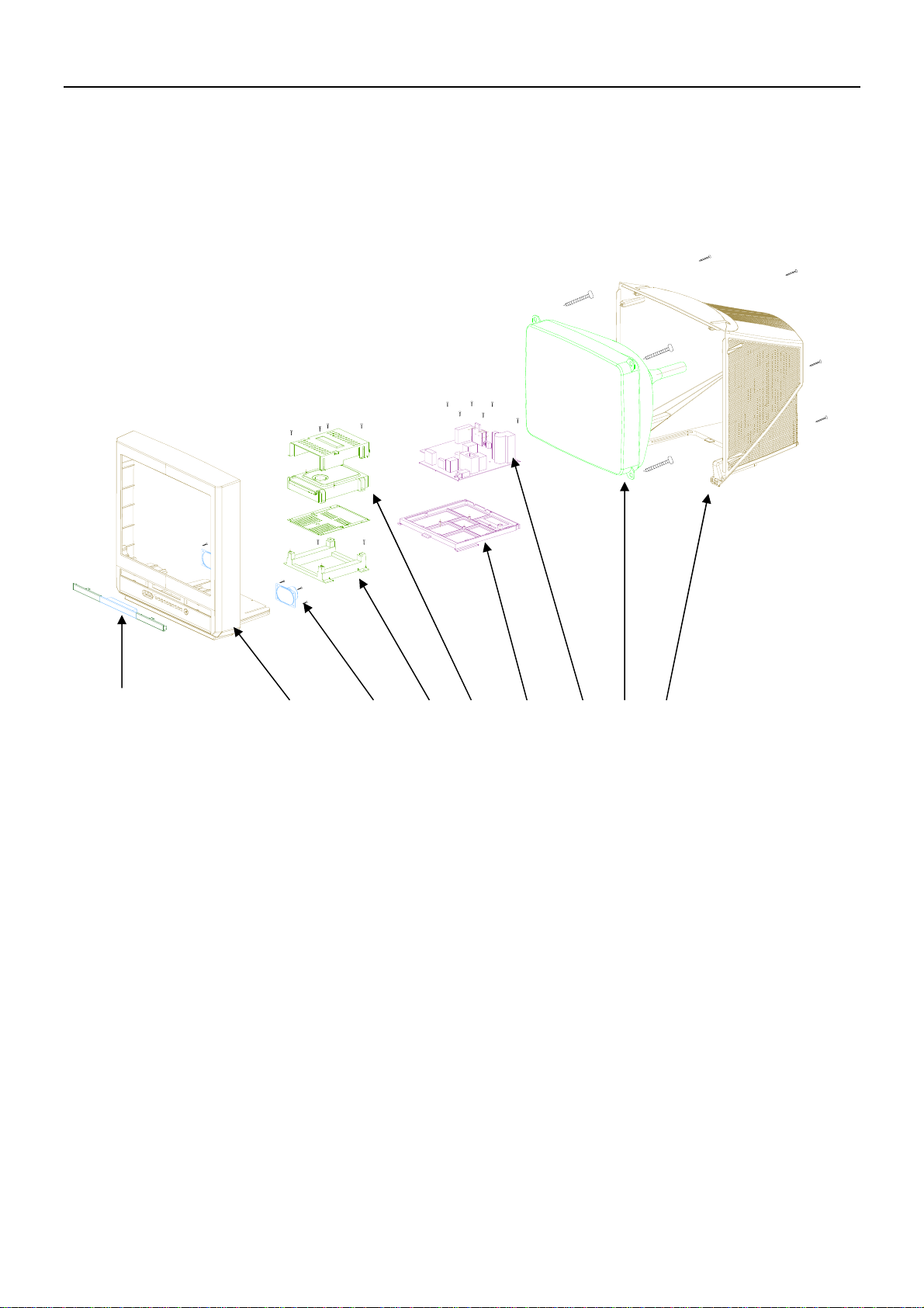
63V-330PF
C233
VD-P
50V-4.7µF
A3-15.8
A5-3.3V
R841
1K
V805
2SB764(Y)
R821
R860
2W-1Ω
1/6W-10K
R861
1/6W-1.5K
R862
V806
1/6W-15K
POWER
KSC815
R820
2W-39Ω
R807
C807
1/2W-3.3M
2kV-561pF
C808
160V-100UF
VD802
10
T1R5GU41-12.5-M
。
C810
500V-560pF
12
。
14
VD805
C811
T1R5GU41
25V-2200µF
15
VD803
T1R5GU41
16
。
C845
C846
500V-560pF
25V-1000µF
17
VD806
。
18
FFPF10U20STU
C848
C847
1000UF
19
500V-560pF
R818
1
1/2W-1.5K
C814
R819
R809
63V-104
1/2W-1K
1/2W-39K
2
DZ803
KA431
SCL
SDA
1/6W-100
R208
A6-5V
R215
3.3K
1
2
3
461
5
6
7
8
9
10
11
12
13
14
15
16
17
18
19
20
21
22
23
24
25
26
27
28
29
30
31
32
R816
1/2W-123K
R817
1/2W-2.49K
R817A
1/6W-220
STANDBY
SCL
SDA
KEY
SYSTEM
MUTE
VOL
VSSC/P
CTL
STAND BY
VSSA
SEC.PLL
VP2
DECD/G
PH2.LF
PH1.LF
GND3
DEC.BG
V.BRA
IF.IN1
IF.IN2
I.REF
V.S.C.
AGC
AV.DEEM
DECS.DEM
GND2
SND.PLL
AVL
N802
L7809CS
C829
16V-100µF
R820A
2W-36Ω
DZ802
MTZ5.1B
R824
1/2W-1
50/220/330中选用
TDA9377
N201
INSS.W2(BL)
1N4148
63V-0.01µF
AV1/AV2
XTAL.OUT
OSC.GND
AUD.OUTV.DRB
IF.VO/SVO
MTZJ9.1B
1/6W-15K
R817A调整 可调
INT.REM
AV/SVHS
XTAL.IN
CHROMA
CVPS.INT
AUO.EXT
F.B.L.SO
DZ101
VD816
A6-5V
C207
64
C234
63V-1000pF
63
62
VDDP
C236
60
16V-22µF
RESET
59
X201
12M
58
57
56
VDD.C
55
VPE
54
VDD.A
C242
63V-0.1µF
53
B.OUT
52
G.OUT
51
R.OUT
50
BLK.IN
49
BCL.IN
C250
16V-10µF
48
B2/U.IN
47
G2/Y.IN
46
R2/V.IN
BL
45
44
43
42
CVBS/Y
41
GND1
40
39
VP1
C255
16V-100µF
38
R244
1/6W-390
37
PLL.IF
R276
1/6W-27K
36
EHTO
35
34
R245
1/6W-100
33
H.OUT
R263
1/6W-200
L209
IN4004
C108
16V-47µF
A6-5V
C819
16V-100µF
A3-14.73V
2W-18KR810
R849
1/6W-10K
V804
KSC815
R848
R847
1/6W-15K
V206
R214
1/6W-10K
KSC815
1整主电压,可在
CNT01
N202
24C08
RM201
A6-5V
1
8
Wp
VDD
HS0038A
NC
PTC
A2
SCL
SDA
5
R230
1/6W-100
AV1/AV2
C237
63V-0.1µF
R238
1/6W-1K
R248
1/6W-6.8K
1/6W-1K
C246
16V-10µF
C247
50V-1uF
R275
1/6W-270K
C256
63V-0.1µF
R246
1/6W-8.2K
C249
63V-150PF
R247
1/6W-3.3K
H-DRI
AV/SVHS
R241
1/6W-4.7K
R242
C239
33
C240
33
C254
63V-0.022µF
VSS
C241
16V-100µF
R274
1/6W-22K
R249
1/6W-20K
R259
1/6W-100K
4
L206
LGA0203-100
L207
LGA0203-100
L208
LGA0203-100
R235
1/6W-100
R236
1/6W-100
R237
1/6W-100
VD201
IN4148
R243
1/6W-1K
R264
470
R265
1/6W-75
C248
63V-0.1µF
H-SYNC ABL
R943
OUT
GND
VCC
47
C922
100U
AV1/AV2
N702
9
10
10
R746
R747
11
11
3.3K
3.3K
12
12
13
13
C740
1UF
14
14
CVBS/Y
15
15
A5-3.3V
CUT-OFF
A3-5V
R273
1/6W-33K
A7-8V
R277
1/6W-100K
V213
KSC815
R250
47
V209
KSC815
VD202
IN4148
V208
KSC815
DZ205
MTZJ4.7B
16
B-OUT
G-OUT
R-OUT
R752
2
1/6W-10
C750
21P-B
50V-1uF
21P-G
21P-R
R262*
1/6W-4.7K
CVBS/Y
1N4004
L211
V210
10uH
KSR2010
C252
47u
Z203
4.5MHz
R254
180
R253
510
R252
100
R251
R256
1/6W-200
1/6W-470
R255
C253
50V-1uF
1/6W-430
TJC3-10A
CN704
TJC-2A
Y-SVHS
R718
1/6W-75
A0R
A0L
V-OUT
HEF4053
8169
7
6
5
4
V2
3
2
1
YS
C706
50V-1uF
去功放
C-SVHS
L209
R257
47
C257
47u
V212
V-OUT
KSC815
R258*
W265
1/6W-75
1/6W-1K
V211
KSR1010
SYSTEM
A7-8V
A7-8V
B4-9V
A1-33V
A2-130V
A3-15.7V
A4-10.4V
DVD-5V
A6-5V
R213
1/6W-6.2K
POWER
STAND BY
RT02
100
AV2-VIN
R715
75
SL
A2L
V04
CNS01
RS03
YC
75
C722
50V-1uF
C727
50V-1uF
9
10
10
11
11
12
12
13
14
15
15
16
SL SR
HEATER
B1-180V
A4-10.4V
MUTE
POWER
A3-15.7V
AV1-VINAV1-ALAV1-AR
CT0175RS01
102
CNS02
CN200
AV1-V
C-SVHS
Cb Cr
Y
OUT
VIDEO
AV2-L
R704
1/6W-220
N703
HEF4052
8169
7
6
5
4
3
2
1
V03
去功放
高电平有效
VOL
V04
V03
CN703
AV1-AL
AV1-AR
C001
10u
C002
10u
C003
R001
R002
10u
120
R003
120
120
R703
AV2-R
1/6W-220
R708
C705
1/6W-220
50V-1uF
A1L
A1R
R707
C725
1/6W-220
50V-1uF
R218
R233
1/6W-36KΩ
1/6W-10KΩ
VD-P
1/6W-1.2K
VD-N
DZ301
MTZJ22A
H-SYNC
B4-16.5V
A3-15.8V
V402
H-DRI
KSC2331-Y
A2-115V
HEATER
B1-185V VIDEO
ABL
R531
16K
CN001
TJC3-4Y
V531
C2688
C502
330p
CN503
CN501
TJC-5
R501
R-OUT
47
G-OUT
R-OUT
R502
47
B-OUT
G-OUT
R503
GND
47
B-OUT
CUT-OFF
CN502
TJC-3
HEATER
5
1
2
6
180V
3
7
R506
68
8
C508
10uF
R527
33K
N601
AN7522N
VCC1OUT22GND3OUT24MUTE5INPUT6GND7INPUT8VOL9OUT110GND11OUT1
R815
2W-0.18
C610
1000u
V622
KSA539
+5V
低电平有效
R605
1/6W-5.6KΩ
INPUT
INPUT2VCC3OUT4GND5VFB6OUT7VO8VI
R314
DZ303
1/6W-270K
MTZJ15C
R312
R305
1/2W-1.3
R313
1/6W-1.3K
C304
C303
100V-33uF
35V-100uF
R303
1/6W-100K
VD402
IN4004
VD401
IN4004
R403
500V-560pF
1/2W-270
C402
C401
100V-103
N301
TDA8357J
AA26-50001B
R536
270
L306
LGA0305-10uH
T401
V533
R606
R532
BF423
V503
BF423
R505
2.8
1/6W-5.6KΩ
R302
1/2W-10
C422
104
220
R512
10K
1/6W-56K
C306
63V-0.047µF
R308
1/2W-1.5
SC
C511
100Pf
C415
160V-1uF
T444
BSC25-0283G
R420
1/2W-120K
FO
HV
B
G
R
G1
CRT
A51LXR195X91JD
C510
102K/2KV
C509
SCREEN
4.7uf
R550
10M
VD507
TC2406------T
GT501 1P
GT502 1P
SPEAKER
CN601
SPEAKER
CN602
V1
V2
CN401
TJC-4
H2
H1
TO CRT
HV
HV
FO
SC
FO
SC
TO CRT PCB SCREEN & FOCUS
10 11
ABL
C414
C411
104
250V-22uF
GT404
R534
1.8K
R522
R521
220
12k
V523
R524
BF422
V521
C2688
C503
470Pf
VD504
1N4148
VD505
1N4148
1.8K
R514
1.8K
R526
270
v522
BF423
R523
ZD501
390
R512
220
R511
18K
V511
C2688
C501
470Pf
BZX79C8V2
V513
BF422
V512
BF423
R516
270
R513
390
12
VD620
W610
C612
50V-1uF
R610
1/6W-5.6KΩ
2SD2499
R407
1/2W-0.39
1N4148
C620
R622
16V-100µF
1/6W-10K
v620
R620
KSA539
1/6W-10K
V621
R621
C611
63V-4700PF
C604
50V-1uF
R611
1/6W-5.6KΩ
9
w333
1/6W-12K
R306
2W 0.68
R311
1/6W-12K
R407
1W-3.9K
DZ402
MTZJ5.1B
VD403
TC2406
C418
100V 33u
B3-18.5V
C404
25V-470uF
V401
C410
2kV-681pF
R408
1/2W-33
L402
LB3.5*5
500V-470pF
C603
63V-4700PF
C417
VD404
T1R5GU41
R307*
2W 270
C403
500V-470pF
C409
1.6KV-752
1/6W-33K
1/6W-4.7K
Ly/50µH<R307*<Ly/20µH
R415
1/2W-1
R409
1/2W-0.22
C419
2KV-681pF
C413
400V-472
R623
LW
400uH/500uH
KSC815
C621
50V-1µF
C416
400V-364
VD406
TR5GU41
2W-7.5K
R413
L401
R414
LX034
2W-1K
8
46
9
16.5
6
7
HEATER
1
H-OUT
4
5
185v
3
B+
125v
VD405
TTVR10G
V-
V+
RB05
1.8K
TU101
ENV56DB4G3
AGC
C107
16V-10µF
R110
1W-33
L102
LGA0203-100
1/6W-10
R261
R262
VD217
1/6W-9.1K
1/6W-68K
1N4148
R260
R227
1/6W-9.1K
1/6W-1K
CN801
TJC1-2Y
DV801
TVR14561
VD814
TRM11C
L801
LCL-207
Rx801
1/2W-3.3M
CN802
TJC1-2Y
P801
MZ73-14RM270V
DEGUSS
VD811
TRM11C
VD812
TRM11C
RP801
MF72-2-5Ω±N
R822
1/2W-470K
150uF/400V
R823
1/2W-470K
旧底图总号
底图总号
日期签 名
格式
(3)
更改
标记
拟 制
于鲁东
审 核
标准化 等级标记 第 张共 张
批 准
制图 描图 幅面
:::
更改
标记
21F9K拉美通用
电路原理图
更改
日期日期签 名签 名签 名数量数量数量更改单号 更改单号 更改单号
标记
W90DL-206---Q
 Loading...