

Page 1
TEAC
D V D R E C E I V E R S Y S T E M D V - C 2 0 0
STANDBY
DVD
TONE/BAL
PHONES
AUX TUNER
VOLUME/CONTRAL
V I D E O
TUNING
CD-R/CD-RW COMPATIBLE
(BAND)
DV-C200
NOTES
PC board shown are viewed from parts side.
The parts with no reference number or no parts number
in the exploded views are not supplied.
As regards the resistors and capacitors, refer to the
circuit diagrams contained in this manual.
!
Parts marked with this sign are safety critical
components. they must be replaced with identical
components - refer to the appropriate parts list and
ensure exact replacement.
DVD Receiver System
V I D E O
1 SAFETY INFORMATION
2 SPECIFICATIONS
3 ADJUSTMENT AND CHECKS
4 EXPLODED VIEW AND PARTS LIST
5 PC BOARDS AND PARTS LISTS
6 WIRING DIAGRAM
7 INCLUDED ACCESSORIES
DIGITAL OUT
CONTENTS
D I G I T A L
DOLBY
2
3
4
6
11
23
26
Page 2
DV-C200
1 SAFETY INFORMATION
SAFETY INFORMATION
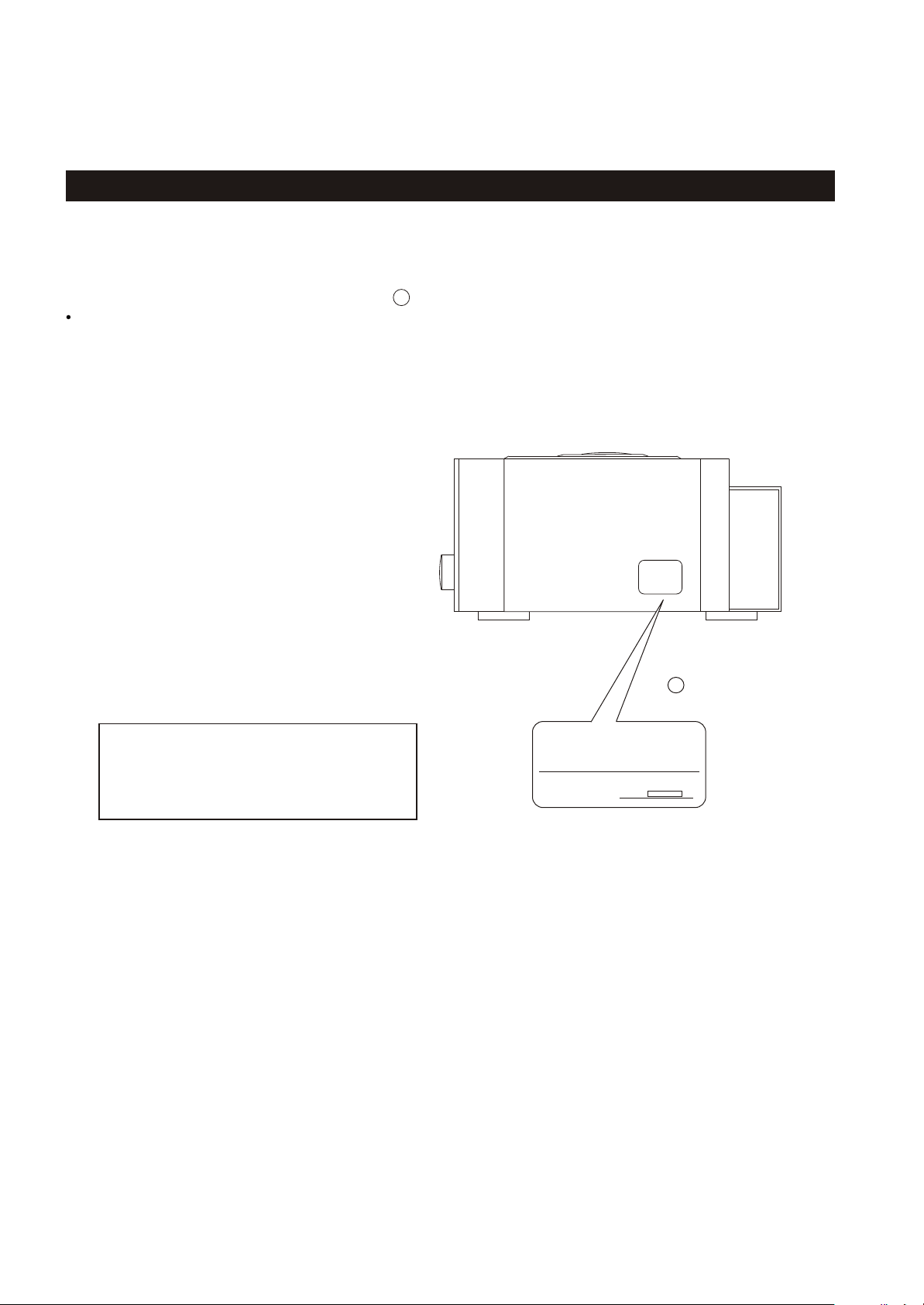
This product has been designed and manufactured according to FDA regulations " title 21, CFR, chapter 1,subchapter J,based on the
Radiation Control for Health and Safety Act of 1968" and is classified as class 1 laser product. There is not hazardous invisible laser
radiation during operation because invisible laser radiation emitted inside of this product is completely confined in the protective
housings. The label required in this regulation is shown .
CAUTION
USE OF CONTROLS OR ADJUSTMENT OR PERFORMANCE OF PROCEDURES OTHER THAN THOSE SPECIFIED HEREIN MAY RESULT IN
HAZARDOUS RADIATION EXPOSURE.
DO NOT REMOVE THE PROTECTIVE HOUSING USING SCREWDRIVER.
IF THIS PRODUCT DEVELOPS TROUBLE, MAKE A CONTACT WITH OUR SERICEMAN, AND DO NOT USE THE PRODUCT A TROUBLED STATE.
1
Optical pickup:
Type : HOP-1200
Manufacturer : Hitachi Media Electronic Co., Ltd.
Laser output : Less than 0.5 mW on the objective lens
Wavelength : 770 - 810 nm(CD),635-665nm (DVD)
1
CERTIFICATION
THIS PRODUCT COMPLIES WITH DHHS
RULES 21 CFR SUBCHAPTER J APPLICABLE AT DATE OF MANUFACTURE
TEAC. CORPORATION
3-7-3, NAKA-CHO, MUSASHINO-SHI, TOKYO, JAPAN
MANUFACTURED :
For U.S.A
2
Page 3

DVD Player
Pickup :
Signal system :
Audio frequency response :
Video output level :
S-video output level :
Tuner
System:
Tuning range :
Antenna :
Amplifier
Output power :
Total Harmonic distortion :
Frequency response :
Signal to noise ratio :
Input sensitivity :
DV-C200
2 SPECIFICATIONS
Semiconductor laser, Wavelength 650 nm
NTSC / PAL
4 Hz ~ 22 kHz (PCM 48kHz)
4 Hz ~ 44 kHz (PCM 96kHz)
1 Vp-p 75 ohms
Y: 1 Vp-p 75 ohms, C: 0.286 Vp-p 75 ohms
PLL quartz-locked digital synthesizer system
FM: 87.5 ~ 108.0 MHz (100 kHz step)
AM: 530 ~ 1710 kHz (10 kHz step)
FM pigtail antenna
AM loop antenna
15W x 2
10 % (rated power / 1kHz)
180 Hz ~ 14 kHz
Over 65dB (CCIR)
400 mV
General
Power requirements :
Power consumption :
Dimension (W x H x D ):
Weight:
Supplied accessories :
Speaker
System :
Impedance :
Unit :
Dimension (W x H x D ):
Weight:
AC 120V , 60 Hz
70 watts
(6-7/8 x 5-3/16 x 12-7/8) inches
175 x 132.5 x 327.5 mm
4.1 kg ( 9-1/16 lb)
AM loop antenna x 1
FM antenna x 1
Speaker cable (2m) x 2
Batteries (AAA, R03,UM-4) x 2
Remote Control x 1
2-way shielded box
8 ohm
3( inches) Woofer + 1(inche) Tweeter
(4-5/16 x 8-1/4 x 16-13/16) inches
110 x 210 x 173 mm
1.0 kg (2-3/16) lb
Design and specifications are subject to change without notice.
Weight and dimensions are approximate.
Illustrations may differ slightly from production model.
3
Page 4
DV-C200
3 ADJUSTMENTS AND CHECKS
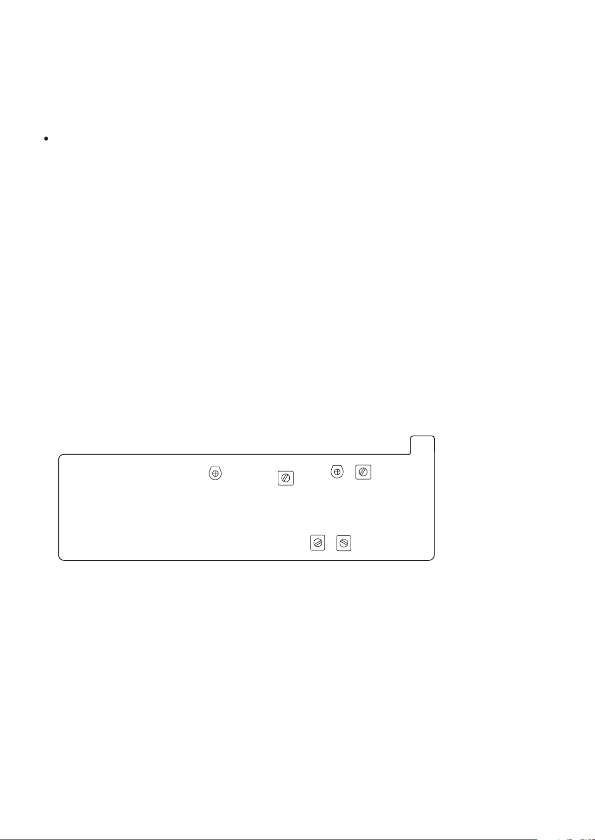
3-1 TUNER SECTION
Use a screwdriver with a plastic or ceramic grip for all adjustment.
3-1-1 FM adjustment
1. Set the function switch to the FM position.
2. Connect the signal generator output through a 75 ohm dummy
antenna to "ANT" on MAIN PCB.
3. Connect the oscilloscope to the speaker terminal.
4. Set the signal generator as listed in the alignment chart.
3-1-2 AM adjustment
1. Set the function switch to the AM position.
2. Connect the test loop antenna across the output of the signal generator.
3. Connect the oscilloscope to the speaker terminal.
4. Set the signal generator as listed in the alignment chart.
DV-C200 TUNER PCB
TC002
Fig. 3-1-3
T003
TC001
T105 T102
T002
4
Page 5

3-1-4 FM/AM alignment chart
DV-C200
ITEM
FM
1. FM band
2. Tracking
SG SETTING
87.5MHz
1kHz, +/-22.5kHz dev.
108MHz
1kHz, +/-22.5kHz dev.
90MHz
1kHz, +/-22.5kHz dev.
106MHz
1kHz, +/-22.5kHz dev.
FM IF 10.7 MHz
TUNER SETTING
87.5MHz
108MHz
90MHz
106MHz
ADJUSTMENT POINT
NIL
Should check if the
frequency is adjusted to
optimal.
NIL
Should check if the
frequency is adjusted to
optimal.
Scope / Voltmeter max.
Same as above
T105
IC101 PIN 22
ADJUSTMENT
Adjust for max.output.
Adjust for max. output
and best waveform.
AM
1. IF adjustment
2. AM band
3. Tracking
450kHz
1kHz, 30% mod
522kHz
1kHz, 30% mod
1620kHz
1kHz, 30% mod
621kHz
1kHz, 30% mod
1404kHz
1kHz, 30% mod
Repeat step 3
IC101 PIN 24
522kHz
1620kHz
621kHz
1404kHz
T102
T003
TC002
T002
TC001
Adjust for max.output.
Adjust for max. output.
Adjust for max. output
and best waveform.
5
Page 6
DV -C200
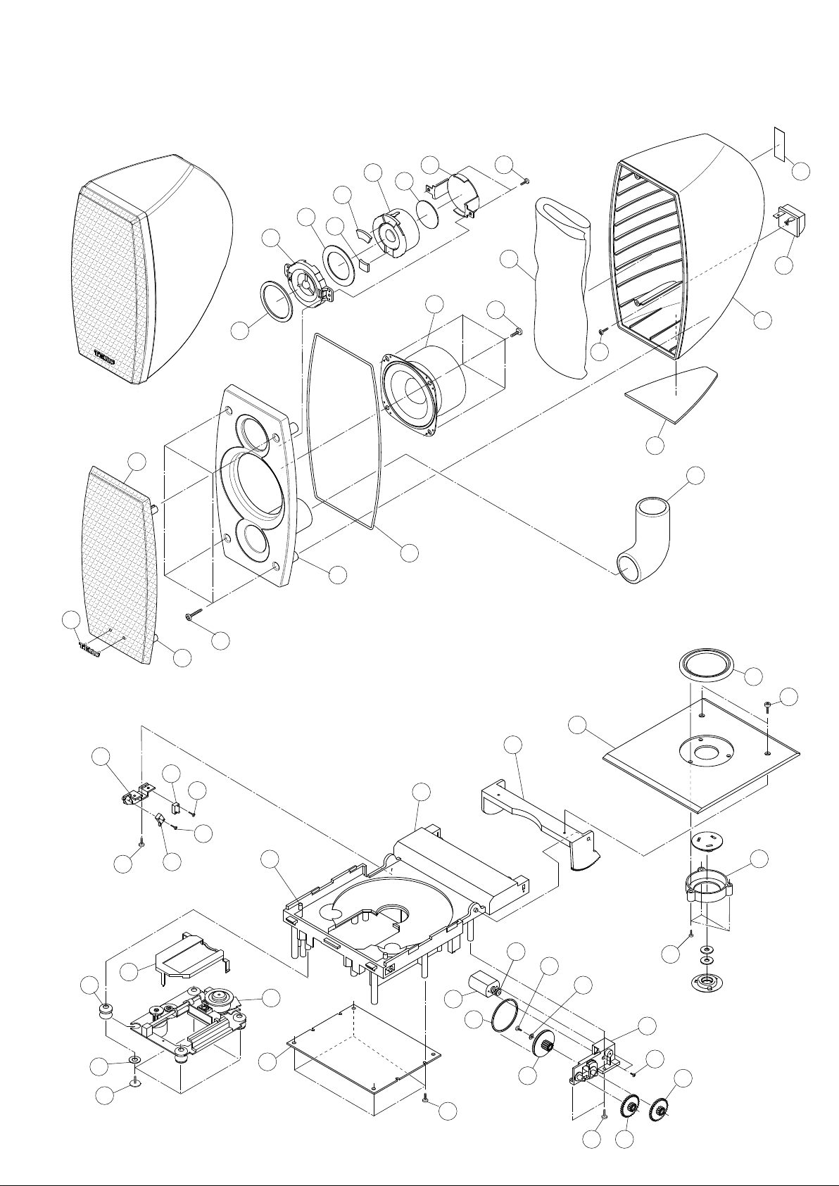
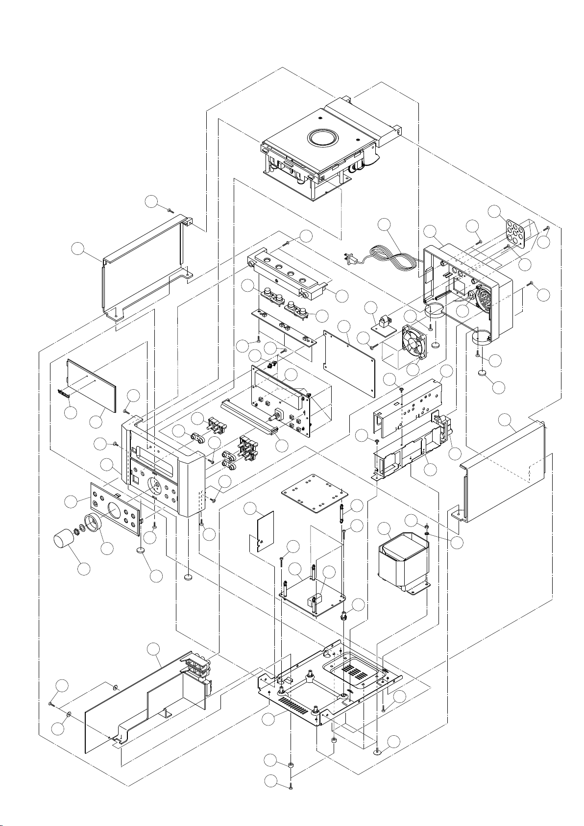
4 EXPLODED VIEWS AND PARTS LIST
EXPLODED VIEW - 1
12
22
23
18
9
10
20
23
19
17
6
5
3
2
1
4
14
8
7
16
15
11
21
1 3
EXPLODED VIEW - 2
2
12
4
16
19
20
18
14
6
7
24
24
22
9
7
8
10
26
5
11
1
25
3
17
23
6
27
13
22
22 15
21
15
Page 7

EXPLODED VIEW-1
REF. NO
1-1
1-2
1-3
1-4
1-5
PARTS NO.
IVE100227-0001
BPH100070-0001
IVE100226-0001
IVE100235-0001
IVE100235-0002
DESCRIPTION
SPONGE PAD
BRACKET
SPONGE
SPONGE
SPONGE
DV-C200
REMARKS
1-6
1-7
1-8
1-9
1-10
1-11
1-12
1-13
1-14
1-15
1-16
1-17
1-18
1-19
1-20
1-21
1-22
1-23
FSA040510-3310
IVE100239-0001
GSE100221-0001
YLB106000-0082
CJS002305-0010
BPL010014-0007
IVN000018-0005
BPG101032-0001
BPF105040-0001
BRB100040-0001
FSA011530-3310
BPR103010-0001
IVM000009-0001
IVE100225-0001
BPA100027-0001
HSP140094-3160
HSP140094-3080
HSP140054-3080
SPEAKER DRIVER
SPONGE
DRACKET
SPEAKER LABEL
SPEAKER JACK
LOGO PLATE
CLOTH
GRILL
SPEAKER FRONT PANEL
ENCLOSURE RUBBER
SPEAKER DRIVER
SPEAKER TUBE
ACOUSTIC
SPONGE
SPEAK BACK CABINET
SCREW PT4X16 MM-BLK
SCREW PT4X8 MM-BLK
SCREW PT3X8 MM-BLK
7
Page 8

DV-C200
EXPLODED VIEW-2
REF. NO
2-1
2-2
2-3
2-4
2-5
PARTS NO.
BPC100045-0001
BPN100041-0001
BPH100071-0001
BPH100068-0001
BPH100067-0001
DESCRIPTION
TOP COVER
TOP WINDOWS LENS
COVER HOLDER
HOLDER
LOADER HOLDER
REMARKS
2-6
2-7
2-8
2-9
2-10
2-11
2-12
2-13
2-14
2-15
2-16
2-17
2-18
2-19
2-20
2-21
2-22
2-23
2-24
2-25
2-26
2-27
BPH100072-0001
MSW002005-0010
BPC100046-0001
DRP041005-1001
BRB100037-0001
FMT020401-0002
BRW000008-0001
BPG001054-0001
BPH000048-0000
BPG001055-0001
BPP000007-0001
HWF11C060-6050
HWM116028-9030
HSP143073-1050
HSP140034-3061
HSP143053-3040
HSP140054-1080
HSW140054-1081
HSP140014-3070
HSH140054-1080
WVD100043-0001
SW HOLDER
MICRO SWITCH
DUST COVER
RUBBER CUSHION
TUBE
MOTOR
BELT
GEAR DRIVE
GEAR HOLDER
GEAR TURN
MOTOR PULLEY
FIBRE WASHER
WASHER
SCREW M2.6x5MM
SCREW P/H2.3x6MM-BLK
SCREW M2x4MM-BLK
SCREW PT3x8MM
SCREW P/H3x8MM
SCREW PT1.7x7MM-BLK
SCREW PT3x8MM
LOADER
SERVO PCB
8
Page 9
EXPLODED VIEW - 3
42
20
43
1
22
DV -C200
23
42
42
42
12
11
17
30
47
18
46
44
19
45
45
25
39
36
13
42
42
14
15
42
2
3
46
7
4
46
6
5
8
10
9
42
46
29
46
16
41
31
32
21
46
24
8
27
26
38
42
37
42
28
34
35
42
33
46
40
9
Page 10

DV-C200
EXPLODED VIEW-3
REF. NO
3-1
3-2
3-3
3-4
3-5
PARTS NO.
BPS100007-0001
BPL010014-0006
BPN100047-0001
BPF104017-0001
BPK105042-0001
DESCRIPTION
SIDE PANEL (LEFT)
LOGO PLATE - SILVER
FRONT WINDOW LENS
FRONT PANEL
VOLUME KNOB
REMARKS
3-6
3-7
3-8
3-9
3-10
3-11
3-12
3-13
3-14
3-15
3-16
3-17
3-18
3-19
3-20
3-21
3-22
3-23
3-24
3-25
3-26
3-27
3-28
3-29
3-30
BPK105041-0001
BPF104016-0001
BRF100028-0001
BPN100094-0001
BPK108059-0001
BPT100012-0001
BPK102060-0002
BPK102060-0001
DSS100011-0001
APE100158-0001
BPN100048-0001
APE100157-0001
APE100155-0021
FAN021203-0004
VPA004252-0010
!
DBU001006-0010
BPQ100001-0003
BNP100073-0001
GTP100010-0001
GTP100004-0001
APE100160-0001
BPS100008-0001
APE100156-0001
BPH100080-0001
DSS100001-0002
VOLUME RING
FRONT CABINET
RUBBER FOOT
KNOB LENS
FUNCTION KNOB (FRONT)
TOP COVER
FUNCTION KNOB(OPEN AND PAUSE)
FUNCTION KNOB (TOP)
SUPPORT
CONTROL PCB ASSY
LED WINDOW
MPEG PCB ASSY
OPTICAL PCB ASSY
DC FAN 12V
LINE CORD
AC LINE CORD BUSHING
BACK CABINET
PVC PLATE
TIN PLATE
TIN COVER
TUNER PCB ASSY
SIDE PANEL (RIGHT)
AMP PCB ASSY
BRACKET - ABS
SPACER
3-31
3-32
3-33
3-34
3-35
3-36
3-37
3-38
3-39
3-40
3-41
3-42
3-43
3-44
3-45
3-46
3-47
APE100155-0011
DCR030001-0001
BPH100066-0001
GSE100173-0001
DHU210002-0001
!
TTH112000-0040
HWG11 1035-6100
HWT168540-1100
HNT140700-1300
HSD143103-1080
HST143084-1150
HSP140054-1080
HSP140054-1100
HSP140054-1160
HSW143083-1040
HSP143084-1080
HST143084-1140
POWER PCB ASSY
FUSE COVER
PCB HOLDER
BOTTOM
WASHER NYLON
TRANSFORMER 120V 60Hz
FIBRE WASHER D10x3.5x1MM
WASHER D8.5x4x1MM
NUT- M4x7x3MM
SCREW M4x8MM
SCREW M3x15MM
SCREW PT3x8MM
SCREW PT3x10MM
SCREW PT3x16MM
SCREW M3x4MM WASHER HEAD
SCREW M3x8MM
SCREW M3x14MM
10
Page 11

5 PC BOARDS AND PARTS LIST
AMPLIFIER PCB ASSY - TOP
REF. NO
CN601
FB802-804
IC400,402-405
PARTS NO.
APE100156-0001
LVM100156-0001
CCH100010-0628
SCB008050-6010
RCI004558-0001
DESCRIPTION
AMPLIFIER PCB ASSY
AMPLIFIER PCB
CONNECTOR 28PIN P=1MM
CHIP BEAD 600 OHM
IC - JRC4558D
DV-C200
REMARKS
IC406
IC500
IC501
RCI062426-0001
RCI002702-0001
RCI007440-0001
IC - M62429P
IC - NJM2702
IC - TDA7440D
11
Page 12

DV-C200
AMP PCB - TOP
12
Page 13

AMPLIFIER PCB ASSY - BOTTOM
REF. NO
CN301
CN900
CN901
C926-928,935
C988,989
C903,904,919,996
C934
D300,301,500-506
D901-904,906,913,
D914
PARTS NO.
CCN200000-0106
CCH100060-0616
CCN200000-0103
!
PVE039550-1020
!
PVE939550-2220
!
PDE039550-4720
RAD114001-0010
DESCRIPTION
CONNECTOR 6PIN P=2MM
CONNECTOR 16PIN P=2MM
CONNECTOR 3PIN P=2MM
CE - 25V 1000UF
CE - 25V 2200UF
CE - 25V 4700UF
DIODE 1N4001
DV-C200
REMARKS
D905,912
D911
IC502
IC900
IC901
IC902,903
JK501
JK580
JK801
L500,501
Q400-402
Q500-502,505,521,
Q901,903,912,914,
Q916,920,925
Q503,522,801,850
Q900,902,906,907,
Q909,910,911,913,
Q915,917,918,919
Q921,922,923
Q905,908
ZD901
ZD902
!
RHD115401-0010
!
RHD204060-0010
RH1007269-0001
RHI007812-0001
RHI007912-0001
RHI007805-0005
CJR006401-0020
CJR042003-0010
CJC010001-1010
SFB001001-0030
RAN202878-0001
RAP200733-0001
RAN200945-0001
RHP200772-0001
RAZ005009-0010
RAZ005006-0030
DIODE IN5401
BRIDGE - RS405
IC - TDA7269A
IC-7812
IC-7912
IC-BA05T
RCA JACK 6P
SPK JACK 4P
RCA+DIN JACK 4P
BEAD FERIT 100 OHM
TR-2SC2878
TR-2SA733
TR-2SC945
TR-2SB772
ZENER DIODE 9V
ZENER DIODE 6V
13
Page 14

DV-C200
AMP PCB - BOTTOM
14
Page 15

DV-C200
MPEG PCB ASSY - TOP
REF. NO
CN101
CN202
CN601
CN602
CN800
D201-208,210
FB201,
FB204,210
FB601
IC201
IC202
IC204
IC205
IC206
IC601
L201-204
Q201
Q203
Q205
RL203-205
RL202,208-216
RL206,207
XL201
PARTS NO.
APE100157-0001
LFF100157-0001
CCN200000-0112
CCN254020-0440
CCH100010-0628
CCN200000-0104
CCN200000 -0106
RCD104148-0010
SCB008050-1010
SCB008050-6010
RCI006018-0001
RCI400160-0001
RCI024002-0001
RCI916433-0001
RCI290080-0001
RCI004340-0001
SCN023500-2490
RAN202001-0001
RHP200733-0001
RAN200945-0001
QCP015081-1000
QCP015081-3300
QCP015081-4700
JQC023101-2760
DESCRIPTION
MPEG PCB ASS'Y
MPEG PCB
CONNECTOR 12PIN P=2MM
CONNECTOR 20x2 PIN
CONNECTOR 28PIN
CONNECTOR 4PIN P=2MM
CONNECTOR 6PIN P=2MM
CHIP DIODE 1N4148
CHIP BEAD 100 OHM
CHIP BEAD 600 OHM
IC-ES6018
IC-4MX16 Y3VTW
IC-AT24C02
IC-RT9164-33CLR
IC-AM29F080B
IC-CS4340
CHIP INDUCTOR 2.4UH
TR-2SC2001L
TR-2SA733
TR-2SC945
RES ARRAY 10 OHMx4
RES ARRAY 33 OHMx4
RES ARRAY 47 OHMx4
CRYSTAL 27MHZ
MPEG PCB ASSY - BOTTOM
REF. NO
FB202
IC602,603
PARTS NO. DESCRIPTION
SCB008050-1010
RCI740374-0002
CHIP BEAD 100 OHM
IC-74HC374
15
Page 16

DV-C200
MPEG PCB - TOP
MPEG PCB - BOTTOM
16
Page 17

DV-C200
CONTROL PCB ASSY - TOP
REF. NO
APE100158-0001
D201-203
DP201
JK300
LD201
LD202-208
Q201,202,301
Q203
SN201
TA201-210
VR201
ZD201
LVC100158-0001
RAD114148-0010
KLV000005-0010
CJM035010-1010
KED300205-0010
KED600005-0030
RAN200945-0001
RAP200733-0001
RHO200038-0001
MAW060001-0010
MSW005009-0010
RAZ005005-0030
DESCRIPTIONPARTS NO.
CONTROL PCB ASSY
CONTROL PCB
DIODE 1N4148
VFD 83.2x17mm
PHONE JACK 6P
LED - ORANGE 2x5mm
LED -BLUE D5MM
TR-2SC945
TR-2SA733
IRT SENSOR RIMB38F
SW SKHVBE3520
ROTARY VOLUME
ZENER DIODE 5.2V
CONTROL PCB ASSY - BOTTOM
REF. NO
FB300,301
IC201
IC300
PARTS NO. DESCRIPTION
SCB008050-6010
RCI006311-0001
RCI052280-0001
CHIP BEAD 600 OHM
IC-PT6311
IC-PT5228
17
Page 18

DV-C200
CONTROL PCB - TOP
8
JK300
CONTROL PCB - BOTTOM
18
Page 19

DV-C200
TUNER PCB ASSY - TOP
REF. NO
CF101
CF102
CF103
D001-004,D101
EF001
JK1
L102,104,153,154
L103
Q001
Q101,102
Q103
Q104,105
T001
T002
T003
T101
T102
T103,104
T105
TC001
TC002
VD001,002
XL152
PARTS NO.
APE100160-0001
LVT100160-0001
JFT005002-0020
JFT005002-0040
JFT005001-0030
RAD114148-0010
WTP000005-0001
CJA001005-2010
SAN001600-1000
SAN001600-3930
RAM200192-1001
RAN201675-0001
RAP200733-0001
RAN200945-0001
SIL013012-0010
SIL013009-0011
SIL013010-0012
SIL016001-0010
SIF010001-0040
SIL016001-0020
SIF020001-0050
MVC001001-0010
MVC001002-0010
RHV100149-0001
JQC013101-4550
DESCRIPTION
TUNER PCB ASSY
TUNER PCB
CER. FILTER SFE10.7MA
CER. FILTER SFE10.7MS3
CER. FILTER 450KHZ
DIODE 1N4148
TUNER PACK- FTE3-500H
ANT JACK
INDUCTOR 10UH
INDUCTOR 39mH
TR-2SK192A
TR-2SC1675
TR-2SA733
TR-2SC945
OSC COIL
AM ANT OSC -0A10
OSC COIL -502522
BIAS COIL -865807
AM IFT - 455KHz
BIAS COIL - 865806
FM IFT - 10.7MHz
TRIMMER 3-10PF
TRIMMER 4.2-20PF
DIODE ISV149B
CRYSTAL 4.5MHZ
TUNER PCB ASSY - BOTTOM
REF. NO
IC101
IC152
PARTS NO.
RC1001837-0001
RC1072131-0001
DESCRIPTION
IC - LA1837
IC - LC72131M
19
Page 20

DV-C200
TUNER PCB - TOP
EF001
20
TUNER PCB - BOTTOM
Page 21

DV-C200
POWER PCB ASSY
REF. NO
CN901,907
CN908,977
F902,904-906
F903,908,909
PARTS NO.
APE100155-0011
LVP100155-0011
CCN250000-0113
CCN396021-0104
!
KSA020160-0030
!
KSA020315-0030
DESCRIPTION
POWER PCB ASSY
POWER PCB
CONNECTOR 13PIN P=2.5MM
CONNECTOR 4PIN P=3.96MM
FUSE 1.6A 250V
FUSE 3.15A 250V
OPTICAL PCB ASSY
REF. NO
CN352
CN353
JK353
PARTS NO.
APE100155-0021
LVP100155-0021
CCN200000-0105
CCN250000-0102
CJT100001-0001
DESCRIPTION
OPTICAL PCB ASSY
OPTICAL PCB
CONNECTOR 5PIN P=2MM
CONNECTOR 2PIN P=2.5MM
JACK TOTX178A
21
Page 22

DV-C200
POWER PCB
OPTICAL PCB
22
Page 23

6 WIRING DIAGRAM
DV-C200
AMP PCB - BOTTOM
TO TUNER PCB RB101
TO CONTROL PCB RB301
TO MPEG PCB CN601
TO CONTROL PCB RB900
CN601
23
Page 24

DV-C200
POWER PCB
TO AMP PCB RB907
TO TRANSFORMER
TO TRANSFORMER
OPTICAL PCB
TO AMP PCB RB352
TO AC LINE CORD
TO DC FAN
24
Page 25

DV-C200
MPEG PCB - TOP
TO TUNER PCB RB101
CN101
TO SERVO PCB J2
CN202
CN800
TO AMP PCB RB800
CN602
1234
TO AMP PCB RB401
25
Page 26

DV-C200
INCLUDED ACCESSORIES
REF. NO
PARTS NO. DESCRIPTION
7 INCLUDED ACCESSORIES
REMARKS
YWC100016-0001
YOM100138-0001
VTA100001-0020
VTA400001-0020
VWS331044-2000
FBY064015-0003
AIR151009-0029
WARRANTY CARD
INSTRUCTION BOOK
AM LOOP ANTENNA
FM ANTENNA
SPEAKER CABLE x 2
BATTERIES (AAA,R03, UM-4) x2
REMOTE CONTROL
26
Page 27

DV-C200
TEAC CORPORATION
TEAC AMERICA, INC.
TEAC CANADA LTD.
TEAC MEXICO, S.A.De C.V.
TEAC UK LIMITED
TEAC DEUTSCHLAND GmbH
TEAC FRANCE S.A.
TEAC NEDERLAND BV
TEAC BELGIUM NV/SA.
TEAC ITALIANA S.p.A.
TEAC AUSTRALIA PTY., LTD.
A.B.N. 80 005 408 462
3-7-3 Nakacho, Musashino-shi, Tokyo 180-8550, Japan Phone:(0422)52-5081
7733 Telegraph Road, Montebello, California 90640 Phone: (323)726-0303
5939 Wallace Street, Mississauga, Ontario L4Z 1Z8, Canada Phone: (905)-890-8008
Campesinos 184,Col. Granjas Esmeraida, 09810, Mexico Phone: (525)-581-5500
5 Marlin House, Croxley Business Park, Watford, Hertfordshire, WD18 8TE, U.K. Phone: 01923-819699
Bahnstrasse 12, 65205 Wlesbaden-Erbenheim, Germany Phone:0611-71580
17, Rue Alexis-de-Tocqueville, CE 005 92182 Antony Cedex, France Phone:(1)42.37.01.02
Oeverkruid 15,NL-4941 W Raamsdonksveer, Nederland Phone:0162-510210
c/o TEAC NEDERLAND BV, Oeverkruid 15, NL-4941 W Raamsdonksveer, Nederland Phone:+31-162-510860
Via C, Cantu 11, 20092 Cinisello Balsamo, Milano, Italy Phone:02-66010550
280 William Street, Melbourne, VIC 3000, Australia Phone:(03)9672-2400
PREPARED IN HONG KONG
Page 28

AMPLIFIER PCB
R851
200
R850
100
JK501
R430
4.7K
C424
4.7UF
C423
4.7UF
C427
C428
101
101
SUB-PRE
R427 4.7K
C453
224
C454
224
R467
12K
C402
101
C426
101
R424 47K
LO
RO
R425 47K
--
C
425
101
R428 47K
R432
R468
10K
C456
224
C455
224
1K
R469
12K
R40122K
R43322K
R436 1K
R434 1K
C429
C457
104
C458
473
R435 1K
C430
2
3
6
5
2
3
R470
47K
6
5
561
R438
4.7K
4
104
C431 561
R439 4.7K
8
C416
104
R440 100
IC405A
4
8
4558D
1
IC402A
4558D
IC402B
4558D
C433
4.7UF
1
C
459
104
IC405B
C
104
R852
1K
R422 100K
R421 100K
Q400
2SC2827
R437
100
C434
4.7UF
7
7
4558D
460
1K
R441
e
C461
4.7UF
c
D5V
R855
10K
Q850
2SC945
CN900
CN601
123456789101112131415161718192021222324252627
STANDBY
C447
391M
VOL1
TU-POWER
C420
102M
R462 10K
C446
391M
R460 NC
C448
102M
R461
C509
472M
3D
R63 10K
NC
R561
R560
14
LIN
IC500
NJM2702
1
C508
10uF
R502 10
SPDIF
VFD-CLK
TUN-DI
VFD-DATA
REMOTE
TUN-SD
74/62-DATA
C422
104
4
3
2
R464 0
C451
C449
104
8
5
6
R465 0
52
C4
R527 1K
R526 1K
NC
NC
11
12
13
RIN
LOUT
ROUT
R505
C506
0
1uF
D5V
LED
R856
100
b
R471
1K
R429
C475
C414
104
8
IC403B
R442
C435
4.7K
C993
104
R443
4.7K
Q401
2SC2827
R506
5.6K
4.7U
R444
1K
C436
4.7UF
R445
1K
C519
1UF0805
C554
104M
C992
100uF
C521
1UF0805
C507 104M
C555
C524
ZD902
6V
R-O UT
Q402
Q925
2SA733
123
2SC2827
678
4 5
L-OUT
R949
3.3K
C474
47K
10uF
10uF
IC406
M62429P
4558D
C438
R446
IC403A
4558D
C437
R507
5.6K
C520 104M
13
14
BIN-L
BOUT-R
BOUT-L15MOUT- L16MIN-L17T-R19T-L
104M
562M
C522 562M
C523 10uF
74/62-CLK
74/62-DATA
C439
104
4
R447
22K
11
12
BIN-R
MOUT-R
IC501
18
Q910
2SC945
22K
10
47P
47P
9
MIN-R
20
C991
220uF
5
6
3
2
8
SOUT-R
D-GND
21
R448
10K
R449
10K
C510
C546
AUX-L
TUN-L
10uF
C550
C551 10uF
7
6
L-IN4
L-IN25L-IN3
SOUT-L
TDA7440D
F
L
SC
SDA22CRE
23Vs24
R926
2R2
R927
470R
R450
100K
R415
100K
1UF0805
1UF0805
270R
R528
C514 10uF
2
3
4
L-IN1
R-IN1
AGND25ROUT26LOUT27R-IN4
C513 100uF
C441
4.7UF
1
R-IN2
28
R510
100
C440
4.7UF
R452
1K
R453
1K
-L
CD
-
R
CD
270R
R513
AUX-R
TUN-R
C512 10uF
C515 10uF
C516 10uF
R-IN3
C511 104
ZD901
9V
C561
4.7UF
C560
4.7UF
TUN-L
Q909
2SC945
R454
3.3K
C443
10UF
R455
3.3K
CN901
N-R
TU
R501
1K
C500
561
C502
561
R500
1K
R924 2R2
R925 220R
C990
220uF
C442
10UF
RDS-DATA
R458
R456
5.1K
5.1K
C444
101M
R457
R459
5.1K
5.1K
C445
101M
123
C501
4.7UF
R550
4.7K
R551
4.7K
C503
4.7UF
+12V
POWER BOARD
R910 1
CN907
CON13
1
2
3
4
5
6
7
8
9
10
11
12
13
R911 1
R912 1
F902 T1.6A L 250V
!
F904 T1.6A L 250V
!
F905 T1.6A L 250V
!
F906 T1.6A L 250V
!
R914 1
R913 1
F903 T3.15A L 250V
!
F909 T3.15A L 250V
!
F908 T3.15A L 250V
!
TUN-DO
C421
100UF
IC404A
4558
C450
100UF
IC404B
4558
10
NC
1KV 103
28
C
N
+8V
EAR
R407
1K
R408
1K
5
6
IC400A
4558D
3
2
C527
471
C528
471
+15V
400
12
11
10
9
8
7
6
5
4
3
2
1
..
12pin2.0
C405
8
IC400B
R409 1K
C406 47P
C407
104
R4101K
C408 47P
C533
47uF
C529
4.7uF
C530
471
C531
471
C532
4.7uF
C534
47uF
CN301
1
2
3
4
5
6
104
4558D
7
R538
100K
1
11
C538
R518
560
7
9
R519
560
Q505
2SA733
GND
104
C409
4.7UF
C410
4.7UF
810
TDA7269A
C309
10UF
C539
R539
10K
+15V
IC502
--
1
-15V
1uF
R530
15K
3
6M5
C802
JK801
15P
1
2
3
4
5
6
7
S-VIDEO
R540
18K
C537
104
R522
4.7R
+
4
C556
104M
2
C540
104M
--
R541
18K
R559
220K
Q503
2SC945
R311
10K
LK
UN-C
TUN-CE
T
VFD-CS
74/62-CLK
MUTE
-12V
NC
+12V
7
NC
3D
9
8
NC
SW
GND7V+6VREFIN5NC4VOL3NC2FIL
C504
100uF
C505
104
R503
47K
TU12V
C545
471
TU5V
C544
C472
224M
471
C470
224M
R403 22K
R405
47K
R404 22K
C471
224M
R406
R514
1K
TUN-SD
TUN-DO
TUN-CLK
TUN-DI
TUN-CE
RDS-DATA
RDS-CLK
C473
224M
47K
R515
1K
R517
10K
R516
10K
RDS-CLK
VOL2
R535
10K
C535
10uF
TRANSFORMER
!
CN901
1
2
3
4
5
6
7
8
9
10
11
12
13
CN977
4
3
C977
2
1
CN908
4
3
2
1
RB909
CN901
1
2
3
4
5
6
7
8
9
10
11
12
13
1
2
3
4
AC IN
RB977
4
3
2
1
!
C801
R521
4.7R
15P
R531
4.7K
Q502
2SA733
FB802 600
FB803 600
FB804 600
C803
15P
L501
100
C542
272
JK580
C541
272
L500
100
1N4001
R529
10K
+15V
C918
104
15V
+
VGND
D505
C997
104
RB401
4
4P SPK
D301
1N4001
123
C919
2200UF
!
C921
104
R570
100K
Q521
2SA733
RB352
CON3
Q921
2SC945
D500
1N4001
1N4001
C996
2200UF
D506
1
!
R941
1K
C543
470UF
C920
104
R571
4.7K
RB800
6P 2.0
VGNDVGND
123
1
2
3
4
5
6
Q919
2SC945
R942
1K
D300
1N4001
2
3
D5V
D911
RS405
C922
2SC945
!
104
CN352
CON5
R572
4.7K
Q522
C
L-OUT
R-OUT
Q500
2SA733
D501
1N4001
4
5
4
3
2
1
SCART1
SCART2
D-GND
CVBS
C/V/ R
Y/G
U/B
Q922
2SC945
VGND
Q920
2SA733
R945
10K
VGND
D502 1N4001
R523
Q501
2SA733
C557
1UF
C923
104
FANFAN+
R943
R532
22K
FAN
-+
2
C800
1K
2
10U
VGND
Q923
2SC945
10K
C558
47UF
1
1
R354
R355
CN353
2PIN2.5
100
OPTICAL BOARD
F
10UF
Q918
2SC945
R947
4.7K
STANDBY
R525
6.8K
R533
4.7K
100
C381
100UF
R944
1K
R524
3.3K
AC2
+12V
R802
10K
SCART2
Q801
1
2
3
4
5
6
7
8
9
10
11
12
13
14
15
16
D504
1N4001
D503
1N4001
RB902
4
3
2
1
TO LOADER
JK353
GPIF32T
2SC945
C900
220UF
D5V
104
C925
104
TU5V
924
2SC945
+12V
-12V
Q900
C901
104
C902
104
3
C926
1000UF
3 IC903
C927
1000UF
-POWER
R900
1K
DVD POWER
!
!
1000UF
CN801
CON16
D5V
C559
33UF
C380
104
16
EAR
Q901
2SA733
IC902
BA05T
BA05T
!
C928
REMOTE
VFD-CS
R801
10K
D5V
R901
22K
R903
10K
R902
10K
3 IC900
7812
!
C903
2200UF
!
C904
2200UF
1
IC901
3
7912
1
2
1
2
C994
CON16
SCART-1
VFD-CLK
SCART-2
2
104
930
C
104
VFD-DATA
C905
220UF
1
2
VOL1
LED
TU12V
C906
104
C907
104
Q905
2SB772
DVDPOWER
C931
220UF
VOL2
Q902
2SC945
Q906
2SC945
Q907
2SC945
D5V
R904
R916
123456789101112131415
AC1
Q903
2SA733
1K
!
C988
1000UF
!
C989
1000UF
2SB772
1K
2SC945
2SA733
CN908
2PIN2.5
R907
R917 22K
R918
560
Q908
R919
22K
Q911
Q912
1
2
Q915
2SC945
+12V
22K
R909
10K
R908
D902
R920
10K
R921
10K
R923
R922
10K
10K
10K
R933
100K
Q913
2SC945
2V
-1
D903
1N4001
C910
104
D904 1N4001
C911
104
C908
104
D901
C909
104
1N4001
C932
104
C933
104
R931
2.
R938
2.2K
2SA733
1N4001
4700UF
C935
1000UF
2K
Q916
C934
R934
!
!
SN901
PTC
R937
100K
Q914
2SA733
15K
Q917
2SC945
R939
10K
D905
1N5401
C936
104
D912
C937
104
1N4001
D913
C938
D914
C939 104
104
1N4001
1N5401
DV-C200
DVD Receiver System
R935
15K
R940
!
!
R936
9.1K
+5V
2.2K
LED
R932
10K
C913
100UF
D906
1N4001
RB907
13P 2.5MM
1
2
3
4
5
6
7
8
9
10
11
12
13
Page 29

MPEG PCB
Pull high ES4438 pin 41 to use DCLK for cloc k source, no need for XIN/XOUT crystal c ircuitr y
2 Ground are connected at board layout thru a thic k trace cr ossing R279
VCC
R650
1K
R653
R654
1M
DRDQ#
DWRQ#
IC206
DD0
DD1
DD2
DD3
DD4
DD5
DD6
DD7
DD8
DD9
DD10
DD11
DD12
DD13
DD14
DD15
AM29F080B
22K
Q203
2SA733
Q205
2SC945
R651
10K
R652
47K
12
A0
A1
A2
A3
A4
A5
A6
A7
A8
A9
A10
A11
A12
A13
A14
A15
A16
A17
A18
A19
CE
OE
R237 33 OHM
R263 33 OHM
RL208 33x4
RL211 33x4
LA0
11
LA1
10
LA2
9
LA3
8
LA4
7
LA5
6
LA6
5
LA7
27
LA8
26
LA9
23
LA10
25
LA11
4
LA12
28
LA13
29
LA14
3
LA15
2
LA16
30
LA17
31
1
22
24
INSTALL REMOVE TYPE
R39, R41 R40,
R42 R39,
R40,
2
4
RL206 47x4
1 8
2
3
4
RL207 47x4
1 8
2
3
4
1 8
2 7
3 6
4 5
RL209 33x4
1 8
2
3
4 5
RL210 33x4
1 8
2
3 6
4 5
4 5
3 6
2
1 8
RL212 33x4
1 8
2 7
3 6
4
D210
1N4148
C650
224
8MBIT EPROM
13
LD0
LD1
LD2
LD3
LD4
LD5
LD6
LD7
VCC
RST#
DRDQ#
DWRQ#
DRST#
DRD#
DWR#
DIORDY
DIOCS16#
DACS1#
DACS3#
DIRQ
DD[0..15]
D0
14
D1
15
D2
17
D3
18
D4
19
D5
20
D6
21
D7
32
VCC
16
GND
LD[0..7]
RESET1CLK/CE1
WE3ADDR/CE1
ROM EMULATOR SOCKET
4-PIN EXTENSION FOR ROM EMULATOR INTERFACE
DRST#
DRD#
DWR#
DIORDY
DIOCS16#
DACS1#
DACS3#
DIRQ
DA0
DA0
DA1
DA1
DA2
DA2
INSTALL REMOVE CLK SOURCE
R3 R4 DCLK INPUT
R4 R3 CRSTAL OSC
C651
15P
LCS1#
LCS2#
WRHL#
LOE#
LA[0..19]
LA19
LA18
R239 OPEN
R240 0 OHM
R242 0 OHM
R42
FLASH
R41
EPROM
OPEN
R238
LCS2#
LD [ 8. . 15]
7
6
5
7
6
5
HD0
7
HD1
6
HD2
HD4
HD5
7
HD6
HD7
HD8
HD9
HD10
7
HD11
HD12
HD13
HD14
HD15
5
27M
RST#
LA21 LA21
HRST#
HRD#
HWR#
HIORDY
HIOCS16#
HCS1#
HCS3#
HIRQ
HA0
HA1
HA2
LCS1#
LCS2#
LCS3#
WRLL#
WRHL#
LOE#
HRDQ#
HWRQ#
LA0
LA1
LA2
LA3
LA4
LA5
LA6
LA7
LA8
LA9
LA10
LA11
LA12
LA13
LA14
LA15
LA16
LA17
LA18
LA19
LD0
LD1
LD2
LD3
LD4
LD5
LD6
LD7
LD8
LD9
LD10
LD11
LD12
LD13
LD14
LD15
VCC
R201
4.7K
R202
OPEN
(4.7K)
105
CLK
24
RESET
173
LCS0
174
LCS1
175
LCS2
176
LCS3
198
LWR LL
199
LWR HL
170
LOE
204
LA0
205
LA1
206
LA2
207
LA3
2
LA4
3
LA5
4
LA6
5
LA7
6
LA8
7
LA9
10
LA10
11
LA11
12
LA12
13
LA13
14
LA14
15
LA15
16
LA16
19
LA17
20
LA18
21
LA19
22
LA20
23
LA21
178
LD0
179
LD1
180
LD2
181
LD3
182
LD4
185
LD5
186
LD6
187
LD7
188
LD8
189
LD9
190
LD10
191
LD11
194
LD12
195
LD13
196
LD14
197
LD15
145
HRST/EAUX3 [5]
150
HRD/DCI_ ACK/EAUX4[6]
149
HWR/DCI_ CLK/EAUX4[5]
143
HRDQ/EAUX4[0]
142
HWRQ/DC I_REQ/ EAUX4[1]
146
HIORDY/EAUX3[3]
151
HIOCS16/ CAMPCLK/EAUX3[ 4]
152
HCS1FX/E AUX3[7]
153
HCS3FX/E AUX3[6]
144
HIRQ/DCI _ERR/EAUX4 [7]
154
HA0/EAUX4[2]
155
HA1/EAUX4[3]
158
HA2/EAUX4[4]
122
HD0/DCI[0]/E AUX1[0]
123
HD1/DCI[1]/E AUX1[1]
124
HD2/DCI[2]/E AUX1[2]
125
HD3/DCI[3]/E AUX1[3]
126
HD4/DCI[4]/E AUX1[4]
127
HD5/DCI[5]/E AUX1[5]
128
HD6/DCI[6]/E AUX1[6]
131
HD7/DCI[7]/E AUX1[7]
132
HD8/DCI_F DS/EAUX2[0]
HD9/EAUX2[1]
134
HD10/EAUX2[2]
135
HD11/EAUX2[3]
136
HD12/EAUX2[4]
137
HD13/EAUX2[5]
140
HD14/EAUX2[6]
141
HD15/EAUX2[7]
OPEN
R267
31
Pull high
25
28
TDMTSC
TDMDX/RSEL
42
OPEN
R268
TDMDX
R245
R246
R247
29
30
TDMFS
TDMDR
TDMCLK
NC/CAMVS
CAMYUV0
203
202
112
OPEN
R269
to select
8-bit ROM boot, pull low to select 16-bit ROM boot
INSTALL REMOVE FREQ
R6, R8 R5, R7 121.5MHz
R5, R8 R6, R7 81.0 MHz
R6, R7 R5, R8 94.5 MHz
R5, R7 R6, R8 108.0MHz
33 OHM
33 OHM
33 OHM
VCC33VCC33E VCC33P
FB201
100
FB202
100
1
51
111
VC33
AVCC(PLL)
AVCC(VDAC)
18
VC33
27
VC33
VC3359VC3368VC3375VC3392VC33
99
104
IC201
ES6018
VSS
VSS
VSS
OPEN
R272
VSS
17
43
26
34
OPEN
R273
CAMYUV1
OPEN
R270
8
52
OPEN
R271
AVSS(PLL)
AVSS(VDAC)
TDM-DATA
TDM-FS
TDM-CLK
VCC33
148
130
VC33
VC33
VC33
VSS
VSS
VSS
60
67
157
159
VC33
VSS
76
84
OPEN
R274
2SC2001L
164
183
VC33
VC33
VSS
VSS
91
98
Q201
VC33
VSS
B
193
103
OPEN
R275
VCCV
VCC VCCVCC
R203
OPEN
(4.7K)
R204
4.7K
EC
VCC27
9
201
VC33
VC33
VSS
VSS
120
35
VC25
VSS
VSS
VSS
VSS
VSS
VSS
138
147
129
163
171
156
177
OPEN
OPEN
R276
R277
R205
4.7K
R206
OPEN
(4.7K) (4.7K)
44
83
139
121
172
VC25
TWS/SEL_ PLL2
TSD0/SEL_ PLL0
TSD1/SEL_ PLL1
SPDIF/SEL_PLL3
YUV0/CAMYUV2
YUV1/VREF
YUV2/CDAC
YUV3/COMP
YUV4/RSET
YUV5/YDAC
YUV6/VDAC
YUV7CAMYUV3
DBANK0/DRAS1
DBANK1/DRAS2
DSCK/DOE
NC/APLL
48
C217
OPEN
(150PF)
MCLK
RBCK
DRAS0
DMA0
DMA1
DMA2
DMA3
DMA4
DMA5
DMA6
DMA7
DMA8
DMA9
DMA10
DMA11
XOUT
VC25
VC25
VC25
VC25
VC25
PCLK2XSC N/CAMYUV4
PCLKQS CN/CAMYUV5/AUX3[2]
HSSCN/C AMYUV7/EAUX3[0]
VSSCN/C AMYUV6/EAUX3[1]
VSS
VSS
VSS
VSS
VSS
184
208
200
192
OPEN
R278
TBCK
TSD2
TSD3
DCS0
DCS1
DCAS
DSCK
AUX0
AUX1
AUX2
AUX3
AUX4
AUX5
AUX6
AUX7
RWS
RSD
DWE
DQM
DB0
DB1
DB2
DB3
DB4
DB5
DB6
DB7
DB8
DB9
DB10
DB11
DB12
DB13
DB14
DB15
XIN
R207
4.7K
R208
OPEN
VCC
39
40
32
33
36
37
38
47
46
45
41
116
117
119
118
106
107
108
109
110
113
114
115
97
72
73
74
69
71
70
101
102
53
54
55
56
57
58
61
62
63
64
65
66
77
78
79
80
81
82
85
86
87
88
89
90
93
94
95
96
160
161
162
165
166
167
168
169
49
50
C216
27P
R209
4.7K
SPDIF
UDAC
VREF
CDAC
YDAC
VDAC
R265 33 OHM
R229 33 OHM
DMA0
DMA1
DMA2
DMA3
DMA4
DMA5
DMA6
DMA7
DMA8
DMA9
DMA10
DMA11
DB0
DB1
DB2
DB3
DB4
DB5
DB6
DB7
DB8
DB9
DB10
DB11
DB12
DB13
DB14
DB15
AUX0
AUX1
XOUT
XL201
27MHZ
R236
100K
R210
33 OHM
R213 33 OHM
R214 33 OHM
R215 33 OHM
R216 33 OHM
VCC VCC
R2311KR232
1K
(100K)
C215
27P
C201
OPEN
(15PF)
R211 OPEN
R212 OPEN
R217 240
RL202 33x4
1 8
2 7
3 6
4
RL203 10x4
1 8
2 7
3 6
4 5
RL204 10x4
1 8
2 7
3 6
4 5
RL205 10x4
1 8
2 7
3 6
4 5
VCC
8
7
6
5
AUX2
AUX3
AUX5
AUX6
AUX7
XIN
R235
33 OHM
OPEN
27M
C214
OPEN
(102)
MCLK
SPDIF/
EAUX32
EAUX30
EAUX31
C203 0.1UF
5
DB[0..15]
IC204
AT24C02
VCC
WC
SCL
SDA
32M SDRAM BA0=0
32M SDRAM BA0=1
32M SDRAM BA1=0
32M SDRAM BA1=1
GND
64M SDRAM
C202
OPEN
(22PF)
TWS
TSD0
TSD1
TSD2
TSD3
RBCK
RWS
RSD
VCC33E
C204
0.1UF
Place C3, C4 and R17 as close as possible to ES4438
R266 33 OHMR241 OPEN
R222 0 OHM
R223 OPEN
R224 0 OHM
R230 10 OHM
MA0
MA1
MA2
MA3
MA4
MA5
MA6
MA7
MA8
MA9
MA10
MA11
1
S0
2
S1
3
S2
4
R233 4.7K
MA[0..11]
OPEN
C213
(15PF)
R22 R23
CLOSE
OPEN
OPEN
CLOSE
CLOSE
VCC
TBCK
AUX4
OPEN
CLOSE
CLOSE
OPEN
OPEN
R218
75 OHM
R221
75 OHM
R220
75 OHM
R219
75 OHM
!
R24 R25
CLOSE
OPEN
OPEN
OPEN
OPEN
OPEN
OPEN
OPEN
CLOSE
OPEN
FB204
100
R279 0 OHM
L201
2.4UH
C205
470PF
L202
2.4UH
C207
470PF
L203
2.4UH
C209
470PF
L204
2.4UH
C211
470PF
23
MA0
24
MA1
25
MA2
26
MA3
29
MA4
30
MA5
31
MA6
32
MA7
33
MA8
34
MA9
22
MA10
35
MA11
38
37
CKE
19
CS0#
18
RAS0#
17
CAS#
16
WE#
15
DQMX
39
20
BANK0
21
BANK1
36
40
R26 R27 R28
OPEN
OPEN
OPEN
OPEN
CLOSE
OPEN
CLOSE
OPEN
OPEN
OPEN
VCC
CC
C206
470PF
Y
C208
470PF
V
C210
470PF
U
C212
470PF
IC202
4MX16 Y3VTW
A0
A1
A2
A3
A4
A5
A6
A7
A8
A9
A10
A11
CLK
CKE
CS
RAS
CAS
WE
DQML
DQMH
BA0
BA1
NC
NC
OPEN
CLOSE
OPEN
OPEN
OPEN
DQ0
DQ1
DQ2
DQ3
DQ4
DQ5
DQ6
DQ7
DQ8
DQ9
DQ10
DQ11
DQ12
DQ13
DQ14
DQ15
VCC
VCC
VCC
VCCQ
VCCQ
VCCQ
VCCQ
VSSQ
VSSQ
VSSQ
VSSQ
VSS
VSS
VSS
R225
OPEN
R226
OPEN
VCCV
VCCV
2
4
5
7
8
10
11
13
42
44
45
47
48
50
51
53
1
14
27
3
9
43
49
6
12
46
52
28
41
54
VIDEO OUT
CN800
VCCV
D203
1N4148
D204
1N4148
VCCV
D207
1N4148
D208
1N4148 1N4148
VCC33
DB0
DB1
DB2
DB3
DB4
DB5
DB6
DB7
DB8
DB9
DB10
DB11
DB12
DB13
DB14
DB15
VCCVCC
R227
OPEN
R228
OPEN
1
2
3
4
5
6
V
GND
Y
C
U
D201
1N4148
D202
1N4148
D205
1N4148
D206
DV-C200
DVD Receiver System
Page 30

MPEG PCB
DD[0..15]
DRST#
DWR#
DRD#
DIORDY
DIRQ
DA1
DA0
DACS1#
DACS3#
DA2
EAUX30
DIOCS16#
DECOUPLING CAPACITORS
VCC27
C225
0.1UF
VCC33
C235
0.1UF
C244
10UF
VCC33 VCC
C248
0.1UF
VCC
C256
0.1UF
C226
0.1UF
C220
100UF
DD[0..15]
DRST#
DWR#
DRD#
DIORDY
DIRQ
DA1
DA0
DACS1#
DACS3#
DA2
DIOCS16#
ES60X8
C227
0.1UF
C236
0.1UF
C245
10UF
SDRAM
C249
0.1UF
OSC
Vin
R248
4.7K
R250 0 OHM
C228
0.1UF
C237
C238
0.1UF
0.1UF
C247
C246
10UF
10UF
C251
C250
0.1UF
0.1UF
C257
10UF
IC205
RT9164-33CLR
2
GND
VCCVCC
C272
0.1UF
C239
0.1UF
C270
0.1UF
C252
10UF
Vout
ATAPI DVD LOADER CONNECTOR
CN202
1
RESET
3
DD15
DD14
DD13
DD12 DD3
R249
DD9 DD6
4.7K
DD8
VCC33E
C229
C230
C231
0.1UF
10UF
10UF
C240
C241
0.1UF
0.1UF
C271
0.1UF
C254
C253
0.1UF
10UF
VCC
24C01
C258
0.1UF
VCC33VCC
3
C221
104
C242
0. 1UF
C232
10UF
EPROM
C222
100UF
D7
5
D6
7
D5
9
D4
11
D3
13
D2
15
D1
17
D0
19
GND
21
DRQ
23
IOW
25
IOR
IOCHRDY27BALE
29
DACK
IRQ1431IOCS16
33
A1
35
A0
37
CS0
ACTIVIT Y39GND
20X2 PIN ATAPI
VCC33P
C233
0.1UF
C243
0.1UF
C255
10UF
C234
10UF
RESERVED
LCS1#
GND
KEY
GND
GND
GND
GND
D10
D11
D12
D13
D14
D15
CS1
D8
D9
A2
2
4
6
8
10
12
14
16
18
20
22
24
26
28
30
32
34
36
38
LD[8..15]
LD[0..7]
CN603
1
2
3
4
5
C629
104
C640
104
2
5
6
9
12
15
16
19
10
20
2
5
6
9
12
15
16
19
10
20
OP
(
IN 1.0)
26P
1
2
3
4
RL214 33x4
1 8
2 7
3 6
4 5
6
7
8
9
10
11
12
13
14
15
16
17
18
19
20
21
22
23
24
25
26
EN
VCC
RL216 33x4
VCC
1 8
2 7
3 6
4 5
VCC
DD0
DD1
DD2
DD4DD11
DD5DD10
DD7
FB210
100
40
IC602
74HC374
3
LD15
LD14
LD13
LD12
LD11
LD10
LD9
LD8
LD7
LD6
LD5
LD4
LD3
LD2
LD1
LD0
D0
Q0
4
D1
Q1
7
D2
Q2
8
D3
13
14
17
18
11
13
14
17
18
11
Q3
D4
Q4
D5
Q5
D6
Q6
D7
Q7
1
OC
GND
CLK
VCC
74HC374
IC603
3
D0
Q0
4
D1
Q1
7
D2
Q2
8
D3
Q3
D4
Q4
D5
Q5
D6
Q6
D7
Q7
1
OC
GND
CLK
VCC
C699
15PF
RL213 33x4
8
7
6
5
RL215 33x4
1
2
3
4
C621 27P
C632 27P
DD7
DD6
DD5
DD4
DD3
DD2
DD1
DD0
DW RQ #
DRD#
DIRQ
DD8
DW R#
C622 27P
C623 27P
8
7
6
5
C633 27P
C634 27P
TSD0
TSD3
DRST#
TBCK
TWS
MCLK
C624 27P
C635 27P
TSD0
TSD3
DRST#
TBCK
TWS
MCLK
C625 27P
C626 27P
C637 27P
R601 33
R602 OPEN
R604 33
R606 33
R607 33
C628 27P
C627 27P
C639 27P
C638 27P
VCC
C605 68P
TUN-CE
TUN-CLK
TUN-DI
TU12V
TU5V
C218
27P
R634 4.7K
C614
104
C601
100uF
16
15
14
13
12
11
10
09
R632 4.7K
R633 4.7K
R614 33
R620 33
R621 33
R622 33
R625 33
R214 33
C636
27P
C609
1uF
EAUX31
EAUX32
FB601 600
C602
104
1
RST
SDATA
SCLK/DEM1
LRCK
MCLK
DIF1
DIF0
DEM0
IC601
CS4340
VCC
MUTEC
AOUTA
AOUTB
REF_GND
R636 4.7K
AGND
FILT+
R635 4.7K
VA
VQ
2
3
4
5
6
7
8
C606 68P
C607 68P
C608 27P
AUX5
AUX7
AUX2
AUX4
SPDIF/
C603
10UF
C604
10UF
C615
104
R216
33
C616 27P
TUN-GND/
TUN-SD
TUN-DO
TUN-CLK
TUN-DI
TUN-CE
RDS-DATA
RDS-CLK
R603
R605
R608 100
C610
1uF
C617 27P
33
100
CN401
4PIN2.0
C618 27P
TUN-SD
C630 27P
C611 68P
C619 27P
TU5V
TUN-DO
TU12V
C620 27P
C631 27P
CN101
12
11
10
9
8
7
6
5
4
3
2
1
2-CHA NNEL AUDIO OUT
C613
68P
R610
1K
R609 1K
C612 68P
TUN-GND/
NC
VOL2/AUX6
74/62-CLK/
VFD-CS/
VFD-CLK/
VFD-DATA/
REMOTE/
SPDIF/
74/62-DATA/
NC
3D/
NC
TU- P OW E R/
VOL1/AUX3
STANDBY/
MUTE/
LED
VCC
4
CN602
3
CN601
28
27
26
25
24
23
22
21
20
19
18
17
16
15
14
13
12
11
10
9
8
7
6
5
4
3
2
1
2
1
DV-C200
DVD Receiver System
Page 31

CONTROL BOARD
R246
LD208
470
BLUE
R245
LD207
470
BLUE
R244
LD206
470
BLUE
R243
LD205
470
BLUE
R242
BLUE
470
LD204
R241
BLUE
470
LD203
R240
BLUE
470
LD202
LD201
ORANGE
R229
C201
100UF
R228 nc
Q203
2SA733
SN201
SENSOR
C205
104
1
2
3
4
5
6
7
8
9
10
11
12
13
14
15
16
17
18
19
20
21
22
23
24
25
26
27
28
29
30
31
32
33
34
35
36
37
38
39
123
R239
10K
R237
R238
10K
2.2K
Q201
2SC945
Q202
2SC945
R217
1K
1K
C203
C202
104
JW281
JW282
JW283
R201 10K
R202 10K
+5V
R203 10K
C207 15P
R204 100
R205 100
R206 100
C210
104
36
GR837GR738GR6
35
SG20/GR9
SG19/GR10
IC201
PT6311
LD6
33
34
32
30
VEE
VDD
SG17/GR1231SG18/GR11
SG1327SG1428SG1529SG16
SG12
SG11/KS11
SG10/KS10
SG9/KS9
SG8/KS8
SG7/KS7
SG6/KS6
SG5/KS5
SG4/KS4
SG3/KS3
SG2/KS2
SG1/KS1
VDD
13
R210 10K
R211 10K
R212 10K
R213 10K
TA208
D202
1N4148
D203
1N4148
D201
1N4148
26
25
24
23
22
21
20
19
18
17
16
15
14
R216
100
C204
100UF
R234
10K
nc
R214
56K
USE
C208 15P
C209 15P
TA205
TA209
TA210
TA206
39
40
GR5
41
GR4
42
GR3
43
GR2
44
GR1
45
VDD
46
LED5
47
LED4
48
LED3
49
LED2
50
LED1
51
GND
52
OSC
SW11SW22SW33SW44DOUT5DIN6NC7CLK8STB9K110K211K312K4
TA207
R218
100
DP201
SR SUB SL
KHZMHZ
Pro Logic 3 Stereo Nor Phan Wide
C206
15P
FL C FR
R304
+8V
3
6
5
+8V
EARDEC
R300
100K
8
IC300
PT5228
4
SETUP RE GIONAL:
RDS PTY CT Sleep Memory Stereo
DIGITAL Wake Up X-Bass Mono DTS
R303
100
R302
100
R306
NC
R305
NC
ZD201
12345
RB301
CON6
5.2V
R227
1K
C304
100UF
C301
10UF
MUTE
C305
47UF
C300
10UF
6
R226
1K
R215
22K
4.7K
C306
10UF
2
1
C303
100UF
7
C308
104
R308
4.7
JW281=A
JW282=B
JW283=C
SETUP A B C :
INSTALL=0
NOT IN STALL=1
C302
100UF
Q301
2SC945
R310
0
FB300 600
FB301 600
R311
0
C309
104
R307
4.7
ABC
000 1
001 2
010 3
011 4
100 5
101 6
110
111
VOL1
VOL2
7
6
5
4
3
2
1
R312
330
REGIONAL
ALL
ALL
C212
100
JK300
CON11
C228
104
R231
33
TA201
TA202
TA203
C229
C230
15P
TA204
15P
R232
R233
R235
33
33
33
AC2
EAR
VFD-CE
IR
DVD-POWER
-30V
AC1
VFD-CLK
VFD-DA
10111213141516
+5V
123456789
CON16
RB900
C231
15P
USE
VR201
C211
100
DV-C200
DVD Receiver System
Page 32

TUNER PCB
C154
22P
JK1
ANT
D001 1N4148
C155
22P
R151 10K
16
15
RCLK
QUAL
1
C151
2.2UF
T003
OSC COIL
R112
10K
R108
10K
TC002
4.2-20P
C010
223
R104
330
Q103
2SA733
C167
223
CF102
47
R110
47UF
C143
C014
P561
R114
330
SFE10.7MS3
502522
2
R113
3.3K
29
30
AM OSC
AM MIX2FMIFB3AMIF4GND5TU LED6ST LED7VCC
FMIF
1
C112
473
T102
R117
1
47K
AM IFT
455KHz
C119
223
R138
100
R168 22K
R167 22K
C104
33UF
3.3K
R115
L103 39mH
27
26
AFC
REG28OSC
AM RF
IC101
C113
47UF
CF103
450KHz
C144
223
C120
C121
NC C145
22P
C105
223
33UF
C106
C108 M153
R116 1K
C107 22UF
24
23
25
ENDEC
AM DEC
AM AGC
LA1837
8
C117 47UF
C116 223
10uH
L104
100K
C008
223
C168
101
R162 4.7K
CF101
SFE10.7MA
223
C011
C170
223
R165 4.7K
R161 4.7K
L154 10uH
R007
VD002
1SV149B
R105
100
Q102
2SC1675
10uH
L102
R163 4.7K
R106
270K
Q104
R103
330
R107
10
R109
100K
C013
5P
2SC945
C169
223
EF001
13
FMIN
AMIN
TU+5V
C101
S
D
12
R101
223
Q101
2SC1675
C009
223
R159
4.7K
11
IO2
IFIN
10
1011121314
270K
R005
100
R006
100
C171
47U
R102
47
C012
47UF
R160 4.7K
TU+12V
TU-R
TU-L
15
ANT1NC2AGC3GND4VT5B+6IF/O7OSC
C001
T001
OSC COIL
33P
D002 1N4148
D003 1N4148
12
13
XI
XO14NC
VDD2
MUX
RDATA2VREF
VDD15VSS1
3
4
11
VSS2
6
C156
47U
10
T1
VSS3
7
D004 1N4148
C157 47U
9
T2
CMP
8
C152
T002
AM ANT COIL
0A10
561
R155
1K
C164
223
00 K
1
6.8K
R002
R001
C005
5P
C007 104
C163
47UF
C161
104
C165
102
C173
10K
R154
RDS-DATA
RDS-CLK
R014
15P
XL152
C174
15P
C016 104
22K
R156 3.3K
4.5MHz
8
C003
100
C003 223
TC001
3-10P
20
YU-DO
123456789
5P
R008
Q001
2SK192A
G
VD001
1SV149B
R003
100K
C006
104
L153 10uH
C165
3.3UF
R004 1K
1K
R157
R158 3.3K
14
16
17
19
15
18
PD
AIN
VDD
VSS
XOUT
AOUT
IC152
LC72131M
XIN1CE2DI3CL4DO5BO16BO27BO38BO49IO1
SD
TU-CE
TU-DI
TU-CL
RB101
CON15
C110
200
22
9
R118100
223
C109 10UF
C153 331
21
NPXIN
FM DEC
10
C114
273
R137
4.7K
D101
865807
MPXL
AM CF
R122
T101
20
19
MPXR
FM SD
11
12
1UF
C115 4 7 3
51
C118
R119
T105
FM IFT
10.7MHz
3.9K
C122
223
1N4148
C111
30P
C135 152
17
18
LIN
RIN
AM SD
MUTE IF13AM/FM
14
4.7K
R137
LOUT
3K
R124
1UF
C123
R123
4.7K
C125
10UF
C126
10UF
C136 152
R130
16
5.6K
ROUT
C138
153M
VCO
15
C127
1UF
C124 0.47UF
R125
4.7K
Q105
2SC945
R126
47K
T103
BIAS COIL
865806
T10
4
BIAS COIL
865806
R132
6.8K
C140
4.7UF
R134
2.2K
R129
5.6K
C137
153M
C129
222
C131
472
C133
223
C130
222
C134
223
R131
6.8K
C139
4.7UF
R133
2.2K
C132
472
C142
472
DV-C200
DVD Receiver System
 Loading...