

Page 1

TEAC
SERVICE MANUAL
3290
1. Caution……………………………………………………………2
2. Specification………………………………………………………6
3. BOM List ……………………… ………………………………..10
4. Alignment Procedure…………………………………………….41
5. Block Diagram……………………………………………………45
6. Schematic Diagram……………………………………………….46
7. PCB Layout………….…………………………………………….47
8. Explode View Diagram……………………………………………49
This manual is the latest at the time of printing, and does not
include the modification which may be made after the printing, by
the constant improvement of product.
Page 2

CAUTION:
Use of controls, adjustments or procedures other than those specified herein may result in
hazardous radiation exposure.
CAUTION: T O REDUCE THE RISK OF
CAUTION
RISK RISK OF OF ELECTRIELECTRICC
SHOCK SHOCK DO DO NOT NOT OPEN.OPEN.
The lighting flash with arrowhead symbol, with an equilateral triangle is intended to
alert the user to the presence of uninsulated voltage within the products
enclosure that may be of sufficient magnitude to constitute a risk of electric shock to
the person.
The exclamation point within an equilateral triangle is intended to alert the user to the
presence of important operating and maintenance (servicing) instructions in the
literature accompanying the appliance.
ELECTRICAL SHOCK, DO NOT REMOVE
COVER (OR BACK). NO USER SERVICEABLE
PARTS INSIDE. REFER SERVICING TO
QUALIFIED SERVICE PERSONNEL.
dangerous
WARNING: TO REDUCE RISK OF FIRE OR ELECTRIC SHOCK, DO NOT
EXPOSE THIS APPLIANCE TO RAIN OR MOISTURE.
2
Page 3

IMPORTANT SAFETY INSTRUCTIONS
CAUTION:
Read all of these instructions. Save these instructions for later use . Follow all Warnings and
Instructions marked on the audio equipment.
1. Read Instructions- All the safety and operating instructions should be read before the product is operated.
2. Retain Instructions- The safety and operating instructions should be retained for future reference.
3. Heed Warnings- All warnings on the product and in the operating instructions should be adhered to.
4. Follow Instructions- All operating and use instructions should be followed.
FOR YOUR PERSONAL SAFETY
1. When the power cord or plug is damaged or frayed, unplug this television set from the wall outlet and refer servicing to
qualified service personnel.
2. Do not overload wall outlets and extension cords as this can result in fire or electric shock.
3. Do not allow anything to rest on or roll over the power cord, and do not place the TV where power cord is subject to
traffic or abuse. This may result in a shock or fire hazard.
4. Do not attempt to service this television set yourself as opening or removing covers may expose you to dangerous
voltage or other hazards. Refer all servicing to qualified service personnel.
5. Never push objects of any kind into this television set through cabinet slots as they may touch dangerous voltage
points or shor t out parts that could result in a fire or electric shock. Never spill liquid of any kind on the television set.
6. If the television set has been dropped or the cabinet has been damaged, unplug this television set from the wall outlet
and refer servicing to qualified service personnel.
7. If liquid has been spilled into the television set, unplug this television set from the wall outlet and refer servicing to
qualified service personnel.
8. Do not subject your television set to impact of any kind. Be particularly careful not to damage the picture tube surface.
9. Unplug this television set from the wall outlet before cleaning. Do not use liquid cleaners or aerosol cleaners. Use a
damp cloth for cleaning.
10.1. Do not place this television set on an unstable cart, stand, or table. The television set may fall, causing serious injury
to a child or an adult, and serious damage to the appliance. Use only with a cart or stand recommended by the
manufacturer, or sold with the television set. Wall or shelf mounting should follow the manufacturer s instructions, and
should use a mounting kit approved by the manufacturer.
10.2. An appliance and car t combination should be moved with care. Quick stops, excessive force, and uneven surfaces
may cause the appliance and cart combination to overturn.
3
Page 4

PROTECTION AND LOCATION OF YOUR SET
11. Do not use this television set near water ... for example, near a bathtub, washbowl, kitchen sink, or laundry tub, in a
wet basement, or near a swimming pool, etc.
Never expose the set to rain or water. If the set has been exposed to rain or water, unplug the set from the wall
outlet and refer servicing to qualified service personnel.
12. Choose a place where light (artificial or sunlight) does not shine directly on the screen.
13. Avoid dusty places, since piling up of dust inside TV chassis may cause failure of the set when high humidity persists.
14. The set has slots, or openings in the cabinet for ventilation purposes, to provide reliable operation of the receiver, to
protect it from overheating. These openings must not be blocked or covered.
Never cover the slots or openings with cloth or other material.
Never block the bottom ventilation slots of the set by placing it on a bed, sofa, rug, etc.
Never place the set near or over a radiator or heat register.
Never place the set in enclosure, unless proper ventilation is provided.
a built-in
PROTECTION AND LOCATION OF YOUR SET
15.1. If an outside antenna is connected to the television set, be sure the antenna system is grounded so as to provide some
protection against voltage surges and built up static charges, Section 810 of the National Electrical Code, NFPA No.
70-1975, provides information with respect to proper grounding of the mast and supporting structure, grounding of the
lead-in wire to an antenna discharge unit, size of grounding conductors, location of antenna discharge unit, connection
to grounding electrode, and requirements for the grounding electrode.
EXAMPLE OF ANTENNA GROUNDING AS PER NATIONAL ELECTRICAL CODE INSTRUCTIONS
EXAMPLE OF ANTENNA GROUNDING AS PER
NATIONALELECTRICAL CODE
ANTENNA
LEAD- INWIRE
GROUND CLAMP
ELECTRIC SERVICE
EQUIPMENT
NEC-NATIONALELECTRICAL CODE
ANTENNA DISCHARGE
UNIT (NEC SECTION
810-20)
GROUNDING
CONDUCTORS
(NECSECTION 810-21)
GROUND CLAMPS
POWER SERVICE GROUNDING
ELECTRODE SYSTEM
(NEC ART 250. PARTH)
15.2. Note to CATV system installer : (Only for the television set with CATV reception)
This reminder is provided to call the CATV system attention to Article 820-40 of the NEC that pro vides
installer s
guidelines for proper grounding and, in particular, specifies that the cable ground shall be connected to the grounding
system of the building, as close to the point of cable entry as practical.
16. An outside antenna system should not be located in the vicinity of overhead power lines or other electric lights or power
circuits, or where it can fall into such power lines or circuits. When installing an outside antenna system, extreme care
should be taken to keep from touching such power lines or circuits as contact with them might be fatal.
17. For added protection for this television set during a lightning storm, or when it is left unattended and unused for long
periods of time, unplug it from the wall outlet and disconnect the antenna. This will prevent damage due to lightning
and power-line surges.
4
Page 5

OPERATION OF YOUR SET
18.
This television set should be operated only from the type of power source indicated on the marking label. If you are not
sure of the type of power supply at your home, consult your television dealer or local power company. For television
sets designed to operate from batter y power, refer to the operating instructions.
19. If the television set does not operate normally by following the operating instructions, unplug this television set from the
wall outlet and refer servicing to qualified service personnel. Adjust only those controls that are covered in the operating
instructions as improper adjustment of other controls may result in damage and will often require extensive work by a
qualified technician to restore the television set to normal operation.
20. When going on a holiday : If your television set is to remain unused for a period of time, for instance, when you go on
a holiday, turn the television set and unplug the television set from the wall outlet.
off
IF THE SET DOES NOT OPERATE PROPERLY
21. If you are unable to restore normal operation by following the detailed procedure in your operating instructions,
do not attempt any further adjustment. Unplug the set and call your dealer or service technician.
22. Whenever the television set is damaged or fails, or a distinct change in performance indicates a need for
service, unplug the set and have it checked by a professional service technician.
23. It is normal for some TV sets to make occasional snapping or popping sounds, particular ly when being
turned on or off. If the snapping or popping is continuous or frequent, unplug the set and consult your
dealer or service technician.
FOR SERVICE AND MODIFICATION
24. Do not use attachments not recommended by the television set manufacturer as they may cause hazards.
25. When replacement parts are required, be sure the service technician has used replacement parts specified
by the manufacturer that have the same characteristics as the original part. Unauthorized substitutions
may result in fire, electric shock, or other hazards.
26. Upon completion of any service or repairs to the television set, ask the ser vice technician to perform
routine safety checks to determine that the television is in safe operating condition.
5
Page 6
APAC PFS
p
gy
q
g
g
)
play
y)
y)
)
p
Date: 5-NOV-2004
ProductView......:
Report by............:
Specs / Chassis
MasterData
Customer Id
Version
Status
Locked
BOM No.
Brand
Rece
tion
+Tuning - presets/channels
+Tuning - technolo
+Tuning - Indication
+Freq Bands
+Channels
+IF Fre
+TV Systems Off Air
+Add Systems Ext In
+TV Systems Multi
+Sound Systems
Picture - Processin
+Scan
+Scan Modes
+Wide Screen Switchin
+BLACK STRETCH,BLUE STRETCH
+SVM
+LTI;CTI
+Combfilter
+Picture Control
M68
3290
TEAC
1.0
03-3290C5-AA1
TEAC
100
PLL FS TUNER
Freq.
Full-cable
38.9 MHz
PAL B/G
NTSC/PAL 60
PAL
AV STEREO, GERMAN
STEREO
Standard
4:3/4:3 scaling/ zoom/
subtitle/16:9
Yes(user control
Yes
COMB-F, VM
4 Picture Modes, Brightness,
Color, Contrast, Tint, Sharpness
bar,3 Color Temp. modes,
+Pict Enhancement
+Pict Noise Reduction
Picture - Dis
+Display Type
+Screen Format
+Size(Visual)" - size/vis. cm
+Deflection System (CRT onl
+Tube Technology (CRT onl
+CRT Defl
+CRT Gun
+CRT Magn field
+Resolution
+Coating (only for D.V. sets
+White Point
Sound
+Leaflet Power
+RMS Power Intern
+RMS Power Extern
+DVSS(virtual Dolby Surround Sound)
+Surround Sound
+ESS&EPS
+Sound Features
Sound - S
eakers
+Speaker configuration
+Speakers used
+Speaker Size
User Interface
+Interface Name
+Voice Control
+Menu
off/middle/high,Including black
stretch,blue stretch,dynamic
skin
CRT
16:09
32“
1Fh
Stand Gun
12w
2x6w
YES
Four sound modes,Volume,
Mute,AVL,Loudness,Equaliser,
Balance,DBB
4 Speakers
Normal range
Cursor Control
2004-11-5 16:21 3290 pfs 1 of 4
Page 7

Date: 5-NOV-2004
guag
)
p
y
)
)
,p
p
)
)
)
)
)
)
)
)
)
)
)
)
)
)
)
p
g
ProductView......:
Report by............:
Specs / Chassis
+Menu Colours
+Menu Lan
es
+Special Features
+Operational Features
+PP Features
+Tuning/Install Features
+Clock/Timer Functions
+Local Controls Front
+Local Controls To
+Indicators - screen
+Indicators - front
+Numb of Loc Cont (incl Mains
+Number of Ind. (incl Mains
+Local Controls (Old)
Remote Control
+Remote Control - sco
e
+Remote Control - type
+Remote Control - typenr
+Remote Control - features
Connectors Rear
+Scart RGB+Y/C+CVBS
+Scart RGB+CVBS in/out(full
+Scart CVBS+Y/C
+Component In (Y/U/V) Cinch
+In Y/C+Cinch(CVBS+St
+In Y/C+Cinch(CVBS+Mo
+In Y/C+Cinch(St
+In BNC (CVBS
+In Cinch(CVBS+St
+In Cinch(CVBS+Mo
+Out Cinch(CVBS+St
+Out Cinch(CVBS+Mo
+Out Cinch Audio Stereo
+Out Cinch Audio Mono
+Out Cinch Dolby Surround
+Dig Audio Out
+Loudspeakers
+Control Busses
+Feature Slot
+ITV Smart Port
+Terr. Antenna in
Guide + IR Blaster Jack
Connectors Front
+In Cinch (CVBS + St
+In Cinch (CVBS+Mo
+Headphone Out
Connectors Side
+In Y/C + Cinch(CVBS+St
+In Y/C + Cinch Stereo
+In Cinch (CVBS + St
+IN Cinch (CVBS + Mo
+Headphone Out
Connectors To
Connectors Mechanical
Stylin
+Cabinet Name
+Configuration
+Graphics/Logo's
M68
3290
Multi-coloured On Screen
Display for easy use
English
parent guide(including channel
lock&child lock),channel name ,
channel swap,favorite channel ,
notebook,
calendar,game,rotation
Recall.
One PP for all channels
auto search,manual ,fine
tune,skip,Hotel mode(including
lock menu
clock,timer on/off,sleep time
es
SB LED
8
Channel +/-, Vol +/,TV/AV,menu, Auto search
ower switch
TV
Q
X
X
X
75 Ohms (IEC type
X
3290
TEAC
2004-11-5 16:21 3290 pfs 2 of 4
Page 8

Date: 5-NOV-2004
y
y
g)
)
g
)
gy
g
y
y
ProductView......:
Report by............:
Specs / Chassis
+Cabinet Colour and Finish
+Mechanics
+Speaker Visibilit
General
+Chassis
+Software Delivery Mode
+Software Version
+Mains Voltage
+Mains Frequenc
+Type Mains Cord
Power Consumption (P)TV in On
Power Consumption SB in Watts
Power Consumption Semi SB in W
+Power in "ON" for
+Power in Standby for
+Power in "OFF" for
Weight (P)TV (incl. Packagin
Weight (P)TV (excl. Package
Weight AVUnit excl Packagin
+INDICATION on BACKCOVER
+Channel
Final Equipment
+Packaging - methods
+Documents and manuals
+Languages DFU
+Cables Supplied
+Antenna Supplied
+Stand Supplied
+Aux Equipm Supplied
Packaging - width cm
Packaging - height cm
Packaging - depth cm
Miscellaneous
+EAN Indication
+Approbation
+Tests
+Local Integration
Various Perf. Param.
+Service Call-Rate
PIP/POP
+Type
+Features
Digital Reception
+Transmission
Built-in Data System
+Text Standard
+(Tele)text Features
+Nbr bckgrnd page / Mem Size
+Text Technolo
+Digital Data handlin
+Program Guide
Built-in Clock/Timer
+Type
+Features
Built-in Radio
+Type
Built-in PC displa
+PC Synch
+PC Control
Built-in DVD drive
+Type of Medium
+Type of Deck
Phased Out Items
+Tuner/Frontend
+Sensitivit
+CRT EHT
+Lightning Protection
+Account
M68
3290
M68
180v-240v
50/60Hz
less than 1w
DFU
English
Batteries for RC (2xAA
CB,EMC,SAA
2004-11-5 16:21 3290 pfs 3 of 4
Page 9

Date: 5-NOV-2004
)
y
)
ProductView......:
Report by............:
Specs / Chassis
+XX(Radio Antenna in
+Non Volatile Memor
+In Y/C + Cinch(CVBS+Mo
Version of deck
M68
3290
2004-11-5 16:21 3290 pfs 4 of 4
Page 10

Item No. Description Quantity Req. Designator Remarks
08-3290C5-AVY 1
46-39136H-07X 7P 2468#24/1185#26 550 TJC3-7Y/SCN-7Y 1 P003D FOR M.BD P921
47-RCA152-XX0 RCA SOCKET AV-3.2-3WK-038 1 P941
40-3290A5-FVB1X P.C.B. FRONT AV BD 1
63-W30100-AB4 S/T SCREW W 3 X 10 AB 3
08-3290C5-CRY 1
10-1N4004-EBX DIODE IN4004 (RECTIFIER) 1 D540
11-0BF422-0BX TRANSISTOR BF422 (NPN) 126 1 Q512
11-0BF422-0BX TRANSISTOR BF422 (NPN) 126 1 Q522
11-0BF422-0BX TRANSISTOR BF422 (NPN) 126 1 Q532
11-0BF423-0BX TRANSISTOR BF423 (PNP) 126 1 Q513
11-0BF423-0BX TRANSISTOR BF423 (PNP) 126 1 Q523
11-0BF423-0BX TRANSISTOR BF423 (PNP) 126 1 Q533
11-SC4544-0AX TRANSISTOR 2SC4544 1 Q511
11-SC4544-0AX TRANSISTOR 2SC4544 1 Q521
11-SC4544-0AX TRANSISTOR 2SC4544 1 Q531
18-BE0152-KFX RES C.C. 1.5K OHM 1/2W +/-10% 1 R541
18-CD0102-JNX RES. C.F. 1k OHM 1/4W +/-5% 1 R501
18-CD0225-JNX RES. C.F. 2.2M OHM 1/4W +/-5% 1 R540
18-CD0471-JNX RES. C.F. 470 OHM 1/4W +/-5% 1 R518
18-CD0471-JNX RES. C.F. 470 OHM 1/4W +/-5% 1 R526
18-CD0471-JNX RES. C.F. 470 OHM 1/4W +/-5% 1 R528
18-CD0471-JNX RES. C.F. 470 OHM 1/4W +/-5% 1 R536
18-CD0471-JNX RES. C.F. 470 OHM 1/4W +/-5% 1 R538
18-FE0102-JNX RES. M.O. 1K OHM 1/2W +/-5% 1 R519
18-FE0102-JNX RES. M.O. 1K OHM 1/2W +/-5% 1 R529
18-FE0102-JNX RES. M.O. 1K OHM 1/2W +/-5% 1 R539
18-FF0330-JGX RES. M.O. 33 OHM 1W +/-5% 1 R505
18-FG0153-JHX RES. M.O. 15k OHM 2W +/-5% 1 R515
18-FG0153-JHX RES. M.O. 15k OHM 2W +/-5% 1 R525
18-FG0153-JHX RES. M.O. 15k OHM 2W +/-5% 1 R535
19-BB0100-JTX RES. SMD 10 OHM 1/10W +/-5% 1 R514
19-BB0100-JTX RES. SMD 10 OHM 1/10W +/-5% 1 R524
19-BB0100-JTX RES. SMD 10 OHM 1/10W +/-5% 1 R534
19-BB0103-JTX SMD. RES 10k OHM 1/10W +/-5% 1 R512
10
Page 11

Item No. Description Quantity Req. Designator Remarks
19-BB0103-JTX SMD. RES 10k OHM 1/10W +/-5% 1 R522
19-BB0103-JTX SMD. RES 10k OHM 1/10W +/-5% 1 R532
19-BB0271-JTX SMD. RES 270 OHM 1/10W +/-5% 1 R513
19-BB0271-JTX SMD. RES 270 OHM 1/10W +/-5% 1 R523
19-BB0271-JTX SMD. RES 270 OHM 1/10W +/-5% 1 R533
19-BB0470-JTX SMD. RES 47 OHM 1/10W +/-5% 1 R511
19-BB0470-JTX SMD. RES 47 OHM 1/10W +/-5% 1 R521
19-BB0470-JTX SMD. RES 47 OHM 1/10W +/-5% 1 R531
19-BB0561-JTX SMD. RES 560 OHM 1/10W +/-5% 1 R517
19-BB0561-JTX SMD. RES 560 OHM 1/10W +/-5% 1 R527
19-BB0561-JTX SMD. RES 560 OHM 1/10W +/-5% 1 R537
25-BLA100-M1X CAP. ELEC 10 UF 250V +/-20% 1 C540
25-BLA220-M1X CAP. ELEC 22 UF 250V +/-20% 1 C503
26-AMK102-KRX CAP. CER 1000 pF 2KV +/-10% R 1 C505
27-AGQ333-J0X CAP. M.PP 0.033 UF 250V +/-5% 1 C504
28-BB0331-JCX SMD. CAP 330PF 50V +/-5% 1 C511
28-BB0331-JCX SMD. CAP 330PF 50V +/-5% 1 C521
28-BB0331-JCX SMD. CAP 330PF 50V +/-5% 1 C531
28-BL0102-KBX SMD. CAP 1000pF 250V +/-10% 1 C512
28-BL0102-KBX SMD. CAP 1000pF 250V +/-10% 1 C522
28-BL0102-KBX SMD. CAP 1000pF 250V +/-10% 1 C532
34-R100K2-1BX COIL CHOKE 10 UH +/-10% 1 L501
46-10967W-01X PIN BASE *1 TJC1-1A 1 P504
47-CRT011-XX0 CRT SOCKET GZS10-208(DR) 1 P500
41-WJ0125-B00 WIRE BARE JUMPER 12.5MM 1 J503
18-CD0471-JNX RES. C.F. 470 OHM 1/4W +/-5% 1 R516
18-CD0470-JNX RES. C.F. 47 OHM 1/4W +/-5% 1 R502
46-37033H-05X HS 5P 2468#24 320 TJC3-5Y/SCN 1 P503
10-1N4148-ABX DIODE 1N4148 (SWITCHING) 1 D511
10-1N4148-ABX DIODE 1N4148 (SWITCHING) 1 D521
10-1N4148-ABX DIODE 1N4148 (SWITCHING) 1 D531
46-31795H-04X HS 550 TJC3-4Y/SCN-4Y 2(N) 1 P502
08-3290C5-FCN 1
02-GND032-XX0 1
18-CD0106-JNX RES. C.F. 10M OHM 1/4W +/-5% 1 R1
11
Page 12

Item No. Description Quantity Req. Designator Remarks
25-DFB109-M1X CAP. ELEC 1 UF 50V +/-20% NP 1 C1
25-DFB109-M1X CAP. ELEC 1 UF 50V +/-20% NP 1 C2
36-DEG340-XX0 DEGAUSSING COIL 3910MM 1
36-ROT002-XX0 ROTARY COIL 600mm 1
41-BF0450-0BB WIRE UL1007#24 450 BLACK 1 FOR R1
41-TF0270-9CC WIRE UL 2468 #24 270MM RD WH 2 FOR HI-SPK - MI-SPK
42-12008H-XX1 SPEAKER 8 OHM 15W 120MM 1 SP601
42-12008H-XX1 SPEAKER 8 OHM 15W 120MM 1 SP602
42-G3508F-XX2 SPEAKER 8 OHM 8W 1 SP601A
42-G3508F-XX2 SPEAKER 8 OHM 8W 1 SP602A
44-32RFLS-LG1A 32 INCH 16:9 CRT W76QEP257X53 1 CRT01
46-14026H-02X HS 2P 2468#22 570mm S11-2Y/7mm 1 P601H FOR M.BD P601
46-27580H-02X HS 2P22 600/7 TJC3-2Y 1 P602H FOR M.BD P602
46-35102H-03X HS 2P 2468#22 200/5 TJC3-3Y 1 FOR VM BD P703
48-DAM002-XX0 DAMPTED SHAFT 2N-2 2
48-LOC002-XX0 SW. DOOR LOCK PR5 1
54-113970-0U0 PVC TUBE #5 L=ROLL 0.24 FOR P604 & P605
54-237930-0X0 HEAT SHRINKABLE TUBE 5*0.25 0.03 FOR R1
54-237930-0X0 HEAT SHRINKABLE TUBE 5*0.25 0.06 FOR HI-SPEAKER
54-314740-0X0 CRT FIBRE SHEET (22mmX22mmX0.8mm) 12 FOR CRT & F. CAB.
54-314740-0X0 CRT FIBRE SHEET (22mmX22mmX0.8mm) 4 STICK BETWEEN CRT AND UNDERPROP
54-314740-0X0 CRT FIBRE SHEET (22mmX22mmX0.8mm) 8 FOR CRT & F.CAB
54-343300-0X0 HEAT SHRINKABLE TUBE 3 X 0.25 0.03 FOR R01
54-344960-000 WOOFER SPONGE (255mmX20mmX18mm) 2
54-377380-000 SPONGE OF WOOFER FIXED POSITION 2 STICK ON WOOFER
55-326470-0HD LEFT TOP CABINET (WOOFER) 1
55-326480-0HD RIGHT TOP CABINET (WOOFER) 1
55-326490-0HD BOTTON CABINET (WOOFER) 2
55-3290FC-0CN1A FRONT CABINET 1
55-3290FD-0HN5C FRONT DOOR 1
56-301770-0HN5C HOLDER DOOR 2
56-326430-0HH1A LENS 1
56-3290FB-0HA5C PUSH BUTTON 1
56-3290LS-0HC5Z LED - SENSOR 1
56-3290PK-0HA5O POWER KNOB 1
12
Page 13

Item No. Description Quantity Req. Designator Remarks
56-3290SL-0HN5C SPEAKER GRILLE (LEFT) 1
56-3290SR-0HN5C SPEAKER GRILLE (RIGHT) 1
57-10654X-00F cable ties(2.5mmX95mm) 1 FOR ROTATE COIL
57-10654X-00F cable ties(2.5mmX95mm) 2 FOR P601 & P602
57-10654X-00F cable ties(2.5mmX95mm) 4 .
57-29635X-00F cable ties(4.8mmX160mm) 2 FOR DEGAUSSING
58-3290FI-2UI1A INLAY FRONT CTL 1
59-130460-00X RUBBER PAD (25mmX7mm) 2 FOR FOOT
59-312950-000 RUBBER PAD 6
62-200980-0UN MOUNTING POST 2 STICK ON F.CAB
62-216340-0HA HOLDER AC POWER CORD (2) 1
62-227680-0UA BRACKET ABS-KINGFA 606 (UO) 1
62-265160-0HN POWER SW. ADAPTOR 1 FOR POWER SWITCH
62-301750-0HN RIGHT HOLDER(2) 1
62-301760-0HN LEFT HOLDER(2) 1
62-321780-0HG CRT COIL MTG 25"/29" 4 FOR CRT
62-326460-0HN SPEAKER HOLDER 2
63-B26080-AB4 S/T SCREW B 2.8 X 8 AB 4 MTG LENS-SENOR & LED TO FRONT CABINET
63-B26080-AB4 S/T SCREW B 2.8 X 8 AB 2 MTG VM BD
63-B30100-BT4 S/T SCREW B 3 X 10 BT 3 MTG PUSH BOTTON TO F.CAB
63-B40150-AB4 S/T SCREW B 4 X 15 AB 12 MTG TOP CAB.(WOOFER) TO BOTTOM CAB.(WOOFER)
63-B40150-AB4 S/T SCREW B 4 X 15 AB 8 MTG SPEAKER HOLDER TO TOP CAB. (WOOFER)
63-B40150-AB4 S/T SCREW B 4 X 15 AB 8 MTG SPEAKER TO TOP CAB.(WOOFER)
63-B40200-AB3 S/T SCREW B 4 X 20 AB 6 MTG SPEAKER HOLDER TO F.CAB
63-W30080-AB4 S/T SCREW W 3 X 8 AB 3 MTG KEY BD
63-W30120-AB4 S/T SCREW W 3 X 12 AB 4 MTG HI-SPEAKER TO F.CAB
63-Z60300-AB4 S/T SCREW HA 6X30 4 MTG CRT TO F.CAB
65-A50200-20E WASHER 5 X 20 X 2MM 6 MTG SPEAKER HOLDER TO F.CAB
67-X21679-0E0 SPRING CRT 6mmX50mmX0.6mm 2 FOR CRT GROUNDING WIRE
67-X25045-0E0 SPRING KNOB 1
65-A75200-20E WASHER 7.5mmX20mmX2mm MTG CRT 4 MTG CRT TO F.CAB
25-DFB229-M1X CAP. ELEC 2.2 UF 50V +/-20% BP 1 FOR SP601
25-DFB229-M1X CAP. ELEC 2.2 UF 50V +/-20% BP 1 FOR SP602
08-3290C5-KEY 1
18-CB0221-JNX RES. C.F. 220 OHM 1/6W +/-5% 1 R023A
13
Page 14

Item No. Description Quantity Req. Designator Remarks
18-CB0331-JNX RES. C.F. 330 OHM 1/6W +/-5% 1 R024A
18-CB0391-JNX RES. C.F. 390 OHM 1/6W +/-5% 1 R025A
18-CB0471-JNX RES. C.F. 470 OHM 1/6W +/-5% 1 R026A
18-CB0102-JNX RES. C.F. 1K OHM 1/6W +/-5% 1 R028A
18-CB0681-JNX RES. C.F. 680 OHM 1/6W +/-5% 1 R027A
48-TAC001-XX0 TACT SWITCH 1 K002
48-TAC001-XX0 TACT SWITCH 1 K003
48-TAC001-XX0 TACT SWITCH 1 K004
48-TAC001-XX0 TACT SWITCH 1 K005
48-TAC001-XX0 TACT SWITCH 1 K006
48-TAC001-XX0 TACT SWITCH 1 K007
48-TAC001-XX0 TACT SWITCH 1 K008
46-39161H-05X HS 5P 2468#24 400mm TJC3-5Y/JC25-5Y 1 P001
14-LED03R-XX1 LED RED
18-CB0102-JNX RES. C.F. 1K OHM 1/6W +/-5% 1 R009
18-CB0470-JNX RES. C.F. 47 OHM 1/6W +/-5% 1 R008
25-BCB470-M1X CAP. ELEC 47 UF 16V +/-20% 1 C001
40-3290A5-KEB1X P.C.B. KEY BD 1
02-IRR001-XX0 IR RECEIVER MODULE HS0038A2 1 IR001
08-3290C5-PAN 1
72-3290A5-E121A OPERATION MANUAL 1
75-3290LL-CC0 POLYFOAM (LL) 1
75-3290LR-CC0 POLYFOAM (LR) 1
75-3290UL-CC0 POLYFOAM (UL) 1
75-3290UR-CC0 POLYFOAM (UR) 1
76-H32A90-0AT CARTON BOX 1
08-3290C5-PSY 1
10-0001H8-FBX DIODE 1H8 (FAST RECOVERY) 1 D860
10-0FR102-FBX DIODE FR102 (1A/100V) 1 D865
10-1N4007-EBX DIODE IN4007 1 D861
10-1N4007-EBX DIODE IN4007 1 D862
10-1N4007-EBX DIODE IN4007 1 D863
10-1N4007-EBX DIODE IN4007 1 D864
10-1N4148-ABX DIODE 1N4148 (SWITCHING) 1 D867
10-1N5819-FBX DIODE 1N5819 (1A/40V) 1 D868
3MM FO203 1 D001
14
Page 15

Item No. Description Quantity Req. Designator Remarks
11-SC1815-YBX TRANSISTOR 2SC1815Y 1 Q861
18-CB0101-JNX RES. C.F. 100 OHM 1/6W +/-5% 1 R865
18-CB0152-JNX RES. C.F. 1.5k OHM 1/6W +/-5% 1 R892
18-CB0152-JNX RES. C.F. 1.5k OHM 1/6W +/-5% 1 R893
18-CB0512-JNX RES. C.F. 5.1k OHM 1/6W +/-5% 1 R864
18-CB0753-JNX RES. C.F. 75K OHM 1/6W +/-5% 1 R861
18-CB0912-JNX RES. C.F. 9.1K OHM 1/6W +/-5% 1 R863
18-CD0105-JNX RES. C.F. 1M OHM 1/4W +/-5% 1 R860
18-CD0229-JNX RES. C.F. 2.2 OHM 1/4W +/-5% 1 R862
25-BCA471-M1X CAP. ELEC 470 UF 16V +/-20% 1 C868
25-BFB109-M1X CAP. ELEC 1 UF 50V +/-20% 1 C864
25-BMG220-M1X CAP. ELEC 22UF 400V +/-20% 1 C861
26-ABC104-ZFX CAP. CER 0.1 UF 50V +80-20% F 1 C862
26-ABC104-ZFX CAP. CER 0.1 UF 50V +80-20% F 1 C867
26-AIM103-KBX CAP. CER 0.01UF 500V +/-10% B 1 C860
26-EBP122-KBX CAP. CER 1200pF 50V +/-10% 1 C865
26-EBP471-JCX CAP. CER 470PF 50V +/-5% CH 1 C863
41-WJ0050-B00 WIRE BARE JUMPER 5MM 1 J861
41-WJ0065-B00 WIRE BARE JUMPER 6.5MM 1 J860
43-MITSH1-5DX RELAY SMIT-SH-105PM 1 K860
46-33079W-03X PIN BASE *3 TJC3-3A 1 P861
46-35184W-03X PIN BASE *3 TJC1-3A 1 P860
36-TRF165-AX0 TRANSFORMER CONV. BCK-1917 1 T860
13-TEA152-0PP IC TEA1520P 1 IC860
34-R101K2-1BX COIL CHOKE 100 UH +/-10% 1 L860
34-R101K2-1BX COIL CHOKE 100 UH +/-10% 1 L861
18-CB0513-JNX RES. C.F. 51k OHM 1/6W +/-5% 1 D866
25-BCA102-M1X CAP. ELEC 1000 UF 16V +/-20% 1 C866
26-APK102-ME4 CAP. CER 1000PF 400VAC+/-20% E 1 C894
10-HS6V2B-DBX DIODE 6V2 500mW 1 D890
63-W30100-AB4 S/T SCREW W 3 X 10 AB 2
40-3290SB-PWA1X POWER PCB BD 1 PCB
08-3290C5-PWY 1
10-0001H8-FBX DIODE 1H8 (FAST RECOVERY) 1 D810
10-0FR104-FBX DIODE FR104 (FAST RECTIFIER) 1 D825
15
Page 16

Item No. Description Quantity Req. Designator Remarks
10-0RU4YX-F0X DIODE RU4YX (FAST RECOVERY) 1 D806
10-1N4148-ABX DIODE 1N4148 (SWITCHING) 1 D811
10-1N4148-ABX DIODE 1N4148 (SWITCHING) 1 D821
10-D3SB60-H7X DIODE D3SB60 (BRIDGE RECT.) 1 DB801
10-HS9V1C-DBX DIODE 9V1 500mW 1 D828
10-MUR460-F0X DIODE MUR460 (FAST RECOVERY) 1 D805
11-SK3451-0CX TRANSISTOR 2SK3451-01MR 1 Q805
13-DA1684-62P IC TDA16846-2(Q67040-S4494) 1 IC801
13-LM431A-CZT IC LM431ACZ(TO-92) 1 IC803
13-PC123Y-92P PHOTOCOUPLER PC123Y92 1 IC800
18-CB0100-JNX RES. C.F. 10 OHM 1/6W +/-5% 1 R814
18-CB0101-JNX RES. C.F. 100 OHM 1/6W +/-5% 1 R802
18-CB0102-JNX RES. C.F. 1K OHM 1/6W +/-5% 1 R801
18-CB0102-JNX RES. C.F. 1K OHM 1/6W +/-5% 1 R823
18-CB0102-JNX RES. C.F. 1K OHM 1/6W +/-5% 1 R840
18-CB0113-JNX RES. C.F. 11K OHM 1/6W +/-5% 1 R819
18-CB0221-JNX RES. C.F. 220 OHM 1/6W +/-5% 1 R822
18-CB0223-JNX RES. C.F. 22k OHM 1/6W +/-5% 1 R834
18-CB0333-JNX RES. C.F. 33K OHM 1/6W +/-5% 1 R825
18-CB0333-JNX RES. C.F. 33K OHM 1/6W +/-5% 1 R838
18-CB0563-JNX RES. C.F. 56K OHM 1/6W +/-5% 1 R818
18-CB0822-JNX RES. C.F. 8.2K OHM 1/6W +/-5% 1 R830
18-CD0470-JNX RES. C.F. 47 OHM 1/4W +/-5% 1 R823A
18-FG0223-JHX RES. M.O. 22K OHM 2W +/-5% 1 R817
18-FG0333-JHX RES. M.O. 33K OHM 2W +/-5% 1 R816
18-KE0105-JNX RES. H. VOLT. CC 1M OHM 1/2W 1 R813
18-KE0105-JNX RES. H. VOLT. CC 1M OHM 1/2W 1 R833
18-KE0475-JNX RES. H. VOLT. CC 4.7M OHM 1/2W 1 R811
18-KF0825-JHX RES. GLASS GLAZE 8.2M OHM 1W 1 R882
22-NTC479-XX0 NTC 4.7 OHM +/-18% NTC4.7D2-14 1 R821
22-PTC909-3A5 PTC 9 OHM 1 RT800
22-VDR471-XX0 VARISTOR RESISTANCE MYG-14K300 1 VR803
25-BCA222-M1X CAP. ELEC 2200 UF 16V +/-20% 1 C846
25-BCB221-M1X CAP. ELEC 220 UF 16V +/-20% 1 C845
25-BDB100-M1X CAP. ELEC 10 UF 25V +/-20% 1 C880
16
Page 17

Item No. Description Quantity Req. Designator Remarks
25-BDB470-M1X CAP. ELEC 47 UF 25V +/-20% 1 C826
25-GDA102-M1X CAP ELEC 1000UF 25V +/-20% 105 1 C815
26-ABC102-KBX CAP. CER 1000 PF 50V +/-10% B 1 C848
26-ABC104-ZFX CAP. CER 0.1 UF 50V +80-20% F 1 C817
26-ABC104-ZFX CAP. CER 0.1 UF 50V +80-20% F 1 C837
26-ABC104-ZFX CAP. CER 0.1 UF 50V +80-20% F 1 C842
26-ABC104-ZFX CAP. CER 0.1 UF 50V +80-20% F 1 C847
26-ABC821-JZX CAP. CER 820 PF 50V +/-5% SL 1 C854
26-AGK103-KRX CAP. CER 10 NF 250V +/-10% 1 C818
26-AIC221-KBX CAP. CER 220 PF 500V +/-10% B 1 C821
26-AIC221-KBX CAP. CER 220 PF 500V +/-10% B 1 C849
26-AIM103-KBX CAP. CER 0.01UF 500V +/-10% B 1 C824
26-AMK182-KRX CAP. CER 1800PF 2KV +/-10% R 1 C836
26-AMK221-JZX CAP. CER 220pF 2KV +/-5% SL 1 C820
26-AMK221-JZX CAP. CER 220pF 2KV +/-5% SL 1 C827
26-APK102-MEX CAP. CER 1000PF 400VAC +/-20%E 1 C882
26-APK471-KBX CAP. CER 470PF 400VAC +/-10% B 1 C835A
26-APK471-KBX CAP. CER 470PF 400VAC +/-10% B 1 C828A
26-AQK472-ZFX CAP. CER 4700PF 250VAC+80-20%F 1 C828
26-AQK472-ZFX CAP. CER 4700PF 250VAC+80-20%F 1 C835
26-EBP102-KBX CAP. CER 1000 PF 50V +/-10% B 1 C838
26-EBP102-KBX CAP. CER 1000 PF 50V +/-10% B 1 C843
26-EBP103-ZFX CAP. CER 0.01UF 50V +80/-20% F 1 C856
26-EBP103-ZFX CAP. CER 0.01UF 50V +80/-20% F 1 C857
26-EBP104-ZFX CAP. CER 0.1UF 50V +80%/-20% 1 C830
26-EBP221-JCX CAP. CER 220PF 50V +/-5% CH 1 C855
26-EBP222-KBX CAP. CER 2200PF 50V +/-10% B 1 C833
26-EBP331-JCX CAP. CER 330PF 50V +/-5% CH 1 C858
27-AQT224-MVH CAP. M.PP 0.22 UF 275VAC 20% 1 C822
27-MHW104-K0X CAP. M.PE 0.1 UF 400V +/-10% 1 C823
27-MQW683-M0X CAP.M.PE 0.068UF 250VAC +/-20% 1 C825
34-R101K2-1BX COIL CHOKE 100 UH +/-10% 1 L800
34-R101K2-1BX COIL CHOKE 100 UH +/-10% 1 L804
35-237250-00X FERR. BEAD HF70 4.5X5.0 2 FOR D805
35-237250-00X FERR. BEAD HF70 4.5X5.0 2 FOR D806
17
Page 18

Item No. Description Quantity Req. Designator Remarks
35-237250-00X FERR. BEAD HF70 4.5X5.0 2 FOR D825
36-LIF002-XX0 LINE FILTER 20mH 1 T800
41-WJ0125-B00 WIRE BARE JUMPER 12.5MM 1 J809
41-WJ0150-B00 WIRE BARE JUMPER 15MM 1 J815
46-10962W-02X PIN BASE *2 TJC2-2A 1 P803
46-28559W-02X PIN BASE *2 TJC1-2A 1 P802
50-02000D-NUU FUSE 2A 250VAC 1 R883
50-03000D-NUU FUSE 3A 250VAC 1 R884
66-20516X-0B0 FUSE HOLDER 2 FOR F800
66-343730-0B0 HOLLOW RIVET 1.6X3.0XL3.2 2 FOR DB801
66-343730-0B0 HOLLOW RIVET 1.6X3.0XL3.2 3 FOR RT800
66-343730-0B0 HOLLOW RIVET 1.6X3.0XL3.2 1 FOR Q805
66-343740-0B0 HOLLOW RIVET (2.3mmx4.0mmx3.5mm) 2 FOR C829
66-343740-0B0 HOLLOW RIVET (2.3mmx4.0mmx3.5mm) 2 FOR D806
66-343740-0B0 HOLLOW RIVET (2.3mmx4.0mmx3.5mm) 2 FOR D805
67-H38012-BA0 HEAT SINK 1 FOR Q805
18-CE0474-JNX RES. C.F. 470K OHM 1/2W +/-5% 1 R816A
36-TRF164-AX0 TRANSFORMER CONV. BCK-4925 1 T801
46-35184W-03X PIN BASE *3 TJC1-3A 1 S801
46-30214H-03X HS 3P24 200 TJC3-3Y/SCN-3Y 1 S809
46-AA015T-03F HS 3P 1617#22 150MM TJC1-3Y*2 1 FOR S801
64-P30080-104 M/C SCREW P 3 X 8 1 FOR Q805
50-031500-1GS FUSE 3.15AT 250V 1 F800
27-AQT224-MVH CAP. M.PP 0.22 UF 275VAC 20% 1 C813
36-LIF002-XX0 LINE FILTER 20mH 1 T802
41-WJ0065-B00 WIRE BARE JUMPER 6.5MM 1 J823
41-WJ0065-B00 WIRE BARE JUMPER 6.5MM 1 J1302
41-WJ0085-B00 WIRE BARE JUMPER 8.5MM 1 J822
41-WJ0125-B00 WIRE BARE JUMPER 12.5MM 1 J818
41-WJ0150-B00 WIRE BARE JUMPER 15MM 1 J814
41-WJ0175-B00 WIRE BARE JUMPER 17.5MM 1 J816
41-WJ0085-B00 WIRE BARE JUMPER 8.5MM 1 J820
35-LB1005-0IX FERR BEAD H75 (3.5X1X5) 1 L802
41-WJ0060-B00 WIRE BARE JUMPER 6mm 1 J812
41-WJ0060-B00 WIRE BARE JUMPER 6mm 1 J813
18
Page 19

Item No. Description Quantity Req. Designator Remarks
41-WJ0065-B00 WIRE BARE JUMPER 6.5MM 1 J811
41-WJ0125-B00 WIRE BARE JUMPER 12.5MM 1 J810
41-WJ0125-B00 WIRE BARE JUMPER 12.5MM 1 J808
41-WJ0085-B00 WIRE BARE JUMPER 8.5MM 1 J821
41-WJ0175-B00 WIRE BARE JUMPER 17.5MM 1 J805
66-343730-0B0 HOLLOW RIVET 1.6X3.0XL3.2 6 FOR T801
25-BMJ221-M1X CAP. ELEC 220 UF 400V +/-20% 1 C829
66-343730-0B0 HOLLOW RIVET 1.6X3.0XL3.2 2 FOR L800
18-FG0273-JHX RES. M.O. 27K OHM 2W +/-5% 1 R877
46-AA035F-02F01 HS 2P 1617#22 350MM TJC1-2Y*2 1 FOR P802
41-WJ0125-B00 WIRE BARE JUMPER 12.5MM 1 J824
41-WJ0125-B00 WIRE BARE JUMPER 12.5MM 1 J825
41-WJ0150-B00 WIRE BARE JUMPER 15MM 1 J826
41-WJ0075-B00 WIRE BARE JUMPER 7.5MM 1 J827
41-WJ0075-B00 WIRE BARE JUMPER 7.5MM 1 R824B
41-WJ0135-B00 WIRE BARE JUMPER 13.5MM 1 J828
25-BCB101-M1X CAP. ELEC 100 UF 16V +/-20% 1 C811
18-CB0472-JNX RES. C.F. 4.7k OHM 1/6W +/-5% 1 R812
18-CB0273-JNX RES. C.F. 27k OHM 1/6W +/-5% 1 R812A
10-1N4148-ABX DIODE 1N4148 (SWITCHING) 1 D803
10-1N4148-ABX DIODE 1N4148 (SWITCHING) 1 D808
11-SC1815-YBX TRANSISTOR 2SC1815Y 1 Q804
43-TSS112-DMX RELAY POWER SMIT-SS-112DM 12V 1 D809
35-LB1005-0IX FERR BEAD H75 (3.5X1X5) 1 L805
41-WJ0065-B00 WIRE BARE JUMPER 6.5MM 1 D829
18-RG0228-JHX RES. WIRE ROUND 0.22 OHM 2W +/-5% 1 J817
18-RG0228-JHX RES. WIRE ROUND 0.22 OHM 2W +/-5% 1 R824
18-DE0104-FNX RES. M.F. 100K OHM 1/2W +/-1% 1 R800
41-WJ0100-B00 WIRE BARE JUMPER 10MM 1 D824
25-BJG221-M1X CAP. ELEC 220 UF 160V +/-20% 1 C814
18-DB0183-FNX RES. M.F. 18K OHM 1/6W +/-1% 1 R824A
08-3290C5-RCN 1
54-114000-00X FELT TAPE (150mmX19mmX0.3mm) 13 STICK ON REAR CBINET
55-3290RC-0CN5F REAR CABINET 1
58-3290MP-0UI1A PLATE MODEL NO. 1
19
Page 20

Item No. Description Quantity Req. Designator Remarks
58-413680-1UI1A DVB INLAY 1
58-CA41RI-3UI1A INLAY REAR AV 1
59-130460-00X RUBBER PAD (25mmX7mm) 2 STICK ON REAR CAB.(FOOTING)
59-344420-000 RUBBER 4
63-B30100-BT4 S/T SCREW B 3 X 10 BT 2 MTG SIDE AV BD & REAR CAB.
63-B40200-AB3 S/T SCREW B 4 X 20 AB 10 MTG REAR CABINET & FRONT CABINET
63-F30100-BT3 S/T SCREW F 3 X 10 BT (BLACK) 5 MTG RCA JACK & REAR CABINET
08-3290C5-ROY ASS'Y - ROTATE PARTS 1
11-SA1015-YBX TRANSISTOR 2SA1015Y 1 Q1304
11-SA1015-YBX TRANSISTOR 2SA1015Y 1 Q1306
11-SC1815-YBX TRANSISTOR 2SC1815Y 1 Q1301
11-SC1815-YBX TRANSISTOR 2SC1815Y 1 Q1302
11-SC1815-YBX TRANSISTOR 2SC1815Y 1 Q1303
11-SC1815-YBX TRANSISTOR 2SC1815Y 1 Q1305
18-CB0102-JNX RES. C.F. 1K OHM 1/6W +/-5% 1 R1302
18-CB0104-JNX RES. C.F. 100K OHM 1/6W +/-5% 1 R1306
18-CB0471-JNX RES. C.F. 470 OHM 1/6W +/-5% 1 R1303
18-CB0471-JNX RES. C.F. 470 OHM 1/6W +/-5% 1 R1305
18-CB0822-JNX RES. C.F. 8.2K OHM 1/6W +/-5% 1 R1307
18-FG0100-JHX RES. M.O. 10 OHM 2W +/-5% 1 R1301
25-BDB101-M1X CAP. ELEC 100 UF 25V +/-20% 1 C1301
25-BFB109-M1X CAP. ELEC 1 UF 50V +/-20% 1 C1302
25-BFB109-M1X CAP. ELEC 1 UF 50V +/-20% 1 C1303
25-BFB229-M1X CAP. ELEC 2.2 UF 50V +/-20% 1 C1304
46-33079W-02X PIN BASE *2 TJC3-2A 1 P1301
41-WJ0060-B00 WIRE BARE JUMPER 6mm 1 J1301
18-CB0102-JNX RES. C.F. 1K OHM 1/6W +/-5% 1 R1304
08-3290C5-SWY 1
40-3290A5-SWA1X P.C.B. SWITCH BD 1
46-28559W-02X PIN BASE *2 TJC1-2A 1 P801
48-POW001-AX0 SWITCH POWER 1 SW801
51-JC0243-0PB01 POWER CORD 1
63-W30100-AB4 S/T SCREW W 3 X 10 AB 4
46-28559W-02X PIN BASE *2 TJC1-2A 1 P802
08-3290C5-VMY 1
20
Page 21

Item No. Description Quantity Req. Designator Remarks
10-0BAV21-ABX DIODE BAV21 (SW) 1 D706
10-0BAV21-ABX DIODE BAV21 (SW) 1 D707
10-1N4148-ABX DIODE 1N4148 (SWITCHING) 1 D702
10-1N4148-ABX DIODE 1N4148 (SWITCHING) 1 D703
10-1N4148-ABX DIODE 1N4148 (SWITCHING) 1 D704
10-1N4148-ABX DIODE 1N4148 (SWITCHING) 1 D705
10-HS5V1B-DBX DIODE 500mW 5.1HSB 1 D701
11-SA1015-YBX TRANSISTOR 2SA1015Y 1 Q706
11-SA1837-0AX TRANSISTOR 2SA1837 1 Q707
11-SC1815-YBX TRANSISTOR 2SC1815Y 1 Q701
11-SC1815-YBX TRANSISTOR 2SC1815Y 1 Q702
11-SC1815-YBX TRANSISTOR 2SC1815Y 1 Q703
11-SC1815-YBX TRANSISTOR 2SC1815Y 1 Q704
11-SC1815-YBX TRANSISTOR 2SC1815Y 1 Q705
11-SC4793-0AX STANSISTOR 2SC4793 1 Q708
18-CB0100-JNX RES. C.F. 10 OHM 1/6W +/-5% 1 R713
18-CB0101-JNX RES. C.F. 100 OHM 1/6W +/-5% 1 R701
18-CB0101-JNX RES. C.F. 100 OHM 1/6W +/-5% 1 R707
18-CB0102-JNX RES. C.F. 1K OHM 1/6W +/-5% 1 R703
18-CB0102-JNX RES. C.F. 1K OHM 1/6W +/-5% 1 R704
18-CB0103-JNX RES. C.F. 10K OHM 1/6W +/-5% 1 R702
18-CB0122-JNX RES. C.F. 1.2k OHM 1/6W +/-5% 1 R718
18-CB0123-JNX RES. C.F. 12k OHM 1/6W +/-5% 1 R722
18-CB0151-JNX RES. C.F. 150 OHM 1/6W +/-5% 1 R706
18-CB0152-JNX RES. C.F. 1.5k OHM 1/6W +/-5% 1 R717
18-CB0152-JNX RES. C.F. 1.5k OHM 1/6W +/-5% 1 R724
18-CB0220-JNX RES. C.F. 22 OHM 1/6W +/-5% 1 R714
18-CB0220-JNX RES. C.F. 22 OHM 1/6W +/-5% 1 R715
18-CB0221-JNX RES. C.F. 220 OHM 1/6W +/-5% 1 R712
18-CB0222-JNX RES. C.F. 2.2k OHM 1/6W +/-5% 1 R725
18-CB0223-JNX RES. C.F. 22k OHM 1/6W +/-5% 1 R710
18-CB0273-JNX RES. C.F. 27k OHM 1/6W +/-5% 1 R709
18-CB0471-JNX RES. C.F. 470 OHM 1/6W +/-5% 1 R705
18-CB0561-JNX RES. C.F. 560 OHM 1/6W +/-5% 1 R708
18-CB0682-JNX RES. C.F. 6.8K OHM 1/6W +/-5% 1 R711
21
Page 22

Item No. Description Quantity Req. Designator Remarks
18-CB0683-JNX RES. C.F. 68K OHM 1/6W +/-5% 1 R721
18-CB0683-JNX RES. C.F. 68K OHM 1/6W +/-5% 1 R723
18-CD0279-JNX RES. C.F. 2.7 OHM 1/4W +/-5% 1 R720
18-CD0279-JNX RES. C.F. 2.7 OHM 1/4W +/-5% 1 R727
18-CD0560-JNX RES. C.F. 56 OHM 1/4W +/-5% 1 R719
18-CD0560-JNX RES. C.F. 56 OHM 1/4W +/-5% 1 R726
18-FF0331-JGX RES. M.O. 330 OHM 1W +/-5% 1 R716
18-FG0101-JHX RES. M.O. 100 OHM 2W +/-5% 1 R728
25-BCB100-M1X CAP. ELEC 10 UF 16V +/-20% 1 C711
25-BCB101-M1X CAP. ELEC 100 UF 16V +/-20% 1 C703
25-BCB470-M1X CAP. ELEC 47 UF 16V +/-20% 1 C702
25-BCB470-M1X CAP. ELEC 47 UF 16V +/-20% 1 C705
25-BCB470-M1X CAP. ELEC 47 UF 16V +/-20% 1 C712
25-BFB229-M1X CAP. ELEC 2.2 UF 50V +/-20% 1 C704
25-BJA100-M1X CAP. ELEC 10 UF 160V +/-20% 1 C710
25-BJA100-M1X CAP. ELEC 10 UF 160V +/-20% 1 C713
26-AIC472-KBX CAP. CER 4700 PF 500V +/-10% B 1 C707
26-AIC472-KBX CAP. CER 4700 PF 500V +/-10% B 1 C709
26-AIC560-JZX CAP. CER 56 PF 500V +/-5% SL 1 C714
26-EBP101-JCX CAP. CER 100PF 50V +/-5% CH 1 C706
26-EBP101-JCX CAP. CER 100PF 50V +/-5% CH 1 C708
26-EBP103-ZFX CAP. CER 0.01UF 50V +80/-20% F 1 C701
34-A100K0-1IX COIL CHOKE 10UH +/-10% 1 L701A
35-LB1005-0IX FERR BEAD H75 (3.5X1X5) 1 L702
35-LB1005-0IX FERR BEAD H75 (3.5X1X5) 1 L703
35-LB1005-0IX FERR BEAD H75 (3.5X1X5) 1 L704
40-HD297P-VME P.C.B. VM BD 1
41-WJ0060-B00 WIRE BARE JUMPER 6mm 1 J703
46-32537H-03X HS 3P24 400MM TJC3-3Y/SCN-3Y 1 P701A FOR M.BD S701
46-33079W-03X PIN BASE *3 TJC3-3A 1 P703 FOR CRT VM
64-B30080-104 M/C SCREW B 3 X 8 2 FOR Q707 & Q708
67-H34464-1A0 HEAT SINK (H=40MM) 2 FOR Q707 & Q708
46-33624H-04X HS 3P 2468#24 270 TJC3-4Y/SCN-4Y 1 P702
08-3290C5-SCY 1
10-0BY228-F0X DIODE BY228 1 D401
22
Page 23

Item No. Description Quantity Req. Designator Remarks
10-0FR104-FBX DIODE FR104 (FAST RECTIFIER) 1 D400
10-0FR104-FBX DIODE FR104 (FAST RECTIFIER) 1 D402
10-0FR104-FBX DIODE FR104 (FAST RECTIFIER) 1 D403
10-0FR104-FBX DIODE FR104 (FAST RECTIFIER) 1 D405
10-0FR104-FBX DIODE FR104 (FAST RECTIFIER) 1 D406
10-0FR105-FBX DIODE FR105 (FAST RECOVERY) 1 D404
10-1N4001-EBX DIODE 1N4001 (RECTIFIER) 1 D309
10-1N4148-ABX DIODE 1N4148 (SWITCHING) 1 D300
10-1N4148-ABX DIODE 1N4148 (SWITCHING) 1 D305
10-1N4148-ABX DIODE 1N4148 (SWITCHING) 1 D307
10-1N4148-ABX DIODE 1N4148 (SWITCHING) 1 D308
10-1N4148-ABX DIODE 1N4148 (SWITCHING) 1 D600
10-79C2V4-DBX DIODE ZENER 2V4 1/2W 5% 1 D304
10-79C3V9-DBX DIODE ZENER 3V9 1/2W 5% 1 D306
10-79C5V1-DBX DIODE ZENER 5V1 1/2W 5% 1 D303
10-79C5V6-DBX DIODE ZENER 5V6 1/2W 5% 1 D408
11-630MFP-0AX TRANSISTOR IRF630MFP 1 Q407
11-DD3402-0AX TRANSISTOR 3DD3402 1 Q405
11-SA1015-YBX TRANSISTOR 2SA1015Y 1 Q600
11-SC1815-YBX TRANSISTOR 2SC1815Y 1 Q602
11-SC1815-YBX TRANSISTOR 2SC1815Y 1 Q603
13-0TDA81-77S IC TDA8177 1 IC300
13-DA7266-SAS IC TDA7266SA 1 IC600
18-CB0102-JNX RES. C.F. 1K OHM 1/6W +/-5% 1 R314
18-CB0102-JNX RES. C.F. 1K OHM 1/6W +/-5% 1 R316
18-CB0102-JNX RES. C.F. 1K OHM 1/6W +/-5% 1 R429
18-CB0103-JNX RES. C.F. 10K OHM 1/6W +/-5% 1 R603
18-CB0103-JNX RES. C.F. 10K OHM 1/6W +/-5% 1 R604
18-CB0103-JNX RES. C.F. 10K OHM 1/6W +/-5% 1 R605
18-CB0122-JNX RES. C.F. 1.2k OHM 1/6W +/-5% 1 R300
18-CB0222-JNX RES. C.F. 2.2k OHM 1/6W +/-5% 1 R350
18-CB0302-JNX RES. C.F. 3K OHM 1/6W +/-5% 1 R600
18-CB0302-JNX RES. C.F. 3K OHM 1/6W +/-5% 1 R606
18-CB0392-JNX RES. C.F. 3.9K OHM 1/6W +/-5% 1 R424
18-CB0471-JNX RES. C.F. 470 OHM 1/6W +/-5% 1 R406
23
Page 24

Item No. Description Quantity Req. Designator Remarks
18-CB0473-JNX RES. C.F. 47K OHM 1/6W +/-5% 1 R607
18-CB0473-JNX RES. C.F. 47K OHM 1/6W +/-5% 1 R614
18-CB0683-JNX RES. C.F. 68K OHM 1/6W +/-5% 1 R418
18-CD0222-JNX RES. C.F. 2.2K OHM 1/4W +/-5% 1 R315
18-CD0222-JNX RES. C.F. 2.2K OHM 1/4W +/-5% 1 R411
18-EF0109-JGX RES. FUS. 1 OHM 1W +/-5% (LS) 1 R426
18-EF0109-JGX RES. FUS. 1 OHM 1W +/-5% (LS) 1 R427
18-EG0478-JHX RES. FUS. 0.47 OHM 2W +/-5% 1 R423
18-FE0472-JNX RES. M.O. 4.7K OHM 1/2W +/-5% 1 R425
18-FG0129-JHX RES. M.O. 1.2 OHM 2W +/-5% 1 R321
18-FG0181-JHX RES. M.O. 180 OHM 2W +/-5% 1 R324
18-FG0399-JHX RES. M.O. 3.9 OHM 2W +/-5% 1 R420
18-FG0681-JHX RES. M.O. 680 OHM 2W +/-5% 1 R401
18-RF0109-JGX RES. WIRE ROUND 1 OHM 1W +/-5% 1 R313
18-RG0228-JHX RES. WIRE ROUND 0.22 OHM 2W +/-5% 1 R601
25-264610-M1X CAP. ELEC 4.7UF 50V +/-20% NP 1 C412
25-BCB228-M1X CAP. ELEC 0.22 UF 16V +/-20% 1 C601
25-BCB228-M1X CAP. ELEC 0.22 UF 16V +/-20% 1 C606A
25-BDA471-M1X CAP. ELEC 470 UF 25V +/-20% 1 C623
25-BDB470-M1X CAP. ELEC 47 UF 25V +/-20% 1 C307
25-BDB101-M1X CAP. ELEC 100 UF 25V +/-20% 1 C324
25-BDB101-M1X CAP. ELEC 100 UF 25V +/-20% 1 C605
25-BDB221-M1X CAP. ELEC 220 UF 25V +/-20% 1 C308
25-BEA102-M1X CAP. ELEC 1000 UF 35V +/-20% 1 C415
25-BEA102-M1X CAP. ELEC 1000 UF 35V +/-20% 1 C416
25-BEB101-M1X CAP. ELEC 100 UF 35V +/-20% 1 C323
25-BEB101-M1X CAP. ELEC 100 UF 35V +/-20% 1 C360
25-BFB101-M1X CAP. ELEC 100 UF 50V +/-20% 1 C300
25-BFB479-M1X CAP. ELEC 4.7 UF 50V +/-20% 1 C313
25-BFB479-M1X CAP. ELEC 4.7 UF 50V +/-20% 1 C417
25-BLA220-M1X CAP. ELEC 22 UF 250V +/-20% 1 C400
26-AIC102-KBX CAP. CER 1000 PF 500V +/-10% B 1 C404
26-AIC221-KBX CAP. CER 220 PF 500V +/-10% B 1 C401
26-AIC221-KBX CAP. CER 220 PF 500V +/-10% B 1 C418
26-AIC221-KBX CAP. CER 220 PF 500V +/-10% B 1 C419
24
Page 25

Item No. Description Quantity Req. Designator Remarks
26-AIC222-KBX CAP. CER 2200 PF 500V +/-10% B 1 C420
26-AIC391-KBX CAP. CER 390 PF 500V +/-10% B 1 C403
26-EBP102-KBX CAP. CER 1000 PF 50V +/-10% B 1 C337
26-EBP103-ZFX CAP. CER 0.01UF 50V +80/-20% F 1 C407
26-EBP104-ZFX CAP. CER 0.1UF 50V +80%/-20% 1 C604
26-EBP152-KBX CAP. CER 1500pF 50V +/-10% B 1 C350
26-EBP222-KBX CAP. CER 2200PF 50V +/-10% B 1 C351
27-ALQ432-J0X CAP. M.PP 4300 PF 1.6KV +/-5% 1 C413
27-ALR272-J0X CAP. M.PP 2700 PF 1.6KV +/-5% 1 C408
27-ALR722-J0X CAP. M.PP 7200 PF 1.6KV +/-5% 1 C410
27-MBC222-J0X CAP. M.P.E 0.0022UF 63V +/-5% 1 C334
27-MBC224-J0X CAP. M.P.E 0.22UF 63V +/-5% 1 C602
27-MBC224-J0X CAP. M.P.E 0.22UF 63V +/-5% 1 C603
27-MBC334-J0X CAP. M.P.E 0.33UF 63V +/-5% 1 C325
27-MCC104-J0X CAP. M.P.E 0.1UF 100V +/-5% 1 C421
27-PBC102-J0X CAP. P.E 0.001UF 63V +/-5% 1 C600
27-PBC102-J0X CAP. P.E 0.001UF 63V +/-5% 1 C606
27-RHQ223-J0X CAP. PP 0.022 UF 400V +/-5% 1 C411
34-A109K0-1IX COIL CHOKE 1 UH +/-10% 1 L401
36-WID801-XX1 COIL WIDTH 800 UH 1 L403
41-WJ0060-B00 WIRE BARE JUMPER 6mm 1 J301
41-WJ0060-B00 WIRE BARE JUMPER 6mm 1 J406
41-WJ0060-B00 WIRE BARE JUMPER 6mm 1 J605
41-WJ0065-B00 WIRE BARE JUMPER 6.5MM 1 J307
41-WJ0065-B00 WIRE BARE JUMPER 6.5MM 1 J612
41-WJ0070-B00 WIRE BARE JUMPER 7MM 1 J608
41-WJ0075-B00 WIRE BARE JUMPER 7.5MM 1 J308
41-WJ0075-B00 WIRE BARE JUMPER 7.5MM 1 J402
41-WJ0080-B00 WIRE BARE JUMPER 8 MM 1 J305
41-WJ0085-B00 WIRE BARE JUMPER 8.5MM 1 J302
41-WJ0085-B00 WIRE BARE JUMPER 8.5MM 1 J303
41-WJ0085-B00 WIRE BARE JUMPER 8.5MM 1 J311
41-WJ0085-B00 WIRE BARE JUMPER 8.5MM 1 J312
41-WJ0090-B00 WIRE BARE JUMPER 9MM 1 JP401
41-WJ0100-B00 WIRE BARE JUMPER 10MM 1 J309
25
Page 26

Item No. Description Quantity Req. Designator Remarks
41-WJ0100-B00 WIRE BARE JUMPER 10MM 1 J310
41-WJ0125-B00 WIRE BARE JUMPER 12.5MM 1 R323
41-WJ0125-B00 WIRE BARE JUMPER 12.5MM 1 J408
41-WJ0125-B00 WIRE BARE JUMPER 12.5MM 1 J604
41-WJ0125-B00 WIRE BARE JUMPER 12.5MM 1 J607
41-WJ0140-B00 WIRE BARE JUMPER 14MM 1 J403
41-WJ0150-B00 WIRE BARE JUMPER 15MM 1 L402
41-WJ0150-B00 WIRE BARE JUMPER 15MM 1 J313
41-WJ0150-B00 WIRE BARE JUMPER 15MM 1 J606
46-20598W-04X PIN BASE *4 TJC1-4A 1 FOR P411
46-33079W-02X PIN BASE *2 TJC3-2A 1 S407
46-33079W-02X PIN BASE *2 TJC3-2A 1 P407
46-33079W-02X PIN BASE *2 TJC3-2A 1 P600
46-33079W-02X PIN BASE *2 TJC3-2A 1 P601
46-33079W-04X PIN BASE *4 TJC3-4A 1 P403
46-37034H-06X HS 6P 2468#24 200 TJC3-6Y/SCN 1 FOR S406 TO P406
46-CD005T-04J HS 4P 2468#24 50MM TJC3-4Y/TJC3-4Y 1 FOR S405 TO P405
46-CD005T-05J HS 5P 2468#24 50MM TJC3-4Y/TJC3-4Y 1 FOR S603 TO P603
63-B30100-AB3 S/T SCREW B 3 X 10 AB 1 FOR Q407
64-B30100-104 M/C SCREW B 3 X 10 2 FOR IC600
64-P30080-104 M/C SCREW P 3 X 8 1 FOR IC300
64-P30080-104 M/C SCREW P 3 X 8 1 FOR Q405
65-Z30050-23M NUT M 3 1 FOR IC300
65-Z30050-23M NUT M 3 1 FOR Q405
66-343730-0B0 HOLLOW RIVET 1.6X3.0XL3.2 2 FOR L400
66-343740-0B0 HOLLOW RIVET (2.3mmx4.0mmx3.5mm) 4 FOR P411
67-H30147-0A0 HEAT SINK FOR HORIZ (2501/2909 1 FOR Q405
67-H30179-7A0 HEAT SINK 1 FOR IC300
67-H40390-3A0 HEAT SINK FIVE 1 FOR IC600
67-H40067-2A0 STANDARD HEAT SINK 1 FOR Q407
67-M40068-1E4 CRT BRACKET 1 FOR Q407
27-MCC104-J0X CAP. M.P.E 0.1UF 100V +/-5% 1 C342
27-AGQ224-J0X CAP. M.PP 0.22 UF 250V +/-5% 1 C414
10-79C24V-DBX DIODE ZENER 24V 1/2W 5% 1 D280
10-1N4148-ABX DIODE 1N4148 (SWITCHING) 1 D281
26
Page 27

Item No. Description Quantity Req. Designator Remarks
10-1N4148-ABX DIODE 1N4148 (SWITCHING) 1 D606
11-SA1015-YBX TRANSISTOR 2SA1015Y 1 Q280
11-SC1815-YBX TRANSISTOR 2SC1815Y 1 Q401
11-SC1815-YBX TRANSISTOR 2SC1815Y 1 Q281
18-CB0102-JNX RES. C.F. 1K OHM 1/6W +/-5% 1 R600A
18-CB0102-JNX RES. C.F. 1K OHM 1/6W +/-5% 1 R606A
18-CB0471-JNX RES. C.F. 470 OHM 1/6W +/-5% 1 R285
18-CB0331-JNX RES. C.F. 330 OHM 1/6W +/-5% 1 R281
18-CB0103-JNX RES. C.F. 10K OHM 1/6W +/-5% 1 R615
18-CB0104-JNX RES. C.F. 100K OHM 1/6W +/-5% 1 R284
25-BJG221-M1X CAP. ELEC 220 UF 160V +/-20% 1 C806
26-EBP472-KBX CAP. CER 4700PF 50V +/-10% B 1 C422
46-33079W-04X PIN BASE *4 TJC3-4A 1 P401
18-CB0512-JNX RES. C.F. 5.1k OHM 1/6W +/-5% 1 R428
41-WJ0060-B00 WIRE BARE JUMPER 6mm 1 J401
41-WJ0075-B00 WIRE BARE JUMPER 7.5MM 1 J1303
40-3290E5-LSA1X P.C.B. SCRAT BD 1
11-0BC639-0BX TRANSISTOR BC639 1 Q402
37-FDA002-FBA1A FBT BSC29-0185X 1 T402
41-WJ0060-B00 WIRE BARE JUMPER 6mm 1 R282
36-LIN500-XX2 COIL LINEARITY LHX-50B-TCL 1 L400
18-CB0563-JNX RES. C.F. 56K OHM 1/6W +/-5% 1 R602
25-BFB479-M1X CAP. ELEC 4.7 UF 50V +/-20% 1 C607
67-M41117-0E4 BRACKET 1 FOR IC600
18-CD0473-JNX RES. C.F. 47K OHM 1/4W +/-5% 1 R419
18-FF0154-JGX RES. M.O. 150K OHM 1W +/-5% 1 R435
18-EF0109-JGX RES. FUS. 1 OHM 1W +/-5% (LS) 1 R442A
18-FF0229-JGX RES. M.O. 2.2 OHM 1W +/-5% 1 R422
63-W30100-AB4 S/T SCREW W 3 X 10 AB 3 MTG MAIN BD TO MAIN BD BRACKET
18-CB0221-JNX RES. C.F. 220 OHM 1/6W +/-5% 1 R283
25-BCA102-M1X CAP. ELEC 1000 UF 16V +/-20% 1 C403A
18-CD0220-JNX RES. C.F. 22 OHM 1/4W +/-5% 1 R410
66-343730-0B0 HOLLOW RIVET 1.6X3.0XL3.2 1 FOR Q405
25-BLA479-M1X CAP. ELEC 4.7 UF 250V +/-20% 1 C409
08-3290C5-SMY 1
27
Page 28

Item No. Description Quantity Req. Designator Remarks
07-389FI5-NB1 TUNER 1 TU100
10-1N4148-ABX DIODE 1N4148 (SWITCHING) 1 D006
10-1N4148-ABX DIODE 1N4148 (SWITCHING) 1 D007
10-1N4148-ABX DIODE 1N4148 (SWITCHING) 1 D100
10-79C2V4-DBX DIODE ZENER 2V4 1/2W 5% 1 D004
10-79C33V-DBX DIODE ZENER 33V 1/2W 5% 1 D102
10-79C3V9-DBX DIODE ZENER 3V9 1/2W 5% 1 D003
10-79C5V6-DBX DIODE ZENER 5V6 1/2W 5% 1 D204
11-0BC327-CBX TRANSISTOR BC327-40 1 Q201
11-0BC327-CBX TRANSISTOR BC327-40 1 Q202
11-SA1015-YBX TRANSISTOR 2SA1015Y 1 Q204
11-SC1815-YBX TRANSISTOR 2SC1815Y 1 Q002
11-SC3779-DBX TRANSISTOR 2SC3779D (RF AMPL) 1 Q101
12-BC847A-0BX SMD TRANSISTOR BC847A (NPN) 1 Q200
12-BC847A-0BX SMD TRANSISTOR BC847A (NPN) 1 Q203
12-BC847A-0BX SMD TRANSISTOR BC847A (NPN) 1 Q287
12-BC847A-0BX SMD TRANSISTOR BC847A (NPN) 1 Q900
12-BC857A-0BX SMD TRANSISTOR BC857A (PNP) 1 Q901
12-BSH103-0BX MOS TRANSISTOR BSH103 1 Q288
12-BSH103-0BX MOS TRANSISTOR BSH103 1 Q289
13-00M24C-16P IC 16K EEPROM M24C16 (WRITE) 1 IC001
18-CB0101-JNX RES. C.F. 100 OHM 1/6W +/-5% 1 R025
18-CB0101-JNX RES. C.F. 100 OHM 1/6W +/-5% 1 R026
18-CB0101-JNX RES. C.F. 100 OHM 1/6W +/-5% 1 R036
18-CB0101-JNX RES. C.F. 100 OHM 1/6W +/-5% 1 R207
18-CB0101-JNX RES. C.F. 100 OHM 1/6W +/-5% 1 R208
18-CB0101-JNX RES. C.F. 100 OHM 1/6W +/-5% 1 R209
18-CB0102-JNX RES. C.F. 1K OHM 1/6W +/-5% 1 R022
18-CB0102-JNX RES. C.F. 1K OHM 1/6W +/-5% 1 R202
18-CB0102-JNX RES. C.F. 1K OHM 1/6W +/-5% 1 R203
18-CB0102-JNX RES. C.F. 1K OHM 1/6W +/-5% 1 R215
18-CB0103-JNX RES. C.F. 10K OHM 1/6W +/-5% 1 R030
18-CB0181-JNX RES. C.F. 180 OHM 1/6W +/-5% 1 R014
18-CB0222-JNX RES. C.F. 2.2k OHM 1/6W +/-5% 1 R033
18-CB0393-JNX RES. C.F. 39K OHM 1/6W +/-5% 1 R206
28
Page 29

Item No. Description Quantity Req. Designator Remarks
18-CB0471-JNX RES. C.F. 470 OHM 1/6W +/-5% 1 R285
18-CB0472-JNX RES. C.F. 4.7k OHM 1/6W +/-5% 1 R211
18-CB0681-JNX RES. C.F. 680 OHM 1/6W +/-5% 1 R205
18-CB0363-JNX RES. C.F. 36K OHM 1/6W +/-5% 1 R200
18-CB0750-JNX RES. C.F. 75 OHM 1/6W +/-5% 1 R910
18-FF0109-JGX RES. M.O. 1 OHM 1W +/-5% 1 R213
18-FF0109-JGX RES. M.O. 1 OHM 1W +/-5% 1 R213A
18-FG0100-JHX RES. M.O. 10 OHM 2W +/-5% 1 R015
18-FG0100-JHX RES. M.O. 10 OHM 2W +/-5% 1 R059
19-BB0000-JTX SMD. RES 0 OHM 1/10W +/-5% 1 J230
19-BB0000-JTX SMD. RES 0 OHM 1/10W +/-5% 1 JP107
19-BB0000-JTX SMD. RES 0 OHM 1/10W +/-5% 1 JP110
19-BB0000-JTX SMD. RES 0 OHM 1/10W +/-5% 1 JP112
19-BB0000-JTX SMD. RES 0 OHM 1/10W +/-5% 1 JP113
19-BB0101-JTX SMD. RES 100 OHM 1/10W +/-5% 1 R010
19-BB0101-JTX SMD. RES 100 OHM 1/10W +/-5% 1 R024
19-BB0101-JTX SMD. RES 100 OHM 1/10W +/-5% 1 R031
19-BB0101-JTX SMD. RES 100 OHM 1/10W +/-5% 1 R034
19-BB0101-JTX SMD. RES 100 OHM 1/10W +/-5% 1 R222
19-BB0101-JTX SMD. RES 100 OHM 1/10W +/-5% 1 R230
19-BB0101-JTX SMD. RES 100 OHM 1/10W +/-5% 1 R231
19-BB0101-JTX SMD. RES 100 OHM 1/10W +/-5% 1 R232
19-BB0101-JTX SMD. RES 100 OHM 1/10W +/-5% 1 R919
19-BB0101-JTX SMD. RES 100 OHM 1/10W +/-5% 1 R920
19-BB0101-JTX SMD. RES 100 OHM 1/10W +/-5% 1 R926
19-BB0101-JTX SMD. RES 100 OHM 1/10W +/-5% 1 R927
19-BB0101-JTX SMD. RES 100 OHM 1/10W +/-5% 1 R928
19-BB0101-JTX SMD. RES 100 OHM 1/10W +/-5% 1 R929
19-BB0101-JTX SMD. RES 100 OHM 1/10W +/-5% 1 R932
19-BB0102-JTX SMD. RES 1k OHM 1/10W +/-5% 1 R039
19-BB0000-JTX SMD. RES 0 OHM 1/10W +/-5% 1 R204
19-BB0102-JTX SMD. RES 1k OHM 1/10W +/-5% 1 R220
19-BB0102-JTX SMD. RES 1k OHM 1/10W +/-5% 1 R908
19-BB0102-JTX SMD. RES 1k OHM 1/10W +/-5% 1 R908A
19-BB0102-JTX SMD. RES 1k OHM 1/10W +/-5% 1 R915
29
Page 30

Item No. Description Quantity Req. Designator Remarks
19-BB0102-JTX SMD. RES 1k OHM 1/10W +/-5% 1 R916
19-BB0102-JTX SMD. RES 1k OHM 1/10W +/-5% 1 R962
19-BB0102-JTX SMD. RES 1k OHM 1/10W +/-5% 1 R963
19-BB0103-JTX SMD. RES 10k OHM 1/10W +/-5% 1 R018
19-BB0103-JTX SMD. RES 10k OHM 1/10W +/-5% 1 R221
19-BB0104-JTX SMD. RES 100k OHM 1/10W +/-5% 0805 1 R902
19-BB0104-JTX SMD. RES 100k OHM 1/10W +/-5% 0805 1 R903
19-BB0123-JTX SMD. RES 12k OHM 1/10W +/-5% 1 R210
19-BB0151-JTX RES. SMD 150 OHM 1/10W +/-5% 1 R115
19-BB0151-JTX RES. SMD 150 OHM 1/10W +/-5% 1 R117
19-BB0153-JTX SMD. RES 15k OHM 1/10W +/-5% 1 R040
19-BB0182-JTX SMD. RES 1.8k OHM 1/10W +/-5% 1 R223
19-BB0183-JTX SMD. RES 18k OHM 1/10W +/-5% 1 R271
19-BB0220-JTX SMD. RES 22 OHM 1/10W +/-5% 1 R118
19-BB0221-JTX SMD. RES 220 OHM 1/10W +/-5% 0805 1 R219
19-BB0222-JTX SMD. RES 2.2k OHM 1/10W +/-5% 1 R224
19-BB0331-JTX SMD. RES 330 OHM 1/10W +/-5% 0805 1 R281
19-BB0331-JTX SMD. RES 330 OHM 1/10W +/-5% 0805 1 R904
19-BB0331-JTX SMD. RES 330 OHM 1/10W +/-5% 0805 1 R905
19-BB0332-JTX SMD. RES 3.3k OHM 1/10W +/-5% 1 R027
19-BB0332-JTX SMD. RES 3.3k OHM 1/10W +/-5% 1 R029
19-BB0333-JTX SMD. RES 33k OHM 1/10W +/-5% 1 R212
19-BB0333-JTX SMD. RES 33k OHM 1/10W +/-5% 1 R213B
19-BB0333-JTX SMD. RES 33k OHM 1/10W +/-5% 1 R270
19-BB0391-JTX RES. SMD 390 OHM 1/10W +/-5% 1 R214
19-BB0393-JTX SMD. RES 39k OHM 1/10W +/-5% 1 R103
19-BB0203-JTX SMD. RES 20k OHM 1/10W +/-5% 1 R201
19-BB0472-JTX SMD. RES 4.7k OHM 1/10W +/-5% 1 R211A
19-BB0472-JTX SMD. RES 4.7k OHM 1/10W +/-5% 1 R225
19-BB0472-JTX SMD. RES 4.7k OHM 1/10W +/-5% 1 R229
19-BB0473-JTX SMD. RES 47k OHM 1/10W +/-5% 0805 1 R900
19-BB0473-JTX SMD. RES 47k OHM 1/10W +/-5% 0805 1 R901
19-BB0473-JTX SMD. RES 47k OHM 1/10W +/-5% 0805 1 R913
19-BB0473-JTX SMD. RES 47k OHM 1/10W +/-5% 0805 1 R914
19-BB0473-JTX SMD. RES 47k OHM 1/10W +/-5% 0805 1 R960
30
Page 31

Item No. Description Quantity Req. Designator Remarks
19-BB0473-JTX SMD. RES 47k OHM 1/10W +/-5% 0805 1 R961
19-BB0510-JTX RES.SMD 51 OHM 1/10W +/-5% 0805 1 R114
19-BB0562-JTX SMD. RES 5.6k OHM 1/10W +/-5% 1 R023
19-BB0681-JTX SMD. RES 680 OHM 1/10W +/-5% 1 R116
19-BB0683-JTX SMD. RES 68k OHM 1/10W +/-5% 1 R100
19-BB0750-JTX SMD. RES 75 OHM 1/10W +/-5% 1 R906
19-BB0750-JTX SMD. RES 75 OHM 1/10W +/-5% 1 R917
19-BB0750-JTX SMD. RES 75 OHM 1/10W +/-5% 1 R918
19-BB0750-JTX SMD. RES 75 OHM 1/10W +/-5% 1 R921
19-BB0750-JTX SMD. RES 75 OHM 1/10W +/-5% 1 R922
19-BB0750-JTX SMD. RES 75 OHM 1/10W +/-5% 1 R923
19-BB0820-JTX RES. SMD 82 OHM 1/10W +/-5% 1 R924
19-BB0820-JTX RES. SMD 82 OHM 1/10W +/-5% 1 R925
25-BBB101-M1X CAP. ELEC 100UF 10V +/-20% 1 C103
25-BBB101-M1X CAP. ELEC 100UF 10V +/-20% 1 C223
25-BCB100-M1X CAP. ELEC 10 UF 16V +/-20% 1 C019
25-BCB100-M1X CAP. ELEC 10 UF 16V +/-20% 1 C200
25-BCB100-M1X CAP. ELEC 10 UF 16V +/-20% 1 C208
25-BCB100-M1X CAP. ELEC 10 UF 16V +/-20% 1 C212
25-BCB100-M1X CAP. ELEC 10 UF 16V +/-20% 1 C219
25-BCB100-M1X CAP. ELEC 10 UF 16V +/-20% 1 C225
25-BCB100-M1X CAP. ELEC 10 UF 16V +/-20% 1 C227
25-BCB100-M1X CAP. ELEC 10 UF 16V +/-20% 1 C241
25-BCB100-M1X CAP. ELEC 10 UF 16V +/-20% 1 C250
25-BCB100-M1X CAP. ELEC 10 UF 16V +/-20% 1 C904
25-BCB100-M1X CAP. ELEC 10 UF 16V +/-20% 1 C905
25-BCB101-M1X CAP. ELEC 100 UF 16V +/-20% 1 C006
25-BCB101-M1X CAP. ELEC 100 UF 16V +/-20% 1 C010
25-BCB101-M1X CAP. ELEC 100 UF 16V +/-20% 1 C013
25-BCB330-M1X CAP. ELEC 33 UF 16V +/-20% 1 C253
25-BCB470-M1X CAP. ELEC 47 UF 16V +/-20% 1 C024
25-BCB470-M1X CAP. ELEC 47 UF 16V +/-20% 1 C240
25-BCB470-M1X CAP. ELEC 47 UF 16V +/-20% 1 C262
25-BDB470-M1X CAP. ELEC 47 UF 25V +/-20% 1 C258A
25-BFB100-M1X CAP. ELEC 10 UF 50V +/-20% 1 C100
31
Page 32

Item No. Description Quantity Req. Designator Remarks
25-BFB108-M1X CAP. ELEC 0.1 UF 50V +/-20% 1 C231
25-BFB109-M1X CAP. ELEC 1 UF 50V +/-20% 1 C234
25-BFB109-M1X CAP. ELEC 1 UF 50V +/-20% 1 C239
25-BFB109-M1X CAP. ELEC 1 UF 50V +/-20% 1 C911
25-BFB109-M1X CAP. ELEC 1 UF 50V +/-20% 1 C918
25-BFB229-M1X CAP. ELEC 2.2 UF 50V +/-20% 1 C025
25-BFB229-M1X CAP. ELEC 2.2 UF 50V +/-20% 1 C203
25-BFB229-M1X CAP. ELEC 2.2 UF 50V +/-20% 1 C234A
25-BFB229-M1X CAP. ELEC 2.2 UF 50V +/-20% 1 C236
25-BFB229-M1X CAP. ELEC 2.2 UF 50V +/-20% 1 C237
25-BFB229-M1X CAP. ELEC 2.2 UF 50V +/-20% 1 C908
25-BFB229-M1X CAP. ELEC 2.2 UF 50V +/-20% 1 C909
25-BFB229-M1X CAP. ELEC 2.2 UF 50V +/-20% 1 C917
25-BFB229-M1X CAP. ELEC 2.2 UF 50V +/-20% 1 C919
25-BFB470-M1X CAP. ELEC 47 UF 50V +/-20% 1 C105
25-GFB229-K1X CAP. ELEC 2.2UF 50V +/-10% 1 C215
27-MBC154-J0X CAP. M.P.E. 0.15UF 63V +/-5% 1 C206
27-MBC224-J0X CAP. M.P.E 0.22UF 63V +/-5% 1 C022
27-MBC224-J0X CAP. M.P.E 0.22UF 63V +/-5% 1 C028
28-BB0100-JCX SMD. CAP 10 PF 50V +/-5% 1 C922
28-BB0100-JCX SMD. CAP 10 PF 50V +/-5% 1 C923
28-BB0101-JCX SMD CAP. 100 PF 50V C 0805 1 C101
28-BB0101-JCX SMD CAP. 100 PF 50V C 0805 1 C101A
28-BB0101-JCX SMD CAP. 100 PF 50V C 0805 1 C902
28-BB0101-JCX SMD CAP. 100 PF 50V C 0805 1 C903
28-BB0101-JCX SMD CAP. 100 PF 50V C 0805 1 C906
28-BB0101-JCX SMD CAP. 100 PF 50V C 0805 1 C907
28-BB0101-JCX SMD CAP. 100 PF 50V C 0805 1 C910
28-BB0101-JCX SMD CAP. 100 PF 50V C 0805 1 C912
28-BB0101-JCX SMD CAP. 100 PF 50V C 0805 1 C914
28-BB0101-JCX SMD CAP. 100 PF 50V C 0805 1 C915
28-BB0101-JCX SMD CAP. 100 PF 50V C 0805 1 C920
28-BB0101-JCX SMD CAP. 100 PF 50V C 0805 1 C926
28-BB0101-JCX SMD CAP. 100 PF 50V C 0805 1 C927
28-BB0101-JCX SMD CAP. 100 PF 50V C 0805 1 C928
32
Page 33

Item No. Description Quantity Req. Designator Remarks
28-BB0101-JCX SMD CAP. 100 PF 50V C 0805 1 C929
28-BB0101-JCX SMD CAP. 100 PF 50V C 0805 1 C930
28-BB0101-JCX SMD CAP. 100 PF 50V C 0805 1 C960
28-BB0101-JCX SMD CAP. 100 PF 50V C 0805 1 C961
28-BB0102-KBX SMD CAP. 0.001UF 50V B 0805 1 C207
28-BB0102-KBX SMD CAP. 0.001UF 50V B 0805 1 C209
28-BB0102-KBX SMD CAP. 0.001UF 50V B 0805 1 C213
28-BB0103-ZFX SMD. CAP 10NF 50V +80%-20% 1 C004
28-BB0103-ZFX SMD. CAP 10NF 50V +80%-20% 1 C018
28-BB0103-ZFX SMD. CAP 10NF 50V +80%-20% 1 C102
28-BB0103-ZFX SMD. CAP 10NF 50V +80%-20% 1 C107
28-BB0103-ZFX SMD. CAP 10NF 50V +80%-20% 1 C109
28-BB0103-ZFX SMD. CAP 10NF 50V +80%-20% 1 C110
28-BB0103-ZFX SMD. CAP 10NF 50V +80%-20% 1 C216
28-BB0104-ZFX SMD CAP. 0.1 UF 50V +80/-20% 0805 1 C217
28-BB0104-ZFX SMD CAP. 0.1 UF 50V +80/-20% 0805 1 C218
28-BB0104-ZFX SMD CAP. 0.1 UF 50V +80/-20% 0805 1 C222
28-BB0104-ZFX SMD CAP. 0.1 UF 50V +80/-20% 0805 1 C224
28-BB0104-ZFX SMD CAP. 0.1 UF 50V +80/-20% 0805 1 C226
28-BB0104-ZFX SMD CAP. 0.1 UF 50V +80/-20% 0805 1 C229
28-BB0104-ZFX SMD CAP. 0.1 UF 50V +80/-20% 0805 1 C235
28-BB0104-ZFX SMD CAP. 0.1 UF 50V +80/-20% 0805 1 C242
28-BB0104-ZFX SMD CAP. 0.1 UF 50V +80/-20% 0805 1 C247A
28-BB0104-ZFX SMD CAP. 0.1 UF 50V +80/-20% 0805 1 C248
28-BB0104-ZFX SMD CAP. 0.1 UF 50V +80/-20% 0805 1 C249
28-BB0104-ZFX SMD CAP. 0.1 UF 50V +80/-20% 0805 1 C251
28-BB0104-ZFX SMD CAP. 0.1 UF 50V +80/-20% 0805 1 C258
28-BB0222-KBX SMD. CAP 2200PF 50V +/-10% 1 C252
28-BB0222-KBX SMD. CAP 2200PF 50V +/-10% 1 C270
28-BB0223-KBX SMD. CAP 0.022 UF 50V +/-10% 1 C281
28-BB0223-ZFX SMD. CAP 0.022UF 50V +80%-20% 1 C205
28-BB0223-ZFX SMD. CAP 0.022UF 50V +80%-20% 1 C210
28-BB0223-ZFX SMD. CAP 0.022UF 50V +80%-20% 1 C232
28-BB0223-ZFX SMD. CAP 0.022UF 50V +80%-20% 1 C233
28-BB0224-ZFX SMD. CAP 0.22UF 50V +80%/-20% 0805 1 C023
33
Page 34

Item No. Description Quantity Req. Designator Remarks
28-BB0224-ZFX SMD. CAP 0.22UF 50V +80%/-20% 0805 1 C201
28-BB0224-ZFX SMD. CAP 0.22UF 50V +80%/-20% 0805 1 C211
28-BB0224-ZFX SMD. CAP 0.22UF 50V +80%/-20% 0805 1 C246
28-BB0224-ZFX SMD. CAP 0.22UF 50V +80%/-20% 0805 1 C255
28-BB0224-ZFX SMD. CAP 0.22UF 50V +80%/-20% 0805 1 C256
28-BB0224-ZFX SMD. CAP 0.22UF 50V +80%/-20% 0805 1 C260
28-BB0224-ZFX SMD. CAP 0.22UF 50V +80%/-20% 0805 1 C261
28-BB0472-KBX SMD. CAP 4700PF 50V +/-10% 1 C230
28-BB0682-KBX SMD. CAP 6800 pF 50V +/-10% 1 C214
34-A100K0-1IX COIL CHOKE 10UH +/-10% 1 L001
34-A100K0-1IX COIL CHOKE 10UH +/-10% 1 L002
34-A100K0-1IX COIL CHOKE 10UH +/-10% 1 L003
34-A100K0-1IX COIL CHOKE 10UH +/-10% 1 L004
34-A100K0-1IX COIL CHOKE 10UH +/-10% 1 L101
34-A100K0-1IX COIL CHOKE 10UH +/-10% 1 L200
34-A100K0-1IX COIL CHOKE 10UH +/-10% 1 L203
34-A100K0-1IX COIL CHOKE 10UH +/-10% 1 L204
34-A100K0-1IX COIL CHOKE 10UH +/-10% 1 L205
34-A100K0-1IX COIL CHOKE 10UH +/-10% 1 L206
34-A100K0-1IX COIL CHOKE 10UH +/-10% 1 L207
34-A100K0-1IX COIL CHOKE 10UH +/-10% 1 L208
34-A100K0-1IX COIL CHOKE 10UH +/-10% 1 L209
34-A100K0-1IX COIL CHOKE 10UH +/-10% 1 L210
34-A109K0-1IX COIL CHOKE 1 UH +/-10% 1 L102
34-A109K0-1IX COIL CHOKE 1 UH +/-10% 1 L201
34-A109K0-1IX COIL CHOKE 1 UH +/-10% 1 L202
34-A109K0-1IX COIL CHOKE 1 UH +/-10% 1 L211
41-WJ0055-B00 WIRE BARE JUMPER 5.5 MM 1 J902
41-WJ0055-B00 WIRE BARE JUMPER 5.5 MM 1 J903
41-WJ0060-B00 WIRE BARE JUMPER 6mm 1 J227
41-WJ0060-B00 WIRE BARE JUMPER 6mm 1 J920
41-WJ0065-B00 WIRE BARE JUMPER 6.5MM 1 J107
41-WJ0065-B00 WIRE BARE JUMPER 6.5MM 1 J109
41-WJ0065-B00 WIRE BARE JUMPER 6.5MM 1 J111
41-WJ0065-B00 WIRE BARE JUMPER 6.5MM 1 J221
34
Page 35

Item No. Description Quantity Req. Designator Remarks
41-WJ0075-B00 WIRE BARE JUMPER 7.5MM 1 J210
41-WJ0075-B00 WIRE BARE JUMPER 7.5MM 1 J223
41-WJ0075-B00 WIRE BARE JUMPER 7.5MM 1 J232
41-WJ0080-B00 WIRE BARE JUMPER 8 MM 1 J219
41-WJ0085-B00 WIRE BARE JUMPER 8.5MM 1 J104
41-WJ0085-B00 WIRE BARE JUMPER 8.5MM 1 J222
41-WJ0085-B00 WIRE BARE JUMPER 8.5MM 1 J229
41-WJ0085-B00 WIRE BARE JUMPER 8.5MM 1 J236
41-WJ0085-B00 WIRE BARE JUMPER 8.5MM 1 J248
41-WJ0090-B00 WIRE BARE JUMPER 9MM 1 J904
41-WJ0095-B00 WIRE BARE JUMPER 9.5MM 1 J224
41-WJ0100-B00 WIRE BARE JUMPER 10MM 1 J108
41-WJ0100-B00 WIRE BARE JUMPER 10MM 1 J201
41-WJ0100-B00 WIRE BARE JUMPER 10MM 1 J202
41-WJ0100-B00 WIRE BARE JUMPER 10MM 1 J218
41-WJ0100-B00 WIRE BARE JUMPER 10MM 1 J220
41-WJ0100-B00 WIRE BARE JUMPER 10MM 1 J913
41-WJ0100-B00 WIRE BARE JUMPER 10MM 1 J914
41-WJ0110-B00 WIRE BARE JUMPER 11MM 1 J228
41-WJ0115-B00 WIRE BARE JUMPER 11.5MM 1 J204
41-WJ0125-B00 WIRE BARE JUMPER 12.5MM 1 J206
41-WJ0125-B00 WIRE BARE JUMPER 12.5MM 1 J240
41-WJ0125-B00 WIRE BARE JUMPER 12.5MM 1 J254
41-WJ0125-B00 WIRE BARE JUMPER 12.5MM 1 J919
41-WJ0125-B00 WIRE BARE JUMPER 12.5MM 1 J922
41-WJ0125-B00 WIRE BARE JUMPER 12.5MM 1 J923
41-WJ0125-B00 WIRE BARE JUMPER 12.5MM 1 J924
41-WJ0130-B00 WIRE BARE JUMPER 13MM 1 J238
41-WJ0135-B00 WIRE BARE JUMPER 13.5MM 1 J205
41-WJ0145-B00 WIRE BARE JUMPER 14.5MM 1 J237
41-WJ0145-B00 WIRE BARE JUMPER 14.5MM 1 J912
41-WJ0145-B00 WIRE BARE JUMPER 14.5MM 1 J915
41-WJ0150-B00 WIRE BARE JUMPER 15MM 1 J226
41-WJ0150-B00 WIRE BARE JUMPER 15MM 1 J250
41-WJ0155-B00 WIRE BARE JUMPER 15.5MM 1 J906
35
Page 36

Item No. Description Quantity Req. Designator Remarks
41-WJ0160-B00 WIRE BARE JUMPER 16MM 1 J247
41-WJ0165-B00 WIRE BARE JUMPER 16.5MM 1 J907
41-WJ0165-B00 WIRE BARE JUMPER 16.5MM 1 J908
41-WJ0165-B00 WIRE BARE JUMPER 16.5MM 1 J909
41-WJ0165-B00 WIRE BARE JUMPER 16.5MM 1 J910
41-WJ0170-B00 WIRE BARE JUMPER 17MM 1 J211
41-WJ0175-B00 WIRE BARE JUMPER 17.5MM 1 J105
41-WJ0185-B00 WIRE BARE JUMPER 18.5MM 1 J253
41-WJ0185-B00 WIRE BARE JUMPER 18.5MM 1 J911
41-WJ0195-B00 WIRE BARE JUMPER 19.5MM 1 J249
45-OSC24M-5N0 CRYSTAL 24.576 MHZ 1 Z200
45-SAWK39-53D S.A.W B39389-K3953-D100 1 Z100
45-SAWK94-53D S.A.W B39389-K9453-D100 1 Z101
46-33079W-03X PIN BASE *3 TJC3-3A 1 P201
46-33079W-04X PIN BASE *4 TJC3-4A 1 P003
46-33079W-06X PIN BASE *6 TJC3-6A 1 P810
46-33079W-07X PIN BASE *7 TJC3-7A 1 P200
47-RCA023-XX1 RCA JACK 3PV YEL WHI RED/SW 1 P900
47-RCA023-XX1 RCA JACK 3PV YEL WHI RED/SW 1 P901
47-RCA023-XX1 RCA JACK 3PV YEL WHI RED/SW 1 P902
47-RCA089-XX0 RCA SOCKET AV-3.2-3LK-N2 1 P904
47-SVI002-XX0 Y/C SOCKET VERTICAL TYPE 1 P903
62-410390-0UN SCART BRACKET 1
62-411300-0UN BRACKET 1
19-BB0184-JTX SMD. RES 180k OHM 1/10W +/-5% 1 R235
12-BC857A-0BX SMD TRANSISTOR BC857A (PNP) 1 Q207
12-BC857A-0BX SMD TRANSISTOR BC857A (PNP) 1 Q206
12-BC857A-0BX SMD TRANSISTOR BC857A (PNP) 1 Q205
18-CB0221-JNX RES. C.F. 220 OHM 1/6W +/-5% 1 R233
18-CB0221-JNX RES. C.F. 220 OHM 1/6W +/-5% 1 R234
18-CB0221-JNX RES. C.F. 220 OHM 1/6W +/-5% 1 R236
13-P12011-HDB01 IC TDA12011H/N1D01 1 IC200
10-79C5V6-DBX DIODE ZENER 5V6 1/2W 5% 1 D900
10-79C5V6-DBX DIODE ZENER 5V6 1/2W 5% 1 D901
10-79C5V6-DBX DIODE ZENER 5V6 1/2W 5% 1 D902
36
Page 37

Item No. Description Quantity Req. Designator Remarks
10-79C5V6-DBX DIODE ZENER 5V6 1/2W 5% 1 D903
10-79C5V6-DBX DIODE ZENER 5V6 1/2W 5% 1 D904
10-79C5V6-DBX DIODE ZENER 5V6 1/2W 5% 1 D905
10-79C5V6-DBX DIODE ZENER 5V6 1/2W 5% 1 D906
10-79C5V6-DBX DIODE ZENER 5V6 1/2W 5% 1 D907
18-CB0474-JNX RES. C.F. 470k OHM 1/6W +/-5% 1 R226
19-BB0000-JTX SMD. RES 0 OHM 1/10W +/-5% 1 R228
19-BB0101-JTX SMD. RES 100 OHM 1/10W +/-5% 1 R009
19-BB0101-JTX SMD. RES 100 OHM 1/10W +/-5% 1 R011
19-BB0101-JTX SMD. RES 100 OHM 1/10W +/-5% 1 R911
19-BB0102-JTX SMD. RES 1k OHM 1/10W +/-5% 1 R907
19-BB0102-JTX SMD. RES 1k OHM 1/10W +/-5% 1 R909
19-BB0103-JTX SMD. RES 10k OHM 1/10W +/-5% 1 R101
19-BB0000-JTX SMD. RES 0 OHM 1/10W +/-5% 1 R227
19-BB0390-JTX SMD. RES 39 OHM 1/10W +/-5% 0805 1 R104
19-BB0390-JTX SMD. RES 39 OHM 1/10W +/-5% 0805 1 R109
19-BB0390-JTX SMD. RES 39 OHM 1/10W +/-5% 0805 1 R218
18-CB0394-JNX RES. C.F. 390K OHM 1/6W +/-5% 1 J927
28-BB0103-ZFX SMD. CAP 10NF 50V +80%-20% 1 C008
28-BB0103-ZFX SMD. CAP 10NF 50V +80%-20% 1 C011
28-BB0103-ZFX SMD. CAP 10NF 50V +80%-20% 1 C012
28-BB0103-ZFX SMD. CAP 10NF 50V +80%-20% 1 C106
28-BB0103-ZFX SMD. CAP 10NF 50V +80%-20% 1 C108
28-BB0104-ZFX SMD CAP. 0.1 UF 50V +80/-20% 0805 1 C007
28-BB0104-ZFX SMD CAP. 0.1 UF 50V +80/-20% 0805 1 C017
41-WJ0065-B00 WIRE BARE JUMPER 6.5MM 1 J255
41-WJ0115-B00 WIRE BARE JUMPER 11.5MM 1 J916
41-WJ0115-B00 WIRE BARE JUMPER 11.5MM 1 J917
41-WJ0115-B00 WIRE BARE JUMPER 11.5MM 1 J918
41-WJ0100-B00 WIRE BARE JUMPER 10MM 1 J921
46-CD005T-06J HS 6P 2468#24 50MM TJC3-6Y/TJC3-6Y 1 FOR S801 TO P801
64-P30080-104 M/C SCREW P 3 X 8 1 FOR Q080
67-H10918-4M2 HEAT SINK 1 FOR Q080
46-10967W-01X PIN BASE *1 TJC1-1A 1 G1
10-79C5V6-DBX DIODE ZENER 5V6 1/2W 5% 1 D080
37
Page 38

Item No. Description Quantity Req. Designator Remarks
11-2SD882-0AX TRANSISTOR 2SD882-P (NPN) 1 Q080
19-BB0000-JTX SMD. RES 0 OHM 1/10W +/-5% 1 R030A
28-BB0223-ZFX SMD. CAP 0.022UF 50V +80%-20% 1 C271
33-ELN601-NTX CHIP BEAD HB-1T2012-601 2012 1 L220
33-ELN601-NTX CHIP BEAD HB-1T2012-601 2012 1 L221
33-ELN601-NTX CHIP BEAD HB-1T2012-601 2012 1 L222
33-ELN601-NTX CHIP BEAD HB-1T2012-601 2012 1 L223
33-ELN601-NTX CHIP BEAD HB-1T2012-601 2012 1 L224
33-ELN601-NTX CHIP BEAD HB-1T2012-601 2012 1 L226
33-ELN601-NTX CHIP BEAD HB-1T2012-601 2012 1 L227
33-ELN601-NTX CHIP BEAD HB-1T2012-601 2012 1 L228
33-ELN601-NTX CHIP BEAD HB-1T2012-601 2012 1 L229
33-ELN601-NTX CHIP BEAD HB-1T2012-601 2012 1 L230
33-ELN601-NTX CHIP BEAD HB-1T2012-601 2012 1 L231
41-WJ0060-B00 WIRE BARE JUMPER 6mm 1 J209
41-WJ0115-B00 WIRE BARE JUMPER 11.5MM 1 J207
41-WJ0115-B00 WIRE BARE JUMPER 11.5MM 1 J208
41-WJ0050-B00 WIRE BARE JUMPER 5MM 1 J260
46-33079W-05X PIN BASE *5 TJC3-5A 1 P001
46-33079W-05X PIN BASE *5 TJC3-5A 1 P603
46-33079W-06X PIN BASE *6 TJC3-6A 1 P406
19-BB0224-JTX SMD. RES 220K 1/10W +/-5% 1 R260
19-BB0332-JTX SMD. RES 3.3k OHM 1/10W +/-5% 1 R261
18-CB0103-JNX RES. C.F. 10K OHM 1/6W +/-5% 1 R262
41-WJ0080-B00 WIRE BARE JUMPER 8 MM 1 J929
41-WJ0100-B00 WIRE BARE JUMPER 10MM 1 J928
41-WJ0085-B00 WIRE BARE JUMPER 8.5MM 1 J112
41-WJ0085-B00 WIRE BARE JUMPER 8.5MM 1 J113
41-WJ0060-B00 WIRE BARE JUMPER 6mm 1 J215
41-WJ0065-B00 WIRE BARE JUMPER 6.5MM 1 J256
40-00UOC3-MAB1X P.C.B. MAIN PCB BD 1
41-WJ0150-B00 WIRE BARE JUMPER 15MM 1 R012
46-33079W-04X PIN BASE *4 TJC3-4A 1 P405
41-WJ0085-B00 WIRE BARE JUMPER 8.5MM 1 J217
63-W30100-AB4 S/T SCREW W 3 X 10 AB 6
38
Page 39

Item No. Description Quantity Req. Designator Remarks
19-BB0473-JTX SMD. RES 47k OHM 1/10W +/-5% 0805 1 R049
19-BB0000-JTX SMD. RES 0 OHM 1/10W +/-5% 1 J925
19-BB0000-JTX SMD. RES 0 OHM 1/10W +/-5% 1 J212
41-WJ0075-B00 WIRE BARE JUMPER 7.5MM 1 J926
41-WJ0085-B00 WIRE BARE JUMPER 8.5MM 1 J216
46-33079W-05X PIN BASE *5 TJC3-5A 1 P202
18-CB0471-JNX RES. C.F. 470 OHM 1/6W +/-5% 1 R110
28-BB0330-JCX SMD. CAP 33PF 50V +/-5% 1 C026
28-BB0330-JCX SMD. CAP 33PF 50V +/-5% 1 C027
08-02975T-DPY ASS'Y - DPC BD 1
27-MHM104-K0X CAP. METAL P.E. 0.1UF 400V 10% 1 C1502
27-MHM104-K0X CAP. METAL P.E. 0.1UF 400V 10% 1 C1503
27-MHM104-K0X CAP. METAL P.E. 0.1UF 400V 10% 1 C1504
27-MHM104-K0X CAP. METAL P.E. 0.1UF 400V 10% 1 C1505
27-RHQ563-J0X CAP. PP 0.056 UF 400V +/-5% 1 C1501
36-WID242-XX1 COIL CHOKE 2.4 MH 1 L1502
36-WID920-XX1 COIL WIDTH 92 UH 1 L1501
40-2975MT-DPA P.C.B. DPC BD 1
41-BF0220-3BB WIRE UL 1007 #24 220MM ORG. 1 FOR"A" TO "A2"(M.BD)
41-BF0220-8BB WIRE UL 1007 #24 220MM GREY 1 FOR"B" TO "A1"(M.BD)
41-BF0220-9BB WIRE UL 1007 #24 220MM WHITE 1 FOR"C" TO "A4"(M.BD)
54-128700-0X0 FIBRE WASHER 3.3 X 10 X 0.8 1
64-B30100-104 M/C SCREW B 3 X 10 1 MTG DPC BD & H.SINK(IC301)
65-Z30050-23M NUT M 3 1
06-0R1935-J025X 1
11-0BC337-0BX TRANSISTOR (NPN) BC337-40 1 Q1401
13-18L901-SCB IC MX18L901SC 1 IC1401
14-IRE05B-XX0 IR EMITTING DIODE TSAL6200 1 D1401
18-CB0222-JNX RES. C.F. 2.2k OHM 1/6W +/-5% 1 R1402
18-CB0279-JNX RES. C.F. 2.7 OHM 1/6W +/-5% 1 R1403
18-CB0472-JNX RES. C.F. 4.7k OHM 1/6W +/-5% 1 R1401
26-EBP104-ZFX CAP. CER 0.1UF 50V +80%/-20% 1 C1405
26-EBP200-JCX CAP. CER 20 pF 50V +/-5% 1 C1403
26-EBP200-JCX CAP. CER 20 pF 50V +/-5% 1 C1404
26-EBP221-JCX CAP. CER 220PF 50V +/-5% CH 1 C1401
39
Page 40

Item No. Description Quantity Req. Designator Remarks
26-EBP221-JCX CAP. CER 220PF 50V +/-5% CH 1 C1402
40-00NU21-RMB P.C.B. REMOTE HANDSET BD 1
45-COS455-KY2 CER RESONATOR 455kHz 1 X1401
45-OSC32K-7Y0 CRYSTAL 32.768KHZ 1 X1402
49-HS36Q0-00X1A RUBBER PAD KEYS 1
55-HS36QB-0HA1A LOWER CASE - REMOTE HANDSET 1
55-HS36QD-0HA1A BATT. DOOR - REMOTE HANDSET 1
55-HS36QT-0HA1A UPPER CASE - REMOTE HANDSET 1
56-399030-0HC5Z REMOTE HANDSET LENS 1
58-HS36Q0-2UI1A INLAY REMOTE HANDSET 1
67-X38066-0E2 BATTERY SPRING (-) 1
74-007026-60C POLYBAG (70mmX260mmX0.06mm) 1
67-X41513-0E2 SPRING 1
67-X41512-0E2 SPRING 1
40
Page 41

TCL M68 chassis alignment instruction
Enter factory mode in production line
Simply press the D-mode key on the factory remote handset.
Enter service mode
Press and hold the VOLUME DOWN key tightly on the unit until minimum level and don’t release the
VOLUMN DOWN key, then press the CAPS key on the remote handset.
After the factory mode was entered,you can use the shortcut key to access the factory menu. All
change in factory data will save in EEPROM automatically
Note:
1. You can disable the D-Mode key (on factory remote handset) by change “bit-0” of “mode1” to “0”.
If the D-Mode key was disabled, you can’t enter D-Mode by the D-mode key on the factory remote
(but you can still enter service mode). It is suggested to disable the D-Mode key before the set
leave the factory.
2. On the factory remote handset, you can find the “BUS OPEN” key. It can cut off the I2C control
from the CPU to other IC. This is only useful when automatic adjustment of white balance.
3. All system data in menu of “key 8&9” must keep unchanged when servicing. Otherwise, the set
may not work properly.
Setting method:
No Adjustment
Items
1 Screen
voltage
2 Focus voltage ------------ Cross hatch
3 Key 2
(Vertical
geometry for
PAL system)
Data Name (default
value inside blanket)
------------ “IRGB cut off”
5VPOS(45)
5VAM(50)
5VSL(39)
5VL(30)
5VSC(31)
5SCL(25)
5WBF(4)
5WBR(5)
Conditions and
input signal
must set to 80 (all
Input a PAL cross
hatch pattern.
pattern)
pattern.
Setting method (need enter D-mode)
Press “MUTE” key on the remote handset
and the screen will become a horizontal
line. Then adjust the “screen” VR on the
flyback until the horizontal line can just
be seen (minimum visible intensity).
Adjust the “focus” VR on the flyback
until the screen becomes clear.
Adjust 5VPOS for vertical position
Adjust 5VAM for vertical amplitude.
Adjust 5VSL for vertical slope.
Adjust 5VL for vertical linearity
(Normally use default value)
Adjust 5SCL for vertical S-correction
Adjust 5WBR for start of blanking time
on 4:3 mode (16:9tube)
Adjust 5WBF for end of blanking time on
4:3 mode (16:9tube)
Page 42

4 Key 2
(Vertical
geometry for
NTSC
system)
5 Key 3
(Horizontal
geometry for
PAL system)
6VPOS(52)
6VAM(57)
6VSL(37)
6VL(32)
6VSC(31)
6SCL(32)
6WBR(5)
6WBF(2)
5HSH(39)
5PAR(32)
5BOW(33)
5EWW(55)
5EWP(9)
5UCR(25)
5LCR(39)
5EWT(27)
Input a NTSC
cross hatch
pattern.
Input a PAL cross
hatch pattern with
black and white
background.
Adjust 6VPOS for vertical position
Adjust 6VAM for vertical amplitude.
Adjust 6VSL for vertical slope.
Adjust 6VL for vertical linearity
(Normally use default value)
Adjust 6SCL for vertical S-correction
Adjust 6WBR for start of blanking time
on 4:3 mode (16:9tube)
Adjust 6WBF for end of blanking time on
4:3 mode(16:9tube)
Adjust 5HSH for horizontal position.
Adjust 5PAR (parallilogram), 5BOW,
5EWP (parabola width), 5UCR (upper
corner), 5LCR (lower corner) and 5EWT
(trapezium) until the vertical line at left
and right side of the picture become
straight.
Adjust 5EWW for horizontal width.
6 Key 3
(Horizontal
geometry for
NTSC
system)
6HSH(51)
6PAR(37)
6BOW(34)
6EWW(55)
6EWP(12)
6UCR(39)
6LCR(43)
6EWT(29)
7 Key 4 RF AGC(28)
CPEK PAL(32)
CFPEKPAL(
CFPEKNTS(
CFPEKYUV(
IFPL(32)
BBTC(32)
PGR/B/G(64)
VG2BRI(20)
HDOL(4)
8 Key 5
(Status
adjustment)
CNTX (63)
CNTN (0)
BRTX (16)
BRTN (12)
COLX (20)
COLN (0)
TNTX (20)
TNTN (12)
9 Key 6
(Status
adjustment)
CNTC(25)
BRTC(31)
COLC(28)
TNTC(30)
COLP(0)
COLS(28)
BRTS(0)
3.5M
3.1M
4.0M
Input a NTSC
cross hatch
pattern with black
and white
background.
Receive a 60dB
grey scale +
)
color bar signal
)
)
---------- Max. And Min. Value setting for
---------- center value of contrast(CNTC),
Adjust 6HSH for horizontal position.
Adjust 6PAR(parallilogram), 6BOW,
6EWP(parabola width), 6UCR(upper
corner), 6LCR(lower corner) and
6EWT(trapezium) until the vertical line at
left and right side of the picture become
straight.
Adjust 6EWW for horizontal width.
Press EXIT key to auto adjust RF AGC
(The others use default value)
contrast, brightness, color, tint
(all use default value)
brightness(BRTC),color(COLC),tint(TIN
TC).
adjust BRTC for the sub-brightness
COLP means COLC for PAL,COLS
means COLC for SECAM
Do not change value BRTS
Page 43

10 Key 7
(Sharpness &
OSD
position
setting )
SHPTV4(31)
SHPTV3(31)
SHPAV4(31)
SHPAV3(31)
SHPX(31)
SHPN(31)
OSD BRI 15
5/6CCDH(8/13)
5/6CCDV(32/13)
5/6OSDH(12/11)
5/6OSDV(45/35)
5/6MENUV(18/9)
MENUH(7)
11 Key 0 VOL 01(27)
VOL 25(122)
VOL 50(143)
VOL 100(163)
YD AV(15)
YD PAL(15)
YD NTS(15)
YD SEC(15)
DEC LVL(0)
MONO LVL(0)
NIC LVL(0)
SAP LVL(0)
ADC LVL(0)
DCXO CAP(42)
NICLPINV(
PSCALE(0.375)
PLIM(96)
PCENTER(0)
LOUDNESS(6)
12 Key
Notebook
(Music effect
setting )
BASS
M/S/T(85/20/70)
TREBLE
M/S/T(80/30/40)
300HzM/S/T(
500Hz M/S/T(
1KHz M/S/T(
5KHz M/S/T(
8KHz M/S/T(
13 Key Favorite
(Color
temp .setting )
Warm R(6)
Warm G(0)
Warm B(4)
Cool R(6)
Cool G(0)
Cool B(4)
inverted
9/2/9
11/3/9
6/11/11
11/5/3
9/4/2
---------- (all use default value)
Center value of Sharpness for
TV4.43(SHPTV4),TV3.58(SHPTV3),AV
4.43(SHPAV4),AV3.58(SHPAV3)
SHPX&SHPN means Max.&Min.
sharpness.
OSD BRI means OSD brightness.
5/6CCDH/V means game&teletext osd
position.
5/6OSDH/V means OSD display position
5/6MENUH/V means menu position
Vol01, VOL25, VOL50, VOL100 means
volume setting of user.
YD means Y delay for av,PAL tv,NTSC
tv,SECAM tv.
Do not change the others value.
)
---------- (all use default value)
Press key NOTEBOOK to cycle three
sound effect :Music ,Speech ,Theatre
Set BASS M/S/T &TREBLE M/S/T when
)
)
)
bit6 of mode5 set to 0
Set 300Hz, 500Hz, 1KHz, 5KHz, 8KHz
when bit6 of mode5 set to 1
)
)
---------- Setting of other two color temperature
mode
(all use default value)
Page 44

14 Key SLEEP
(Tuner
setting)
---------- setting according to tuner spec.
(all use default value)
15 Key 8
(OPTION
setting )
16 Key 9
(MODE
setting )
17 Key 1
(White
balance
adjustment)
OPT1
…
MODE1
…
RED(32)
GRN(32)
WPR(32)
WPB(32)
WPG(32)
---------- (all use default value)
---------- (all use default value)
Black and white
pattern (PAL)
1. Measure the dark side of the picture with
a color analyzer adjust RED and GRN
until the data on the analyzer become x =
284, y = 299.
2. Measure the bright side of the picture,
Then adjust WPR,WPG and WPB until
the data on the analyzer become x = 284,
y = 299.
3. Repeat step 1 and 2 until you get right
color on both dark and bright side of the
screen.
FACTORY-OUT SETUP:In D-MODE, press RECALL button to initialize to the FACTORY-OUT
status.
Volume: 30, PG password:0000, Favorite channel: ch1/ch2/ch3, channel
lock: disable, Picture mode: normal, Color temp: normal,
calendar:01-08-2004
AGING MODE: In D-MODE, press EXIT button to entry AGING MODE.
EEPROM INITIALZATION: In D-MODE, press “-/--” to initialize EEPROM.
NOTICE: Before to be released, any M68 chassis must be initialized to the FACTORY-OUT status.
Don’t try to initialize EEPROM, unless software can’t work normally.
Page 45

54321
6
FSS TUNER
D
AGC IN
SIF
SAW
VIF
SAW
Ac in
CISPR/
PFC
Relay
Stdby
Power
MAIN
Power
Suply
LOW B AUDIO VCC
+B
D
5V 33V
31 AGC OUT
P900
AV OUT
C
P901
AV IN
P903
S-SHS
P902
AV IN
P960
SIDE AV IN
P905
S-SHS
B
P904
YUV IN
36 A-OUTSL
37 A-OUTSR
48 SVO
I/O Port
51 CVBS4/Y4
52 C4
55 CVBS2/Y2
58 CVBS3/Y3
59 C2/C3
78 R/PrIN3
79 G/YIN3
80 B/PbIN3
VIF & SIF
Color
Decoder
Micro
Text
CC & V-chip
POWER
YUV
Procrssor
RGB
RGB OUT 85,87
SVM 65
Jungle
VDRA 23
VDRB 22
E-W 21
Stb P1.1 99
RGB
PWM
DF/DQP
V+ V-
EW, HD
I/O Port
24.576MHZ
PLL
10 XTALIN
11 XTALOUT
120 KEYB
97 IR P0.5
103 LED P0.3
A
D
C
109 SDA P1.7
108 SCL P1.6
Stereo,DSP
AUDIO
OUT
RGB Amp
Rot Amp
LCC Amp
VM
Pin out
H-drive
H-out
Feedback
AUDIO AMP
C
V-out
B
Hout
FBT
L
R
A
LED
Key buttons
1 2 3 4 56
NVM
Woofer
Title
Number RevisionSize
B
Date: 27-Oct-2004 Sheet of
File: C:\Documents and Settings\Administrator\ \Sheet1.DDB桌面Drawn By:
A
Page 46

D
C
B
A
ETH
EHT
1
P505
1
22uF/250V
C504
C503
+
33n
P502
GND
1
2
3
4
GND
CON4
P900
AV OUT
P901
REAR INPUT
P902
REAR AV Input
P960
SIDE RUDIO INPUT
P905
Y
C
S-VHS
P904
REAR YUV INPUT
Cb
Cr
Y
L501
10uH
GND
SCREEN
FOCUS
C505
GND
+200V
R505
33
R502
47
5V
R910
75 1K
R904
330
R902
100K
R905
330
R903
100K
R906
82
R900
47K
R901
47K
R917
82
R916
R913
47K
1K
R915
R914
47K
P003A
1
2
3
4
5
6
7
82
R921
R922
R923
82
CRT500
TUBE
1K
P200
1
2
3
4
5
6
7
82
GND
D540
1K
R908A
BC847
Q900
R907
C912 100pF
7654321
T802
C824
10n/500V
68n
C825
1H8
D810
R816A
470K/1/2W
R814
10
56V
C401
220P500V
D400
FR104MF
1 2W
R423
3.9K
R424
R425
4.7K
FR104MF
GND
R427
1 1WFUS
1
R426
2W FUS
C421
100n
2.2
R422
1W FUS
C894
102P
C860
10n 500V
D860
1H8
D865
FR102
D311
5
D867
4148
4.7u 400V
R860
1M
1/4W
各种资料
C829
220u/400V
+
33K
R816
220P
C827
C826
47uf/25V
D811
IN4148
R834
22K
R833
1M
COL
1
+200V
11
B+
2
AFC
6
10
9
4
4
5
+14
R429
1K
C861
IC860
8
6
5
R865
100
C835
4n7/250VAC
4
C828
4n7/250VAC
+
14
1
FBT-3
Q401
C1815
R422A
1 1W FUS
+
D
NC7GND
TEA1520P
S
AUX
\01-3290E5-MA1.DdbDrawn By:
R516
27K
C512
Q512
BC422
R519
KR
1k
R529
KG
1k
R539
KB
1k
R541
1.5K
C540
R540
10UF/250V
2.2M
+
Q901
BC857
R908
C904
+
10uF
C902
100pF
C905
+
10uF
C903
100pF
100
C911
+
R911
1uF
C910
100pF
C909
+
2.2uF
1K
C906
100pF
C908
+
R909
2.2uF
1K
C907
100pF
C918 1uF
100
+
R919
C915 100pF
+
C919
2.2uF
+
C917
2.2uF
C914
100pF
1K
R962
100pF
R960
C960
47K
R963
1K
R961
47K
C961
100pF
100
R929
82
R924
R925
C930
100pF
100
R927
100
R928
100
R926
100
C926 100pF
C928 100pF
C927 100pF
R932
C929
100pF
Cb
Cr
Y
82
C203A
1uF
NC
+
C200
10uF
+5V(8V)
+5V
L205
220nF
C229
100nF
L204
10uH
0.1uF/16V
AOUTL
R200
36K
+
R201
20K
R203 1K
R202
C201
C230
4.7nF
10uH
C235
100nF
C231
C232 22nF
1K
R216
R217
AOUTR
+5V
R214 390
C234
1uF
Test1
C234A 16V/2V2
R215 1K
C236
2.2uF
C237
2.2uF
+
C238
1uF
1K
5V
R218 39
1n
R517
Q518
BC423
R518
470
+200V
R526
27K
C522
Q522
BC422
Q528
R527
BC423
R528
+200V
470
R536
R-S
C532
Q532
BC422
R537
Q538
BC423
560
R538
680
C204
2.2nF
R204
0
33
AVL
34
A.IN5L
35
A.IN5R
36
A.OUTSL
1K
37
A.OUTSR
38
DECSDEM
39
AUDEEM
40
GND2
41
PLLIF
42
+
SIFAGC
43
IFVEDIO OUT
44
DVB/FM OUT
45
VCC8V
46
+
AGC2SIF
47
VP2
48
SVO
49
A.IN4L
50
A.IN4R
51
CVBS4/Y4
52
C4
53
A.IN2L
54
A.IN2R
55
CVBS2/Y2
56
+
A.IN3L
57
+
A.IN3R
58
CVBS3/Y3
59
C2/C3
1uF
60
+
A.OUTL
C239
61
+
A.OUTR
62
A.OUTHL
63
A.OUTHR
64
CVBSO
+
C240
47uF
220
Q203
R219
BC847
P201
3
12V
2
1
CON3
+200V
R515
15K
560
1n
560
1n
AGC
R205
32
EHT
SVM
65
1K
R220
680
Q511
BFB69
R525
15K
D511 D-S
R535
R-S
R533
R-S
GND
31
AGCOUT
FBISO
66
10K
R221
SANDCAST
GND
Q521
BFB69
D521
D531
D-S
C205
22nF
67
5V
C241
R222
10uF
H OUT
R513
270
D-S
GND
GND
1
29
SIF230SIF1
HOUT
68
R223
1.8K
100
+
R511
47
R514
10
C511
220P
GND
R521
47
R523
R-S
GND
Q531
BFB69
R534
10
C531
220P
2
GNDIF
28
GNDIF
+5V comb
GND comb
69
C242
0.1uF
L206
10uH
5V
2.2K
R224
R225
4.7K
R512
10K
GND
P503
R522
10K
R524
10
GND
C521
220P
CON5
R501
1K
R531
R532
47
10K
GND
34
C206
150nF
39K
R206
27
26
24
VSC
IREF
VIFIN225VIFIN1
BIN70GIN
RIN
73
71
72
P+
R027A
680
TU100
5
4
3
2
1
100
R207
1nF
C207
23
VDRA
C247A
0.1uF
AGC1VT2Hi/n.c.3SCL4SDA5V+6i.c.(V+)7i.c.8i.c.(+33V)9IFGND10IF
+
C100
10uF
R100
R103
68K
39K
+5V
R101
10K
AGC
E-W
R262
R209
100
VDRB
VDRA
C209
22
R208
1nF
VDRB
UOUT75YOUT74YSYNC
C217 100nF
100
C213
1nF
C208
+
C210
22nF
10uF
21
19
18
20
220nF
C211
E-W
DECBG
SECPLL
R/PrIN3
VOUT
INSSW3
79
78
76
77
C246
200n
C248
100nF
YCb
Cr
10K
R210
C214
6n8
GND1
G/YIN3
ABL
IN4148
12K
C249
R226
1M
D100
C101
100P
+
2.2uF
17
80
120K
R026A
470
PH1LF
C250
10uF
R227
+
C215
10nF
C216
100nF
R025A
R104
39
SCL SDA
C212
10uF
15
16
VP1
PH2LF
LPF82GND381B/PbIN3
C251
0.1uF
C253
33uF
+
L207
10uH
5V
2PA1015
Q204
C252 2N2
VOL-VOL+P-
390
L200
10uH
C218
+
100nF
14
IC200
83
C101A
100P
R109
39
+
C219
13
DECDIG
BCLIN
84
4.7K
R228
220
MENU
R024A
330
+5V
+5V
10uF
VG/LED
BLKIN
R229
D024
C270
2200P
P005
C102
10n
C103
100uF/10V
24.576MHz
12
11
D.GND
100
100
R230
12345
P202
33K
R270
TV/AV
R023A
220
+
Z200
10
XTALIN
XTALOUT
100
R231
R232
18K
R271
D001 LED
L101
10uH
+
C105
47uF/50V
C223
100uF/10V
+
9
vrefP_Sdac
+3.3V analog
C255
220nF
88BO87GO86RO85
L208
10uH
D201
1N4148
+5V
RG B
R090
1K
R089
47
12345
C106
10nF
+33V
D102
33V
+3.3V-STB
C222
100nF
L201
1uH
7
6
8
VrefP_Sdac
VrefN_Sdac
VrefN_Sdac
TDA12017H
VREFAD
VREFAD_NEG89VREFAD_POS
C256
100n
91
90
C258
L209
10uH
100nF
D202
1N4148
D203
C002
C001
47u/15V
IF2
C107
10nF
11
1uH
L202
5
VrefP_Sdac
GNDA
92
+
1N4148
5V
10n
+
4
93
C258A
100uF
L210
1uH
IR001
3
C224
100nF
3.3VA3
VDDA1
3.3V-STB
1
2
+5v
R115
150
L102
LGB
R116
680
R114
51
R117
150
C225
+
10uF
C226
100nF
2
3
GAME L P1.5
1.8VC4
GAME R P1.4
MUTE P2.4
KEYB P3.3
X-RAY P3.2
DECV1V8
SCART1 P3.1
SCART2 P3.0
RESET
ROTATION P2.2
TUNING P2.0
SDA P1.7
SCL P1.6
SDA2 P1.3
SCL2 P0.0
IBO D/A P0.1
IBO STB P0.2
LED P0.3
VDDC2
TV STB P1.1
IRQ P1.0
VDDA2
94
95
C261
220nF
C260
220nF
C108
0.01uF
+5VSTB
GND1GND
P1.2
GND
1.8V
P2.5
GND
1.8V
P2.3
P2.1
3.3V
P0.4
VSSC2
IR P0.5
VDD96VSS
Q101
C3779
R118
R211A
1
WP
Vdd
2
n.c.
PTC
IC001
24C16
3
A2
SCL
4
Vss
SDA
Z101
Z100
56
4
7
3
8
DIODE
C110
10nF
22
C109
10nF
R213
1
R212
33K
R211
4K7
C227
+
L203
10uF
10uH
128
127
126
125
124
C017100nF
123
122
C018
0.01uF
121
120
119
118
117
C022
220nF
116
115
114
113
112
111
110
220nF
109
R029
108
107
2
9
1
10
P001
+5VSTB
1/2W
1/2W
Q200
1815
L001
10uH
+
C019
10uF
1/2W
Q201
R213B
BC327
33K
Q287
BC517
Q288
BSH103
R281
C281
150K
22n
+5VSTB
10K
D006
R018
4148
100
R024
2V4
R022
R023
5.6K
C024
47uF
+
D007 4148
R039
1K
C025
2.2uF/16V
Q289
BSH103
+
R040
15K
D005
4148
+3.3VSTB
ROTATION
L003
10uH
D004
1K
+3.3V STB
+5VSTB
L002
3.3K
10uH
R027
C023
100
R025
3.3K
100
R026
C026
100P
106
105
104
R036 100
103
102
101
10uH
100
L205
C028 220nF
99
R049
47K
98
100
97
R034
L211
1uH
+
C262
47uF
C003
56pF
5
4
3
2
1
R213A
1
Q202
1015
+3.3VSTB
R031
R030
+1.8VA
+5VSTB
+1.8VA
RESET
+1.8VD
R033
2K2
RESET
+5VSTB
+1.8VD
100
8
R010
C004
10nF
7
6
R009
100
100
5
R011
C005
56pF
4
3
2
1
STANDBY
IR
LED
RELAY
STANDBY
GND
KEY
GND
+10V
+33V
+12V
STANDBY
MUTE
KEY
X-RAY
C027
100P
SDA
SCL
LED
TV STB
IR IN
P003
CON4/254
123
SCL
SDA
S810(P810)
+5V
16V/100u
S405(P405)
4
3
2
1
6
5
4
3
2
1
S406(P406)
S601(P601)
4
+5VSTB
1
2
3
4
5
6
C006
ABL
SANDCASE
H-OUT
GND
GND
ROTATION
VDRA
VDRB
E-W
X-RAY
5
4
3
2
1
R082
L-IN
GND
R-IN
MUTE
+5VSTB
+3.3V-STB
+
C010
C008
10n
100uF
C009
NA
Q002
C1815
+
C013
C011
10n
100uF
C012
10n
D003 3.9V
R030A
jumper
Q001
NA
R013
NA
NA
R012
D002
NA
Connect to P861
Q080
10 2W
D882
+
C007
50V/0.1u
R080
330
R081
Q081
NA
NA
D080
5.6V
NA
R1309
NC
+12V
+12V
VR1301
NC
R603
10K
Q082
NA
P401
4
3
2
1
R1308
R1307
8.2K
Q1301
C1815
R602
56K
Q600
A1015
D600
4148
C605
100uF/25V
D606
4148
Q603
1815
R014
180
R059
C403A
4u7/160V
390P/500V
R604
10K
+
R614
47K
R1304
1K
S809
C403
3
2
1
50V/100uF
+
R406
470
R1306
100K
R1305
470
R015
R350
2K2
C300
GND
C1303
1uF/50V
+12V
10
R1302
1K
P800
SW800
P801
P802
3
2
1
+130V
2200P
+
C406
100u/160V
C1304
4
7
6
+12V
VR804
Jumper
+15V
R817
22K1W
4148
T401
2.2u/50V
C604
100
CON3
Z801
GST782
D307
D308
4148
+
3
2
1
R316
1K
3
TDA7266SA
8
Q281
C1815
Q1303
C1815
A1015
100uH
27K 2W
Q1304
12
12
1
1000uF/25V
C815
+
L800
R877
L804
100uH
C845
100u/16V
+
C313
50V/4.7uF
R281
330
L401
1uH
Q405
L402
LGA
C407
0.01uF
13
9
VR803
471V
F800
4A/250V
C817
C846
1000uF/16V
+
D309
1
D-S
0
R282
150
R283
C639
0.1u
C814
+
R284
100K
+
C1301
100u/25V
IC600
1
2
C813
NA
+
330u/160V
C847
100n
C848
1000p/16V
2
Q280
A1015
R285
470
D280
24V
D408
5V6
R1301
10 2W
1
2
SPEAKER
15
14
SPEAKER
C867
100n
R813
1M
1
RU4YX
D806
C821
220P/500V
C818
0.01u/500V
D825
FR104
C849
220P/500V
3
C323
+
C408
1600P/1.6KV
D402
FR104
68K
+12V
P921
P861
Connect to S809
P601
P600
+
470u 16V
IC300
TDA8177
100uF/35V
C324
100uF/25V
R280
NC
R418
560/1/6W
C868
3
2
1
POWER SW
CON3
2W
+33V
1K
100
R801
R802
R800
100K
C843
IC800B
1nF
PC123
C842
R825
33K
0.1u
R824
IC803
1.5K
TL431
VR800
1K
R314
1K
C351
C350
1500P
+14V
+
C308
220uF/35V
D300
D306 3V9
4148
+
+
D304
2V4
C307
R300
1K2
CAP POL
D305
4148
+14V
+130V
+12V
+14V
D410
4148
R410
22
R411
2.2K1/4W
Q402
C639
C404
1000P/500V
R1303
+
470
C1302
Q1302
1uF/50V
Q1305
C1815
C1815
+
Q1306
C1815
R601
+13V
C623
+
0.22/2W
470uF/25V
12
GND
R600
C602
0.22
3k
1000P
C600
C603
R606
0.22
3k
C606
1000P
R615
10K
Q602
R607
C1815
36K
R605
10K
+
C607 4.7uF/50V
0.22u/250VAC
T800
R884
3A
C820
220P
C325
4
0.33
+
D401
RS3FS
1
2
3
R869
L861
10uH
C835A
C822
471P
S801
1
2
3
CON3
o
t
RT800
9OHM
T801
1
18
16
5
17
10
9
12
8
15
7
14
C882
102P/400V
R882
8M2
MVR460
R883
2A
P803
C880
10U/25V
D805
2
1
400V/100n
C828A
471P
C823
11
VREFVPOUTGNDPOMP UP VCCINPUT
5
6
7
R313
+
C410
7600P/1.6KV
C411
0.022/400V
3.9/2W
R420
Q407
630MFP
1.5K/1/6W
R890
1K/1/6W
D869
3.3V
+
470u 16V
1W
1.5
R891
C1815
C334
10n
-14V
100uF
C360
C400
+
22uF/250V
GND
FUS
220P
C420
D303
R334
8
5V1
D406
470n/400V
C415
1000uF/35V
J860
JUMPER
C865
102P
D403
FR104
R419
+
C417 4u7/50V
JUMP
ZD DF
C409
+
4.7u/250V
47K
D405
FR104MF
C419
+
220P 500V
FR105
D404
+
C418
220P 500V
Q861
C1815
Q862
R866
NA
NA
-14V
+14V
R893
5600P/1.6KV
C413
C414
L403
LGA
C412
4.7uF/50V
C416
1000uF/25V
R892
1.5K/1/6W
5
IC861B
PC92
NA
Q860
C866
R868
1.8K/1/6W
C893
NA
R867
5.6K/1/6W
C869
NA
D868
1N5819
3
T860
C890
NA
R862
2.2 1/4W
R861 75K
6
2
10
1
Title
01-3290E5-MA1
Number RevisionSize
A2
Date: 28-Oct-2004 Sheet of
File: D:\
项目
\3290A5\
C830
0.01u
13
2 3 4 5
820P
C854
C337
1000P
T400
+
C864
1u 50V
1
3
220P
C855
2K2
R315
D864
C891
D861
D862
D863
C892
VCC
REG
DB801
D3SB60
L802
JUMPER
C836
1800P
R817
4M7
R818
56K
C833
2200P
12
11
IC801
TDA16846
C856
10n
R836
8.2K
C858
330P
R324
220
1W
R321
1.5
1W
9
R428
5.6K
K860
RELAY-SPST
1N4007
1N4007
1N4007
1N4007
RC
D866
24V
8
2
L400
21uH
EHT
FOCUS
A5
SCREEN
ABL
+14V
1
2
3
4
IC861A
Q805
3451
R819
11K
10
C857
10n
1K
R840
33K
R838
R401
680
2W
4148
D409
NC
C422
10n
PC92
R821
4.7OHM
JUMP
D821
IN4148
R822
220
1K
R823
C837
100n
9
8
7
6
D828
9.1V
P400
+12V
R430
4K7
R431
OPEN
P402
R435
P403
123
P860
Connect to S801
C863
470p
C862
100n
R864
5.1K
IC800A
1
2
3
4
3
2
1
4
3
2
1
PC123
R823A
47
C838
1n
R863
9.1K
D
C841
NA
C
B
A
1 2 3 4 5 6 78
Page 47

Page 48
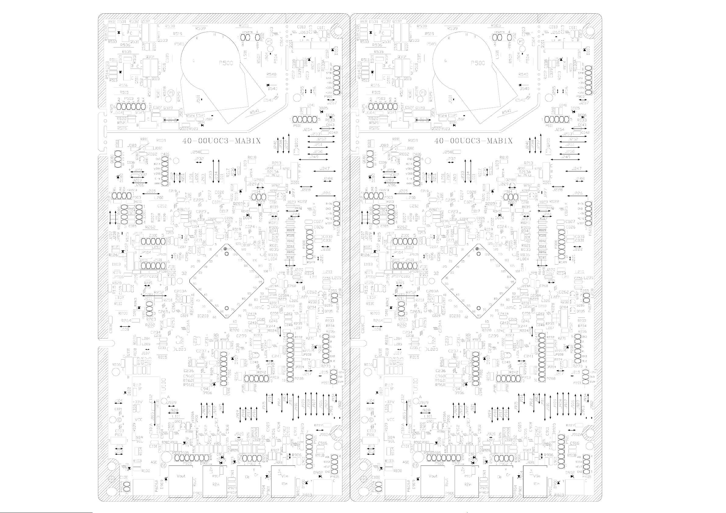
Page 49

 Loading...