

`
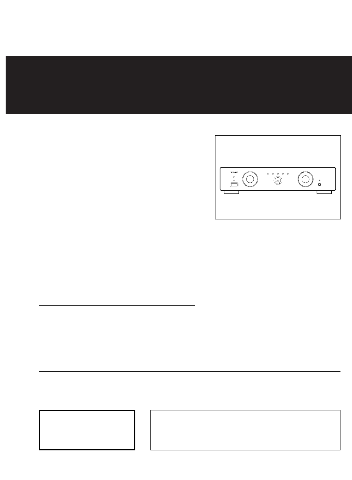
a-bx10mk™
Integrated Stereo Amplifier
Thanks for buying a TEAC. Read this manual carefully to get the best
performance from this unit.
Nous vous remercions pour l’achat d’un appareil TEAC.
Lire ce manuel avec attention pour obtenir les meilleures performances
possibles de cet appareil.
9A07108800
Vielen Dank für den Kauf dieses TEAC-Geräts.
Bitte lesen Sie diese Anleitung sorgfältig durch, um die Leistungsfähigkeit
dieses Geräts optimal nutzen zu können.
Grazie per aver acquistato un prodotto TEAC.
Leggere attentamente questo manuale per ottenere le migliori prestazioni
da questo apparecchio.
Enhorabuena por la adquisición de un TEAC.
Lea detenidamente este manual a fin de obtener el mejor rendimiento de
esta unidad.
Dank u voor de aanschaf van een TEAC.
Lees deze gebruiksaanwijzing aandachtig door teneinde de beste prestaties
van dit toestel te verkrijgen.
CAUTION: TO REDUCE THE RISK OF ELECTRIC SHOCK, DO NOT REMOVE COVER
(OR BACK). NO USER-SERVICEABLE PARTS INSIDE. REFER SERVICING TO QUALIFIED
Ü
The lightning flash with arrowhead symbol, within an equilateral triangle, is intended to alert
the user to the presence of uninsulated “dangerous voltage” within the product’s enclosure
ÿ
that may be of sufficient magnitude to constitute a risk of electric shock to persons.
SERVICE PERSONNEL.
OWNER’S MANUAL ..................................3
MANUEL DU PROPRIETAIRE...................6
BEDIENUNGSANLEITUNG........................9
MANUALE DI ISTRUZIONI .....................12
MANUAL DEL USUARIO ........................15
GEBRUIKSAANWIJZING.........................18
The exclamation point within an equilateral triangle is intended to alert the user to the presence of important
operating and maintenance (servicing) instructions in the literature accompanying the appliance.
Ÿ
This appliance has a serial number located
on the rear panel. Please record the model
number and serial number and retain them
for your records.
Model number
Serial number
WARNING: TO PREVENT FIRE OR SHOCK
HAZARD, DO NOT EXPOSE THIS
APPLIANCE TO RAIN OR MOISTURE.

– 2 –
IMPORTANT SAFETY INSTRUCTIONS
CAUTION:
O Read all of these Instructions.
O Save these Instructions for later use.
O Follow all Warnings and Instructions marked on the audio
equipment.
1) Read Instructions — All the safety and operating instructions should
be read before the product is operated.
2) Retain Instructions — The safety and operating instructions should
be retained for future reference.
3) Heed Warnings — All warnings on the product and in the operating
instructions should be adhered to.
4) Follow Instructions — All operating and use instructions should be
followed.
5) Cleaning — Unplug this product from the wall outlet before cleaning.
Do not use liquid cleaners or aerosol cleaners. Use a damp cloth for
cleaning.
6) Attachments — Do not use attachments not recommended by the
product manufacturer as they may cause hazards.
7) Water and Moisture — Do not use this product near water _for
example, near a bath tub, wash bowl, kitchen sink, or laundry tub; in a
wet basement; or near a swimming pool; and the like.
8) Accessories — Do not place this product on an unstable cart, stand,
tripod, bracket, or table. The product may fall, causing serious injury to a
child or adult, and serious damage to the product. Use only with a cart,
stand, tripod, bracket, or table recommended by the manufacturer, or
sold with the product. Any mounting of the product should follow the
manufacturer’s instructions, and should use a mounting accessory
recommended by the manufacturer.
9) A product and cart combination should be moved with care. Quick
stops, excessive force, and uneven surfaces may cause the product and
cart combination to overturn.
10) Ventilation — Slots and openings in the cabinet are provided for
ventilation and to ensure reliable operation of the product and to protect
it from overheating, and these openings must not be blocked or covered.
The openings should never be blocked by placing the product on a bed,
sofa, rug, or other similar surface. This product should not be placed in a
built-in installation such as a bookcase or rack unless proper ventilation
is provided or the manufacturer’s instructions have been adhered to.
11) Power Sources — This product should be operated only from the
type of power source indicated on the marking label. If you are not sure
of the type of power supply to your home, consult your product dealer or
local power company. For products intended to operate from battery
power, or other sources, refer to the operating instructions.
12) Grounding or Polarization — This product may be equipped with a
polarized alternating-current line plug (a plug having one blade wider
than the other). This plug will fit into the power outlet only one way. This
is a safety feature. If you are unable to insert the plug fully into the outlet,
try reversing the plug. If the plug should still fail to fit, contact your
electrician to replace your obsolete outlet. Do not defeat the safety
purpose of the polarized plug.
13) Power-Cord Protection — Power-supply cords should be routed so
that they are not likely to be walked on or pinched by items placed upon
or against them, paying particular attention to cords at plugs,
convenience receptacles, and the point where they exit from the product.
14) Outdoor Antenna Grounding — If an outside antenna or cable
system is connected to the product, be sure the antenna or cable system
is grounded so as to provide some protection against voltage surges and
built-up static charges. Article 810 of the National Electrical Code,
ANSI/NFPA 70, provides information with regard to proper grounding of
the mast and supporting structure, grounding of the lead-in wire to an
antenna discharge unit, size of grounding conductors, location of
antenna-discharge unit, connection to grounding electrodes, and
requirements for the grounding electrode.
"Note to CATV system installer:
This reminder is provided to call the CATV system installer’s attention to
Section 820-40 of the NEC which provides guidelines for proper
grounding and, in particular, specifies that the cable ground shall be
connected to the grounding system of the building, as close to the point
of cable entry as practical.
15) Lightning — For added protection for this product during a lightning
storm, or when it is left unattended and unused for long periods of time,
unplug it from the wall outlet and disconnect the antenna or cable
system. This will prevent damage to the product due to lightning and
power-line surges.
16) Power Lines — An outside antenna system should not be located in
the vicinity of overhead power lines or other electric light or power
circuits, or where it can fall into such power lines or circuits. When
installing an outside antenna system, extreme care should be taken to
keep from touching such power lines or circuits as contact with them
might be fatal.
17) Overloading — Do not overload wall outlets, extension cords, or
integral convenience receptacles as this can result in risk of fire or
electric shock.
18) Object and Liquid Entry — Never push objects of any kind into this
product through openings as they may touch dangerous voltage points
or short-out parts that could result in a fire or electric shock. Never spill
liquid of any kind on the product.
19) Servicing — Do not attempt to service this product yourself as
opening or removing covers may expose you to dangerous voltage or
other hazards. Refer all servicing to qualified service personnel.
20) Damage Requiring Service — Unplug this product from the wall
outlet and refer servicing to qualified service personnel under the
following conditions:
a) when the power-supply cord or plug is damaged.
b) if liquid has been spilled, or objects have fallen into the product.
c) if the product has been exposed to rain or water.
d) if the product does not operate normally by following the operating
instructions. Adjust only those controls that are covered by the operating
instructions as an improper adjustment of other controls may result in
damage and will often require extensive work by a qualified technician to
restore the product to its normal operation.
e) if the product has been dropped or damaged in any way.
f ) when the product exhibits a distinct change in performance _ this
indicates a need for service.
21) Replacement Parts — When replacement parts are required, be
sure the service technician has used replacement parts specified by the
manufacturer or have the same characteristics as the original part.
Unauthorized substitutions may result in fire, electric shock, or other
hazards.
22) Safety Check — Upon completion of any service or repairs to this
product, ask the service technician to perform safety checks to
determine that the product is in proper operating condition.
23) Wall or Ceiling Mounting — The product should be mounted to a
wall or ceiling only as recommended by the manufacturer.
24) Heat — The product should be situated away from heat sources
such as radiators, heat registers, stoves, or other products (including
amplifiers) that produce heat.
Example of Antenna Grounding as per
National Electrical Code, ANSI/NFPA 70
ANTENNA
LEAD IN
WIRE
GROUND
CLAMP
ANTENNA
DISCHARGE UNIT
(NEC SECTION 810-20)
ELECTRIC
SERVICE
EQUIPMENT
NEC - NATIONAL ELECTRICAL CODE
GROUNDING CONDUCTORS
(NEC SECTION 810-21)
GROUND CLAMPS
POWER SERVICE GROUNDING
ELECTRODE SYSTEM
(NEC ART 250. PART H)

Before Use
Main fuse
Spare fuse
IMPORTANT (for U.K. Customers)
DO NOT cut off the mains plug from this
equipment. If the plug fitted is not
suitable for the power points in your
home or the cable is too short to reach
a power point, then obtain an
appropriate safety approved extension
lead or consult your dealer.
If nonetheless the mains plug is cut off,
remove the fuse and dispose of the
plug immediately, to avoid a possible
shock hazard by inadvertent
connection to the mains supply.
If this product is not provided with a
mains plug, or one has to be fitted,
follow the instructions given below:
IMPORTANT. The wires in this mains
lead are coloured in accordance with
the following code:
GREEN-AND-YELLOW: EARTH
BLUE: NEUTRAL
BROWN: LIVE
WARNING: This apparatus must be
earthed.
As the colours of the wires in the mains
lead of this apparatus may not
correspond with the coloured markings
identifying the terminals in your plug
proceed as follows.
The wire which is coloured GREENand-YELLOW must be connected to the
terminal in the plug which is marked by
the letter E or by the safety earth
symbol © or coloured GREEN or
GREEN-and-YELLOW.
The wire which is coloured BLUE must
be connected to the terminal which is
marked with the letter N or coloured
BLACK.
The wire which is coloured BROWN
must be connected to the terminal
which is marked with the letter L or
coloured RED.
When replacing the fuse only a
correctly rated approved type should
be used and be sure to re-fit the fuse
cover.
IF IN DOUBT — CONSULT A
COMPETENT ELECTRICIAN.
then
Read This Before Operating
● Place the amplifier on a hard flat
surface.
● The ventilation holes should not be
covered. Make sure there is at least 20
cm (8 inches) of space above and at
least 5 cm (2 inches) of space besides
the amplifier. Do not place CD player or
other equipment on top of the amplifier.
● Avoid placing it in direct sunlight or
close to a source of heat. Also avoid
locations subject to vibrations and
excessive dust, heat, cold or moisture.
● Do not open the cabinet, as this might
result in circuitry damage or electrical
shock.
● When removing the power plug from the
wall outlet, always pull directly on the
plug; never yank the cord.
● Do not attempt to clean the unit with
chemical solvents, as this might damage
the finish. Use a clean, dry cloth.
● Keep this manual in a safe place for
future reference.
Notes on Power Sources
● Plug the AC power cord into an AC wall
receptacle. The correct voltage for
operating your unit is printed on the rear
panel.
∑ Main POWER Switch
● The main POWER switch is located on
the rear of the unit.
Press the ON side of this rocker (seesaw)
switch to turn power ON (standby position);
press the OFF side to turn power off.
Whenever the power is ON, the indicator on
the front panel glows red.
Note: Leave this main power switch ON at
all times.
∑ AC IN Socket
Plug the provided AC power cord into this
socket.
∑ Fuse Holder
After replacing fuses, be sure to close the
fuse compartment until it clicks.
Remote Control Unit
When operating the remote control unit,
point it towards the remote sensor on the
front panel of the unit.
∑ Battery Installation
1. Remove the battery compartment
cover.
2. Insert two “AAA” (R03, UM-4) dry
batteries.
Make sure that the batteries are
inserted with their positive ± and
negative — poles positioned correctly.
3. Close the cover until it clicks.
Battery Replacement.
If you notice that the distance between
the remote control unit and the player for
correct operation becomes shorter, it
indicates that the batteries are exhausted. In this case replace the batteries with
new ones.
Precautions concerning batteries
… Be sure to insert the batteries with
correct positive ± and negative —
polarities.
… Use batteries of the same type. Never
use different types of batteries
together.
… Rechargeable and non-rechargeable
batteries can be used. Refer to the
precautions on their labels.
… When the remote control unit is not to
be used for a long time (more than a
month), remove the batteries from the
remote control unit to prevent them
from leaking. If they leak, wipe away
the liquid inside the battery
compartment and replace the batteries
with new ones.
… Do not heat or disassemble batteries
and never dispose of old batteries by
throwing them in fire.
– 3 –
– 4 –
Front Panel
Front Panel
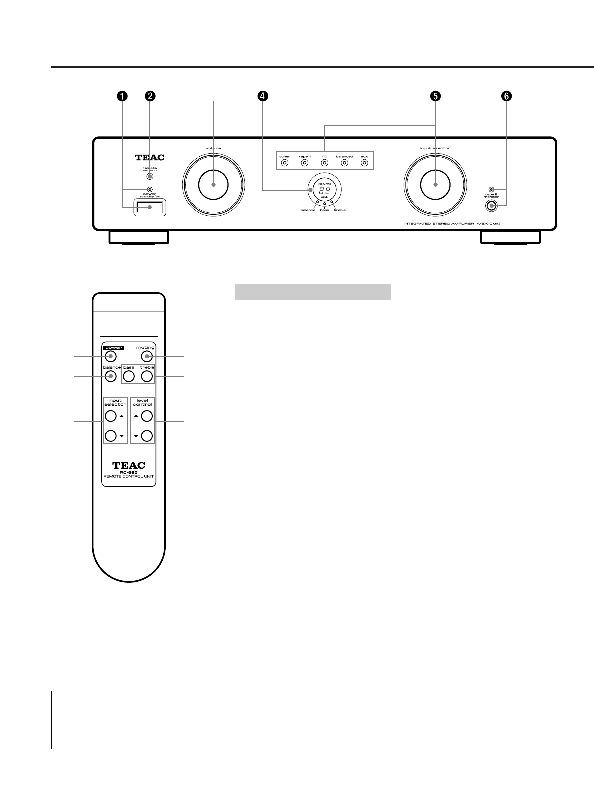
1 power switch
When the main power switch on the rear
panel is ON:
Turn the front power switch to ON.
Turn it again to the Standby Position to
switch power OFF, and the LED indicator
glows red.
2 remote sensor
3 volume control
This control is used to adjust signal output
levels to the speakers.
Use the level control (˙/¥) buttons to
adjust the volume. The volume can be
adjusted in 1 dB units from 0 dB (minimum)
to 79 dB (maximum).
4 volume level display
The current level setting is shown on the
display.
5 input selector & indicators
Turn the selector to choose the input
source to be played (tuner, tape 1, CD,
balanced, and aux).
The input source indicator will light.
6 tape 2 monitor switch & indicator
source:For reproduction of sound
from a source selected using the
input selector. The LED indicator
will not light.
tape: For reproduction of sound using
tape 2 monitor. The LED indicator
will light.
Phono Play
The PA-B10 plug-in "balanced MM/MC
preamplifier" board is optionally
available so you can connect a
turntable to this unit.
Certain buttons on the remote control unit
and on the front panel of the amplifier have
the same or similar functions and have the
same reference numbers.
● The power is turned on/off (standby) by
pressing the power button on the
remote control unit in standby mode.
7 muting button
(on the remote control unit)
Press this to mute (0 dB) the sound from the
speakers when answering the telephone,
etc. To restore the original volume, press
the input selector buttons or level control
(˙/¥) buttons. While muting is engaged,
the volume level display shows 0 dB.
8 balance control button
This button is used for adjusting the
balance of the volume level between the
left and right channels.
Press the balance button (the balance LED
indicator will light.), then press the level
control (˙/¥) buttons.
The level setting is shown on the display.
The balance level can be adjusted in 1 dB
units from – 6 dB to 6 dB.
9 Tone (bass/treble) controls
These two tone controls – bass and treble –
can be used to obtain a "flat" frequency
response or a tone which suits your
individual listening preference. The bass
control adjusts low frequencies and the
treble control adjusts the high frequencies.
Press the bass (or treble) button (the bass
or treble LED indicator will light.), then
press the level control (˙/¥) buttons.
It is possible to adjust the bass ( or treble)
two steps down (–1 or –2) or two steps up
(1 or 2).
● If levels are not adjusted within 10
seconds, the LED indicator will turn off,
and volume can be adjusted again.
Features and Controls
Remote Control Unit
3
1
7
89
5
3
0
ey
q
0
w
rt
Rear Panel
*Turn off all components before making connections.
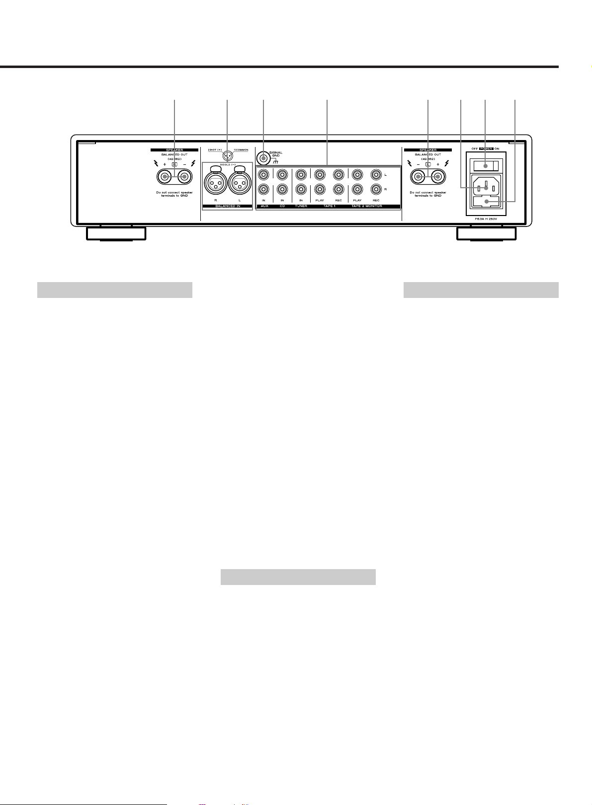
Rear Panel
0Speaker Terminals
Connect left loudspeaker to "SPEAKER L",
and right loudspeaker to "SPEAKER R".
Be sure that the loudspeakers are
connected in phase.
Caution: Short-circuiting of either of the
loudspeaker terminals to the cabinet,
ground or signal cables can damage the
amplifier. Short-circuit between the
loudspeaker terminals will blow the fuses.
Always turn off the amplifier when
connecting or disconnecting loudspeaker
cables or signal cables.
Caution: The loudspeaker output is
balanced. Do not connect any equipment
with unbalanced input (e.g. spectrum
analyzers and some electrostatic
loudspeakers).
q Balanced Input Connector
The balanced input is connected with XLR
plugs in accordance with IEC
specifications.
PIN 1: GND
PIN 2: +
PIN 3: –
w GND Terminal
Connect the ground lead of the turntable to
this terminal.
e Audio Signal Jacks
● AUX Input Jacks
Connect the audio output jacks of the
VCR to these jacks.
●
CD Input Jacks
Connect the output (LINE OUT) jacks of
the CD player to these jacks.
●
TUNER Input Jacks
Connect the output jacks of the tuner to
these jacks.
●
TAPE 1 PLAY/REC Jacks
Connect the output (LINE OUT) jacks of
the tape deck to the PLAY jacks and
connect the input (LINE IN) jacks of the
deck to the REC jacks.
●
TAPE 2 MONITOR PLAY/REC Jacks
These jacks are used for connection of a
second tape deck. Connect the output
(LINE OUT) jacks of the tape deck to the
PLAY jacks and connect the input (LINE
IN) jacks of the deck to the REC jacks.
r AC IN Socket (See page 3.)
t Main POWER Switch (See page 3.)
Press the ON side of this rocker (seesaw)
switch to turn power ON (standby position).
Note: Leave this main power switch ON at
all times.
y Fuse Holder (See page 3.)
Tape Dubbing
You can dub from the deck connected to
TAPE 1 jacks to the deck connected to TAPE
2 jacks. Dubbing from TAPE 2 deck to TAPE
1 deck is not possible.
1. Set the playback deck (TAPE 1) to the
playback mode, and the recording deck
(TAPE 2 MONITOR) to the record mode.
Adjust recording level accordingly.
(Refer to the owner's manuals of the
decks.)
2. Set the input selector to the tape 1
position and set the tape 2 monitor
switch to source.
Specifications
Continuous Power Output (RMS):
100W + 100W
(20 - 20,000 Hz, 8 ohms)
160W + 160W
(20 - 20,000 Hz, 4 ohms)
Dynamic Power Output (EIA):
120W + 120W (8 ohms)
220W + 220W (4 ohms)
Total Harmonic Distortion:
(Continuous rated output power)
0.04% (20 - 20,000 Hz, – 6dB, 8 ohms)
0.06% (20 - 20,000 Hz, – 6dB, 4 ohms)
Input Sensitivity/Impedance:
CD, TUNER, AUX, TAPE;
300 mV/ 20 k ohms
BALANCED (XLR); 600mV/10 k ohms
Output Level/Impedance:
TAPE 1, TAPE 2; 300 mV/100 ohms
Signal-to-Noise Ratio (IHF-A):
CD, TUNER,AUX, TAPE;104 dBA
Frequency Response:
CD, TUNER, AUX, TAPE, BALANCED;
20 - 20,000 Hz, +0 /–0.8 dB
Power Requirements/Power Consumption:
120 V AC, 60 Hz, 5 A (U.S.A./Canada
Model/General Export Model)
220 V AC, 50/60 Hz, 500 W (Korea)
230 V AC, 50 Hz, 500 W (Europe/ UK/
General Export Model)
Dimensions (W x H x D):
442 x 103 x 383 mm
Weight (net): 12.0 kg
Standard Accessories:
Remote Control Unit (RC-685) x 1,
AC cord x 1
Improvements may result in features and
specifications being changed without
notice.
– 5 –

– 6 –
Avant utilisation
Bien lire ceci avant utilisation
● Placer l'amplificateur sur une surface
plate rigide.
● Les trous de ventilation ne doivent pas
être couverts. S'assurer qu'il y a un
espace d'au moins 20 cm au dessus et
d'au moins 5 cm à côté de
l'amplificateur. Ne pas placer un lecteur
CD ou un autre appareil sur le dessus de
l'amplificateur.
● Eviter de le placer directement au soleil
ou près d'une source de chaleur. Eviter
également les endroits sujets aux
vibrations, et à la poussière, la chaleur,
le froid ou l'humidité.
● Ne pas ouvrir le coffret, il pourrait en
résulter un dommage de l'électronique
ou des chocs électriques.
● Pour débrancher la fiche d'alimentation
de la prise secteur, toujours tirer
directement sur la fiche; ne jamais
arracher le cordon.
● Ne pas essayer de nettoyer l'appareil
avec des solvants chimiques, ils
pourraient endommager le fini. Utiliser
un chiffon sec et propre.
● Conserver ce manuel dans un endroit
sûr pour une référence ultérieure.
Remarques sur les sources
d'alimentation
● Brancher ce cordon d'alimentation
secteur à une prise secteur CA. La
tension correcte pour le fonctionnement
de votre appareil est imprimée sur le
panneau arrière.
∑ Interrupteur principal d'alimenta-
tion POWER
● L’interrupteur principal d’alimentation
est situé sur I’arrière de I’appareil.
Appuyer sur le côté ON de ce commutateur à bascule pour mettre
l'alimentation sur marche (position
d'attente); appuyer sur le côté OFF pour
couper l'alimentation. Quand l'alimentation
est fournie, l'indicateur sur le panneau
avant s'allume en rouge.
Remarque: Toujours laisser cet interrupteur principal d'alimentation sur ON.
∑ Prise d'entrée secteur
Brancher le cordon d'alimentation secteur
fourni dans cette prise.
∑ Porte-fusible
Après remplacement des fusibles,
s'assurer de refermer le compartiment
fusible jusqu'à son déclic.
Fusible principal
Fusible
de rechange
Pour utiliser la télécommande, la pointer
vers le capteur de télécommande du
panneau avant de l'appareil.
∑ Mise en place des piles
1. Retirer le couvercle du compartiment
des piles.
2. Introduire deux piles "AAA" (R03, UM-4).
S'assurer que les piles sont installées
correctement en respectant la polarité
plus ± et moins —.
3. Fermer le couvercle jusqu'à son déclic.
Remplacement des piles
Si vous remarquez que la distance entre la
télécommande et le lecteur devient plus
courte pour assurer un fonctionnement
correct, ceci indique que les piles sont
usées. Dans ce cas, remplacer les piles par
des neuves.
Précautions à observer concernant les
piles
O Bien placer les piles en respectant la
polarité plus (+) et moins (–).
O Utiliser des piles du même type. Ne
jamais utiliser ensemble différents types
de piles.
O Des piles ou des batteries peuvent être
utilisées. Se référer aux précautions à
observer sur leurs étiquettes.
O Si la télécommande n'est pas utilisée
pendant une longue période (plus d'un
mois), retirer les piles de la
télécommande pour éviter des fuites
des piles. Si elles coulent, bien essuyer
le liquide dans le compartiment des
piles et remplacer les piles par des
neuves.
O Ne pas chauffer, ni démonter les piles et
ne jamais les mettre au feu.
Télécommande

3
3
5
7
89
1
Caractéristiques et commandes
Panneau avant
Boîtier de télécommande
Panneau avant
1 Interrupteur d'alimentation
Lorsque l'interrupteur principal
d'alimentation POWER sur le panneau
arrière est sur ON:
Mettre l'interrupteur d'alimentation avant
sur ON.
Le remettre en position d'attente pour
couper l'alimentation, et l'indicateur à LED
passe en rouge.
2 Détecteur du signal de
télécommande (remote sensor)
3 Commande de volume
Cette commande est utilisée pour régler le
niveau des signaux sortis vers les
enceintes acoustiques.
Utiliser les touches de commande de
niveau (˙/¥) pour ajuster le volume. Le
volume peut être ajusté par pas de 1 dB de
0 dB (minimum) à 79 dB (maximum).
4 Affichage du niveau de volume
Le réglage du niveau courant est montré
sur l’affichage.
Certaines touches sur la télécommande et
sur le panneau avant de l’amplificateur ont
les mêmes ou des fonctions similaires et
ont les mêmes numéros de référence.
● L’alimentation est mise/coupée (attente)
en appuyant sur la touche power sur la
télécommande en mode d’attente.
Lecture phono
La platine préamplificateur infichable
PA-B10 ("balanced MM/MC
preamplifier") est disponible en option
pour vous permettre de raccorder une
platine tourne-disque à cet appareil.
5 Sélecteur d'entrée (input selector)
et indicateurs
Tourner le sélecteur pour choisir la source
d'entrée à lire (syntoniseur, bande 1, CD,
symétrique ou Aux). L’indicateur de la
source d’entrée s’allumera.
6 Commutateur de moniteur bande 2
(tape 2 monitor) et indicateur
source:Pour la reproduction du son d'une
tape: Pour la reproduction du son en
source sélectionnée en utilisant le
sélecteur d'entrée. L’indicateur LED
ne s’allumera pas.
utilisant le moniteur bande 2.
L’indicateur LED s’allumera.
7 Touche muting
(sur la télécommande)
La presser pour rendre silencieux (0 dB) le
son des haut-parleurs, pour répondre au
téléphone, etc. Pour revenir au volume
original, appuyer sur les touches du
sélecteur d’entrée ou sur les touches de
commande de niveau (˙/¥). Alors que le
silencieux est engagé, l’affichage du
niveau sonore montre 0 dB.
8 Touche de contrôle de la balance
Cette touche permet d’équilibrer le niveau
sonore entre les canaux droit et gauche.
Appuyer sur la touche de balance
(l’indicateur LED de la balance s’allumera.),
puis appuyer sur les touches de commande
de niveau (˙/¥).
Le réglage du niveau est montré sur
l’affichage.
Le niveau de la balance peut être réglé par
pas de 1 dB de – 6 dB à 6 dB.
9 Commandes de tonalité
(Tone (bass/treble))
Ces deux commandes de tonalité – bass et
treble – peuvent être utilisées pour obtenir
une réponse en fréquence "plate" ou une
tonalité qui répond à vos goûts personnels
d'écoute. La commande bass ajuste les
fréquences basses et treble, les
fréquences élevées. Appuyer sur la touche
bass (ou treble) (l’indicateur LED bass ou
treble s’allumera.), puis appuyer sur les
touches de commande de niveau (˙/¥).
Il est possible d’ajuster les graves (ou les
aigus) de deux pas plus bas (– 1 ou – 2) ou
de deux pas plus haut (1 ou 2).
● Si les niveaux ne sont pas ajustés dans
les 10 secondes, l’indicateur LED
s’éteindra, et le volume peut être ajusté
de nouveau.
– 7 –

Caractéristiques et commandes
– 8 –
Panneau arrière
0Bornes de haut-parleurs
Raccorder l'enceinte acoustique gauche à
"SPEAKER L" et l'enceinte droite à
"SPEAKER R". S'assurer que les enceintes
sont bien branchées en phase.
Attention: Faire un court-circuit des bornes
de haut-parleurs au niveau du coffret, de la
masse ou des câbles de signal peut
endommager l'amplificateur. Un courtcircuit entre les bornes de haut-parleurs
fera griller les fusibles. Toujours couper
l'alimentation de l'amplificateur en
branchant ou débranchant des câbles de
haut-parleur ou des câbles de signal.
Attention: La sortie des haut-parleurs est
symétrique. Ne pas raccorder d'appareil
avec entrée asymétrique (par exemple des
analyseurs de spectre et certains hautparleurs électrostatiques).
q Connecteur d'entrée symétrique
L'entrée symétrique est raccordée avec
des fiches XLR selon les spécifications IEC.
Broche 1: Masse (GND)
Broche 2: + (point chaud)
Broche 3: – (point froid)
w Borne de masse (GND)
Raccorder le fil de masse de la platine
tourne-disque à cette borne.
e Prises des signaux audio
● Prises d'entrée AUX
Raccorder les prises de sortie audio du
magnétoscope à ces prises.
●
Prises d'entrée CD
Raccorder les prises de sortie (LINE
OUT) du lecteur à ces prises.
●
Prises d'entrée TUNER
Raccorder les prises de sortie du
syntoniseur à ces prises.
●
Prises TAPE 1 PLAY/REC
Raccorder les prises de sortie (LINE
OUT) de la platine à cassette aux prises
PLAY et raccorder les prises d'entrée
(LINE IN) de la platine aux prises REC.
●
Prises TAPE 2 MONITOR PLAY/REC
Ces prises sont utilisées pour le
raccordement d'une seconde platine à
cassette. Raccorder les prises de sortie
(LINE OUT) de la platine à cassette aux
prises PLAY et raccorder les prises
d'entrée (LINE IN) de la platine aux
prises REC.
r Prise d'entrée secteur (voir page 6.)
t Interrupteur principal d'alimenta-
tion POWER (voir page 6.)
Appuyer sur le côté ON de ce commutateur à bascule pour mettre
l'alimentation sur marche (position
d'attente).
Remarque: Toujours laisser cet interrupteur principal d'alimentation sur ON.
y Porte-fusible (voir page 6.)
Copie de bande
Vous pouvez copier de la platine raccordée
aux prises TAPE 1 vers la platine raccordée
aux prises TAPE 2. La copie de la platine
TAPE 2 vers la platine TAPE 1 n'est pas
possible.
1. Régler la platine de lecture (TAPE 1) en
mode de lecture, et la platine
d'enregistrement (TAPE 2 MONITOR) en
mode d'enregistrement. Régler
correctement le niveau d'enregistrement. (Se reporter aux manuels
d'instructions des platines.)
2. Régler le sélecteur d'entrée sur la
position tape 1 et régler le commutateur de moniteur bande 2 sur
source.
Caractéristiques techniques
Puissance de sortie continue (RMS):
100 W + 100 W
(20 à 20.000 Hz, 8 ohms)
160 W + 160 W
(20 à 20.000 Hz, 4 ohms)
Puissance de sortie dynamique (EIA):
120 W + 120 W (8 ohms)
220 W + 220 W (4 ohms)
Distorsion harmonique totale:
(puissance de sortie nominale
continue)
0,04%
(20 à 20.000 Hz, –6 dB, 8 ohms)
0,06%
(20 à 20.000 Hz, –6 dB, 4 ohms)
Sensibilité d'entrée/impédance:
CD, TUNER, AUX, TAPE;
300 mV/20 k ohms
BALANCED (XLR); 600mV/10 k ohms
Niveau de sortie/impédance:
TAPE 1, TAPE 2; 300 mV/100 ohms
Rapport signal sur bruit (IHF-A):
CD, TUNER, AUX, TAPE; 104 dBA
Réponse en fréquence:
CD, TUNER, AUX, TAPE, BALANCED;
20 à 20.000 Hz, +0 /– 0,8 dB
Alimentation/consommation:
120 V CA, 60 Hz, 5 A (Modèle EtatsUnis/Canada/Modèle exportation
générale)
220 V CA, 50/60 Hz, 500 W (Corée)
230 V CA, 50 Hz, 500 W (Modèle
Europe / Royaume-Uni /Modèle
exportation générale)
Dimensions (L x H x P): 442 x 103 x 383 mm
Poids (net): 12,0 kg
Accessoires standard:
Télécommande (RC-685) x 1,
Cordon d'alimentation secteur x 1
Des améliorations peuvent apporter des
modifications dans les caractéristiques
techniques et générales sans préavis.
Panneau arrière
*Couper I’alimentation de tous les appareils avant de faire des raccordements.
0
q
w
ey
0
rt

Vor Inbetriebnahme
Bitte vor Ingebrauchnahme
durchlesen
● Den Verstärker auf einer stabilen und
flachen Unterlage aufstellen.
● Auf einwandfreien Temperaturausgleich
achten. Die Ventilationsöffnungen
freihalten und über dem Verstärker
mindestens 20 cm, neben dem
Verstärker mindestens 5 cm Abstand
einhalten. Keine anderen Geräte (CDPlayer etc.) auf dem Verstärker
plazieren!
● Aufstellpositionen vermeiden, an denen
hohe Temperaturen (direkte Sonneneinstrahlung, Heizkörper etc.), Vibrationen,
zu hohe Staubeinwirkung, zu niedrige
Temperaturen oder Feuchtigkeit auftreten können.
● Niemals das Gehäuse öffnen.
Andernfalls können Schaltkreise
beschädigt werden und es besteht
Stromschlaggefahr!
● Das Netzkabel beim Abziehen von der
Steckdose stets am Stecker halten.
Niemals mit Gewalt am Kabel ziehen!
● Zur Gehäusereinigung niemals
Lösungsmittel verwenden. Andernfalls
kann die Gehäuseoberfläche beschädigt
werden. Mit einem weichen trockenen
Tuch reinigen.
● Bewahren Sie diese Anleitung zur
späteren Bezugnahme sorgfältig auf.
Hinweise zur Spannungsversorgung
● Vor Anschluß an einer Netzsteckdose
sicherstellen, daß die zulässige Voltzahl
(angezeigt an der Geräterückseite)
anliegt.
∑ Netz-Hauptschalter (POWER)
● Der Hauptnetzschalter (POWER)
befindet sich an der Geräterückseite.
Zur Einschaltung der Betriebsbereitschaft
diesen Wippschalter im Abschnitt ON
drücken. Zur Abschaltung den Abschnitt
OFF drücken. Bei Betriebsbereitschaft (ON)
leuchtet die LED-Anzeige an der
Gerätevorderseite rot.
Hinweis: Der Netz-Hauptschalter muß
stets auf ON gestellt sein.
∑ Netzeingang (AC IN)
Hier das mitgelieferte Netzkabel
anschließen.
∑ Sicherungsfach
Nach jedem Sicherungswechsel sicherstellen, daß das Sicherungsfach bis zum
Anschlag geschlossen ist.
Hauptsicherung
Ersatzsicherung
Fernbedieneinheit
Die Fernbedieneinheit bei Gebrauch auf
den Fernbediensensor am Deck ausrichten.
∑ Einlegen der Batterien
1. Die Batteriefach-Abdeckung entfernen.
2. Zwei Batterien "AAA" (R03, UM-4)
polrichtig (≠/–) einlegen.
3. Die Abdeckung wieder einwandfrei
anbringen.
Batteriewechsel
Muß der Abstand zwischen Gerät und
Fernbedieneinheit zur Funktionsauslösung
verringert werden, wird ein
Batteriewechsel notwendig. Stets zwei
neue Batterien einlegen.
Batterie-Vorsichtsmaßregeln
O Die Batterien stets polrichtig (
einlegen.
O Stets zwei Batterien der gleichen Aus-
führung verwenden. Niemals gleichzeitig eine gebrauchte und eine neue
Batterie verwenden.
O Sowohl Einweg- als auch wiederauf-
ladbare Batterien sind verwendbar. Die
Sicherheitshinweise auf den Batterien
beachten.
O Bei längerem Nichtgebrauch (über
einen Monat) sollten die Batterien
entnommen werden, um dem Auslaufen
der Batterien vorzubeugen.
Ausgelaufene Batterien entnehmen
und nach Säubern des Batteriefachs
gegen frische auswechseln.
O Batterien niemals erhitzen, zerlegen
oder zur Entsorgung verbrennen.
≠/–)
– 9 –

Besonderheiten und Bedienungselemente
– 10 –
3
Gerätevorderseite
Gerätevorderseite
1 Netzschalter (power)
Bei auf ON gestelltem Hauptschalter
(Geräterückseite):
Den Netzschalter in Position ON bringen.
Zur Abschaltung den Netzschalter in die
Position für Betriebsbereitschaft bringen.
Die LED-Anzeige leuchtet rot.
2 Fernbedien-Sensor
(remote sensor)
3 Lautstärkeregler (volume)
Für das Signal, das an die Lautsprecher
abgegeben wird.
Die Lautstärke mit den Pegeltasten (˙/¥)
einstellen. Der Einstellbereich wechselt in
1-dB-Schritten und reicht von 0 dB (min.)
bis 79 dB (max.).
4 Lautstärkeanzeige (volume)
Zeigt den gewählten Lautstärkepegel an.
5 Eingangswahlregler
(input selector) mit Anzeigen
Zur Anwahl der Signalquelle drehen (Tuner,
Band 1, CD, symmetrisch und Aux).
Die Anzeige der externen Signalquelle
leuchtet.
6 Monitor-Schalter (tape 2 monitor)
für Cassettendeck 2 mit Anzeige
source: Für Tonwiedergabe der mit dem
Eingangswahlregler gewählten
Signalquelle. Die LED-Anzeige
leuchtet nicht.
tape: Für Tonwiedergabe mit der
Monitorfunktion für Cassettendeck 2. Die LED-Anzeige leuchtet.
Einige Tasten der Fernbedienung und die
Tasten des Bedienungsfeldes des
Verstärkers weisen identische oder
ähnliche Funktionen auf. Daher besitzen Sie
auch die gleichen Referenznummern in
dieser Anleitung.
● Zur Geräteeinschaltung mit der
Fernbedieneinheit (Taste
power) muß das
Gerät auf Bereitschaft geschaltet sein.
7 Stummschalt-Taste (muting)
(auf Fernbedienung)
Während eines Telefongespräches, etc.
kann durch Betätigen dieser Taste die
Wiedergabe (Lautsprecher,) stummgeschaltet (0 dB) werden. Zur Rückstellung
auf die urspüngliche Lautstärke die
Eingangswahltasten oder Pegeltasten
(˙/¥) verwenden.
Bei Stummschaltung liegt die
Lautstärkeanzeige 0 dB vor.
8 Balancetaste (balance)
Mit dieser Taste bestimmen Sie das
Lautstärkeverhältnis des rechten und
linken Kanals zueinander.
Erst die Balancetaste (die Balance-LEDAnzeige leuchtet) und dann die Pegeltasten
(˙/¥) drücken.
Der eingestellte Pegel wird auf dem
Displayfeld angezeigt.
Der Balancepegel kann im Bereich von –6
dB bis 6 dB eingestellt werden.
9 Tiefen- und Höhenregler
(bass/treble)
Für eine Klangregelung nach Ihrem
Geschmack, mit linearem Frequenzgang
oder bei Betonung der niedrigen bzw.
hohen Frequenzen: bass-Regler für
niedrige Frequenzen, treble-Regler für hohe
Frequenzen. Erst die Tiefen- oder
Höhentaste (die Tiefen- oder Höhen-LEDAnzeige leuchtet) und dann die Pegeltasten
(˙/¥) drücken. Der Tiefen- oder
Höhenpegel kann in vier Stufen (–2 oder –1
und 1 oder 2) eingestellt werden.
● Erfolgt innerhalb von 10 Sekunden
keinerlei Pegeleinstellung, erlischt die
LED-Anzeige und es kann erneut der
Lautstärkepegel eingestellt werden.
Phono-Wiedergabe
Die als Sonderzubehör erhältliche
Vorverstärker-Steckplatine PA-B10
("balanced MM/MC preamplifier")
ermöglicht den Anschluß eines
Plattenspielers an diesem Verstärker.
Fernbedienung
1
7
89
5
3

0
ey
q
0wrt
Geräterückseite
*Vor dem Anschluß alle Geräte abschalten.
Geräterückseite
0 Lautsprecherklemmen
Den linken Lautsprecher an “SPEAKER L”,
den rechten Lautsprecher an “SPEAKER R”
anschließen. Auf phasenrichtigen
Anschluß achten.
Achtung: Bei Kurzschlußkontakten
zwischen Lautsprecherklemmen und
Gehäuse, Erdungs- oder Signalkabeln kann
die Endstufe beschädigt werden. Bei
Kurzschlußkontakten zwischen den
Lautsprecherklemmen brennen die
Sicherungen durch. Bei Anschluß der
Lautsprecher- und Signalkabel muß die
Verstärker-Netzspannung ausgeschaltet
sein!
Achtung: Symmetrische Lautsprecherausgänge. Niemals Geräte anschließen, die
einen unsymetrischen Eingang erfordern
(z.B. Spectrum Analyzer und einige
elektrostatische Lautsprecher).
q Symmetrischer Signaleingang
XLR-Buchse nach der IEC-Norm.
Pin 1: Erde
Pin 2: +
Pin 3: –
w Erdungskontakt
Hier das Massekabel des Plattenspielers
anschließen.
e Audio-Anschlüsse
● AUX-Eingang (AUX)
Mit dem Audio-Ausgang eines
Videorecorders verbinden.
●
CD-Eingang (CD)
Für die Anschlußverbindung mit dem
Line-Ausgang eines, CD-Players.
●
Tuner-Eingang (TUNER)
Mit dem Audio-Ausgang eines Tuners
verbinden.
●
Band-1-Eingang/Ausgang
(TAPE 1 PLAY/REC)
Den Line-Ausgang des Cassettendecks
mit den PLAY-Buchsen, den Line-Eingang
des Cassettendecks mit den RECBuchsen verbinden.
●
Band-2-Monitor-Eingang/Ausgang
(TAPE 2 MONITOR PLAY/REC)
Mit einem zweiten Cassettendeck
verbinden. Dessen Line-Ausgang mit den
PLAY-Buchsen, dessen Line-Eingang mit
den REC-Buchsen verbinden.
r Netzeingang (AC IN)
(Siehe Seite 9.)
t Netz - Hauptschalter (POWER)
(Siehe Seite 9.)
Zur Einschaltung der Betriebsbereitschaft
diesen Wippschalter im Abschnitt ON
(Bereitschaft) drücken.
Hinweis: Der Netz-Hauptschalter muß
stets auf ON gestellt sein.
y Sicherungsfach (Siehe Seite 9.)
Bandkopieren
Bandkopieren ist von Bandgerät 1 (TAPE 1Buchsen) auf Bandgerät 2 (TAPE 2
MONITOR Buchsen) möglich. Kopierbetrieb
in Gegenrichtung ist nicht möglich.
1. Das Wiedergabegerät (TAPE 1) auf
Wiedergabe schalten, das Aufnahmegerät (TAPE 2 MONITOR) auf Aufnahme
schalten. Den Aufnahmepegel wie
erforderlich aussteuern. (Siehe die
Bedienungsanleitung des Bandgeräts.)
2. Den Eingangswahlregler in die tape 1Position bringen. Den tape 2 monitorSchalter in Position source bringen.
Technische Daten
Ausgangsleistung (RMS):
100 W + 100 W (20 - 20.000 Hz, 8 Ohm)
160 W + 160 W (20 - 20.000 Hz, 4 Ohm)
Dynamikleistung (EIA):
120 W + 120 W (8 Ohm)
220 W + 220 W (4 Ohm)
Klirrfaktor: (bei Nenn-Ausgangsleistung)
0,04 % (20 - 20.000 Hz, – 6 dB, 8 Ohm )
0,06 % (20 - 20.000 Hz, – 6 dB, 4 Ohm )
Eingangsempfindlichkeit/Impedanz:
CD, TUNER, AUX, TAPE;
300 mV/20 kOhm
BALANCED (XLR): 600mV/10 kOhm
Ausgangspegel/Impedanz:
TAPE 1, TAPE 2; 300 mV/100 Ohm
Störspannungsabstand (IHF-A):
CD, TUNER, AUX, TAPE; 104 dBA
Frequenzgang:
CD, TUNER, AUX, TAPE, BALANCED;
20 - 20.000 Hz, +0 /– 0,8 dB
Spannungsversorgung/Leistungsaufnahme:
120 V Wechselspannung, 60 Hz, 5 A
(USA/Kanada/Allgemeines
Exportmodell)
220 V Wechselspannung, 50/60 Hz,
500 W (Korea)
230 V Wechselspannung, 50 Hz, 500 W
(Europa/Großbritannien/Allgemeines
Exportmodell)
Abmessungen (BxHxT): 442 x 103 x 383 mm
Gewicht (netto): 12,0kg
Standardzubehör:
Fernbedieneinheit (RC-685) x 1,
Netzkabel x 1
Verbesserungen bei Leistungsdaten und
Ausstattung vorbehalten.
– 11 –

Prima dell’uso
– 12 –
Leggere prima dell'uso
● Installare l'amplificatore su di una
superficie dura ed in piano.
● Le fessure di ventilazione non devono
venire coperte. Controllare che vi siano
almeno 20 cm di spazio sopra ed almeno
5 cm sui lati dell'amplificatore. Non
posare lettori CD o altri componenti
direttamente sull'amplificatore.
● Evitare di esporlo alla diretta luce del
sole o ad una sorgente di calore. Evitare
inoltre luoghi soggetti a vibrazioni o ad
eccessive accumulazioni di polvere,
calore, freddo od umidità.
● Non aprire la cassa dell'apparecchio.
Ciò potrebbe danneggiarne la
circuitazione o causare scariche
elettriche.
● Per staccare la spina dalla presa di rete,
agire direttamente sulla spina stessa,
evitando di tirare il cavo.
● Evitare di pulire l'apparecchio con
solventi chimici poichè ciò potrebbe
danneggiare la rifinitura esterna. Fare
semplicemente uso di un panno pulito ed
asciuto.
● Tenere questo manuale in un luogo di
facile accesso, per ogni eventuale futuro
riferimento.
Note sulla sorgente di
alimentazione
● Inserirlo in una presa di corrente
alternata di rete. Il corretto voltaggio
necessario per il funzionamento
dell'apparecchio è stampato sul
pannello posteriore.
∑ Interruttore di corrente principale
(POWER)
Premete il lato ON dell'interruttore per
accendere l'unità (posizione di attesa).
Premete il lato OFF per spegnerla. Se l'unità
è accesa, l'indicatore del pannello
anteriore diviene rosso.
Nota: Lasciace questo interruttore di
corrente principale su la posizione attivata
(ON).
∑ Presa AC IN
Collegare qui il cavo di alimentazione a
corrente alternata in dotazione.
∑ Portafusibili
Sostituiti i diffusori, spingere il coperchio
del vano fusibili sino a che non si chiude
con uno scatto.
Fusibile principale
Il telecomando deve essere usato
puntandolo verso il sensore del pannello
anteriore dell'apparecchio.
∑ Installazione delle batterie
1. Togliere il coperchio del vano delle
batterie.
2. Inserire due batterie "AAA" (o R03, o
UM-4).
Verificare che le batterie siano inserite
con i poli positivo ± e negativo — nelle
posizioni corrette.
3. Richiudere il coperchio sino a quando si
ode un leggero scatto.
Sostituzione delle batterie
Se la distanza utile di funzionamento del
telecomando risulta diminuire le batterie
sono probabilmente vicine all'esaurimento.
Provvedere alla loro sostituzione.
Precauzioni riguardanti le batterie
O Verificare che le batterie siano inserite
con le polarità ± e — nella posizione
corretta.
O Usare batterie dello stesso tipo. Non
usare mai assieme tipi diversi di
batterie.
O Possono essere usate sia batterie
ricaricabili che batterie non ricaricabili.
Vedere le indicazioni dell'etichetta.
O Se si prevede di non utilizzare il
telecomando per un lungo periodo (oltre
un mese), togliere le batterie per
prevenire possibili perdite. In caso di
perdite, pulire il vano batterie e
sostituire le batterie con altre nuove.
O Non riscaldare le batterie, non
smontarle e non gettarle nel fuoco.
Uso del telecomando
CONFORME AL D.M. 13 APRILE 1989
DIRETTIVA CEE/87/308
Fusibile di scorta

Caratteristiche e comandi
3
3
5
7
89
1
Pannello anteriore
Unità per il comando a distanza
Pannello anteriore
1 Interruttore di alimentazione
Quando l'interruttore di alimentazione del
pannello posteriore è su ON:
Portando su ON l'interruttore di
alimentazione del pannello anteriore.
Portandolo sulla posizione di attesa,
l'indicatore diviene rosso.
7 Tasto muting (sul telecomando)
Premere questo tasto per escludere (0 dB)
temporaneamente il suono dai diffusori
quando si deve rispondere al telefono, o in
altre situazioni analoghe. Per tornare al
volume iniziale, agire sui tasti di selezione
dell’ingresso o sui tasti di regolazione del
livello (˙/¥). In modalità di silenziamento,
il livello del volume visualizzato sul
quadrante è di 0 dB.
2 Sensore del telecomando
(remote sensor)
3 Comando del volume (volume)
Questo comando viene usato per regolare il
livello dei segnali in uscita verso i sistemi
degli altoparlanti.
Regolare il volume per mezzo dei tasti di
comando del livello (˙/¥). Il volume può
essere regolato a scatti di 1 dB da 0 dB
(minimo) a 79 dB (massimo).
4 Visualizzazione del livello del
volume (volume)
La predisposizione del livello del momento
viene visualizzata sul quadrante.
5 Selettore “input selector” e
Alcuni tasti del telecomando e sul pannello
frontale dell’amplificatore hanno funzioni
uguali o simili e sono perciò contraddistinti
dagli stessi numeri di riferimento.
● L'apparecchio, qualora in posizione di
attesa, può venire attivato o disattivato
(con apparecchio in attesa) agendo
sull'apposito tasto power del
telecomando.
indicazioni relative
Ruotare il selettore per selezionare la fonte
in ingresso per la riproduzione tra tuner,
tape 1, CD, balanced, ed aux.
L’indicazione della sorgente di ingresso si
illumina.
6 Commutatore “tape 2 monitor” e
indicazioni relative
source: Per la riproduzione di un suono da
tape: Per la riproduzione di segnale audio
Riproduzione di dischi analogici
La scheda di preamplificazione PA-B10
("balanced MM/MC preamplifier") è
disponibile opzionalmente in modo da
permettere il collegamento all'unità di
un giradischi.
una sorgente scelta con il selettore
d'ingresso. L’indicazione a diodi
luminosi (LED) non si illumina.
proveniente dal registratore tape
2. L’indicazione a diodi luminosi
(LED) si illumina.
– 13 –
8 Tasto del bilanciamento
“balance control”
Serve per regolare il bilanciamento del
volume tra i canali sinistro e destro.
Premere il tasto del bilanciamento (la
relativa indicazione LED si illumina) ed
agire poi opportunamente sui tasti di
regolazione del livello (˙/¥). Il livello
predisposto viene visualizzato sul
quadrante.
Il livello del bilanciamento può essere
regolato a scatti di 1 dB, da – 6 dB a + 6 dB.
9 Controlli del tono per bassi e acuti
(bass/treble)
Questi due comandi della tonalità, – bass e
treble – possono essere utilizzati per
ottenere una risposta in frequenza "piatta",
o una tonalità che si adegui alle proprie
preferenze individuali. Il comando bass
regola le frequenze basse, mentre quello
treble agisce sulle frequenze alte.
Premere il tasto “bass” (o “treble”, le
relative indicazioni LED si illuminano) ed
agire poi sui tasti di regolazione del livello
(˙/¥). I bassi (o gli acuti) possono essere
modificati di due gradi verso il basso
(–1 o –2) o verso l’alto (+1 o +2).
● Se i livelli non vengono regolati entro
dieci secondi dall’accensione
dell’indicazione LED, quest’ultima si
spegne, e si può nuovamente passare
alla regolazione del volume.

Caratteristiche e comandi
– 14 –
Pannello posteriore
0 Terminali dei diffusori
Collegare il diffusore sinistro a "SPEAKER L"
e quello destro a "SPEAKER R". Controllare
che i diffusori siano collegati in fase.
Attenzione: I corto circuiti dei terminali dei
diffusori, dei cavi di terra o dei cavi del
segnale possono danneggiare
l'amplificatore. I corto circuiti fra i terminali
dei diffusori fanno saltare un fusibile. Prima
di collegare o scollegare i cavi dei diffusori
o quelli del segnale, spegnere sempre il
sistema.
Attenzione: L'uscita dei diffusori è
bilanciata. Non collegarvi alcun
componente la cui uscita sia non bilanciata
(ad esempio analizzatori di spettro o
altoparlanti elettrostatici).
q Connettore d'ingresso bilanciato
L'ingresso bilanciato viene collegato con
spinotti XLR in accordo con le prescrizioni
IEC.
PIEDINO 1: TERRA
PIEDINO 2: +
PIEDINO 3: –
w Terminale per messa a terra (GND)
Collegare a questo terminale il cavo per la
messa a terra del giradischi.
e Prese del segnale audio
● Prese di ingresso AUX
Collegare le prese di uscita audio del
VCR a queste prese.
●
Prise di ingresso CD
Collegare a queste prese le prese (LINE
OUT) di uscita del lettore CD.
●
Prese di ingresso TUNER
Collegare le prese di uscita del
sintonizzatore a queste presse.
●
Prese TAPE 1 PLAY/REC
Collegare le prese di uscita (LINE OUT)
del deck alle prese PLAY e collegare le
prese di ingresso (LINE IN) del deck alle
prese REC.
●
Prese TAPE 2 MONITOR PLAY/REC
Queste prese vengono utilizzate per il
collegamento di un secondo deck a
nastro. Collegare le prese di uscita (LINE
OUT) del deck alle prese PLAY, e
collegare le prese di ingresso (LINE IN)
del deck alle prese REC.
r Presa AC IN (vedere a pag 12.)
t Interruttore di corrente principale
(POWER) (vedere a pag 12.)
Premete il lato ON dell'interruttore per
accendere l'unità (posizione di attesa).
Nota: Lasciace questo interruttore di
corrente principale su la posizione attivata
(ON).
y Portafusibili (vedere a pag 12.)
Duplicazione di cassette
Potete duplicare una cassetta dal
registratore collegato alle prese TAPE 1 a
quello collegato alle prese TAPE 2. La
duplicazione in direzione opposta non è
possibile.
1. Portare il registratore di riproduzione
(TAPE 1) sul modo di riproduzione e
quello di registrazione (TAPE 2
MONITOR) sul modo di registrazione.
Regolare quindi il livello di registrazione
su di un valore ottimale consultando in
proposito i manuali delle due unità.
2. Portare il selettore d'ingresso sulla
posizione tape 1 e portare il comando
tape 2 monitor su source.
Dati Tecnici
Potenza di uscita continua (RMS):
100W + 100W (20 - 20.000 Hz, 8 ohm)
160W + 160W (20 - 20.000 Hz, 4 ohm)
Potenza di uscita dinamica (EIA):
120W + 120W (8 ohm)
220W + 220W (4 ohm)
Distorsione armonica:
(alla potenza di uscita continua)
0,04% (20 - 20.000 Hz, – 6 dB, 8 ohm)
0,06% (20 - 20.000 Hz, – 6 dB, 4 ohm)
Sensibilità/impedanza d'ingresso:
CD, TUNER, AUX, TAPE;
300 mV/20 k ohm
BALANCED (XLR); 600mV/10 k ohm
Livello/impedenza di uscita:
TAPE 1, TAPE 2; 300 mV/100 ohm
Rapporto S/N (IHF-A):
CD, TUNER, AUX, TAPE; 104 dBA
Risposta in frequenza:
CD, TUNER, AUX, TAPE, BALANCED;
20 - 20.000 Hz, + 0 /– 0,8 dB
Alimentazione/consumo:
120 V CA, 60 Hz, 5 A (modello per
Canada et U.S.A./modello
"exportazione generale")
220 V CA, 50/60 Hz, 500 W (modello
per Corea)
230 V CA, 50 Hz, 500 W (modello per
l'Europa et Gran Bretagna/modello
"exportazione generale")
Dimensioni (L x H x P): 442 x 103 x 383 mm
Peso (netto): 12,0 kg
Accessori:
Telecomando (RC-685) x 1,
Cavo di alimentazione x 1
Eventuali miglioramenti possono risultare in
modifiche senza preavviso alle
caratteristiche o ai dati tecnici.
Pannello posteriore
*Spegnere tutti i componenti prima di procedere ai collegamenti.
0
q
w
ey
0
rt

Previo al empleo
Antes de la operación lea lo
siguiente
● Coloque el amplificador sobre una
superficie dura y plana.
● Los orificios de ventilación no deben ser
cubiertos. Asegúrese de que haya un
mínimo de 20 cm. (8 pulgadas), de
espacio arriba y un mínimo de 5 cm. (2
pulgadas), de espacio a los lados del
amplificador. No coloque el reproductor
de CD u otro equipamiento sobre el
amplificador.
● No lo coloque a la luz solar directa o
cerca de fuentes que generen calor.
Evite también lugares expuestos a
vibraciones y muy polvorientos,
calurosos, fríos o húmedos.
● No abra el gabinete ya que esto podría
producir daños en los circuitos o
electrochoques.
● Al desenchufar el cordón del
tomacorriente, tire siempre de la clavija,
nunca del cordón.
● No utilice solventes químicos para
limpiar el aparato ya que podría dañar el
acabado. Use un paño seco y limpio.
● Guarde este manual en un lugar seguro
para usarlo como referencia en el
futuro.
Notas sobre fuentes de
alimentación
● Enchúfelo en un tomacorriente de
alterna de pared. La tensión correcta de
funcionamiento de su unidad está
impresa en el panel posterior.
∑ Interruptor principal POWER
Presione el lado ON de este interruptor
basculante (vaivén) para conectar la
alimentación ON (posición de espera);
presione el lado OFF para desconectar la
alimentación. Siempre que conecte la
alimentación ON, el indicador del panel
frontal se encenderá en rojo.
Nota: Deje este interruptor principal de
alimentación en "ON".
∑ Enchufe AC IN
Enchufe el cordón de CA suministrado a
este enchufe.
∑ Portafusible
Después de reemplazar los fusibles
asegúrese de cerrar el compartimiento de
fusibles hasta que se escuche un "clic".
Control remoto
Cuando opere con el control remoto,
apúntelo hacia remote sensor en el panel
frontal del aparato.
∑ Colocación de las pilas
1. Abra la tapa del compartimiento de las
pilas.
2. Coloque dos pilas "AAA" (R03, UM-4).
Asegúrese de que las pilas queden
ubicadas con sus polos positivo
≠ y negativo – correctamente
posicionados.
3. Cierre la tapa hasta que se trabe.
Cambio de pilas
Si nota que ha disminuido la distancia
necesaria para un control correcto entre el
control remoto y el aparato, ello significa
que las pilas están gastadas. En este caso,
reemplácelas por nuevas.
Fusible principal
Fusible de repuesto
Precauciones con las pilas
O Asegúrese de insertar las pilas con sus
polaridades positiva
correctas.
O Utilice el mismo tipo de pilas. Nunca
utilice diferentes tipos de pilas juntas.
O Pueden utilizarse pilas recargables y no
recargables. Refiérase a las
precauciones en sus rótulos.
O Si no va a utilizar el control remoto por
mucho tiempo (más de un mes), retire
las pilas para evitar pérdidas. Si se
producen pérdidas, limpie el líquido en
el interior del compartimiento y cambie
las pilas por nuevas.
O No caliente ni desarme las pilas y
nunca arroje pilas agotadas al fuego.
≠ y negativa –
– 15 –

Características y controles
– 16 –
Panel frontal
Panel frontal
1 Interruptor de alimentación (power)
Cuando el interruptor principal de
alimentación ubicado en el panel trasero
está en ON:
Coloque el interruptor de alimentación
frontal en ON.
Colóquelo otra vez en la posición standby
(espera) para desconectar OFF la
alimentación, y el indicador LED se
encenderá en rojo.
2 Sensor de señal de control
remoto (remote sensor)
3 Control de volumen (volume)
Este control se utiliza para ajustar el nivel
de salida de señales hacia los sistemas de
altavoces.
Utilice los botones de control de nivel
(˙/¥) para ajustar el volumen. El volumen
puede ser ajustado en unidades de 1 dB
desde 0 dB (mínimo) hasta 79 dB (máximo).
4 Monitor de indicación de nivel de
volumen (volume)
El ajuste actual de nivel es mostrado en el
monitor de indicación.
5 Selector de entrada e indicadores
(input selector)
Gire el selector para elegir la fuente de
entrada requerida para ser reproducida
entre sintonizador, TAPE 1, CD, balanceado,
y AUX.
El indicador de la fuente de entrada se
encenderá.
6 Interruptor monitor de la cinta 2
(tape 2 monitor) e indicador
source:Para reproducción de sonido de
una fuente seleccionada utilizando
el selector de entrada. El indicador
LED no se encenderá.
tape: Para reproducción de sonido
utilizando el monitor de la cinta 2.
El indicador LED se encenderá.
Ciertos botones en el control remoto y en
el panel frontal del amplificador tienen las
mismas funciones o similares y tienen los
mismos números de referencia.
● Para desconectar/conectar (espera) la
alimentación presione el botón power
en el control remoto en el modo de
espera.
7 Botón muting (en el control remoto)
Presiónelo para silenciar (0 dB) el sonido
proveniente de los altavoces cuando
responda al teléfono, etc. Para restablecer
el volumen original, presione los botones
selectores de entrada o los botones de
control de nivel (˙/¥). Mientras el
silenciador está activado, el monitor de
indicación de nivel de volumen muestra 0
dB.
8 Botón de control de balance
Este botón se emplea para ajustar el
balance del nivel de volumen entre los
canales derecho e izquierdo.
Presione el botón de balance (el indicador
LED de balance se encenderá), luego
presione los botones de control de nivel
(˙/¥). El ajuste de nivel es mostrado en el
monitor de indicación.
El nivel de balance puede ser ajustado en
unidades de 1 dB desde – 6 dB hasta 6 dB.
9 Controles de tono grave (bass)/
agudo (treble)
Estos dos controles de tono –bass y treble–
pueden utilizarse para obtener una
respuesta de frecuencia "plana" o un tono
que se adecúe a su gusto particular. El
control bass ajusta las bajas frecuencias y
el control treble ajusta las altas
frecuencias.
Presione el botón de graves (o agudos) (el
indicador LED de graves o agudos se
encenderá), luego presione los botones de
control de nivel (˙/¥).
Es posible ajustar los graves (o agudos) dos
pasos para abajo (–1 ó –2) o dos pasos para
arriba (1 ó 2).
● Si los niveles no son ajustados dentro de
los 10 segundos, el indicador LED se
desactivará, y el volumen puede ser
ajustado nuevamente.
Reproducción fonográfica
El tablero preamplificador PA-B10
("balanced MM/MC preamplifier")
enchufable está disponible
opcionalmente para que usted pueda
conectar un tocadiscos a esta unidad.
Unidad de control remoto
3
1
7
89
5
3

0
ey
q
0
w
rt
Panel posterior
*Apague todos los componentes antes de realizar las conexiones.
Panel posterior
0 Terminales de altavoces
Conecte el altavoz izquierdo a "SPEAKER L",
y el altavoz derecho a "SPEAKER R".
Asegúrese de que los altavoces estén
conectados en fase.
Precaución: El cortocircuitado de
cualquiera de los terminales de los
altavoces con el gabinete, masa o cables
de señal puede dañar el amplificador. Un
cortocircuito entre los terminales de los
altavoces puede quemar el fusible.
Siempre desconecte el amplificador antes
de conectar o desconectar los cables de
los altavoces o los de señales.
Precaución: La salida de los altavoces está
equilibrada. No conecte ningún
equipamiento a la entrada desequilibrada
(ej.: analizadores de espectro y algunos
altavoces electroestáticos).
q Conector de entrada equilibrada
La entrada equilibrada debe ser conectada
a los enchufes XLR de acuerdo con la
especificación IEC.
PIN 1: GND
PIN 2: +
PIN 3: –
w Terminal de tierra (GND)
Conecte el cable de tierra del tocadiscos
en este terminal.
e Jacks de la señal audio
● Jacks de entrada del componente
(AUX)
Conecte los jacks de salida de vídeo a
estos jacks.
●
Jacks de entrada de CD
Conecte los jacks de salida (LINE OUT)
del lector de CD a estos jacks.
●
Jacks de entrada de sintonizador
(TUNER)
Conecte los jacks de salida del
sintonizador a estos jacks.
● Jacks de reproducción/grabación
para magnetófono 1 (TAPE 1 PLAY/
REC)
Conecte los jacks de salida (LINE OUT)
del magnetófono a los jacks PLAY y los
jacks de entrada (LINE IN) del
magnetófono a los jacks REC.
● Jacks de reproducción/grabación
para magnetófono 2 (TAPE 2
MONITOR PLAY/ REC)
Estos jacks se utilizan para la conexión de
un segundo magnetófono. Conecte los
jacks de salida (LINE OUT) del
magnetófono a los jacks PLAY y los jacks
de entrada (LINE IN) del magnetófono a los
jacks REC.
r Enchufe AC IN (ver página 15.)
t Interruptor principal POWER
(ver página 15.)
Presione el lado ON de este interruptor
basculante (vaivén) para conectar la
alimentación ON (posición de espera).
Nota: Deje este interruptor principal de
alimentación en ON.
y Portafusible (ver página 15.)
Copia de cintas
Usted puede copiar desde la platina
conectada a los jacks TAPE 1 a la platina
conectada a los jacks TAPE 2. La copia
desde la platina TAPE 2 a la platina TAPE 1
no es posible.
1. Coloque la platina de reproducción
(TAPE 1) en el modo de reproducción, y
la platina de grabación (TAPE 2
MONITOR) en el modo de grabación.
Ajuste el nivel de grabación. (Refiérase
a los manuales del propietario de las
platinas).
– 17 –
2. Coloque el selector de entrada en la
posición de la cinta 1 y coloque el
interruptor monitor de la cinta 2 en la
fuente.
Especificaciones
Potencia de salida continua (RMS):
100W + 100W
(20 - 20.000 Hz, 8 ohmios)
160W + 160W
(20 - 20.000 Hz, 4 ohmios)
Potencia de salida dinámica (EIA):
120W + 120W (8 ohmios)
220W + 220W (4 ohmios)
Distorsión Armónica Total:
(potencia de salida nominal continua)
0,04%
(20 - 20.000 Hz, – 6 dB, 8 ohmios )
0,06%
(20 - 20.000 Hz, – 6 dB, 4 ohmios )
Sensibilidad/Impedancia de entrada:
CD, TUNER, AUX, TAPE;
300 mV/20 k ohmios
BALANCED (XLR); 600mV/10 k
ohmios
Nivel/Impedancia de salida:
TAPE 1, TAPE 2; 300 mV/100 ohmios
Relación señal-ruido (IHF-A):
CD, TUNER, AUX, TAPE; 104 dBA
Respuesta de frecuencia:
CD, TUNER, AUX, TAPE, BALANCED;
20 - 20.000 Hz, + 0 /– 0,8 dB
Alimentación/Consumo:
120 V CA, 60 Hz, 5 A (EE.UU/Canadá/
Exportación general)
220 V CA, 50/60 Hz, 500 W (Korea)
230 V CA, 50 Hz, 500 W (Europa/
Reino Unido/Exportación general)
Dimensiones (An x Al x Pr):
442 x 103 x 383 mm
Peso (neto): 12,0 kg
Accessorios de serie:
Unidad de control remoto (RC-685) x1,
Cordón de CA x 1
Las mejoras pueden originar cambios en
las especificaciones o características sin
aviso.

Kanmerken en bedieningsorganen
– 18 –
Voorpaneel
Bepaalde toetsen op de afstandsbediening
en het voorpaneel van de versterker
hebben dezelfde of soortgelijke funkties en
dezelfde referentienummers.
● U kunt het apparaat in- en uitschakelen
(in de gebruiksklaarstand) met de power
toets van de afstandsbediening,
wanneer het apparaat gebruiksklaar
staat.
Draaitafelweergave
Het PA-B10 ("balanced MM/MC preamplifier") voorverversterkerbord is los
verkrijgbaar zodat u een draaitafel met
dit toestel kunt verbinden.
Lees dit gedeelte door alvorens het
toestel in gebruik te nemen
● Installeer de versterker op een stevige
vlakke ondergrond.
● De ventilatie-openingen mogen niet
worden bedekt. Zorg dat er tenminste 20
cm ruimte boven en tenminste 5 cm vrije
ruimte naast de versterker is. Plaats
geen CD-speler of ander komponent op
de versterker.
● Vermijd plaatsen in het direkte zonlicht
of dichtbij een warmtebron. Vermijd ook
plaatsen die blootstaan aan trillingen en
overmatig stof, te veel hitte, koude of
vocht.
● Open de behuizing niet daar dit kan
resulteren in schade aan de
schakelingen of een elektrische schok.
● Bij het uitnemen van de stekker uit het
stopkontakt altijd de stekker zelf
beetpakken en nooit aan het snoer
trekken.
● Probeer het toestel niet te reinigen met
chemische oplosmiddelen daar deze de
afwerking kunnen aftasten. Gebruik een
schone, droge doek.
● Bewaar deze gebruiksaanwijzing op een
vilige plaats om deze later te kunnen
naslaan.
Betreffende de stroomvoorziening
Opmerking: Laat deze spannings-
schakelaar ingeschakeld (ON).
∑ AC IN netuitgang
Steek het bijgeleverde netsnoer in deze
uitgang.
∑ Zekeringhouder
Vergeet de zekeringhouder na het wisselen
van zekeringen niet te sluiten. De
zekeringhouder dient vast te klikken.
Hoofdzekering
Reservezekering
● Steek de stekker hiervan in een
stopkontakt. Het voltage waarop dit
toestel werk is in gedrukte letters
aangegeven aan het achterpaneel.
∑ Hoofdspanningsschakelaar
(POWER)
Druk op de ON kant van deze schakelaar
om de spanning in (standby) te schakelen;
druk op de OFF kant om de spanning uit te
schakelen.
Wanneer de spanning is ingeschakeld
(ON) licht de indikator op het voorpaneel
rood op.
Voorpaneel
1 Spanningsschakelaar (power)
Met de hoofdspanningsschakelaar op het
achterpaneel op ON gedrukt:
Draai de spanningsschakelaar op het
voorpaneel naar ON.
Draai de schakelaar naar de standby-stand
om de spanning uit te schakelen. De LED
indikator licht nu rood op.
2 Afstandsbedieningssensor
(remote sensor)
3 Volumeregelaar (volume)
Deze regelaar wordt gebruikt om het niveau
van het uitgangssignaal naar de
luidspreker-systemen in te stellen.
Gebruik de niveauregeltoetsen (˙/¥) om
de geluidssterkte naar wens in te stellen.
De geluidssterkte is instelbaar van 0 dB
(minimaal) tot 79 dB (maximaal) in stapjes
van 1 dB.
4 Geluidssterkte-aanduiding (volume)
De gekozen geluidssterkte wordt
aangegeven in het uitleesvenster.
Alvorens in gebruik te nemen
Afstandsbedieningseenheid
3
1
89
5
7
3

0
ey
q
0
w
rt
Achterpaneel
*Schakel alle komponenten uit alvorens de aansluitingen tot stand te brengen.
5 Ingangskeuzeschakelaar (input
selector) & indikators
Draai de schakelaar naar de stand die
overeenkomt met de ingangsbron die u
wenst weer te geven, bijvoorbeeld tuner,
tape 1, CD, balanced of aux.
Het indikatorlampje voor de gekozen
ingangsbron licht op.
6 Tape 2 monitorschakelaar &
indikator
source:Voor weergave van het geluid van
tape:Voor weergave van het geluid van
7 Dempingstoets (muting)
Druk hierop om de geluidsweergave via de
luidsprekers te dempen (tot 0 dB) wanneer
de telefoon gaat e.d. Om de oorspronkelijke
geluidssterkte te herstellen, drukt u op de
ingangskeuzetoetsen of de
niveauregeltoetsen (˙/¥). Wanneer de
dempingsfunktie is ingeschakeld, geeft de
geluidssterkte-aanduiding 0 dB aan.
een bron die met de
ingangskeuzeschakelaar is
gekozen. Het LED indikatorlampje
licht niet op.
tape 2. Het LED indikatorlampje
licht op
(op de afstandsbediening)
8 Balansregeltoets (balance)
Deze toets wordt gebruikt om de balans
tussen de linker en rechter kanalen in te
stellen.
Druk op de balanstoets (zodat het LED
balanslampje oplicht) en druk dan op de
niveauregeltoetsen (˙/¥).
De gekozen balansinstelling wordt in het
uitleesvenster aangegeven.
De balans is instelbaar van – 6 dB tot + 6 dB
in stapjes van 1 dB.
9 Lagetonen/hogetonenklankkleur-
regelaars (bass/treble)
Deze twee klankkleurregelaars – bass en
treble – kunen gebuikt vvorden om een
"vlakke" frekwentierespons te verkrijgen of
een klankkleur waar uw voorkeur naar
uitgaat. Met de bass regelaar worden de
lage frekwenties en met de treble regelaar
de hoge frekwenties ingesteld.
Druk op de bass (of treble) toets (zodat het
bass of treble LED indikatorlampje oplicht)
en druk dan op de niveauregeltoetsen
(˙/¥).
U kunt de lage tonen (of de hoge tonen) van
twee stapjes lager (–1 of – 2) tot twee
stapjes hoger (+1 of +2) instellen.
● Als u de klankkleur niet binnen 10
sekonden bijregelt, dooft het betreffende
LED lampje en kunt u alleen weer de
geluidssterkte bijregelen.
Achterpaneel
0 Luidsprekeraansluitingen
Verbind de linkerluidspreker met "SPEAKER
L" en de rechterluidspreker met "SPEAKER
R". Kontroleer dat de luidsprekers goed zijn
aangesloten.
Let op: Kortsliuting van een van de
luidsprekeraansluitingen met de behuizing,
aarde of signaalkabels kan de versterker
beschadigen. De zekering brandt door door
kortsluiting van de luidsprekeraansluitingen. Schakel de versterker altijd uit
alvorens luidsprekerkabels of signaalkabels te verbinden of te ontkoppelen.
Let op: De luidsprekeruitgang is gebalanceerd. Verbind geen komponent met
ongebalanceerde ingang (bijvoorbeeld een
spektrum analyser en bepaalde elektrostatische luidsprekers).
q Gebalanceerde ingangsaansluiting
De gebalanceerde ingang wordt met XLR
stekkers verbonden overeenkomstig de IEC
specificaties.
PIN 1: GND (aarde)
PIN 2: +
PIN 3: –
w Aardaansluiting (GND)
Sluit de aarddraad van de draaitafel aan op
deze aansluiting.
e Audiosignaalaansluitingen
● Ingangsaansluitingen (AUX)
Sluit de uitgangsaansluitingen van een
videorecorder op deze aansluitingen
aan.
– 19 –
CD ingangsaansluitingen
●
Sluit de LINE OUT uitgangsaansluitingen
van de kompakt disk speler aan op deze
aansluitingen.
Tuneringangsaansluitingen
●
(TUNER)
Sluit de uitgangsaansluitingen van een
tuner op deze aansluitingen aan.
TAPE 1 PLAY/REC aansluitingen
●
Sluit de uitgangsaansluitingen (LINE OUT)
van het cassettedeck aan op de PLAY
aansluitingen de sluit de ingangsaansluitingen (LINE IN) aan op de REC
aansluitingen.
●
TAPE 2 MONITOR PLAY/REC
aansluitingen
Deze aansluitingen worden gebruik voor
aansluiting van een tweede cassettedeck.
Sluit de uitgangsaansluitingen (LINE OUT)
van het cassettedeck aan op de PLAY
aansluitingen en sluit de ingangsaansluitingen (LINE IN) van het deck aan
op de REC aansluitingen.
r AC IN netuitgang (Zie pagina 18.)
t Hoofdspanningsschakelaar
(POWER) (Zie pagina 18.)
Druk op de ON kant van deze schakelaar
om de spanning in (standby) te schakelen.
Opmerking: Laat deze spanningsschakelaar ingeschakeld (ON).
y Zekeringhouder (Zie pagina 18.)
Kopiëren van een cassette
U kunt de cassette kopiëren die in het deck
dat met de TAPE 1 aansluitingen is verbonden
op een cassette in het deck dat met de TAPE
2 aansluitingen is verbonden. Kopiëren van
TAPE 2 naar TAPE 1 is niet mogelijk.
1. Stel het weergavedeck (TAPE 1) in de
weergavefunktie en het opnamedeck
(TAPE 2 MONITOR) in de opnamefunktie. Stel het opnameniveau als
vereist in. (Zie de gebruiksaan-wijzing
van beide decks.)
2. Druk de ingangskeuzeschakelaar in de
tape 1 stand en druk de tape 2 monitorschakelaar op source.

TEAC CORPORATION
3-7-3, Nakacho, Musashino-shi, Tokyo 180-8550, Japan Phone: (0422) 52-5082
TEAC AMERICA, INC. 7733 Telegraph Road, Montebello, California 90640 Phone: (213) 726-0303
TEAC CANADA LTD. 5939 Wallace Street, Mississauga, Ontario L4Z 1Z8, Canada Phone: 905-890-8008 Facsimile: 905-890-9888
TEAC MEXICO, S.A. De C.V Privada De Corina, No.18, Colonia Del Carmen Coyoacon, Mexico DF 04100 Phone: 5-658-1943
TEAC UK LIMITED 5 Marlin House, Marlins Meadow, The Croxley Centre, Watford, Herts. WD1 8YA, U.K. Phone: 01923-819699
TEAC DEUTSCHLAND GmbH Bahnstrasse 12, 65205 Wiesbaden-Erbenheim, Germany Phone: 0611-71580
TEAC FRANCE S. A. 17 Rue Alexis-de-Tocqueville, CE 005 92182 Antony Cedex, France Phone: 01.42.37.01.02
TEAC BELGIUM NV/SA P.A. TEAC Nederland BV, Perkinsbaan 11a, 3439 ND Nieuwegein, Netherlands Phone: 0031-30-6048115
TEAC NEDERLAND BV Perkinsbaan 11a, 3439 ND Nieuwegein, Netherlands Phone: 030-6030229
TEAC AUSTRALIA PTY., LTD.
106 Bay Street, Port Melbourne, Victoria 3207, Australia Phone: (03) 9644-2442
A.C.N. 005 408 462
TEAC ITALIANAS.p.A. Via C. Cantù 11, 20092 Cinisello Balsamo, Milano, Italy Phone: 02-66010500
PRINTED IN DENMARK 098U.MA-0185A
De afstandsbediening kan binnen het in de
afbeelding getoonde bereik worden
gebruikt.
∑ Inleggen van de batterijen
Afstandsbediening
1. Verwijder het deksel van het
batterijvak.
2. Plaats twee "AAA" (R03, UM-4) staafbatterijen.
Zorg dat de batterijen ingelegd zijn met
hun positieve ≠ en negatieve – polen
in de juiste richting.
3. Sluit het deksel (het klikt vast).
Vervangen van de batterijen
Als de bedieningsafstand tussen de
afstandsbediening en de diskspeler echter
korter wordt, geeft dit aan dat de batterijen
uitgeput zijn. Vervang de batterijen in dit
geval door nieuwe.
Technische gegevens
Continue uitgangsvermogen (RMS):
100W + 100W (20 - 20.000 Hz, 8 ohm)
160W + 160W (20 - 20.000 Hz, 4 ohm)
Dynamische uitgangsvermogen (EIA):
120W + 120W (8 ohm)
220W + 220W (4 ohm)
Totale Harmonische vervorming:
(continue uitgangsvermogen)
0,04% (20 - 20.000 Hz, –6 dB, 8 ohm )
0,06% (20 - 20.000 Hz, –6 dB, 4 ohm )
Ingangsgevoeligheid/Impedantie:
CD, TUNER, AUX, TAPE;
300 mV/20 k ohm
BALANCED (XLR); 600mV/10 k ohm
Uitgangsniveau/Impedantie:
TAPE 1, TAPE 2; 300 mV/100 ohm
Signaal-tot-ruisverhouding (IHF-A):
CD, TUNER, AUX, TAPE; 104 dBA
Frekwentierespons:
CD, TUNER, AUX, TAPE, BALANCED;
20 - 20.000 Hz, +0 /– 0,8 dB
Spanningsvereisten/Stroomverbruik:
120 V wisselstroom, 60 Hz, 5 A
(VS/Canada/ Algemene export)
220 V wisselstroom, 50/60 Hz, 500 W
(Korea)
230 V wisselstroom, 50 Hz, 500 W
(Europa/Engeland/Algemene export)
Afmetingen (B x H x D): 442 x 103 x 383 mm
Gewicht (netto): 12,0 kg
Toebehoren:
Draadloze afstandsbediening
(RC-685) x 1,
Netsnoer x 1
Te chnische gegevens en funkties wegens
produktverbetering zonder voorafgaande
kennisgeving wijzigbaar.
Voorzorgsmaatregelen aangaande
batterijen
O Zorg ervoor dat de batterijen ingelegd
zijn met de juiste polariteit ≠ en –.
O Gebruik altijd batterijen van hetzelfde
type. Probeer nooit verschillende typen
batterijen door elkaar te gebruiken.
O Zowel oplaadbare als normale
batterijen kunnen worden gebruikt. Zie
de voorzorgsmaatregelen op de
respektievelijke labels.
O Haal de batterijen uit de
afstandsbediening om lekken te
voorkomen, als de afstandsbediening
voor langere tijd (langer dan 1 maand)
niet gebruikt wordt. Veeg de vloeistof
binnen het batterijvak weg en vervang
de batterijen door nieuwe als de
batterijen toch hebben gelekt.
O Verhit geen batterijen en haal ze niet uit
elkaar en gooi nooit oude batterijen in
het vuur.
 Loading...