

Page 1

OPERATOR’S
MANUAL
Granita Merchandising Freezers
Model 369
(FBM 1P)
Model 370
(FBM 2)
Model 371
(FBM 3)
ROCKTON, ILLINOIS 61072
Page 2

Complete this page for quick reference when service is required:
Taylor Distributor:__________________________________________________________
Address:_________________________________________________________________
Phone:___________________________________________________________________
Service:__________________________________________________________________
Parts:___________________________________________________________________
Date of Installation:_________________________________________________________
Model Number:____________________________________________________________
Information found on identification label:
Serial Number:____________________________________________________________
Information found on data plate:
Electrical Specs:
Voltage ____________________________ Cycle________________________________
Phase__________________________________________________________________
Page 3

TABLE OF CONTENTS
1 TECHNICAL CHARACTERISTICS ........................................................................................... 4
2 INTRODUCTION ...................................................................................................................... 4
3 INSTALLATION ........................................................................................................................ 4
4 TO OPERATE SAFELY ............................................................................................................ 5
5 OPERATING PROCEDURES .................................................................................................. 5
5. 1 DESCRIPTION OF CONTROLS .......................................................................................... 5
5. 2 OPERATION HELPFUL HINTS ............................................................................................ 6
5. 3 CLEANING AND SANITIZING PROCEDURES ................................................................... 6
5. 3. 1 DISASSEMBLY .............................................................................................................. 7
5. 3. 2 CLEANING ..................................................................................................................... 8
5. 3. 3 SANITIZING ................................................................................................................... 8
5. 3. 4 ASSEMBLY .................................................................................................................... 8
5. 4 IN-PLACE SANITIZATION .................................................................................................... 9
6 ROUTINE MAINTENANCE ....................................................................................................... 9
ENGLISH
6. 1 MAINTENANCE (TO BE CARRIED OUT BY QUALIFIED SERVICE PERSONNEL ONLY) 10
7 DEFROST TIMER (OPTIONAL) ............................................................................................. 10
Note: Continuing research results in steady improvemene ts; there fore, information in this manual is subject
to change without notice.
This dispenser is manufactured under one or more of the following U.S.patents and/or other pending patents:
U.S.A. 4,900,158
U.S.A. 4,696,417
U.S.A. 5,713,214
U.S.A. 5,906,105
Models 369/370/371 3
Page 4
1 TECHNICAL CHARACTERISTICS
369P
370
Transparent removable bowls n 1 2 3
Capacity of each bowl, approx. l 10 10 10
Dimensions:
width cm 28 36 54
width inch 11 14 21
depth cm 47 47 47
depth inch 19 19 19
height cm 69 69 69
height inch 27 27 27
Net weight, approx. kg 26 37 49
Net weight, approx. lb 57 82 108
Gross weight, approx. kg 29 40 54
Gross weight, approx. lb 64 89 119
Adjustable thermostats n 1 2 3
Hermetic compressor
Air-cooled condenser
Overload protector
Safety pressure switch
Noise level lower than 70 dB (A)
IMPORTANT
Read electrical ratings written on the data plate of the
individual units. The data plate is adhered on the
dispensing side panel of the unit, just behind the drip
tray (the right side drip tray in multiple bowl models).
The serial number of the unit (preceded by the
symbol #) is adhered inside the left switch box. Data
plate specifications will always supersede the
information in this manual.
and keep them for possible future use.
371
When handling the machine never grasp it by the bowls
or by the evaporator cylinders. The manufacturer
refuses all responsibilities for possible damages which
may occur from incorrect handling.
2 - Inspect the uncrated unit for any possible damage. If
damage is found, call the deliverin g carrier imme diately to
file a claim.
3 - Install the unit on a counter top that will support the
combined weight of dispenser and product bearing in
mind what is stated in the preceding point 1
IMPORTANT warning.
4 - A minimum of 15 cm (6”) of free air space all around the
unit should be allowed to guarantee adequate ventilation.
5 - Ensure that the legs are screwed tightly into the base of
the machine.
Replace the standard legs originally installed with the 100
mm (4”) legs whenever they are provided with the unit.
6 - Before plugging the unit in, check if the voltage is the same
as that indicated on the data plate. Plug the unit into a
grounded, protected single phase electrical supply
according to the applicable electrical codes and the
specifications of your machine. When the unit has no plug,
install a proper grounded plug, in compliance with
electrical codes in force in your area, suitable to at least
10 Amp 250 Volt (220-230 Volts 50-60 Hz areas) and
20 Amp 250 Volt (100-115 Volts 50-60 Hz areas)
applications. Should you prefer to connect the unit directly
to the mains, connect the supply cord to a 2-pole wall
breaker, whose contact opening is at least 3 mm (0.12”).
Do not use extension cords.
IMPORTANT
ATTENTION
The electric diagram of the dispenser is located in side
inner part of the dispensing side panel.
Specifications are subject to change without notice.
2 INTRODUCTION
Please read all sections of this manual thoroughly to familiarize
yourself with all aspects of the unit.
Like all mechanical products, this machine will require cleaning
and maintenance. Dispenser operation can be compromised
by operator’s mistakes during disassembly and cleaning. It is
strongly recommended that personnel responsible for the
equipment’s daily operations, disassembly, cleaning, sanitizing
and assembly, go through these procedures in order to be
properly trained and to make sure that no misunderstandings
exist.
3 INSTALLATION
1 - Remove the corrugated container and packing materials
Failure to provide proper electrical ground accordin g to
applicable electrical codes could result in serious shock
hazard.
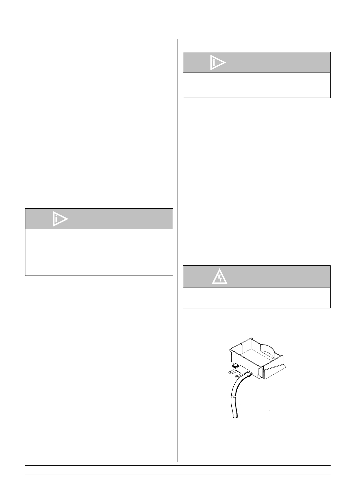
7 - Each drip tray has two diaphragm plugs: if a con tinuous
drain is needed, perforate one of the drain plugs and
connect it to a flexible drain line (see figure 1).
figure 1
8 - The unit doesn’t come presanitized from the factory.
Before serving products, the dispenser must be
disassembled, cleaned and sanitized. a ccording to this
handbook instructions (chapter
5.3 CLEANING AND SANITIZING PROCEDURES).
4 Models 369/370/37 1
Page 5
4 TO OPERATE SAFELY
1 - Do not operate the dispenser without reading this
operator’s manual.
2 - Do not operate the dispenser unless it is properly
grounded.
3 - Do not use extension cords to connect the dispenser.
4 - Do not operate the dispenser unless all panels are
restrained with screws.
5 - Do not obstruct air intake and discharge openings: 15 cm
(6”) minimum air space around all sides of the dispenser.
6 - Do not put objects or fingers in panels louvers and faucet
outlet.
7 - Do not remove bowls, augers and panels for cleaning or
routine maintenance unless the dispenser is disconnected
from its power source.
5 OPERATING PROCEDURES
1 - Clean and sanitize the unit according to the instructions in
this manual. See chapter 5.3 CLEANING AND
SANITIZING PROCEDURES.
2 - Fill the bowls with product to the maximum level mark. Do
not overfill.
The exact quantity of product (expressed as liters and
gallons) is shown by marks on the bowl.
3 - In case of products to be diluted with water, pour water into
bowl first, then add correct quantity of product. It is
advisable to strain the natural fruits to prevent pulps from
obstructing the faucet outlet.
4 - To obtain the best performance and result, use bases
designed to be run in Granita freezers.
If natural juices (e.g. lemon, orange) as well as sugarless
products (e.g. coffee) are used, dissolve 150 - 200 grams
of sugar per liter.
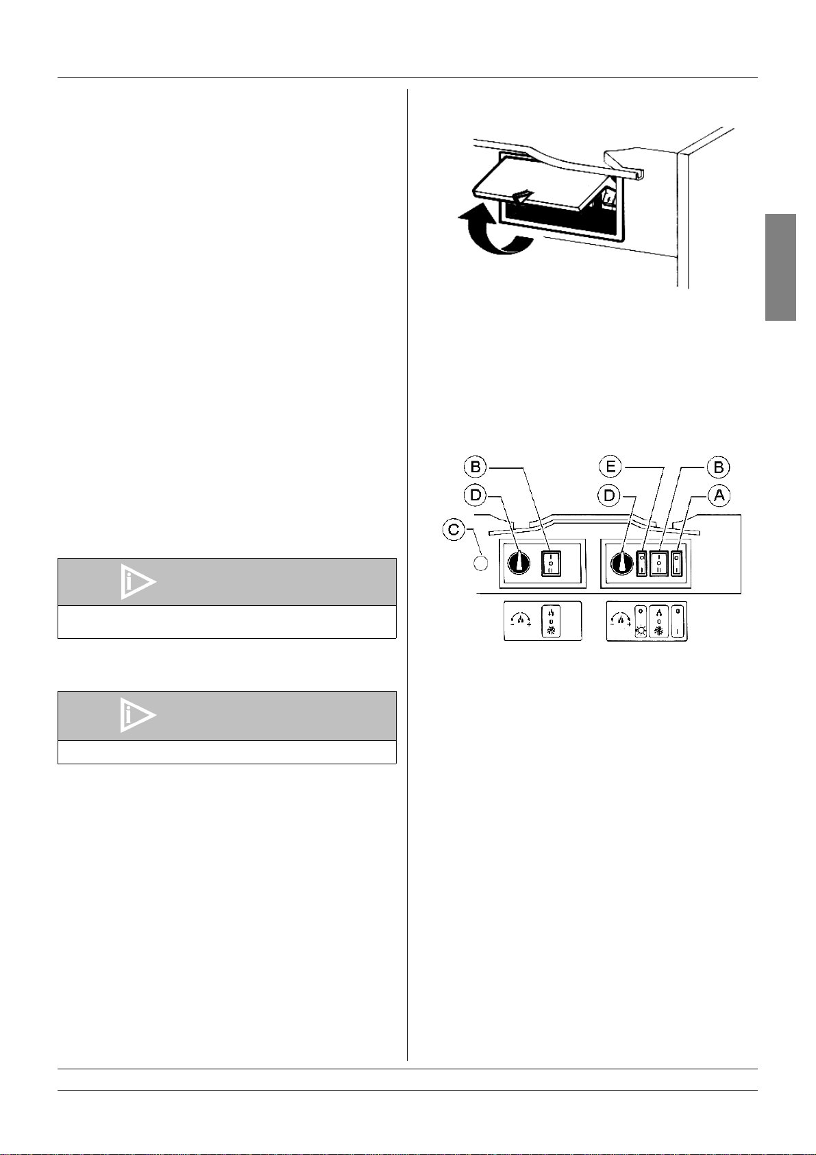
All the switches are located on the faucet side of the dispenser
behind switch covers (see figure 2).
figure 2
In addition all the models except 369 are equipped with an
automatic safety pressure switch to prevent damages to the
compressor. The lighting of the light at the left of the switch
covers indicates insufficient ventilation of the unit. If this occurs
check that there is sufficient space on all sides for ventilation
(at least 15 cm (6”) on each side) and that condenser filter is
free from dust or other obstructions.
In case the warning light is still ON after these operations have
been carried out a service call is required.
Dispenser controls functions are as follows (see figure 3):
ENGLISH
IMPORTANT
Brix (sugar percent content) must be at least 13 for all
granita products.
5 - For soft drink use the unit doesn’t need any minimun brix
level.
IMPORTANT
Operate the dispenser with food products only.
6 - In stall the covers and check that they are correctly placed
over the bowls. The dispenser must always run with the
covers installed to prevent possible contamination of the
product.
7 - Set the control switches as shown in chapter
5.1 DESCRIPTION OF CONTROLS.
8 - Always leave the dispenser on, as the refrigerati on stops
automatically when Granita reaches the proper thickness.
The mixers will continue to turn.
5. 1 DESCRIPTION OF CONTROLS
The dispenser is equipped with a p ower switch and a light
switch. In addition each bowl is individually operated by a
mixer/refrigeration switch. In fact it is possible to dispense both
soft drinks and Granita.
When a bowl is in Soft Drink mode, the beverage temperature
is controlled by the corresponding thermostat.
When a bowl is in Granita mode, the mix viscosity is controlled
by the corresponding adjustment screw located in the rear wall
of each container (for temperature and viscosity setting refer to
chapter 5.2 OPERATION HELPFUL HINTS).
figure 3
Power switch (A)
0 position : power is turned OFF to all functions.
I position : power is turned ON to all functions
and the other switches are enabled.
The fan motor runs.
Light switch (E)
0 position : all top cover lights are OFF.
I position : all top cover lights are ON, provided
that power switch (A) is set to I.
Mixer/refrigeration switch (B)
I position : mixer and refrigeration ON.
SOFT DRINK mode.
0 position : OFF.
II position : mixer and refrigeration ON.
GRANITA mode.
Thermostat (D)
Turn clockwise : to decrease temperature
Turn counterclockwise : to increase temperature
Models 369/370/371 5
Page 6

Safety pressure switch warning light (C)
Warning light ON : insufficient ventilation
To operate the unit:
1 - Set the power switch to I position.
2 - Set the mixer/refrigeration switches as follows:
- to the I position to get soft drink.
- to the II position to get Granita.
3 - Set the light switch to I position.
5. 2 OPERATION HELPFUL HINTS
1 - Granita viscosity adjustment: proper Granita viscosity is
factory preset. If an adjustment is necessary, use a
standard screwdriver to turn the adjustment screw
clockwise to increase viscosity and counterclockwise to
decrease viscosity (see figure 4). When adjusting the
viscosity for a thicker product, the viscosity indicator (Item
F) will lower. When adjusting viscosity for a thinner
product, the indicator (Item F) will rise.
8 - Mixers must not be turned off when frozen product is in the
bowl. If not agitated, the product may freeze to a solid
block of ice. If the mixers are turned back on, damage to
the mixers and their motor may result. Therefore, mixers
may be restarted only after product is melted.
9 - The dispenser is equipped with a magnetic coupling by
which the gear motor (located outside the bowl) drives the
mixers (inside the bowl).
The magnetic drive operates as an “intelligent clutch” able
to automatically disconnect the mixers in case they are
obstructed by ice or other obstacles.
An intermittent dull noise will alert the operator that mixers
are obstructed.
In this case, it is necessary to unplug the unit immediatly,
empty the bowl and eliminate the obstacle.
10 -The dispenser must be able to emit heat.
In case that seems excessive, check that no heating
source is close to the unit and that air flow through the
slotted panels is not obstructed by wall or boxes. Allow at
least 15 cm (6”) of free clearance all around the dispenser.
If the product in the bowls is frozen and the safety
pressure switch warning light is OFF, the unit is running
properly.
11 -Restrictor cap. When the unit is used in Soft Drink mode it
is advisable to install the restrictor cap on the faucet outlet
in order to reduce the flow of liquid from the dispenser (see
figure 5).
figure 4
2 - Beverage temperature adjustment: proper beverage
temperature is factory preset. To reset, turn the knob
located in each switch box as follows:
- clockwise to decrease temperature.
- counterclockwise to increase temperature.
Note: Beverage temperature is controlled by the
thermostat only when the mixer/refrigeration
switch(es) are in I position, (Soft Drink mode).
3 - When the mixer / refrigeration switch(es) are set in the I
position, Soft Drink mode, it is possible to manually stop
the refrigeration by turning the thermostat knob
counterclockwise until it clicks.
4 - The le ngth of time for freeze down of Gran ita is governed
by many variables, such as ambient temperature, mix
initial temperature, sugar content (Brix level) and viscosity
setting.
5 - To shorten Granita recovery time and to increase
productivity, it is advisable to pre-chill the product to be
used in the dispenser.
6 - To shorten Granita recovery time and to increase
productivity, the bowl should be refilled after the product
level drops lower than half of the evaporator cylinder and
at the start of each day.
7 - For good product conservation the dispenser must run
overnight, in the Soft Drink mode.
If this is not possible and product is left in the bowls
overnight, the mixer/refrigeration switches must be set to
the I position at least one hour before the unit is switched
off. This eliminates any block of iced product forming
overnight, which could result in damage to mixers or to
their motor when the unit is switched back on. In any case,
before the unit is restarted, make sure that no blocks of ice
have been formed; if so, they are to be removed before the
unit is switched on. Overnight operation in drink mode also
eliminates possible ice accumulation from condensation
around the bowls.
figure 5
5. 3 CLEANING AND SANITIZING
PROCEDURES
1 - Cleaning and sanitizing of the dispenser are
recommended to guarantee the conservation of the best
product taste and the highest unit efficiency. This section
is a procedural guideline only and is subject to the
requirements of the local Health Authorities.
2 - Prior to the disassembly and clean ing, the machine must
be emptied of product. To do this proceed as follows:
- set the power switch to I position
- set mixer/refrigeration switch(es) to I position (Soft Drink
mode)
- place a pail under each faucet and drain all product from
bowls
- set all control switches to the 0 position
5. 3. 1 DISASSEMBLY
ATTENTION
Before any disassembly and/or cleaning procedure
disconnect the unit from the power supply.
Failure to comply could result in electrical shock.
1 - Remove cover from the bowl.
2 - On 369 MODEL remove the lateral tray by lifting its outer
6 Models 369/370/37 1
Page 7

side up and off the hook located on the opposite side (see
figure 6).
ENGLISH
figure 8
figure 6
3 - Remove the bowl by lifting its faucet side up and off the
fastening hooks (see figure 7) and slide it out (see figure
8).
figure 7
4 - Slide the outer spiral out (see figure 9) and then the inside
auger (see figure 10).
figure 9
figure 10
Models 369/370/371 7
Page 8

5 - Remove the bowl gasket from its seat (see figure 11).
dishwashing detergent. Do not use abrasive detergent.
Important: if present, follow label directions, as too strong
a solution can cause parts damage, while too mild a
solution will not provide adequate cleaning.
IMPORTANT
In order to prevent any damages to the dispenser, use
only a detergent suitable for plastics parts.
2 - Using a brush suitable for the purpose, thoroughly clean all
disassembled parts in the cleaning solution.
figure 11
6 - Dismantle the faucet assembly (see figure 12).
figure 12
7 - Slide the drip tray out and empty it.
5. 3. 2 CLEANING
ATTENTION
When cleaning the machine, do not allow excessive
amounts of water around the electrically operated
components of the unit. Electrical shock or damage to
the machine may result.
3 - Do not immerse the lighted top covers in liquid. Wash them
separately with cleaning solution. Carefully clean the
bottoms of the covers.
4 - In the same manner, clean the evaporator cylinder(s)
using a soft bristle brush.
5 - Rinse all cleaned parts with cool, clean water.
5. 3. 3 SANITIZING
Sanitizing should be performed immediately prior to starting
the machine. Do not allow the unit to sit for extended periods of
time after sanitization.
1 - Wash hands with a suitable antibacterial soap.
2 - Prepare at least two gallons of a warm (45-60 °C / 120-
140 °F) sanitizing solution (100 PPM availa ble chlorine
concentration or 1 spoon of sodium hypoclorite diluted with
half a gallon of water) according to your local Health
Codes and manufacturer’s specifications.
3 - Place the parts in the sanitizing solution for five minutes.
4 - Do not immerse the lighted top covers in liquid. Carefully
wash their undersides with the sanitizing solution.
5 - Place the sanitized parts on a clean dry surface to air dry.
6 - Wipe clean all exterior surfaces of the unit. Do not use
abrasive cleaner.
5. 3. 4 ASSEMBLY
ATTENTION
Before any disassembly and/or cleaning procedure
disconnect the unit from the power su pply.
Failure to comply could result in electrical shock.
1 - Slide the drip tray into place.
2 - Lubri cate faucet piston, inside auger and outer spi ral (see
points A, B and C of figu re 13) only with the grea se
supplied by the manufacturer or other food grade
approved lubricant.
IMPORTANT
Do not attempt to wash any machine components in a
dishwasher.
IMPORTANT
Prior to any cleaning or sanitizing procedure hands
washing is required.
1 - Prepare at least two gallons of a mild cleaning solution of
warm (45-60 °C / 120-140 °F) potable water and
3 - Assemble the faucet by reversing the disassembly steps
8 Models 369/370/37 1
figure 13
Page 9

(see figure 12)
4 - Fit bowl gasket around its seat.
Note: the largest brim of gasket must face against the rear
wall (see figure 14).
properly engaged (see figure 17).
ENGLISH
figure 17
figure 14
5 - Carefully insert the auger into the evapo rator use caution
to prevent it from hitting the rear wall (see figure 15).
figure 15
6 - Install the outer spiral. Slide it over the evaporator until its
front notch engages with the exposed end of the auger
shaft (see figure 16).
8 - On 369 MODEL install the lateral tray by reversing the
disassembly steps (see figure 6).
9 - Use fresh product to chase any remaining sanitizer from
the bottom of the bowl(s). Drain this solution. Do not rinse
out the machine.
5. 4 IN-PLACE SANITIZATION
The In-Place Sanitization prior to starting the ma chine may be
performed prior to starting the machine, if needed, this should
only be performed, in addition to the Disassembled Parts
Sanitization, but never in lieu of it.
1 - Prepare two gallons of a warm (45-60°C / 120-140 °F)
sanitizing solution (100 PPM available chlorine
concentration or 1 spoon of sodium hypoclorite diluted with
half a gallon of water) according to your local Health
Codes and manufacturer’s specifications.
2 - Pour the solution into th e bo w l ( s).
3 - Using a brush suitable for the purpo se, wipe the solution
on all surfaces protruding above the solution-level and on
the underside of the top cover(s).
4 - Install the top cover(s) and operate the unit. Allow the
solution to agitate for about two minutes. Drain the solution
out of the bowl(s).
5 - Use fresh product to chase any remaining sanitizer from
the bottom of the bowl(s). Drain this solution. Do not rinse
out the machine.
6 ROUTINE MAINTENANCE
ATTENTION
A damaged power cord must be replaced by an
authorized service agent. Failure to comply main result
in electric shock.
1 - Daily: inspect the mach ine for signs of product leaks past
figure 16
7 - Push the bowl toward the rear wall of the unit until it fits
snugly around the gasket and its front fastening hooks are
Models 369/370/371 9
seals and gaskets. If proper assembly does not stop leaks
around seals or gaskets, check for improper lubrication,
worn or damaged parts. Replace parts as needed.
2 - Monthly on 369, 370 and 371 models: remove the dust
Page 10

from the condenser filter.
ATTENTION
Before performing any disassembly and/or cleaning
disconnect the unit from the power su pply.
Failure to comply could result in electrical shock.
Remove the only left panel (from faucet side) unscrewing
the two plastic coated screws (see figure 18).
6. 1 MAINTENANCE (TO BE CARRIED OUT
BY QUALIFIED SERVICE PERSONNEL
ONLY)
1 - Monthly on 370 model: remove the dust from the
condenser. To do this unplug the unit or switch off the 2pole wall breaker and then remove the panels.
2 - Annually: remove the panels and clean the inside of the
machine including the base, side panels, condenser, etc.
3 - When installed, the anti-splash filters inside the slotted
panels must not be removed.
4 - Never remove the insulating jacket from around the
suction tubing of the evaporator (the copper tubing located
on the right side of gear motor). If the insulating jacket is
missing replace the entire parts with original spare parts
from the supplier.
5 - In order to prevent any damages to the dispenser, all
plastics parts must be lubricated only with grease supplied
by the manufacturer or with another lubricating product
suitable for polycarbonate.
IMPORTANT
The electric diagram of the dispenser is located inside
the dispensing side panel.
7 DEFROST TIMER (OPTIONAL)
The Defrost Timer, located on the right side of the unit,
automatically switches the dispenser from Granita mode to
Soft Drink mode and the opposite. This means that during
defrost periods frozen Granita will melt to thermostat setting
temperature and once defrost period has expired, the product
automatically freezes down again to Granita setting viscosity.
figure 18
3 - Replacement of lighted top cover bulb: remove the scre w
placed in the upper part of the top cover, remove the lower
part and replace the bulb (using a 24-28V 21W max bulb).
Reassemble the top cover and replace the screw.(see
figure 19)
figure 19
ATTENTION
figure 20
To operate the defrost timer proceed as follows (see figure 20).
Condenser fins are very sharp. Use extreme caution
when cleaning.
1 - Set the time of the day by rotating the dial clockwise (arrow
A). Never rotate the timer counterclockwise as this
would damage the internal machanism. Align the current
10 Models 369/370/371
Page 11

time of day with the arrow B on the timer face. This is a 24
hour timer showing both A.M. and P.M.
2 - Program the defrost timer by pushing out on the tabs C
that correspond to the hours desired to defrost. Each tab
represents 15 minutes. A minimum of four to eight hours
are required to defrost frozen beverage (depending on
ambient conditions).
Note: when all the tabs are pushed in the defrost function is
OFF (the machine operates as if it were not equipped with
Defrost Timer).
ENGLISH
Models 369/370/371 11
Page 12

OPERATOR PARTS IDENTIFICATION
2471_01 V 3.5 04I09
MODEL 369/370/371
Page 13

1 047634 Cover-Hopper-Transparent 27 >>> Relay-Start (Compressor) 57 046510 Knob-Temperature Control
2 046456 Hopper-10.7 Qt./10 Liter 28 >>> Overload protector 58 PPP Transformer-Light bulb
3 046457 Valve-Draw 29 >>> Capacitors 59 052212 Insulation-Flange-Foam
4 046458 O-Ring-Draw Valve 30 047405 Leg-4” 8MM Thread 60 057895 Housing-Electronic Board
5 046459 Handle-Draw blue 30 046484 Leg 61 048108 Cover A.-Hopper-Lighted (115V 60Hz - 220V 60Hz)
5 046459-1 Handle-Draw (Black) 31 053151-27 Coil-Solenoid Valve (230V 50Hz) 61 057903 Cover A.-Hopper-Lighted (230V 50Hz - 240V 50Hz)
6 046460 Spring-Draw 31 053151-27 Coil-Solenoid Valve (240V 50Hz) 62 049659 Timer - Defrost 24 Hour
7 046461 Pin-Pivot blue 31 053151-12 Coil-Solenoid Valve (115V 60Hz) 63 050653 Cap-Restrictor
7 046461-1 Pin-Pivot (Black) 31 053151-27 Coil-Solenoid Valve (220V 60Hz) 64 057878 O-Ring - Gear Shaft (4th)
8 062250
Thrust washer rubber cap 32 059558
Damper-vibration *369-371
65 048872 Stainless steel fixing screw for panel
9 046463 Gasket-Hopper 33 046486 Screw-Viscosity Adjustment 66 052213-34 Gear-Motor-Generation III (230V 50Hz)
10 052202 Bearing-Outer-Rear Wall 34 046487 Nut-Viscosity Adjustment 66 052213-44 Gear-Motor-Generation III (240V 50Hz)
11 052203 Bearing-Beater-Hub 35 046488 Spring-Viscosity Adjustment 66 052213-12 Gear-Motor-Generation III (115V 60Hz)
12 052204 Beater-Magnetic 36 046489 Switch-Lever 66 052213-27 Gear-Motor-Generation III (220V 60Hz)
13 056754 Blade-Scaper-Outer Spiral 37 052206 Bearing-Inner Rear Wall-Hex 67 046494 Bearing-Rear Gear motor cover
14 048090 Box-Switch 38 052207 Washer-Inner Drive Magnet 68 059463 Cover-Rear Gear Motor
15 048091 Box-Switch Power 39 052208 Magnet-Inner Drive 69 046493 Screw-Gear Motor Cover
16 057899 Panel front (369P) 40 052209 Bearing-Flange Round 70 046499 Panel-Side-Left
16 048170 Panel front (370) 41 052210 O-Ring Flange-Red 71 057894-27 Light-Amber-Warning (230V 50Hz)
16 048160 Panel front (371) 42 052211 Flange-Gear Motor-Plastic 71 057894-27 Light-Amber-Warning (240V 50Hz)
17 046471 Cover-Switch box 43 PPP Board-Electronic Delay 71 052200 Light-Amber-Warning (115V 60Hz)
18 048092 Switch 3-Position 44 053088 Panel-Rear (369P) 71 052200 Light-Amber-Warning (220V 60Hz)
19 056727 Switch-Rocker 44 048095 Panel-Rear (370) 72 052214 Switch-High Pressure Cut Out
20 046474 Block-Terminal 44 048097 Panel-Rear (371) 73 052201 Filter-Condenser
21 046475 Clip-Front Panel 45 046498 Panel-Side-Right - no Defrost Timer 74 052216 Screw-Thumb-Panel
22 046476 Boot-Terminal Block 45 049658 Panel-Side-Right - Defrost Timer 75 053089 Upper Tray-Drip
23 046477-34 Motor-Fan (230V 50Hz) 46 046500 Cover-Lighted Display 76 057879 Upper Panel
23 046477-34 Motor-Fan (240V 50Hz) 47 046911 Card-Flavor Packet (Orange, Lemon, Cherry, Lemon-Lime, Cappuccino) 77 053323 Timer cover (115V 60Hz)
23 046477-12 Motor-Fan (115V 60Hz) 48 046501 Lens-Lighted Display 77 048872 Timer cover (220V 60Hz - 230V 50Hz - 240V 50Hz)
23 046477-34 Motor-Fan (220V 60Hz) 49
24 PPP Blade-
Fan 50 046503 Contact-Lighted Display 79
25 053086 Shield-Splash (369P) 51 057878 Bulb-Light 28V 80
25 046479 Shield-Splash (370) 52 057881 Socket-Light 81
046502 Base-Lighted Display 78 053151-13 Solenoid valve plastic cap
059464
059465
062249
Cover-rear picture
Cover-rear picture screen
Thrust washer
25 046479 Shield-Splash (371) 53 046506 Wire-Light
26 053087 Tray-Drip (369P) 54 046507 Contact-Flexible PPP See next table
26 046480 Tray-Drip (370) 55 046508 Ring-Flexible Contact >>> Please order what printed on piece
26 046480 Tray-Drip (371) 56 046509 Control-Temperature
230V 50Hz 240V 50Hz 115V 60Hz 220V 60Hz
24 (369P) 046478 046478 046478 046478
24 (370/371) 048162 048162 046478 046478
43 (369P) 057890 057890 057889 057889
43 (370) 057891 057891 057889 057889
43 (371) 057892 057892 057889 057889
58 (369P) 057898 046479 048356-12 057898
58 (370) 057896 057896 046511-12 057896
58 (371) 057897 057897 048355-12 057897
Page 14

GEAR MOTOR
052213-12
052213-27
052213-34
052213-44
1 052042 Bracket-Gear Motor w/Bushing 8 052047 Cap-Ball Bearing 19 052052 Gasket-Gear Motor
2 057900 Stator-Gear Motor (230V / 50Hz) 9 057878 O-Ring-Gearshaft 20 052053 C over -Gear box
2 057901 Stator-Gear Motor (220V / 60Hz) 10 046521 Bearing-Ball (2) 21 052054 Spring-Viscosity spring
2 057902 Stator-Gear Motor (240V / 50Hz) 11 052049 Spacer-1.5 MM 22 049027 Rotor-Gear Motor
2 046514-12 Stator-Gear Motor (115V / 60Hz) 12 046523 Gear-Third 23 049026 Pinion-Gear Motor
3 052043 Cover-Stator 13 052217 Gear-Fourth 24 052055 Bushing-Gear Motor
4 052044 Washer-Gear Motor 14 052050 Spacer-3.3 MM 25 052056 Washer-Gear Motor
5 052046 Spacer-Rotor (Gear Motor) 15 052051 Cap-Bushing 26 052057 Screw-Stator
6 052045 Gear Motor assembly with bushing 17 050218 Gear-First
7 046518 Retainer-Seal 18 050217 Gear-Second
Motor-Gear *369,370,371* GEN 3
(Magnetic Drive - BR 0067955/Up)
Include:
Page 15

Troubleshooting Guide
PROBLEM PROBABLE CAUSE REMEDY
1 - Product is too stiff. a - Improper mixing of product.
a - Carefully follow directions for mixing
product.
b - Mix low condition.
c - Viscosity needs adjustment.
2 - Product is too soft. a - Improper mixing of product.
b - Viscosity needs adjustment.
3 - No product is being dispensed. a - Improper mixing of product.
b - Product frozen up in evaporator.
c - Beater shaft not rotating. Power switch
is not in the “I” position and the mix
refrigeration switch is not in the “I” or “II”
position.
4 - The freezer will not operate with the
power switch in the “I” and the mix
refrigeration switch in the “I” or “II”
position.
5 - Excessive mix leakage from door
spout.
a - The unit is unplugged.
b - Blown fuse, or the circuit braker is off.
c - The beater is off on high pressure cut
out (amber light is lit).
a - Improper or inadequate lubrication of
draw valve o-rings.
b - Wrong type of lubricant on draw valve
o-rings.
b - Add mix to mix hopper.
c - Adjust accordingly.
a - Carefully follow directions for mixing
product.
b - Adjust accordingly.
a - Carefully follow directions for mixing
product.
b - Adjust viscosity accordingly.
c - The power switch must be in “I” and the
mix refrigeration switch in the “I” or “II”
position.
a - Check the plug at wall receptacle.
b - Replace the fuse or turn the braker on.
c - Clean the filter or provide a dequate
ventilation.
a - Lubricate properly.
b - Use food grade lubricant (example:
Taylor lube).
c - Worn or missing drawvalve o-rings.
c - Replace or install o-rings on draw valve.
Parts Replacement Schedule
PART DESCRIPTION EVERY 3 MONTHS EVERY 6 MONTHS
Outer Spiral Scraper Blade Inspect & Replace as Necessary Minimum
Rear Hopper Gasket Inspect & Replace as Necessary
Draw Valve O-Ring X
IMPORTANT: The display light bulb must be replaced with the factory authorized replacement bulb. Failure
to comply may result in component damage or severe personal injury due to broken glass.
Models 369/370/371 15
Page 16

046445-M
2471_01 R0.4 04I09
 Loading...