

Page 1

SERVICE
MANUAL
Model 358 & 359
Thick Shake Dessert Machines
Service Manual
056788-S 8/27/10 (Original Publication)
(Updated 2/19/14)
Page 2

Page 3

Table of Contents
Section 1: Introduction 1...............................................
Safety 2.............................................................
Model 358 Specifications 4.............................................
Model 359 Specifications 5.............................................
Running Specifications 6...............................................
General Installation Instructions 7.......................................
Refrigerant 9.........................................................
Environmental Notices 10...............................................
Section 2: Controls & Systems 11........................................
Thermistor Control 12..................................................
Thermistor Curve 14...................................................
Refrigeration System 15................................................
Maintaining Quality 16..................................................
Section 3: Troubleshooting 17...........................................
Troubleshooting Thermistor Components 18..............................
General Troubleshooting Guide 19.......................................
Overrun 22............................................................
Section 4: General Service 23............................................
Evaporator Oil 24......................................................
Rear Bearing Unit Alignment 25..........................................
Pulley Alignment 26....................................................
Rear Shell Bearing 26..................................................
Beater Shaft Removal 26...............................................
Preventative Maintenance 27............................................
Models 358 & 359 Table of Contents
Page 4

Table of Contents - Page 2
Section 5: Parts 29......................................................
Parts Warranty Explanation 30...........................................
Model 358 Operator Parts 31............................................
Model 358 Exploded View 32............................................
Model 358 Shell Assembly 34...........................................
Model 358 Control A. (X66731-33) 35....................................
Model 358 Channel A.-Control (X63534) 36...............................
Models 358 & 359 Beater Door Assembly 38..............................
Model 359 Operator Parts 39............................................
Model 359 Exploded View 40............................................
Model 359 Shell Assembly 42...........................................
Model 359 Channel A.-Control (X65222) 43...............................
Model 359 Control A. (X65279-33) 44....................................
Models 358 & 359 Switch A.-Draw (X65212-SER) 45.......................
Models 358 & 359 Accessories 46.......................................
Parts List 47...........................................................
Wiring Diagrams 54....................................................
CAUTION: Information in this manual is intended to be used by Taylor Authorized
Service T echnicians only.
Note: Continuing research results in steady improvements; therefore, information
in this manual is subject to change without notice.
E August, 2010 Taylor (Original Publication)
(Updated March, 2011)
All rights reserved.
056788-S
The word Taylor and theCrown design
are registered trademarks in the United States
of America and certain other countries.
Taylor Company
750 N. Blackhawk Blvd.
Rockton, IL 61072
Table of Contents Models 358 & 359
Page 5

Section 1: Introduction
S Safety
S Specifications
S Running Specifications
S General Installation Instructions
S Refrigerant
S Environmental Notices
Models 358 & 359
1
Introduction
Page 6
Safety
______________________________
We, at Taylor Company, are deeply committed to
manufacturing safe operating and serviceable
equipment. The many built-in safety features that
are part of all Taylor equipment are aimed at
protecting operators and trained service technicians
alike.
This manual is intended exclusively for
Taylor Company authorized service personnel.
DO NOT attempt to run the equipment
unless you have been properly trained to do so.
Failure to follow this instruction may result in
equipment damage, poor equipment performance,
health hazards, or personal injury.
CAUTION: THIS EQUIPMENT MUST BE
PROPERLY GROUNDED! Do not operate this unit
unless it is properly grounded and all service panels
and access doors are restrained with screws. Failure
to do so can result in severe personal injury from
electrical shock!
protect against the leakage of current, and
be installed by authorized personnel to the
local codes.
S Supply cords used with this unit shall be
oil-resistant, sheathed flexible cable, not
lighter than ordinary polychloroprene or
other equivalent synthetic
elastomer-sheathed cord, (Code designation
60245 IEC 57) installed with the proper cord
anchorage to relieve conductors from strain,
including twisting, at the terminals and
protect the insulation of the conductors from
abrasion.
Failure to follow these instructions may result in
electrocution or damage to the unit.
This unit is provided with an equipotential
grounding lug that is to be properly attached to
either the rear of the frame or the under side of the
base pan near the entry hole for incoming power, by
the authorized installer. The installation location is
marked by the equipotential bonding symbol (5021
of IEC 60417-1) on both the removable panel and
the equipment's frame, as well as on the diagram.
S DO NOT attempt any repairs unless the
main power supply to the unit has been
disconnected.
S DO NOT operate the unit with larger fuses
than specified on the data label.
S Stationary appliances which are not
equipped with a power cord and a plug or
other device to disconnect the appliance
from the power source must have an all-pole
disconnecting device with a contact gap of
at least 3 mm installed in the external
installation.
S Appliances that are permanently connected
to fixed wiring and for which leakage
currents may exceed 10 mA, particularly
when disconnected, not used for long
periods, or during initial installation, shall
have protective devices such as a GFI to
DO NOT remove the freezer door or any
internal operating parts (examples: beater, scraper
blades, etc.) unless all control switches are in the
OFF position. Failure to follow these instructions
may result in severe personal injury from hazardous
moving parts.
THIS UNIT HAS MANY SHARP EDGES
THAT CAN CAUSE SEVERE INJURIES.
This unit must be installed on a level
surface to avoid the hazard of tipping. Extreme care
should be taken in moving this equipment for any
reason.
Two or more people are required to safely move this
unit. Failure to comply may result in personal injury
or equipment damage.
Introduction
2
Models 358 & 359
Page 7

This unit must NOT beinstalledinanarea
where a water jet or hose can be used. NEVER use
a water jet or hose to rinse or clean this unit. Using a
water jet or hose on or around this equipment may
result in the electrocution of the user or damage to
the equipment.
Cleaning and sanitizing schedules are
governed by your state or local regulatory agencies
and must be followed accordingly. Please refer to
the cleaning section of the Operator Manual for the
proper procedure to clean this unit.
Models 358 & 359
3
Introduction
Page 8
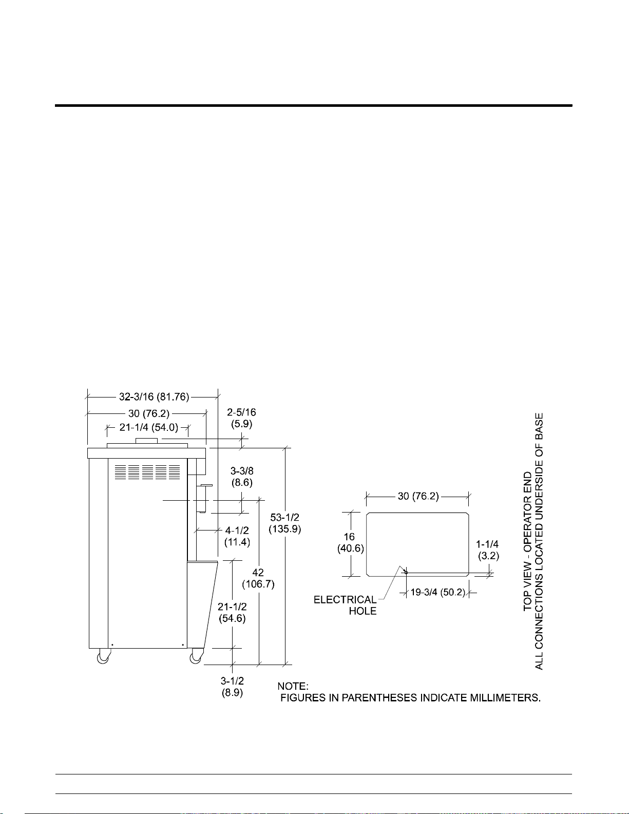
Model 358 Specifications
S Freezing Cylinder - One; 7 quart (6.6 liter)
capacity.
S Mix Hopper - One; 20 quart (18.9 liter)
capacity. Refrigerated and insulated.
S Beater Motor - One; 1.5 hp.
S Refrigeration Unit - One; approximately
9,500 btu/hr compressor. Refrigerant 404A.
S Electrical - Standard is 208/230-60-3;
however, other electrical characteristics are
available. Each unit requires electrical
service.*
Three Phase Maximum Fuse Size: 20A
Minimum Circuit Ampacity: 16A
*For exact electrical information, always refer
to the data label of the unit.
S Air Cooled - Clearance: 3” (76 mm) around
all sides.
S Dimensions -
Width: 16” (406 mm)
Depth: 30” (762 mm)
Height: 55-7/8” (1418 mm)
Floor Clearance: 3-1/2” (89 mm) mounted
on standard casters.
S Approximate Weights -
Net: 356 lbs. (161.5 kgs.)
Crated: 400 lbs. (181.4 kgs.)
Volume: 22.3 cu. ft. (.63 cu. m.)
Availability and specifications subject to change
without notice.
Introduction
Figure 1
4
Models 358 & 359
Page 9
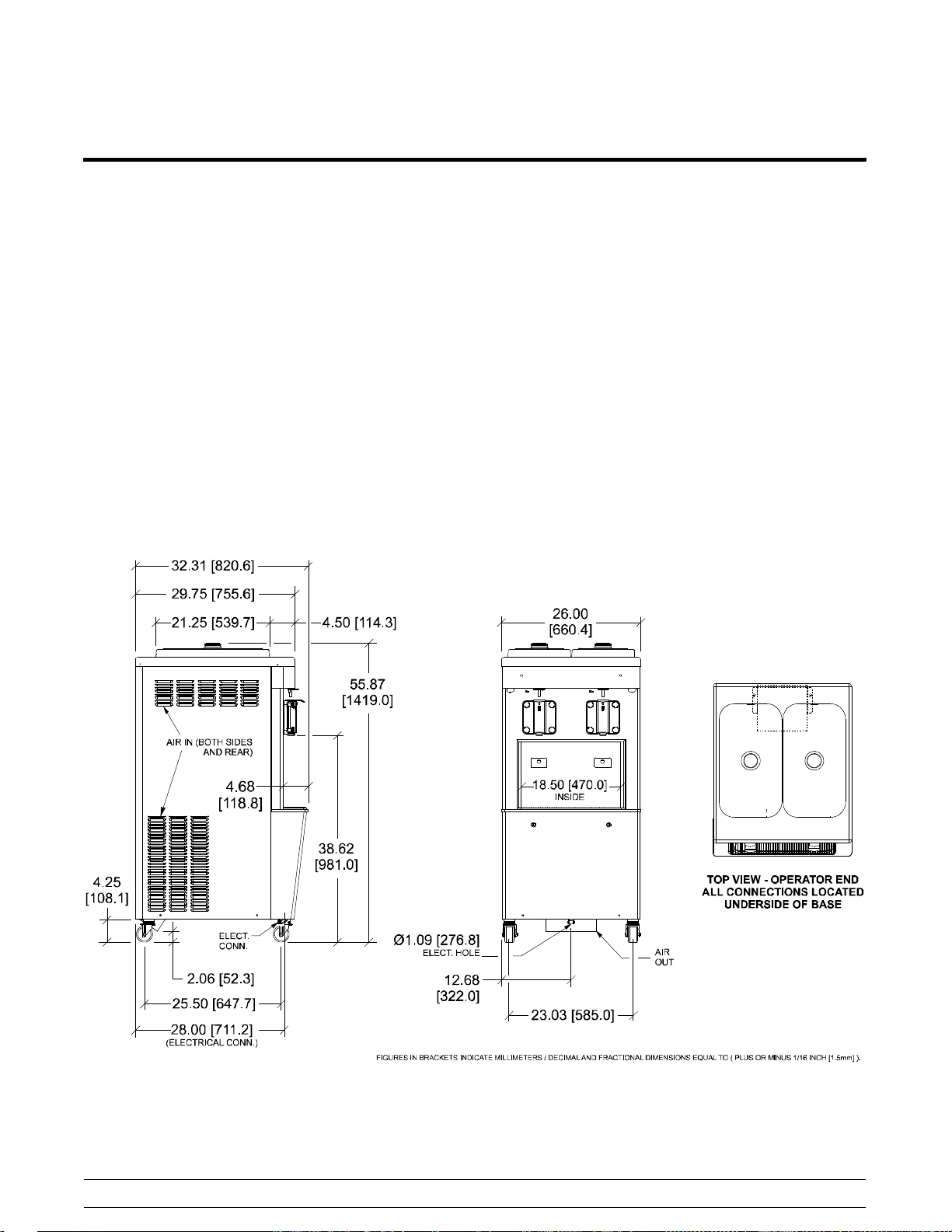
Model 359 Specifications
S Freezing Cylinder - Two; 7 quart (6.6 liter)
capacity.
S Mix Hopper - Two; 20 quart (18.9 liter)
capacity. Refrigerated and insulated.
S Beater Motor - Two; 1.5 hp.
S Refrigeration Unit - Two; approximately
9,500 btu/hr compressors. Refrigerant 404A.
S Electrical - Standard is 208/230-60-3;
however, other electrical characteristics are
available.
Each unit requires electrical service.*
Maximum Fuse Size: 35A
Minimum Circuit Ampacity: 30A
*For exact electrical information, always refer
to the data label of the unit.
S Air Cooled - Clearance: 3” (76 mm) around
all sides.
S Dimensions -
Width: 26” (660 mm)
Depth: 32-3/8” (822 mm)
Height: 55-7/8” (1418 mm)
Floor Clearance: 4-1/4” (108 mm) mounted
on standard casters.
S Approximate Weights -
Net: 580 lbs. (263.1 kgs.)
Crated: 673 lbs. (305.3 kgs.)
Volume: 41.1 cu. ft. (1.16 cu. m.)
Availability and specifications subject to change
without notice.
Models 358 & 359
Figure 2
5
140219
Introduction
Page 10

Running Specifications
Expansion Valve Setting
404A/HP62: 20 - 22 PSI (138 - 152 kPa)
Low Side Pressure
Low side pressure = expansion valve setting
To adjust the low side pressure, place the gauge on
the low side suction port at the compressor. With the
compressor running, turn the adjustment knob of the
automatic expansion valve clockwise to raise the low
side pressure and counterclockwise to lower the
pressure.
High Side Pressure
Air Cooled: The following chart indicates normal
operating head pressures at various ambient
temperatures:
Ambient Temperature Normal Operating Head
Pressures
F C PSI
70_ 21.1_ 240 -- 270
(1,655 -- 1,862 kPa)
80_ 26.7_ 270 -- 300
(1,862 -- 2,069 kPa)
90_ 32.2_ 300 -- 340
(2,069 -- 2,344 kPa)
100_ 37.8_ 340 -- 380
(2,344 -- 2,620 kPa)
Water Cooled: Thehighsidepressureforwater
cooled units is determined by the water valve. The
water valve is factory set to maintain a high pressure
of 235 PSI (1,620 kPa). To adjust the high pressure,
place the gauge on the high side access port. Turn
the adjustment knob on the water valve clockwise to
lower the high side pressure and counterclockwise
to raise the pressure.
The high side pressure switch is factory set at 440
PSI (3,034kPa) for 404A/HP62. In the event of a
water loss, this switch will sense a rise in pressure
and deactivate the unit.
EPR Valve Setting
The product temperature in the mix hopper is
maintained by the main refrigeration system and can
be adjusted by the EPR (evaporator pressure
regulator) valve. The EPR valve is factory set at 67 69 PSI (462 - 476 kPa) in order to maintain hopper
product temperature below 40_F(4_C). To adjust
the hopper temperature, place the gauge on the
access port at the inlet of the EPR valve. With the
compressor running, loosen the locking nut and turn
the adjustment screw (located on the top of the
valve) clockwise to raise hopper temperature and
counterclockwise to lower the temperature. When
the adjustment is complete, tighten the locking nut.
Introduction
6
Models 358 & 359
Page 11
General Installation Instructions
CAUTION: Only trained, authorized service
technicians should install this equipment. Failure to
comply will void the factory warranty.
The following are general installation instructions.
For complete installation details, please see the
checkout card.
This unit must be installed on a level
surface to avoid the hazard of tipping. Extreme care
should be taken in moving this equipment for any
reason.
Two or more people are required to safely move this
unit. Failure to comply may result in personal injury
or equipment damage.
ALL WIRING AND PLUMBING MUST
CONFORM TO NATIONAL AND LOCAL CODES.
INSTALL POTABLE WATER CONNECTION
WITH ADEQUATE BACK-FLOW
PROTECTION TO COMPLY WITH
APPLICABLE NATIONAL, STATE AND
LOCAL CODES.
Site Preparation
Review the area the unit is to be installed in before
uncrating the unit. Make sure that all possible
hazards to the user and the equipment have been
addressed.
Clearance: Air Cooled Units
Air cooled units require a minimum of 3” (76 mm) of
clearance around all sides of the unit. Failure to
allow for adequate clearance can reduce the
refrigeration capacity of the unit and possibly cause
damage to the compressor.
For Indoor Use Only: This unit is designed to
operate indoors, under normal ambient
temperatures of 70_ -75_F(21_ -24_C). The
machine has successfully performed in high ambient
temperatures of 104_(40_C) at reduced capacities.
This unit must NOT beinstalledinanarea
where a water jet or hose can be used. NEVER use
a water jet or hose to rinse or clean this unit. Using a
water jet or hose on or around this equipment may
result in the electrocution of the user or damage to
the equipment.
Uncrate the machine. Inspect the unit for damage.
Report any damage to the Taylor factory
immediately.
This piece of equipment is made in the USA and has
USA sizes of hardware. All metric conversions are
approximate and vary in size.
Installer Safety
In all areas of the world, equipment should
be installed in accordance with existing local codes.
Please contact your local authorities if you have any
questions.
Care should be taken to ensure that all basic safety
practices are followed during the installation and
servicing activities related to the installation and
service of Taylor equipment.
S Only authorized Taylor service personnel
should perform installation and repairs on
the equipment.
S Authorized service personnel should consult
OSHA Standard 29CFRI910.147 or the
applicable code of the local area for the
industry standards on lockout/tagout
procedures before beginning any installation
or repairs.
S Authorized service personnel must ensure
that the proper PPE (Personal Protective
Equipment) is available and worn when
required during installation and service.
S Authorized service personnel must remove
all metal jewelry, rings, and watches before
working on electrical equipment.
THIS UNIT HAS MANY SHARP EDGES
THAT CAN CAUSE SEVERE INJURIES.
Models 358 & 359
7
Introduction
Page 12
Electrical Connectio n s
In the United States, this equipment is
intended to be installed in accordance with the
National Electrical Code (NEC), ANSI/NFPA
70-1987. The purpose of the NEC code is the
practical safeguarding of persons and property from
hazards arising from the use of electricity. This code
contains provisions considered necessary for safety.
In all other areas of the world, equipment should be
installed in accordance with the existing local codes.
Please contact your local authorities.
Each machine requires one power supply. Check
the data label on the machine for fuse, circuit
ampacity and other electrical specifications. Refer to
the wiring diagram provided inside the control box
for proper power connections.
It is recommended that the machine be plugged into
an electrical surge protector for added protection
against power surges which could damage an
electrical/electronics component. An electrical surge
event may cause the unit to shut down. Such an
event would require service by a qualified service
technician if the machine was not adequately
protected. A good surge protector, as would
normally be used on a home computer, should be
adequate. They are available at most computer retail
outlets or electrical supply stores.
FOLLOW YOUR LOCAL ELECTRICAL CODES!
CAUTION: THIS EQUIPMENT MUST BE
PROPERLY GROUNDED! FAILURE TO DO SO
CAN RESULT IN SEVERE PERSONAL INJURY
FROM ELECTRICAL SHOCK!
Note: This unit is provided with an equipotential
grounding lug that is to be properly attached to
either the rear of the frame or the under side of the
base pan near the entry hole for incoming power, by
the authorized installer. The installation location is
marked by the equipotential bonding symbol (5021
of IEC 60417-1) on both the removable panel and
the equipment's frame, as well as on the diagram.
S DO NOT operate the machine with larger
fuses than specified on the data label.
S Stationary appliances which are not
equipped with a power cord and a plug or
another device to disconnect the appliance
from the power source must have an all-pole
disconnecting device with a contact gap of
at least 3 mm installed in the external
installation.
S Appliances that are permanently connected
to fixed wiring and for which leakage
currents may exceed 10 mA, particularly
when disconnected, not used for long
periods, or during initial installation, shall
have protective devices such as a GFI to
protect against the leakage of current, and
be installed by authorized personnel to the
local codes.
S Supply cords used with this unit shall be
oil-resistant, sheathed flexible cable, not
lighter than ordinary polychloroprene or
other equivalent synthetic
elastomer-sheathed cord (Code designation
60245 IEC 57) installed with the proper cord
anchorage to relieve conductors from strain,
including twisting, at the terminals and
protect the insulation of the conductors from
abrasion.
Failure to follow these instructions may result in
electrocution or damage to the machine.
Introduction
8
Models 358 & 359
Page 13

Refrigerant
______________________________
Compressor Warranty Disclaimer
In consideration of our environment, Taylor proudly
uses only earth friendly HFC refrigerants. The HFC
refrigerant used in this unit is R404A. This
refrigerant is generally considered non-toxic and
non-flammable, with an Ozone Depleting Potential
(ODP) of zero (0).
However, any gas under pressure is potentially
hazardous and must be handled with caution.
NEVER fill any refrigerant cylinder completely with
liquid. Filling the cylinder to approximately 80% will
allow for normal expansion.
Refrigerant liquid sprayed onto the skin may
cause serious damage to tissue. Keep eyes and skin
protected. If refrigerant burns should occur, flush
immediately with cold water. If burns are severe,
apply ice packs and contact a physician
immediately.
Taylor reminds technicians to be cautious of
government laws regarding refrigerant recovery,
recycling, and reclaiming systems. If you have any
questions regarding these laws, please contact the
factory Service Department.
WARNING: R404A refrigerant used in
conjunction with polyolester oils is extremely
moisture absorbent. When opening a refrigeration
system, the maximum time the system is open must
not exceed 15 minutes. Cap all open tubing to
prevent humid air or water from being absorbed by
the oil.
The refrigeration compressor(s) on this machine are
warranted for the term indicated on the warranty
card accompanying this machine. However, due to
the Montreal Protocol and the U.S. Clean Air Act
Amendments of 1990, many new refrigerants are
being tested and developed; thus seeking their way
into the service industry. Some of these new
refrigerants are being advertised as drop-in
replacements for numerous applications. It should
be noted that in the event of ordinary service to this
machine's refrigeration system, only the refrigerant
specified on the affixed data label should be used.
The unauthorized use of alternate refrigerants will
void your compressor warranty. It will be the owners'
responsibility to make this fact known to any
technicians they employ.
It should be noted that Taylor does not warrant the
refrigerant used in its equipment. For example, if the
refrigerant is lost during the course of ordinary
service to this machine, Taylor has no obligation to
either supply or provide its replacement, either at
billable or unbillable terms. Taylor does have the
obligation to recommend a suitable replacement if
the original refrigerant is banned, obsoleted, or no
longer available during the five year warranty of the
compressor.
Taylor will continue to monitor the industry and test
new alternate refrigerants as they are being
developed. Should a new alternate prove, through
our testing, that it would be accepted as a drop-in
replacement, then the above disclaimer would
become null and void. To find out the current status
of an alternate refrigerant as it relates to your
compressor, call the local Taylor Distributor or the
Taylor Factory. Be prepared to provide the
model/serial number of the unit in question.
Models 358 & 359
9
Introduction
Page 14

Environmental Notices
______________________________
In consideration of our environment, Taylor proudly
uses only earth friendly HFC refrigerants. The HFC
refrigerant used in this unit is R404A. This
refrigerant is generally considered non-toxic and
non-flammable, with an Ozone Depleting Potential
(ODP) of zero (0).
However, any gas under pressure is potentially
hazardous and must be handled with caution.
If the crossed out wheeled bin symbol is
affixed to this product, it signifies that this product is
compliant with the EU Directive as well as other
similar legislation in effect after August 13, 2005.
Therefore, it must be collected separately after its
use is completed, and cannot be disposed as
unsorted municipal waste.
The user is responsible for returning the product to
the appropriate collection facility, as specified by
your local code.
For additional information regarding applicable local
laws, please contact the municipal facility and/or
local distributor.
NOISE LEVEL: Airborne noise emission does not
exceed 78 dB(A) when measured at a distance of
1.0 meter from the surface of the machine and at a
height of 1.6 meters from the floor.
Introduction
10
Models 358 & 359
Page 15

Section 2: Controls & Systems
S Thermistor Control
S Thermistor Curve
S Refrigeration System
S Maintaining Quality
Models 358 & 359
11
Controls & Systems
Page 16

Thermistor Control
Function
The thermistor control maintains product
temperature in the freezing cylinder by monitoring
the resistance of the thermistor probe.
Thermistor Probe (038061--20)
The resistance value of the thermistor probe
corresponds with the product temperature in the
freezing cylinder. As the product becomes colder,
the probe resistance increases. As the product
becomes warmer, the probe resistance decreases.
Approximate probe resistance readings:
S 10,000 OHMS at room temperature
(77°F/25°C)
S 46,012 OHMS at product temperature
(20°F/-6.6°C)
Anticipator
The anticipator signals the thermistor control to
activate the refrigeration system whenever product
is drawn. As the draw valve is raised and the freezer
draw switch closes, continuity is created between
the thermistor control anticipator terminals. The
thermistor control relay will close within .5 seconds
to start the refrigeration system. The control set
point will shift 8°F (4.4°C) approximately 5 seconds
after the draw switch is released. The set point shift
will change 3.5°F (2°C) and remain in that state for
20 seconds. The set point will then return to its
original setting.
Setting Temperature
1. Position the thermistor fine adjustment at
mid-range. This will limit the fine adjustment
temperature range to ±2_F(±1_C).
2. Turn the coarse adjustment clockwise to the
coldest setting.
3. With the freezer correctly primed, place the
power switch in the “AUTO” position.
Operation
The thermistor probe is positioned in the bulb-well
located at the front of the freezing cylinder. The
thermistor control becomes operational when
powered by the 24 VAC transformer.
When the desired product is achieved (control
set-point), the thermistor control relay relaxes and
discontinues sending L1 power to the compressor
relay coil.
When the product in the freezing cylinder warms up
.5°F (.3°C) above the control set-point, the
thermistor control relay closes, sending L1 power to
the compressor relay coil. The refrigeration system
will run until the control set-point is achieved.
4. After the appropriate freezing time, test the
product temperature. When a sample portion
temperature is approximately 1_ above the
desired temperature setting, slowly turn the
coarse adjustment counterclockwise (warmer)
until the refrigeration system cycles off.
5. Allow the refrigeration system to cycle through
at least two “off” cycles. After the unit cycles
off, draw a sample of product and check the
temperature. Readjust the coarse adjustment
as required, but make only small adjustments.
Note: The anticipator automatically activates the
refrigeration system within 5 seconds after the draw
valve is opened. If several small samples are drawn,
the temperature may drift lower. To accurately set
the control, let the product temperature stabilize by
allowing the thermistor control to cycle the freezer
on and off by the control set-point, not the
anticipator.
Controls & Systems
12
Models 358 & 359
Page 17
Service Tips
If a problem arises with the thermistor control
assembly, identify and replace only the faulty
component. For example, if the probe is defective,
replace only the probe.
S A varistor must be connected to the
thermistor control 24 VAC terminals in order
to protect the control from voltage spikes
(varistor part number X31547).
S Fill the bulb-well with antifreeze before
installing the thermistor probe.
S Be sure the probe is installed completely
into the bottom of the bulb-well.
Note: Lower the probe to the point where the wires
extend from the probe and a resistance is felt. This
indicates the probe is installed completely in the
bottom of the bulb-well.
If the thermistor relay which starts the compressor
will not close, check the following items:
ELECTRICAL SHOCK AREA! USE CAUTION!
1. Make sure power is being supplied to the
freezer and that all operating switches are in
the correct position.
2. Using a voltmeter, check the voltage supply to
the thermistor control. The control requires 24
volts to operate.
If the thermistor relay which deactivates the
compressor will not open, check the following items:
ELECTRICAL SHOCK AREA! USE CAUTION!
1. Make sure the thermistor relay opens when the
freezer control switch is in the “OFF” position.
2. Make sure the thermistor probe is connected to
the correct probe terminals.
3. Using an ohmmeter, check the thermistor probe
for proper resistance. (Refer to the thermistor
curve chart on page 14 for proper readings.)
4. Disconnect one wire to an anticipator terminal.
If the thermistor relay opens after
approximately 25 seconds, the problem is in the
anticipator wiring circuit.
When problems such as erratic product quality
occur, it is of utmost importance to determine if the
thermistor components are defective before
replacing them.
3. Using an ohmmeter, check probe resistance.
(Refer to the thermist or curve chart on page 14
for proper readings.)
Models 358 & 359
For a diagram of the thermistor control, see
page 18 (Troubleshooting Thermistor
Components).
13
Controls & Systems
Page 18

Thermistor Curve
F C KOHM F C KOHM F C KOHM
-10 -23.3 118.201 22 -5.5 43.530 54 12.2 17.915
-9 -22.7 114.394 23 -5.0 42.340 55 12.7 17.451
-8 -22.2 110.709 24 -4.4 41.136 56 13.3 16.998
-7 -21.6 107.143 25 -3.8 39.967 57 13.8 16.557
-6 -21.1 103.692 26 -3.3 38.830 58 14.4 16.128
-5 -20.5 100.352 27 -2.7 37.727 59 15.0 15.710
-4 -20.0 97.120 28 -2.2 36.654 60 15.5 15.315
-3 -19.4 94.085 29 -1.6 35.612 61 16.1 14.929
-2 -18.8 91.144 30 -1.1 34.599 62 16.6 14.554
-1 -18.3 88.296 31 -0.5 33.616 63 17.2 14.187
0 -17.7 85.536 32 0 32.660 64 17.7 13.830
1 -17.2 82.863 33 0.5 31.760 65 18.3 13.482
2 -16.6 80.273 34 1.1 30.885 66 18.8 13.143
3 -16.1 77.765 35 1.6 30.035 67 19.4 12.812
4 -15.5 75.334 36 2.2 29.207 68 20.0 12.490
5 -15.0 72.980 37 2.7 28.403 69 20.5 12.185
6 -14.4 70.627 38 3.3 27.620 70 21.1 11.888
7 -13.8 68.350 39 3.8 26.859 71 21.6 11.598
8 -13.3 66.147 40 4.4 26.120 72 22.2 11.315
9 -12.7 64.014 41 5.0 25.400 73 22.7 11.039
10 -12.2 61.951 42 5.5 24.721 74 23.3 10.769
11 -11.6 59.953 43 6.1 24.059 75 23.8 10.507
12 -11.1 58.021 44 6.6 23.416 76 24.4 10.250
13 -10.5 56.150 45 7.2 22.789 77 25.0 10.000
14 -10.0 54.340 46 7.7 22.180 78 25.5 9.763
15 -9.4 52.854 47 8.3 21.586 79 26.1 9.532
16 -8.8 51.409 48 8.8 21.009 80 26.6 9.306
17 -8.3 50.003 49 9.4 20.447 81 27.2 9.085
18 -7.7 48.636 50 10.0 19.900 82 27.7 8.870
19 -7.2 47.306 51 10.5 19.384 83 28.3 8.659
20 -6.6 46.012 52 11.1 18.881 84 28.8 8.454
21 -6.1 44.754 53 11.6 18.392 85 29.4 8.254
When checking a thermistor probe, firstdeterminethe temperature at the probe and find it on this chart, along with the correct
ohmmeter reading. If your ohmmeterreading varies from the correct reading,determine whether the difference is acceptable. If
a probe is faulty, the difference will be great.
Controls & Systems
14
Models 358 & 359
Page 19

Refrigeration System
Models 358 & 359
Figure 3
15
Controls & Systems
Page 20

Maintaining Quality
Operation Tips
To achieve the highest quality product, the following
are key operation procedures:
1. The machine should be primed with 2 gallons
(7.6 liters) of fresh mix. Rerun should be added
to the machine only before a rush period. One
part rerun mix should be mixed with two parts
fresh mix. Always skim the foam off the top of
the rerun. In addition, make certain that all
rerun is completely liquid before use; frozen
particles in the mix may plug the feed
assembly. To minimize beating time, start the
machine as close to opening time as possible.
2. Freeze down will take approximately 7 minutes.
Afterwards, the product should be 20_F
(-6.7_C) ± 1_.
3. It is possible to “outdraw” this unit. If the unit is
outdrawn, it should be given a chance to
recover, or inferior product will be served.
Outdrawing the unit can starve the cylinder of
mix and can cause mechanical damage.
Always make certain there is mix in the hopper.
4. If the unit is air cooled, the condenser must be
kept clean. A clogged condenser will result in
excessively long run times. The condenser
should be inspected regularly and brushed
clean when dirty.
5. Sharp and proper size scraper blades are of
critical importance. If the blades are nicked or
worn, they must be replaced, or poor scraping
and inefficient freezer operation will result.
6. O-rings and plastic scraper blades should be
replaced every three months. If at any time the
scraper blades are worn to less than 15/16”,
they should be replaced.
Controls & Systems
16
Models 358 & 359
Page 21

Section 3: Troubleshooting
S Troubleshooting Thermistor Components
S General Troubleshooting Guide
S Overrun
Models 358 & 359
17
Troubleshooting
Page 22

Troubleshooting Thermistor Components
Figure 4
Step 1
Power Switch in the “AUTO” Position
Using a voltmeter, check the two terminals
connecting the transformer wires to the controller.
There should be a reading of 24 volts (¦15%); if
not, the transformer is not receiving line voltage or
the transformer is faulty and should be replaced. If a
proper reading is obtained, proceed to the next step.
Step 2
Power Switch in the “AUTO” Position
Using a voltmeter, make certain L1 power is being
supplied to the common terminal of the controller. A
reading of the line voltage should be obtained. To
accomplish this, measure the voltage between the
common terminal and any L2 power source. If a
proper reading is not obtained, make sure there is
line voltage at the incoming power supply. If there is
incoming power, back track from the common
terminal (L1) and determine where L1 is being
interrupted and correct accordingly. If a proper
reading is obtained, proceed to the next step.
Step 3
Power Switch in the “AUTO” Position
Remove the probe wires from the controller. Place a
wire between the two probe terminals of the
controller to short the component. This should
activate the compressor. If this procedure does not
activate the compressor, check for line voltage. If
there is line voltage at the compressor contactor
coil, the controller is acceptable.
Step 4
Power Switch in the “OFF” Position
Check the probe resistance. Disconnect both the
white (yellow) and black wires at the control, and
measure their resistance with an ohmmeter. At room
temperature, a reading of approximately 10,000
ohms should be obtained. At product temperature, a
reading of approximately 46,000 ohms should be
obtained. If these readings are not obtained, replace
the probe. When replacing the probe, fill the
bulb-well with antifreeze. Connect the white (yellow)
wire to the white terminal and the black wire to the
black terminal.
Step 5
Power Switch in the “OFF” Position
Check the anticipator microswitch by removing the
wires connecting the switch to the controller and
check for continuity. If switch continuity exists when
the draw handle is raised, the switch is effective.
Continuity should break when the draw handle is
lowered.
Troubleshooting
18
Models 358 & 359
Page 23

General Troubleshooting Guide
PROBLEM PROBABLE CAUSE REMEDY
1. No freezer operation with power
switch in the “AUTO” position.
2. With the power switch in the
“AUTO” position, the beater motor
runs, but the compressor does
not operate.
3. Unit short cycles. a. Cycling on high pressurecut-out.
a. Unit unplugged. a. Plug main power cord in the wall
b. Fuse blown or circuit breaker in the
“OFF” position.
c. The beater motor is out on reset. c. Place the control switch in the
a. The compressor internal overload
has been tripped.
b. Compressor is burned out. b. Replace the compressor.
c. Compressor is improperly wired. c. Check wiring against diagram on
d. Low line voltage. d. Check the line voltage at terminal
e. Single-phasingcompressor
contactor.
Cut in: 404A: 340 PSI (2,344 kPa.)
Cut out: 404A: 440 PSI (3,034 kPa.)
receptacle.
b. Replace the fuse or place breaker
in the “ON” position.
“OFF” position and press the reset
button firmly. Place the power
switch in the “WASH” position and
observe the freezer's performance.
Resume normal operation.
a. Allow the internal overload to cool.
Check for high head pressure,
refrigerant overcharge, stuck
pistons, or tight bearings.
compressor.
block. Locate cause of voltage
drop.
e. Replace the compressor contactor.
a. Check the water supply (water-
cooled units only) and make sure
the condenser is clean. Check for
potentialrefrigerant overcharge.
4. Compressor hums intermittently,
but will not start.Cycling on
overload.
5. Product too stiff. a. Temperaturecontrol is set too cold. a. See the “ThermistorControl”
6. Product too soft. a. Temperature control set too warm. a. See the “Thermistor Control”
7. Head pressure too low. a. Shortage of refrigerant. a. Locate and repair leak. Recover
Models 358 & 359
a. Compressor is improperly wired. a. Check wiring against the diagram.
b. Low line voltage. b. Check the main line voltage and
locate the voltage drop.
c. Relay contacts not closing. c. Check by operating manually.
Replace defective relay.
section in this manual to reset the
control.
b. Inadequate mix in the hopper. b. Fill hopper with mix.
section in this manual to reset the
control.
the refrigerant,evacuate, and
charge the system.
b. Water valve stuck open (water
cooled unit).
19
b. Clear or replace the valve.
Troubleshooting
Page 24

PROBLEM PROBABLE CAUSE REMEDY
8. Hot liquidline. a. Shortageof refrigerant. a. Repairleak and recharge system.
9. Frosted liquid line. a. Restricteddryer or tubing. a. Replace or remove restrictions.
10.No product being dispensed. a. Control switch is in the “OFF”
position.
b. Freeze-up in the mix feed tube. b. Adjust hopper temperature by
c. Beater motor is out on reset. c. Place the control switch in the
d. Incorrectbeater rotation. (Rotation
should be clockwise when viewed
from the front of the unit.)
e. Circuitbreaker out. e. Check breaker or fuse.
f. Faulty draw switch. f. Repair or replace switch.
g. Inadequate mix in the hopper. g. Fill the hopper with mix.
11.Scored freezingcylinder walls. a. Missing or worn front bearing on the
freezerdoor.
b. Bent beater assembly. b. Replace beaterand correct the
12.Product is not feeding into the
freezingcylinder.
13.Drive shaft is stuck in the drive
coupling.
14.Excessive mix leakage through
the rear of the unit into the drip
pan.
15.Beater assembly works forward. a. Refrigerant shortage. a. Locate and repair leak.
16.Freezer door works loose. a. Handscrews are not tightly installed
a. Inadequate mix in the hopper. a. Fill the hopper with mix.
b. Freeze-up in the mix inlet hole. b. Adjust hopper temperature.
a. Mix and lubricant have collected in
the drive coupling.
b. Rounded corners of the drive shaft,
coupling, or both.
a. Worn or missing drive shaft boot
seal.
b. Inadequate lubrication of the drive
shaft boot seal.
c. Worn rear shell bearing. c. Replace bearing.
d. Drive shaft works forward. d. Check gear alignment and scraper
e. Wrong type of lubricant being used. e. Use lubricants recommended in the
b. Rear bearing unit is out of alignment. b. Align rear bearing unit.
or are damaged.
b. Beater assembly works forward. b. See previous problem.
a. Place the control switch in the
“AUTO” position.
readjusting the E.P.R. pressure.
“OFF” position, and press the reset
button firmly. Place the power
switch in the “WASH” position and
observe the freezer's performance.
Resume normal operation.
d. Reverse any two of the three
incoming power lines (three phase
units only).
a. Installor replace front bearing.
cause of insufficient mix in the
freezingcylinder.
a. Brush c lean rear shell bearing area
regularly.
b. Replace worn component(s).
a. Replace boot seal.
b. Lubricate the boot seal according
to the Operator's Manual.
blades. Make sure the beater is not
bent.
Operator's Manual.
a. Tighten or replace handscrews.
Troubleshooting
20
Models 358 & 359
Page 25

PROBLEM PROBABLE CAUSE REMEDY
17.Low overrun. a. Bad scraper blades. a. Replace blades.
b. Mix feed tube is not installed. b. Installfeed tube according to
instructions in the Operator's
Manual.
c. Beater rotates continually. c. Check for electrical short or faulty
power switch.
d. Long “ON” cycles. d. Make sure there is sufficient mix in
the hopper and that the condenser
is clean. Check the refrigerant
charge.
18.Leaking draw valve. a. Improperlubrication. a. Lubricate the draw valve according
to instructions in the Operator's
Manual.
b. Worn or nicked o-rings on valve. b. Replace o-rings.
c. Wrong lubricant being used. c. Use lubricants recommended in the
Operator's Manual.
19.Mix in the hopper is too cold. a. Temperature is out of adjustment. a. Adjust E.P.R. valve.
20.Mix in the hopper is too warm. a. Temperatureis out of adjustment. a. Adjust E.P.R. valve.
21.Compressor runs too long or
continuously.
b. Warm mix has been put in the
hopper.
c. Hopper cover not in position. c. Install cover properly.
a. Low refrigerant charge. a. Locate and repair the refrigerant
b. Worn or missing scraperblades. b. Replace scraper blades.
c. Inadequate air clearance. c. Provide 3” (76 mm) around all
d. Oil-loggedevaporator. d. Repair according to instructions on
e. Incorrectbeater rotation. e. Rotation should be counter-
f. Faulty expansion valve. f. Replace valve.
g. Dirty or faulty blower assembly. g. Clean, repairor replace the blower.
b. Mix added to the hopper should be
below 40_F. (4_C.)
leak.
sides of the unit.
page 24 of this manual.
clockwise.
Models 358 & 359
21
Troubleshooting
Page 26

Overrun
During the freezing process, mix is blended and
frozen with air. The frozen mix absorbs air and
therefore increases the volume of the mix.
Example: If 1 gallon of mix yields 1.5 gallons of
frozen product, the mix volume has been increased
by 50 percent. The overrun is then 50%.
Calculating Overrun
1. Place a cup on a scale and adjust the scale to
read “ZERO”.
Figure 5
4. Skim off the excess product at the brim of the
cup.
Figure 7
5. Place the cup of frozen product on the scale
and record the weight.
2. Fill the cup completely with unfrozen fresh mix
and weigh the cup of mix. Write down the
weight. Discard the liquid mix and rinse the cup.
Figure 6
3. After the freezer has completed a refrigeration
cycle, draw frozen product into the same cup.
As the cup fills, lightly pack the product to
prevent air pockets. Slightly overfill the cup and
then close the freezer draw valve.
Figure 8
6. Divide the unfrozen fresh mix weight by the
frozen product weight. The answer indicates
the increase in volume.
Unfrozen Fresh Mix Weight
Frozen Product Weight
Example:
1.50 = 50% Overrun
12 18.00
12
60
60
0
Troubleshooting
22
Models 358 & 359
Page 27

Section 4: General Service
S Evaporator Oil
S Rear Bearing Unit Alignment
S Aligning Pulleys
S Rear Shell Bearing
S Beater Shaft Removal
S Preventative Maintenance
Models 358 & 359
23
General Service
Page 28

Evaporator Oil
If the unit refrigeration cycle runs longer than
normal, this indicates a possible oil-logged
evaporator coil. An oil-logged evaporator is usually
caused by a bent beater, worn or bent scraper
blades, a faulty expansion valve, or an overcharge
of refrigerant.
To remove oil from an evaporator, follow these
steps:
1. Remove all mix and product from the freezer
and allow the freezing cylinder to warm slowly
to room temperature.
2. With the freezing cylinder fully assembled (i.e.,
beater and scraper blades in place), fill the
hopper with hot water and place the machine in
the “AUTO” mode.
3. Turn the automatic expansion valve clockwise
to approximately 10 PSI above its original
setting. This will increase the ability of the
refrigerant to flow across the evaporator.
4. Periodically pull the draw valve and check the
water temperature. When the water becomes
cool, draw the remainder of the cool water from
the machine. This will allow more hot water to
flow into the freezing cylinder.
Figure 9
The hot water will cause the refrigerant in the
freezing cylinder walls to “boil” rapidly, removing the
oil and returning it to the compressor.
Figure 10
5. Repeat the last step three times.
6. Adjust the automatic expansion valve setting to
its original setting:
R404A = 20 - 22 psi (138 - 152 kPa)
Important: Do Not Leave the Unit Unattended
During This Procedure!
General Service
24
Models 358 & 359
Page 29

Rear Bearing Unit Alignment
During rear bearing unit installation, it will be
necessary to properly align the new component.
Tools Required:
1. Hex Alignment (Shaft) - Part Number X14407.
Figure 11
2. Alignment Disc (Hub Assembly) - Part Number
X26415.
Procedure:
Step 1
Disconnect the main power supply to the freezer.
Step 2
Remove the belt and the direct drive pulley.
Step 3
Loosen the mounting bolts that secure the rear
bearing unit to the frame.
Step 4
Insert the alignment tool (shaft), hex end first,
through the freezing cylinder. Engage the hex end
firmly into the direct drive coupling.
Step 5
Slide the alignment disc onto the alignment tool
(shaft) and slide it 1 inch (25.4 mm) into the front of
the freezing cylinder.
Step 6
Evenly tighten the mounting bolts which hold the
rear bearing unit in place. Be sure the alignment tool
remains firmly engaged throughout the procedure.
Figure 12
Step 7
Tighten the mounting bolts that secure the gear unit
to the frame.
Step 8
Install the direct drive pulley and belts. Check for
proper pulley alignment. (See page 26.)
Step 9
Remove the alignment tools from the unit. Verify that
the drive shaft can be easily installed and removed
from the drive coupling.
Models 358 & 359
25
General Service
Page 30

Pulley Alignment
______________________________
Rear Shell Bearing
______________________________
Pulley alignment is to be performed only after proper
rear bearing unit alignment has been established.
1. Loosen the direct drive pulley.
2. Use a straight, flat bar and hold it firmly against
the large rear bearing unit pulley.
Figure 13
3. Adjust the direct drive pulley until it is flush with
the motor pulley.
Prior to installation, place silicone silastic around the
outer diameter of this area.
Figure 15
Beater Shaft Removal
______________________________
Beater Shaft Retriever Assembly
(Part No. X26533)
Figure 14
4. Tighten the direct drive pulley set screw.
If the belt does not fit within the groove of the
motor pulley, re-adjust the direct drive pulley
until a proper fit is achieved.
The beater shaft retriever is a device used to
remove a drive shaft from the drive coupling.
Figure 16
General Service
26
Models 358 & 359
Page 31

Preventative Maintenance
During Cleaning and Sanitizing:
Cleaning and sanitizing schedules are governed
by federal, state, or local regulatory agencies,
and must be followed accordingly. If the unit
has a “Standby mode”, it must not be used in
lieu of proper cleaning and sanitizing
procedures and frequencies set forth by the
ruling health authority. The following check
points should be stressed during the cleaning
and sanitizing operations.
CLEANING AND SANITIZING MUST BE
PERFORMED DAILY.
ALWAYS FOLLOW LOCAL HEALTH CODES.
Troubleshooting Bacterial Count
j 1. Thoroughly clean and sanitize the machine
regularly, including complete disassembly and
brush cleaning.
j 2. Use all brushes supplied for thorough cleaning.
The brushes are specially designed to reach all
mix passageways.
j 3. Usethe white bristlebrush to clean the mixfeed
tube.
j 4. Use the black bristle brush to thoroughly clean
the rear shell bearing located at the rear of the
freezing cylinder. Be sure to have a generous
amount of cleaning solution on the brush.
j 5. IF LOCAL HEALTH CODES PERMIT THE
USE OF RERUN, make sure the mix rerun is
stored in a sanitized, covered, NSF approved
stainless steel rerun container and used the
following day. DO NOT prime the machine with
rerun. When using rerun, skim off the foam and
discard; then mix the rerun with fresh mix in a
ratio of 50/50 during the day's operation.
j 6. On a designated day of theweek, runthemix as
low as feasible and discard it after closing. This
will break the rerun cycle and reduce the
possibility of high bacteria and coliform counts.
j 7. Properly prepare the cleaning and sanitizing
solutions. Read and follow the label directions
carefully. Too strong of a solution may damage
the parts and too weak of a solution will not do
an adequate job of cleaning or sanitizing.
j 8. The temperature of the mix in the mix hopper
and walk-in cooler should be below 40_F.
(4.4_C.).
Regular Maintenance Checks
j 1. Rotate the scraper blades to allow both sides of
the knife edge to wear evenly. This will
contribute to self-sharpening and help maintain
fast, efficient freezing.
j 2. Replace scraper blades that are bent,
damaged, or worn smaller than 15/16”. Inspect
the condition of blades on a daily basis.
j 3. Before installing the beater, be certain that the
scraper blades are properly attached over the
beater pins.
j 4. Dispose of o-rings andsealsthat areworn, torn,
or fit too loosely, and replace with new ones.
Inspect all rubber parts daily.
j 5. Check the rear shell bearing for signs of wear
(excessive mix leakage in rear drip pan) andbe
certain it is properly cleaned. Inspect the rear
shell bearing monthly.
j 6. Using a screwdriver and cloth towel, keep the
female drive socket and the rear shell bearing
free of lubricant and mix deposits.
j 7. Follow all lubricating procedures as outlined in
the Operator Manual.
Models 358 & 359
27
General Service
Page 32

j 8. On air-cooled units, check the condenser filter
for an accumulation of dirt and lint. Dirty
condensers will reduce the efficiency and
capacity of the machine. The condensers
should be cleaned monthly.Remove the hood
to gain access to the condensers. Use a soft
brush to clean between the fins of the
condenser. Never use screwdrivers or other
metal probes to clean between the fins.
CAUTION: Always disconnect
electrical power prior to cleaning the
condenser. Failure to follow this
instruction may result in electrocution.
j 9. On water cooled units, check the water lines for
kinks or leaks. Kinks can occur when the
machineis movedback andforthfor cleaningor
maintenance purposes. Deteriorated or
cracked water lines should be replaced only by
an authorized Taylor service technician.
j 10. Inspect the drive shaft for wear and damage on
a monthly basis.
General Service
28
Models 358 & 359
Page 33

Section 5: Parts
S Parts Warranty Explanation
S Exploded Views
S Complete Parts List
S Wiring Diagrams
Models 358 & 359
29
Parts
Page 34

Parts Warranty Explanation
Class 103 Parts: The warranty for new equipment parts is one year from the original date of unit
installation, with a replacement parts warranty of three months.
Class 212 Parts: The warranty for new equipment parts is two years from the original date of unit
installation, with a replacement parts warranty of twelve months.
Class 512 Parts: The warranty for new equipment parts is five years from the original date of unit
installation, with a replacement parts warranty of twelve months.
Class 000 Parts: Wear Items - no warranty.
CAUTION: Warranty is valid only if the parts are authorized Taylor parts, purchased from an authorized
Taylor Distributor, and the required service work is provided by an authorized Taylor service technician.
Taylor reserves the right to deny warranty claims on equipment or parts if non-approvedpartsorrefrigerant
were installed in the machine, system modifications were performed beyond factory recommendations, or
it is determined that the failure was caused by neglect or abuse.
Parts
30
Models 358 & 359
Page 35

Model 358 Operator Parts
ITEM DESCRIPTION PART NO.
1 COVER A.-HOPPER INSUL X51658
2 TUBE-FEED-NONREVERS 015176-5
3 PANEL-REAR 046021
4 PANEL-SIDE *358* RIGHT 046023-SP1
5 FILTER A.-13 X 16-7/8 X 7/16 046044
6 STUD-NOSE CONE 054748
7 CHANNEL A.-CONTROL X63534
8 CASTER-SWIVEL 3/4 - 10 ST. 021279
Models 358 & 359
Figure 17
31
ITEM DESCRIPTION PART NO.
9 SCREW-1/4-20 X 5/8 SLOTTED 005542
10 CASTER-LOCKING SWIVEL 030307
11 PANEL-SERVICE 048267
12 PAN A.-DRIP X50879
13 SHIELD-SPLASH 066697
14 TRAY-DRIP 066696
15 PANEL-SIDE *358* LEFT 046022
Parts
Page 36

Model 358 Exploded View
Parts
Figure 18
32
Models 358 & 359
Page 37

358 Exploded View Parts Identification
ITEM DESCRIPTION PART NO.
1 SHELL A.-INSULATED X45916-SER
1a BEARING-REAR SHELL-NICKL 031324
1b STUD-NOSE CONE 054748
2 O-RING-1/2 OD X .070 W 024278
3 PROBEA.-MIXOUT-SQHOLE X46024
4 SPACER-PROBE-SQ HOLE-7/8 041346
5 SPACER-PROBE-ROUND 5/8 046026
6 NUT-10-32 HEX MACHINE
SCREW
7 SCREW-5/16-18 X 7/8 SERR 017973
8 WASHER-5/16 USS FLAT CR3 000651
9 PULLEY-10J-11"PD-5/8BORE 025570
10 BELT-POLY V-450J10 044056
11 PULLEY-10J- 1.125PD-5/8BORE 028857
12 NUT-5/16-18 WHIZ FLANGE 017327
13 MOTOR-1.5 HP 021522-33
14 PULLEY-IDLER 3.00PD X 1.49" 054826
15 BOLT-IDLER PULLEY 046039
16 SCREW-SHOULDER 1/2 X 2 046048
17 SCREW-1/4-20X5/8SERR HWH 017522
18 NUT-1/4-20 WHIZ FLANGE LK 017523
19 NUT-3/8-16 WHIZ FLANGE LK 017329
20 BRACKET-IDLER ARM 045912
21 ARM A.-IDLER X64892
22 VALVE-ACCESS-1/4MFL X 3/8 053565
23 SWITCH-PRESSURE 405 PSI 052663
24 TEE-1/4S-COPPER 003949
25 DRYER-FILTER-HP62-3/8 048901
005598
ITEM DESCRIPTION PART NO.
26 VALVE-EPR 1/4S 022665
27 VALVE-ACCESS 1/4FL X 1/4 044404
28 SCREW-5/16-18 X 1-3/4 019691
29 KIT-MOUNTING-COMPRESSOR 052197
30 COMPRESSOR
CS18K6E-TF5-238
31 CASTER-3" SWV 3/4-10STM X1 021279
32 CASTER-3" SWV 3/4-10 STM
W/BRK
33 FILTER-AIR-13X16-7/8 X 7/16 046044
34 SCREW-10 X 3 /8 SLOT HEX 015582
35 SCREW-10-32 X 3/8 UNSL HWH 039381
36 NUT-1/4-20 WHIZ FLANGE LK 017523
37 SCREW-1/4-20 X 5/8 SERR 017522
38 CONDENSER-AC 12LX18H 019558
39 DUCTA.-EXHAUST X56398
40 SHROUD-CONDENSER 046000
41 FANA.-80 WATT X47180-27
42 SHROUDA.-FAN X45995
43 PANELA.-FRONT X45987
44 SCREW-6-32 X 3/8 SLTD 002201
45 CHANNELDETAIL SEE PG 36
46 PLATE-DEC 046010
47 COVER-BOX-SPLICE 046008
48 BOX-SPLICE 056402
49 GUIDE A.-DRIP PAN X45985
50 SCREW-10-32 X1/2 SERR HWH 020982
51 NUT-10-32 WHIZ FLANGE LK 020983
052397-33
030307
Models 358 & 359
33
Parts
Page 38

Model 358 Shell Assembly
ITEM DESCRIPTION PART NO.
1 SHELL A.-INSULATED
(INCLUDES ITEMS 1a-1c)
1a WASHER-BEARING LOCK 012864
1b NUT-BEARING 028991
1c GUIDE-DRIP SEAL 028992
2 ELBOW-1/4 PT-STREET-
BRASS
X45916-SER
035573
Parts
Figure 19
34
ITEM DESCRIPTION PART NO.
3 VALVE-EXP-AUTO-1/4S X1/4 046365
4 MOUNT A.-BEARING X54989
5 SCREW-5/16-18 X 7/8 SERR.
HWH
6 BEARING-UNIT-REAR 025629
7 SCREW-1/4-20 X 5/8
SERRATED HWH
017973
017522
Models 358 & 359
Page 39

Model 358 Control A. (X66731-33)
ITEM DESCRIPTION PART NO.
1 STARTER-3 PHASE 4 TO 6.5A 066794-33J
1a OVERLOAD-THERMAL 067461-3J
2 SCREW-8X1/4 SLTD HEX WASH 009894
3 RELAY-3 POLE-20A-208/240
50/60
066795-33
Models 358 & 359
Figure 20
35
ITEM DESCRIPTION PART NO.
4 CAPACITOR-RUN 4UF/440V 051785
5 BRACKET-CAPACITOR
1-1/4X2-1/16
6 SCREW-8-32X3/8UNSLTD HEX 041951
031205
Parts
Page 40

Model 358 Channel A.-Control (X63534)
Parts
Figure 21
36
Models 358 & 359
Page 41

358 Channel A.-Control (X63534) Parts Ident ificatio n
ITEM DESCRIPTION PART NO.
1 FILTER-CORCOM 2 VR1 032567
2 SCREW-8X1/4 SLTD HEX
WASH
3 CONTROL-THERMISTOR-MIX
LEVEL
4 SCREW-8-32X3/4 SLTD ROUND 016533
5 TRANS.-240V PR1/24V SEC 10 030132-27
6 SPACER-GRIP 051291
7 GRIP-THUMB 046009
009894
X63019-SER
ITEM DESCRIPTION PART NO.
8 SCREW-6-32X1/2 SLTD
BINDER
9 PLATE-DEC 046010
10 LIGHT-INDICATOR-RED 075724
11 NUT-6-32 NYLON INSERT
LOCK
12 SWITCH ASSEMBLY-DRAW X54278
13 SWITCH-TOGGLE 014464
022667
045716
Models 358 & 359
37
Parts
Page 42

Models 358 & 359 Beater Door Assembly
ITEM DESCRIPTION PART NO.
1 SEAL-DRIVESHAFT 032560
2 SHAFT-BEATER 033235
3 BEATER A.-7 QT. - 1 PIN X46233
4 BEARING-FRONT 013116
5 GASKET-DOOR-5.177 X 5 .938 016672
6 VALVE A.-DRAW X46028
Parts
Figure 22
38
ITEM DESCRIPTION PART NO.
7 O-RING- 1-1/16 OD x .139 W 020571
8 DOOR-PARTIAL1 SPOUT X30272-SER
9 NUT-STUD 021508
10 CLIP-SCRAPER BLADE 8.75” 046238
11 BLADE-SCRAPERPLASTIC 046237
Models 358 & 359
Page 43

Model 359 Operator Parts
ITEM DESCRIPTION PART NO.
1 PANEL-SIDE-LEFT 065250
2 COVER ASSEMBLY-HOPPER X51658
3 TUBE-FEED-NONREVERSIBLE 015176-5
4 PANEL-REAR 065271
5 FILTER-AIR 18 L X 13.5 H X .70 052779-3
6 CASTER-3” SWIVEL 3/4-10STM 021279
7 PANEL-SIDE-RIGHT 065251
8 DEFLECTOR-AIR 065200
Models 358 & 359
Figure 23
39
ITEM DESCRIPTION PART NO.
9 SCREW-1/4-20 X 5/8 SLOTTED 005542
10 CASTER-3” SWV 3/4-10 LOCK 030307
11 PANEL-SERVICE FRONT 065268
12 TRAY-DRIP 19-5/8 L X 4-7/8 033812
13 SHIELD-SPLASH-WIRE 033813
14 PAN A.-DRIP X50879
15 STUD-NOSE CONE 054748
Parts
Page 44

Model 359 Exploded View
Parts
Figure 24
40
Models 358 & 359
Page 45

359 Exploded View Parts Identification
ITEM DESCRIPTION PART NO.
1 SHELL A.-INSULATED X68132-SER
1a BEARING-REAR SHELL 031324
1b STUD-NOSE CONE 054748
2 BOLT-IDLER PULLEY 046039
3 PULLEY-IDLER 3.00PD X 1.49" 054826
4 ARM A.-IDLER X64892
5 BRACKET-IDLER ARM 045912
6 NUT-3/8-16 WHIZ FLANGE LOC 017329
7 NUT-1/4-20 WHIZ FLANGE LOC 017523
8 SCREW-1/4-20X5/8 SERRATED 017522
9 SCREW-SHOULDER 1/2D X 2"L 046048
10 PULLEY-10J-11"PD-5/8BORE 025570
11 BELT-POLY V-450J10 044056
12 PULLEY-10J-1.125PD-5/8BORE 028857
13 MOTOR-1.5 HP 021522-33
14 NUT-5/16-18 WHIZ FLANGE 017327
15 SCREW-5/16-18 X 7/8 SERR 017973
16 WASHER-5/16 USS FLAT CR3 000651
17 SCREW-10-32 X 1/2 SERR 020982
18 NUT-10-32 WHIZ FLANGE LOC 020983
19 GUIDE A.-DRIP PAN X45985
20 BLOWER A.-STD OUTPUT X53725-27
20a SCREEN-BLOWER 053729
21 SHROUD-TOP 056504
22 SCREW-10 X 3/8 SLOT HEX 015582
23 SHROUD-REAR 055943
24 CONDENSER-AC 12L X 18H X
3.12T-5RW
25 FILTER-AIR-18.00L X 13.50H 052779-3
26 GUIDE-FILTER 053784
27 SCREW-1/4-20 X 5/8 SERR 017522
28 NUT-1/4-20 WHIZ FLANGE LOC 017523
055813-1
ITEM DESCRIPTION PART NO.
29 SHROUD-FRONT 055944
30 SCREW-5/16-18 X1-3/4 019691
31 KIT-MOUNTING-COMPRESSOR 052197
32 NUT-5/16-18 WHIZ FLANGE 017327
33 COMPRESSOR
CS18K6E-TF5-238
34 VALVE-ACCESS-1/4MFL X 3/8 053565
35 SWITCH-PRESSURE 405 PSI 052663
36 TEE-1/4S-COPPER 003949
37 DRYER-FILTER-HP62-3/8X 1/4 048901
38 VALVE-EPR 1/4S 022665
39 VALVE-ACCESS 1/4FL X 1/4 044404
40 CASTER-3" SWV 3/4-10STM 021279
41 NUT-10-32 WHIZ FLANGE LOC 020983
42 DEFLECTOR-AIR 065200
43 CASTER-3" SWV 3/4-10 STM
W/BRK
44 SCREW-10-32X3/8 UNSL HWH 039381
45 COVER-BOX-SPLICE 046008
46 BOX-SPLICE 056402
47 CONTROL A. X65279-33
48 CHANNEL DETAIL SEE PAGE
49 PANEL A.-FRONT X65223
50 PLATE-DEC 065276
51 SCREW-6-32 X1/2 SLT BINDER 022667
52 CONDENSER-AC 12L X18H X
3.12T-5RW
53 O-RING-1/2ODX .070W 024278
54 PROBEA.-MIXOUT-SQHOLE X46024
55 SPACER-PROBE-SQ HOLE-7/8 041346
56 SPACER-PROBE-ROUND 5/8 046026
57 NUT-10-32 HEX MACHINE
SCREW
052397-33
030307
055813-2
005598
Models 358 & 359
41
Parts
Page 46

Model 359 Shell Assembly
ITEM DESCRIPTION PART NO.
1 SHELL A.-INSULATED
(INCLUDES ITEMS 1a-1c)
1a WASHER-BEARING LOCK 012864
1b NUT-BEARING 028991
1c GUIDE-DRIP SEAL 028992
X68132-SER
Parts
Figure 25
42
ITEM DESCRIPTION PART NO.
2 VALVE-EXP-AUTO-1/4S X1/4 046365
3 BEARING-UNIT-REAR 025629
4 SCREW-1/4-20X5/8 SERR. 017522
Models 358 & 359
Page 47

Model 359 Channel A.-Control (X65222)
ITEM DESCRIPTION PART NO.
1 SCREW-8X5/8 SLTD HEX HD B 039659
2 CONTROL-THERMISTOR-MIX
LEVEL
3 NUT-6-32 NYLON INSERT LOC 045716
4 SWITCH ASSEMBLY-DRAW X65212-SER
5 SCREW-8X1/4 SLTD HEX 009894
6 FILTER-CORCOM 2VR1 032567
7 TRANS.-240V PR1/24V SEC 10 030132-27
X63019-SER
Models 358 & 359
Figure 26
43
ITEM DESCRIPTION PART NO.
8 SWITCH-TOGGLE 014464
9 SPACER-GRIP 051291
10 SCREW-6-32X1/2SLT BINDER 022667
11 GRIP-THUMB 046009
12 LIGHT-INDICATOR-RED 075724
13 PLATE-DEC 065276
Parts
Page 48

Model 359 Control A. (X65279-33)
ITEM DESCRIPTION PART NO.
1 STARTER-3 PHASE 4 TO 6.5A 066794-33J
1a OVERLOAD-THERMAL 067461-3J
2 SCREW-8X1/4 SLTD HEX WASH 009894
3 RELAY-3 POLE-20A-208/240
50/60
4 RELAY-DPDT-20A-120/240/277V 026581-27
5 BRACKET-MOUNTING ACCESS
VALVE
066795-33
065340
Figure 27
ITEM DESCRIPTION PART NO.
6 LUG-GROUNDING 4-14GA
WIRE
7 NUT-1/4-20 WHIZ FLANGE LOC 017523
8 SCREW-1/4-20X5/8 SERRATED 017522
9 BUSHING-SNAP 11/16 ID X 7/8 010548
017667
Parts
44
Models 358 & 359
Page 49

Models 358 & 359 Switch A.-Draw (X65212-SER)
ITEM DESCRIPTION PART NO.
1 ROD-SWITCH 029135
2 SPRING-COMP.480 X.047 X 2.0 025452
3 WASHER-.380 X .625 X .094 085213
4 E-RING 5/16 SS 016422
5 BRACKET-SWITCH 054277
Models 358 & 359
Figure 28
45
ITEM DESCRIPTION PART NO.
6 NUT-PUSH ON-1/2 DIA. SHAFT 039735
7 INSULATOR-SWITCH 1/64 029099
8 SWITCH-PLUNGER-SPDT15A12
5-250V
032260
Parts
Page 50

Models 358 & 359 Accessories
ITEM DESCRIPTION PART NO.
KIT A.-TUNE UP *358* X46050
1
KIT A.-TUNE UP *359* X36356
2 BRUSH-REAR BEARING 013071
3 BRUSH-DOUBLE ENDED 013072
Parts
Figure 29
46
ITEM DESCRIPTION PART NO.
4 BRUSH-DRAW VALVE 014753
5 BRUSH-HOPPER 3” X 7” 023316
6 LUBRICANT-TAYLOR 4 OZ 047518
*7 SANITIZER-STERA-SHEEN SEE NOTE
*Note: A sample container of sanitizeris sent with the
unit. For reorders,order Stera Sheen part no. 055492
(100 packs) or Kay-5 part no. 041082 (125 packs).
Models 358 & 359
Page 51

Parts List
REMARKS
WARR.
CLASS
359
QTY.
358
QTY.
NUMBER
DESCRIPTION PART
BOOT-CAPACITOR-INSULATING 031314 1 000
CAPACITOR-RUN 7.5UF/370V 034749 1 103
MOTOR-FAN 208-230V 50/60 HZ 053481-27 1 103
+BRACKET-IDLER ARM 045912 1 2 103
+BOLT-IDLER PULLEY *358* 046039 1 2 103
+SCREW-SHOULDER 046048 1 2 000
ARM A.-IDLER*356* X64892 1 2 103
+ Available Separately, NNN = Not a Service Item
+SPRING-EXTENSION.500X.063X4.00 046046 1 2 103
Models 358 & 359 Parts List
BEARING-FRONT 013116 1 2 000
BEARING-REAR SHELL *NICK.PLATE 031324 1 2 000
+GUIDE-DRIP SEAL 028992 1 2 000
+NUT-BRASS BEARING 028991 1 2 000
+O-RING-1/2OD X .070W 024278 2 4 000
+WASHER-BEARING LOCK 012864 1 2 000
+BLADE-SCRAPER-PLASTIC 9-13/16L 046237 2 4 000
+CLIP-SCRAPER BLADE*8.75 INCH* 046238 2 4 103
BEARING-UNIT REAR 025629 1 2 103 DIRECT DRIVE UNIT
BEATER A.-7QT-1 PIN-SUPPORT X46233 1 2 103
BELT-POLY V-450J10 044056 1 2 000
BLOCK-TERMINAL 2P L1,L2 039422 1 103 208-230V 60HZ 1PH
BLOCK-TERMINAL 3P-L1,L2,L3 039423 1 1 103 208-230V 60HZ 3PH
BLOWER A. X53725-27 1 103
47
SCREEN-BLOWER 053729 1 103
BRUSH-DOUBLE ENDED-PUMP&FEED 013072 1 1 000
BRUSH-DRAW VALVE 1-1/2"OD X 3" 014753 1 1 000
BRUSH-MIX PUMP BODY-3"X7"WHITE 023316 1 1 000
BRUSH-REAR BRG 1IN.DX2IN.LGX14 013071 1 1 000
BUSHING-SNAP 11/16 ID X 7/8OD 010548 1 8 103
110318
110318
BUSHING-PANEL 013289 4 103
Page 52

QTY.
QTY.
PART
CLASS
359
358
NUMBER
DESCRIPTION REMARKSWARR.
+O-RING-1-1/16 OD X.139W 020571 2 4 000
+CAPACITOR-START-189-227UF/250 V 053106 1 103 208-230V 60HZ 1PH
+CAPACITOR-RUN- 35UF/440V 048132 1 103 208-230V 60HZ 1PH
+RELAY-START-COMPRESSOR 051957-27 1 103 208-230V 60HZ 1PH
+KIT-MOUNTING COMPRESSOR 052197 1 000
CAPACITOR-RUN- 4UF-440V 051785 1 103 CONDENSER FAN
CAPACITOR-RUN 7.5UF/370V 034749 1 103 BLOWER FAN
CASTER-LOCKING SWIVEL 3 IN. 030307 2 2 103
CASTER-SWV-3/4-10 ST. 3IN WHL 021279 2 2 103
COMPRESSOR CS18K6E 052397-27E 1 512 208-230V 60HZ 1PH - K0078823/UP COPELAWELD
+ Available Separately, NNN = Not a Service Item
Parts List Models 358 & 359
COMPRESSOR CS18K6E-TF5-238 052397-33 1 2 512 208-230V 60HZ 3PH
CONDENSER-AC-12LX18HX4.3-5ROW 019558 1 103
CONDENSER-AC 12LX18HX3.12T-5RW 055813-1 1 103
CONDENSER-AC 12LX18HX3.12T-5RW 055813-2 1 103
CONTROL-THERMISTOR-MIXLVL X63019-SER 1 2 103
48
COVER A.-HOPPER*358* X51658 1 2 103
DECAL-DEC-TAYLOR 358 056569 1 000
DECAL-DEC-TAYLOR 021872 1 000
DECAL-INST-CLNHPR 019029 1 1 000
DECAL-TROUBLESHOOTING 038374 1 000
DIAGRAM-WIRING *358* 063532-27 1 000 208-230V 60HZ 1PH
DIAGRAM-WIRING *358* 063532-33 1 000 208-230V 60HZ 3PH
DIAGRAM-WIRING *359* 065467-33 1 000
DOOR A.-1 SPT-7 QT X30272-SER 1 2 103
+GASKET-DOOR 5.177ID X 5.938OD 016672 1 2 000
+VALVE A.-DRAW *358* X46028 1 2 103
DRYER-FILTER-HP62-3/8 X 1/4S 048901 1 2 000
ELEMENT-HEATER 014174- 1 000 NO LONGER USED AFTER J5050000
FASTENER-CLIP 1/4-20 U-TYPE 045865 8 18 000
FILTER-AIR13X16-7/8X7/16 046044 1 000
Page 53

QTY.
QTY.
PART
CLASS
359
358
NUMBER
DESCRIPTION REMARKSWARR.
BEARING-FRONT 013116 2 000
GASKET-DOOR 5.177ID X 5.938O 016672 2 000
O-RING-.643 OD X .077W 018572 4 000
O-RING-1-1/16 OD X.139W 020571 4 000
SEAL-DRIVE SHAFT 032560 2 000
BEARING-FRONT 013116 1 000
GASKET-DOOR 5.177ID X 5.938OD 016672 1 000
O-RING-.643 OD X .077W 018572 2 000
O-RING-1-1/16 OD X.139W 020571 2 000
SEAL-DRIVE SHAFT 032560 1 000
TOOL- 0 -RING REMOVAL 048260-WHT 1 000
FILTER-AIR-18.00LX13.50HX.70W 052779-3 2 000
FILTER-CORCOM 2VR1 032567 1 2 000
GUIDE A.-DRIP PAN*358*W/SHROUD X68531 1 000 208-230V 60HZ 1PH
GUIDE A.-DRIP PAN *358*359 X45985 1 2 103 208-230V 60HZ 3PH
HARNESS A.-WIRE*358*BTR MTR X58286 1 103 208-230V 60HZ 1PH
HARNESS-WIRE-POWER*358* 059448-27 1 103 208-230V 60HZ 1PH
HARNESS-WIRE-POWER*358* 059448-33G 1 103 208-230V 60HZ 3PH
HARNESS-WIRE *359* COMPR 065506-G 2 103
HARNESS-WIRE *359* BTR MTR 065507 2 103
HARNESS-WIRE *359* CTRL BX/CHN 065508 2 103
HARNESS-WIRE *359* MAIN POWER 065509 1 103
HARNESS-WIRE *359* BLOWER 065512 1 103
KIT A.-WENDY'S*358*SPACER&GRIP X51432 1 103 DRAW SWITCH ASSEMBLY
KIT A.-TUNE UP*358* X46050 1 000
+ Available Separately, NNN = Not a Service Item
Models 358 & 359 Parts List
49
KIT A .-TUNE UP X36356 1 000
TOOL-O-RING REMOVAL-FREEZER 048260-WHT 1 000
LABEL-3PH MTR PROT/1PH C- 025949 1 1 000 208-230V 60HZ 3PH
LABEL-CK MTR ROTATE-CCW-M 046867 1 1 000 208-230V 60HZ 3PH
LABEL-DOOR-MOVE PART 032749 1 1 000
Page 54

QTY.
QTY.
PART
CLASS
359
358
NUMBER
DESCRIPTION REMARKSWARR.
+FAN-5 BLADE 12" PUSH 26DEG CCW 029771 1 103
+CAPACITOR-RUN 7.5UF/370V 034749 1 103
LABEL-SW-WASH/OFF/AUTO-SYMBOL 014502 1 2 000
LABEL-WARN-CONDENSER-SHARP 059287 1 3 000
LABEL-WARN-COVER 051433 5 5 000
LIGHT-AMBER 075724 1 2 103
LUBRICANT-TAYLOR 4 OZ. 047518 1 1 000
MAN-OPER 358/359 056788-M 1 1 000
MOTOR-1.5 HP 021522-27 1 212 208-230V 60HZ 1PH
MOTOR-1.5 HP 021522-33 1 2 212 208-230V 60HZ 3PH
MOTOR-FAN 80 WATT 1550 RPM CW 051744-27 1 103
MOTOR-FAN 208-230V 50/60 HZ 053481-27 1 103
NUT-STUD *GENERAL USAGE* 021508 4 8 103 HANDSCREWS
PAN A.-DRIP*358* X50879 1 2 103
PANEL A.-FRONT *358* X45987 1 103
PANEL-REAR *358* 046021 1 103
PANEL-SERVICE *358* 048267 1 103
PANEL-SIDE *358*LEFT 046022 1 103
PANEL-SIDE-RIGHT *358*AC 046023-SP1 1 103
PANEL A.-FRONT *359* X65223 1 103
PANEL-REAR *359* 065271 1 103
PANEL-SERVICE FRONT *359* 065268 1 103
PANEL-SIDE-LEFT *359* 065250 1 103
PANEL-SIDE-RIGHT *359* 065251 1 103
PLATE-DEC-358 046010 1 103
PLATE-DEC *359* 065276 1 103
PROBEA.-MIXOUT-SQUAREHOLE X46024 1 2 103
PROBE-THERMISTOR-BARREL-2%TOL 038061-BLK 1 2 103
PULLEY-10J- 1.125PD-5/8BORE 028857 1 2 103 BEATER MOTOR
PULLEY-10J-11"PD-5/8BORE 025570 1 2 103 GEAR
+ Available Separately, NNN = Not a Service Item
Parts List Models 358 & 359
50
Page 55

QTY.
QTY.
PART
CLASS
359
358
NUMBER
DESCRIPTION REMARKSWARR.
OVERLOAD-THERMAL-1P-6.3/10A 067461-1K 1 103
OVERLOAD-THERMAL-3P-4.0/6.5A 067461-3J 2 103
ACTUATOR-SWITCH 032247 1 103
BEARING-SWITCH 054385 2 103
BRACKET-SWITCH *358* 054277 1 103
E-RING 5/16 SS 016422 1 000
INSULATOR-SWITCH1/64 ARMITE 029099 1 000
ROD-SWITCH *350-1-450-1* 029135 1 103
SPRING-COMP.480X.047X2.00 SS 025452 1 103
SWITCH-PLUNGER-SPDT15A125-25 032260 2 103
ACTUATOR-SWITCH 032247 2 103
BEARING-SWITCH 054385 4 103
+BOLT-IDLER PULLEY *358* 046039 1 2 103
PULLEY-IDLER 3.00PD X 1.49" 054826 1 2 103
RELAY-3 POLE-20A-208/240 50/60 066795-33 1 2 103
RELAY-DPDT-20A-120/240/277V 026581-27 2 103
+ Available Separately, NNN = Not a Service Item
Models 358 & 359 Parts List
SANITIZER-STERA SHEEN -GREEN 055492 1 1 000
SHAFT-BEATER 033235 1 2 103
+SEAL-DRIVE SHAFT 032560 1 2 000
SHELL A.-INSULATED*358* X45916-SER 1 512
+STUD-NOSE CONE 054748 4 103
SHELL A.-INSULATEDDUAL *359 X68132 1 512
+STUD-NOSE CONE 054748 8 103
SHIELD-SPLASH 066697 1 103
SHIELD-SPLASH-WIRE-19-3/4 L 033813 1 103
STARTER-1 PHASE 6.3 TO 10 AMP 066794-27K 1 103 208-230V 60HZ 1PH
51
STARTER-3 PHASE 4 TO 6.5 AMP 066794-33J 1 2 103 208-230V 60HZ 3PH
SWITCH A.-DRAW *358* X51432 1 103
SWITCH A.-DRAW *359* X65212-SER 2 103
BRACKET-SWITCH *358* 054277 1 103
Page 56

QTY.
QTY.
PART
CLASS
359
358
NUMBER
DESCRIPTION REMARKSWARR.
E-RING 5/16 SS 016422 2 000
INSULATOR-SWITCH1/64 ARMITE 029099 2 000
ROD-SWITCH *350-1-450-1* 029135 2 103
SPRING-COMP.480X.047X2.00 SS 025452 2 103
SWITCH-PLUNGER-SPDT15A125-25 032260 4 103
+ Available Separately, NNN = Not a Service Item
Parts List Models 358 & 359
GUARD-POWER SWITCH 034830-1 1 2 103 K4013676/UP
SWITCH-PRESSURE 405 PSI-SOLD 052663 1 2 103 DISCHARGE LINE
SWITCH-TOGGLE-DPDT*ON-OFF-ON 014464 1 2 103 POWER
TRANS.-240V PR1/24V SEC 10 VA 030132-27 1 2 103
TRAY-DRIP 066696 1 103
SWITCH-PRESSURE 440 PSI-SOLDER 048230 1 103 H4102700/UP
SWITCH-PRESSURE 025749 1 103 H4102699/PRIOR
TRAY-DRIP-19-5/8 L X 4-7/8 033812 1 103
TUBE-CAPILLARY .021ID X 9 FT 020059 1 2 103 LINE A.-LIQUID
TUBE-FEED-NON REVERS 1/4 HOLE 015176-5 1 2 103 J7030970/UP
VALVE-ACCESS-1/4MFL X 3/8ODS 053565 2 4 103 ACCESS LINE - DISCHARGE LINES
VALVE-ACCESS 1/4FL X 1/4SOLDER 044404 1 2 103 EPR VALVE
VALVE-EPR 1/4S 022665 1 2 103
+BOOT-EXPANSION VALVE 050900 1 2 000
VALVE-EXP-AUTO-1/4SX1/4 FPT 046365 1 2 103 J4102700/UP
VALVE-ACCESS 1/4FL X 3/8SOLDER 043232 1 103 HEAT EXCHANGER
VALVE-ACCESS-1/4 MFLX1/4 S-90 047016 1 103 USE W/ 047519-27 COMPRESSOR
VALVE-ACCESS-1/4FLX5/16SOLDER 053026 1 103 USE W/ 047519-27F COMPRESSOR
52
Page 57

QTY.
QTY.
PART
CLASS
359
358
NUMBER
DESCRIPTION REMARKSWARR.
WATER COOLED
ACCUMULATOR-COPPER 2"DIA 10" 047062 1 103
ADAPTOR-3/8MP X 1/2 BARB- 011021 1 103
BLOWER-100 CFM 012796-27 1 103
CONDENSER-WC-COAX 048287 1 103
COUPLING-ANCHOR 3/8FPTX1- 046203 1 103
GUARD-BLOWER 022505 1 103
HOSE-RUBBER 1/2 ID X 7/8 OD R50200 5' 000
PANEL-SIDE-RIGHT *358*WC 046023 1 103
VALVE-ACCESS-1/4MFL X 3/8ODS 053565 1 103
SWITCH-PRESSURE 350 PSI-SOLD 048231 1 103
VALVE-WATER 3/8 REG/HEAD 046686 1 103
+ Available Separately, NNN = Not a Service Item
Models 358 & 359 Parts List
53
Page 58

BLOWER FOR WATER
COOLED ONLY
7
8
JPI JUMPER DETAIL
1
2
JPI
MIX BLINK
OUT: ON
OUT: 0.5 SEC.
JPI-3 DIFFERENTIAL
IN: 0.5
JPI-2 ANTICIPATOR
F
SYMBOL TABLE
BEATER MOTOR
OVERLOAD SWITCH
COMPRESSER HIGH
PRESSURE LIMIT SWITCH
CAPACITOR
THERMAL
OVERLOAD
PROBE
THERMISTER
GROUND FOR HIGH
VOLTAGE COMPONENTS
GROUND FRAME SECURELY
L1 L2
230V
LINE
COOLED UNIT
BLK
BLK
M
FAN FOR AIR
WHT
0RN/WHT
WHT
BRN
M
MTR.
COMP.
SEE FIG. 1
BLK
BLK
BLK
1 3 4 6
BLK
CORD
BLK CORD
BLK
BTR.
BLK
BLK
BLK
BLK
BLU
BLU
BLU
BLK
YEL
BLK
WHT
ORN
BLK
BLK
BLK
WHT
BLK
BLK
WHT/ORN
BLK
BLUE
CONTROL SW
DPDT
BLK/WHT
BLK
DRAW SWITCHES
BLK
230V
AUTO
WASH
ORN
AUTO
52
WHT/ORN
WHT/RED
BLK
BLK
CC
WHT/ORN
WASH
WHT/ORN
NO NC NO NC
BLK
WHT
BLK
WHT
LAMP
MIX
OUT
BLK
BLK/WHT
BLK/WHT
MIX OUT
PROBE
THERMISTOR
PROBE
PUR
GRN/YEL
WHT/RED
WHT/BLK
YEL
YEL
BLK
ADJUSTMENT
7
8
2
1
MIX
PROBE
+ -
DRAW
+ - + -
THERM.
ADJ.
YEL
GRN
WARM
TEMPERATURE
BRN
COLD
MIX
NCCNO
THERMISTOR
CONTROL BOARD
BTR
COMP
COARSE
INPUT
24 VAC
VARISTOR
YEL
YEL
BLK/WHT
WHT/RED
BLK
BLK
24 VAC
L2
EMI FILTER
LOAD
WHT
230 VAC
BLK
BLK/WHT
L2
LINE
L1
L1
FIG.2
T4 OR YELLOW INTERNAL
J9 OR BLACK INTERNAL
T8 OR RED INTERNAL
1
A
4
2
BLACK
CONTACTS ARE NOT AVAILABLE
BLUE
USE T3 AND L3 WHEN CP
CP
T3 L3
T2
CP
L2
J12 OR PURPLE INTERNAL
T1 OR BLUE INTERNAL
GE/RBC BEATER MOTOR WIRING
NOTE: FOR CCWLE - BLUE INTERNAL ON #1,YELLOW INTERNAL ON #2
BLUE INTERNAL
BLACK INTERNAL
5
6
BLUE
BLACK
T1
CONTACTOR
L1
BEATER MOTOR
CP CONTACTS ARE NOT AVAILABLE
BLACK
USE T3 AND L3 WHEN
T2
L2
5
T3 L3
RED INTERNAL
3
4
BLUE
BLUE
CP
CP
YELLOW INTERNAL
ORANGE INTERNAL
A.O. SMITH BEATER MOTOR WIRING
STEPS:
1) REMOVE BROWN JUMPER FROM BETWEEN TERMINAL #1 TO TERMINAL #5
2) MOVE BLUE INTERNAL (FROM MOTOR MAIN WINDING)
FROM TERMINAL #5 TO TERMINAL #6.
NOTE: FOR CWLE - BLUE INTERNAL ON #6, YELLOW INTERNAL ON #1
2
1
BLACK
T1
BEATER MOTOR
CONTACTOR
L1
START CAPACITOR
EQUIPMENT
GROUND
COPELAND SCHEMATIC WIRING DIAGRAM - CSR
BLUE
4
FIG. 1
1
BLACK
BLEED RESISTOR
R
RUN CAPACITOR
BROWN
LINE
BLACK
WHITE(120 VOLTS)
BLACK(230 VOLTS)
INTERNAL OVERLOAD
5
WHITE
RELAY
2
C
BROWN
S
358
063532-27
11/12/13
Page 59

BLOWER FOR WATER
COOLED ONLY
7
8
JPI JUMPER DETAIL
1
2
JPI
MIX BLINK
OUT: ON
OUT: 0.5 SEC.
JPI-3 DIFFERENTIAL
IN: 0.5
JPI-2 ANTICIPATOR
F
SYMBOL TABLE
CAPACITOR
BEATER MOTOR
OVERLOAD SWITCH
COMPRESSER HIGH
PRESSURE LIMIT SWITCH
THERMAL
OVERLOAD
PROBE
THERMISTER
GROUND FOR HIGH
VOLTAGE COMPONENTS
230V
LINE
M
FAN FOR AIR
COOLED UNIT
L1 L2
L3
BLK
BLK
BLK
GROUND FRAME SECURELY
UNDER PRIMARY SINGLE PHASING CONDITIONS
COMPRESSOR AND BEATER PROTECTED
WHT
0RN/WHT
WHT
BRN
SEE FIG. 1
M
MTR.
COMP.
BLK
BLK
BLK CORD
BLK
1 3 4 6
BLK CORD
BLU
BLK
BTR.
BLK
BLK
BLU
BLK
BLK
BLK
YEL
BLKBLK
BLK
BLK
WHT
ORN
BLK
BLK
BLK
BLK
WHT
BLK
BLK
WHT/ORN
BLK
BLUE
CONTROL SW
DPDT
BLK/WHT
BLK
BLK
DRAW SWITCHES
BLK
230V
AUTO
WASH
ORN
AUTO
52
WHT/ORN
WHT/RED
BLK
BLK
CC
WASH
WHT/ORN
WHT/ORN
NO NC NO NC
BLK
WHT
BLK
MIX OUT
PROBE
GRN/YEL
WHT/RED
WHT/BLK
YEL
THERMISTOR
PROBE
BLK/WHT
7
2
1
PUR
YEL
BLK
GRN
TEMPERATURE
ADJUSTMENT
BRN
8
PROBE
+ -
DRAW
+ - + -
THERM.
YEL
WARM
COLD
BLK/WHT
NCCNO
THERMISTOR
CONTROL BOARD
MIX
COARSE
ADJ.
INPUT
24 VAC
YEL
BLK
COMP
LAMP
MIX
OUT
BLK/WHT
MIX
BTR
YEL
WHT/RED
BLK
BLK
24 VAC
L2
EMI FILTER
LOAD
L1
WHT
230 VAC
BLK
WHT
BLK/WHT
L2
LINE
L1
358
063532-33
11/12/13
Page 60

MAIN
COMPRESSOR
CONTACTOR
AIR COOLED ONLY
BLK CORD
BLK
13
14
GRN/YEL
BLK
MAIN CONDENSER
BLOWER
M
WHT
BLK CORD
BLK
BRN
BRN
BLK
BLK
MAIN
COMPRESSOR
CONTACTOR
GRN/YEL
MAIN
COMPRESSOR
M
BLK
MAIN
COMPRESSOR
CONTACTOR
L1
T1
BLK
T2
L2
BLK
BEATER MOTOR
STARTER
GRN/YEL
BLK
BEATER
T3
L3
BLK
BLK
L1
T1
BLK
M
BLK
T2
L2
BLK
BEATER MOTOR
STARTER
COMPRESSOR
BLK
RELAY
5
SEE JPI DETAIL
3
WHT/ORN
WHT/ORN
NO
T3
L3
BLK
BLK
C
DRAW
SWITCH
L1
HPCO
SWITCH
95
BEATER
O.L.
96
BLU
5
AUTO
WASH
6
4
BLK/WHT
BLK/WHT
LIGHT
MIX
BTR
COMP
YEL
MIX OUT
BLK
A1
A
BLK
A2
WHT
BLK
WHT/RED
24 VAC
COMPRESSOR
CONTRACTOR COIL
A
RELAY
B
WHT
WHT
L1
EMI FILTER
LOAD
L2
BLK
230 VAC
WHT
COMPRESSOR
L1
LINE
L2
BLK/WHT
7
8
MIX
PROBE
NCCNO
2
1
+ - + - + -
PUR
THERMISTOR
CONTROL BOARD
GRN/YEL
WHT/RED
C
WHT/BLK
PROBE
YEL
NCNONC
INPUT
BLK
24 VAC
YEL
GRN
YEL
WARM
BRN
COLD
ORN
BLK CORD
WHT
BLOWER
(WATER COOLED)
M
GRN/YEL
WHT
2
WASH
1
3
ORN
BEATER MOTOR
STARTER COIL
A1
A2
WHT
AUTO
CONTROL
SWITCH
BLK/WHT
BLKBLK
BLK
BLK
L2 L3
BLK
BLK
BLK
BLK
MAIN COMPRESSOR CONTACTOR
13
14
BLK
MAIN
COMPRESSOR
CONTACTOR
GRN/YEL
MAIN
COMPRESSOR
M
BLK
MAIN
COMPRESSOR
CONTACTOR
L1
T1
BLK
T2
L2
BLK
BEATER MOTOR
STARTER
GRN/YEL
BLK
BEATER
T3
L3
BLK
BLK
L1
T1
BLK
M
BLK
STARTER
T2
L2
SEE JPI DETAIL
BLK
T3
BEATER MOTOR
L3
BLK
BLK
5
3
WHT/ORN
NO
BLK
C
DRAW
SWITCH
CONTROL
SWITCH
BLK
BLK
HPCO
SWITCH
95
BEATER
O.L.
96
BLU
5
CONTROL
SWITCH
AUTO
6
4
BLK/WHT
BLK/WHT
LIGHT
MIX
BTR
COMP
YEL
MIX OUT
BLK
A1
A
BLK
A2
WHT
BLK
WHT/RED
24 VAC
A
COMPRESSOR
CONTRACTOR COIL
RELAY
B
WHT
WHT
L1
EMI FILTER
LOAD
L2
BLK
230 VAC
WHT
COMPRESSOR
L1
LINE
L2
BLK/WHT
7
8
MIX
PROBE
NCCNO
2
1
+ - + - + -
PUR
THERMISTOR
CONTROL BOARD
GRN/YEL
WHT/RED
C
WHT/BLK
PROBE
YEL
NCNONC
INPUT
BLK
24 VAC
YEL
GRN
YEL
WARM
BRN
COLD
ORN
WHT
2
WASH
1
3
ORN
BEATER MOTOR
STARTER COIL
A1
A2
WHT
AUTO
BLK/WHT
BLK
COMPRESSOR & BEATER PROTECTED UNDER
GROUND FRAME SECURELY
PRIMARY SINGLE PHASING CONDITIONS.
7
8
JPI JUMPER DETAIL
1
2
JPI
MIX BLINK
OUT: ON
JPI-3 DIFFERENTIAL
IN: .5
F
JPI-2 ANTICIPATOR
OUT: 0.5 SEC
359
065467-33
11/12/13
 Loading...