

Page 1

Instruction Handbook
CX 8036
Large Format System
Page 2

This USER GUIDE contains functional and operational details
There are many sections in this guide for Basic Functions and Advanced Operations. Please see
the TABLE OF CONTENTS.
Please read this USER GUIDE carefully before using the Printer.
Please keep this USER GUIDE for future reference.
1. When this product is installed in North America.
This device complies with part 15 of the FCC Rules. Operation is subject to the following two
conditions: (1) This device may not cause harmful interference, and (2) this device must
accept any interference received, including interference that may cause undesired operation.
2. When this product is installed in Europe
This equipment complies with the requirements in Pub.22 of CISPR Rules for a Class B
computing device.
Operation of this equipment in a residential area may cause unacceptable interference to radio
and TV reception requiring the operator to take whatever steps are necessary to correct the
interference.
Do not install Machine around other electronic equipment or other precision instruments.
Other devices may be effected by electrical noise during system operation.
If the machine is installed near other electronic equipment, such as a TV or a radio,
interference to the noted equipment, such as noise or flickering, may occur.
Use a dedicated power source and install the PRINTER as far as possible from the noted
equipment.
As an ENERGY STAR ® Partner, Katsuragawa Electric Co., Ltd. has determined
that this product meets the
The International
promotes energy saving through the penetration of energy efficient computers and other office
equipment. The program backs the development and dissemination of products with functions that
effectively reduce energy consumption. It is an open system in which business proprietors can
participate voluntarily. The targeted products are office equipment such as computers, monitors,
printers, facsimiles, copiers, scanners, and multifunction devices. Their standards and logos are
uniform among participating nations.
ENERGY STAR ® Office Equipment Program is an international program that
ENERGY STAR ® guidelines for energy efficiency.
of the Multifunction Printer.
(1)
Page 3
Safety
The following pages are very important in order to safely use this product.
These notes are important in preventing harm to the operator or the operation of the printer.
The following symbols are found throughout the USER GUIDE:
WARNING
This WARNING mark means that there is a possibility of death or serious
injury if you ignore or do not follow the instructions.
CAUTION
This CAUTION mark means that there is a possibility of injury or
damage, if you ignore or do not follow the instructions.
This symbol means , “DO NOT ATTEMPT”
This symbol means , “pay close attention to”
(2)
Page 4
WARNING
Ground the product with a proper ground source or you may be electrically
shocked.
1. The Power source should be:
2. Use a circuit with a dedicated breaker.
3. Install the product as close to the wall outlet as possible.
4. If you wish to move the printer, please contact your service personnel.
1. Do not remove the screw(s) or do not open the cover if not instructed to
do so in this User Guide. If you ignore this warning, you may be burnt
to a hot item or receive an electric shock due or electrically charged part
inside of the printer.
2. Do not disassemble or tamper with the printer.
It may result in a fire or an electrical shock.
1. Do not plug in the printer into a multi-wire connector in which some other
equipment is plugged into.
It may cause a fire due to outlet overheating.
2. Do not damage the Power Cord by stepping on or placing heavy items
on it.
If the Power Cord is damaged, it may cause a fire or you may receive
an electric shock. REPLACE THE CORD IF DAMAGED!
product. Spilt water could cause a fire or an electric shock.
2. If the product generates an abnormal smell or noise, turn it off and
unplug it from the wall electrical outlet immediately.
Do not throw the toner into a fire or other sources of heat, as it can
explode.
120V +6% or -10%, 50/60Hz, 15A or higher
1. Do not put a flower vase, a flowerpot or any other water-filled item on the
(3)
Page 5
CAUTION
Do not install the printer in a humidified room or a dusty room.
Also, do not install the printer on an unstable floor as injuries may occur.
1. Unplug the printer before you move it.
The power cord may be damaged and it may result in a fire or electric
shock.
Do not pull the cord when you unplug the printer as you may damage the
Power Cord.
There are hot items inside of the printer.
Take great care not to touch these items when you remove mis-fed media.
Ventilate the room well if installed in a small area.
2. If you do not use the printer for a long duration (holidays, company
shutdown) turn off and unplug the printer from the outlet for safety.
(4)
Page 6

TABLE OF CONTENTS
Section 1 Basic Printer Functions
Section 2 Copy Mode
Section 3 Scan Mode
Section 4 Job Info Mode
Section 5 Help – Configuration
Section 6 Windows Drivers
Section 7 AutoCAD Drivers
Section 8 KIP Request
Section 9 KIP PrintNet
Section 10 Reporting Package - PRP
Section 11 Connectivity
(5)
Page 7

Section 1
Basic Printer Functions
Page
1.0 Before System Use 1- 1
1.1 Installation Requirements 1- 2
1.2 Prohibited Originals 1- 3
1.3 Key Features 1- 4
1.4 Specifications 1- 5
1.5 Exterior Views 1- 8
1.5.1 Front View 1- 8
1.5.3 Rear View 1- 9
1.5.4 Operator Panel 1- 10
Copy Mode 1- 10
Scan Mode 1- 11
Job Info Screen 1- 12
? - Information / Help Screen 1- 13
1.6 Optional Accessories 1- 14
2.0 Operation Details 1- 15
2.1 Turning on
2.2 Turning off
2.3 Roll Media Replacement 1- 16
2.4 Toner Installation 1- 20
2.5 Cut Sheet Media Placement 1- 24
2.6 Emergency Stop of a Copy or Scan 1- 26
2.7 Dehumidify the Roll Media (option) 1- 27
3.0 Error Messages 1- 28
3.1 Operational Errors 1- 28
3. 1. 1 Paper mis-feed errors 1- 28
3. 1. 1. 1 Deck is jam / Feeding Jam 1- 28
3. 1. 1. 2 Manual Jam 1- 30
3. 1. 1. 3 Internal Transport Jam 1- 30
3. 1. 1. 4 Fuser Jam 1- 31
3. 1. 1. 5 Accessory Jam 1- 31
3. 1. 2 Others 1- 32
3. 1. 2. 1 Deck is open 1- 32
3. 1. 2. 2 Accessory Error 1- 32
3. 1. 2. 3 Manual Set 1- 32
3. 1. 2. 4 Cutter Set 1- 32
3. 1. 2. 5 Toner Empty 1- 33
3. 1. 2. 6 Paper Empty 1- 33
3. 1. 2. 7 Door opened during printing 1- 33
3.2 Call Service Errors 1- 34
1- 15
1- 16
Section 1 Basic Printer Functions 1-1
Page 8
1. 1 Installation Requirements
The following conditions are required for the installation of the equipment.
1. Power source should be rated as:
120V +6% or -10%, 50/60Hz, 15A or higher
2. The equipment must be on a dedicated circuit.
3. The outlet must be near the equipment and easily accessible.
1. Make sure to connect this equipment to a properly grounded outlet.
2. The outlet shall be installed near the equipment and shall be easily accessible.
Site Environmental Conditions
Temperature Range
10 C to 30 C
50 F to 86 F
Humidity Range
20% to 85% RH. (NON CONDENSING)
Keep the printer away from water sources, boilers, humidifiers or refrigerators.
1. The installation site must not have any open flames, dust or ammonia gases.
2. The equipment must not be exposed to the air vents from heating/cooling systems.
3. The equipment should not be exposed to the direct sunlight.
Please draw curtains to block any sunlight.
When you open the printer (Upper Half), do not expose the Photoconductive Drum
to strong (intense) light as this will damage the Drum.
Ozone will be generated while this equipment is in use, although the quantity generated
is within all safe levels. (see certifications) Ventilate the room, if so required.
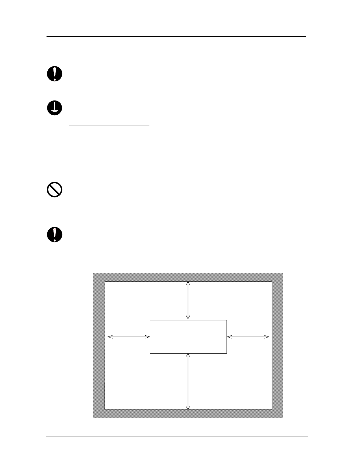
Keep ample space around the equipment to ensure comfortable operation.
(Refer to the following figure.) The floor must be level and the strength must be ample to
sustain the weight of the equipment.
45cm / 18”
or wider
60cm / 24” or larger
when the standard tray is installed
(Rear)
45cm / 18”
or wider
System
(Front)
80cm / 32” or larger
Section 1 Basic Printer Functions 1-2
Page 9

1. 2 Prohibited Originals
To duplicate or copy any type of document is not permitted! It may be illegal if you possess copies
of certain types of documents. We recommend you investigate if you have the legal right to copy /
scan a document prior to performing these functions.
Originals prohibited from copying / scanning (by law)
1. You cannot duplicate/copy Currency (Bill, Money, Bank Note, etc.), Government issued
Negotiable Instruments (National Bonds, Security, Local Debt Bonds, etc.).
2. You cannot duplicate/copy Foreign Currency or Foreign Negotiable Instruments.
3. You cannot duplicate/copy unused postal stamps or government postcards without
permission to replicate from the Government.
4. You cannot duplicate/copy Government issued revenue stamps or certificate stamps, which
are issued by Liquor Tax Acts or the Commodity Tax Acts.
Other Notable Items
1. You are warned by the government not to copy / scan, private issued securities (stock
certificate, draft, check, goods ticket, etc.), commutation ticket or book of tickets, excluding that
some specific companies can copy such originals it requires for its own business.
2. We recommend you not freely copy / scan government issued passports, public or private
issued licenses, automobile inspection certifications, ID and tickets (passes or meal).
Law To Reference Items Prohibited to Duplicate
Regulations to control fake currency and
bonds.
Control Law against Forged or Fake
Foreign Currency, Bill, Bank Note and Bond
Forged postal stamps control law Unused postal stamps or government postcards
Forged revenue stamp control law Government issued revenue stamps, and
Currency similarity securities Control Law Private issued securities (stock, draft, check,
Originals protected by Copyright
It is prohibited to copy / scan:
books, music, paintings, maps, drawings, movie and pictures which are protected
by copyright.
Currency (Bill, Money, Bank Note, etc.),
Government issued Negotiable Instruments
(National Bonds, Security, Local Debt Bonds,
etc.)
Foreign Currency or Foreign Negotiable
Instruments
certificate stamps prescribed by Liquor Tax Act
or Commodity Tax Act
goods ticket, etc.), commutation or book tickets
Section 1 Basic Printer Functions 1-3
Page 10

1. 3 Key Features
The system is a single footprint Multi-Function Printer which can copy, scan and print.
Advanced drivers and comprehensive print utilities make the
system. (some functions may be optional)
The scan and print speeds are up to 60mm/sec or up to 4 landscape “D” prints/minute.
KIP HDP technology generates no waste toner.
The combination of the KIP HDP Plus imaging system with mono-component minute toner
produces high definition lines, distinctive greyscale and consistent blacks.
The maximum paper width is 914mm or 36” wide, and the minimum is 279mm or 11”.The
maximum paper length is 3.6m or 11.8’ (with 36” paper), and the minimum is 210mm or 8.5”.
Up to 600dpi print and scan resolutions, with an advanced Image Process System, produces the
highest quality images.
Copier Features
• Easy Touch screen control panel
• Collated Sets copying
• Real-time image preview
• Recall/reprint previous jobs
• 600x600DPI copy quality
• Integrated Accounting and Reports for all copying, network printing, scanning
• Network ready copier
• Simple Operator assistance for every day tasks (toner replacement procedure)
• Image stamping
• All hardware/software included for instant upgrade from Digital Copier to Network
Printer to Scan-to-File system.
• Information center displays all support information, meter readings, and serial number.
Network Printer Features (Optional)
• Standard TCP/IP connectivity
• Direct support for vector file formats: HPGL1/2, HP-RTL, Calcomp 906/907
DWF format support
•
• Direct support for raster file formats: TIF Group 3/4, Cals Group 4, Uncompressed
Grayscale/Color TIF,
• Optional PDF format support: PS/PDF file format.
• Standard Windows Driver for KIP Script (PS output) and KIP-GL (HPGL/2,RTL output)
• Standard AutoCAD Drivers
• Unlimited site license of KIP Request allows users to group supported formats together
for printing collated sets.
• Integrated Accounting in all KIP Drivers/Request for all network printing.
•
Integrated Web Printing (web server)
• Open architecture ASCII Job Ticket for third party applications
Scan-to-File Features
• Scan directly to PDF, TIF Group 4, Cals Group 4
• Scan to file to FTP or personal inbox on the
• Selected resolution – up to 600 DPI optical
• Automatic original size recognition
• Retrieve scanned image files with KIP Request
system an advanced, easy to use
system
Section 1 Basic Printer Functions 1-4
Page 11

1. 4 Specifications
General
Subject Specification
Model CX8036
Configuration Console
Maximum power
consumption
Acoustic noise Idling Max. 52db
Ozone Max. 0.1ppm (Measurement method under UL Standard)
Dimensions 1240mm (W) x 600mm (D) x 1100mm (H) or
Weight 195 kg or 430 lbs (1 roll)
Environmental condition
for usage
Input power In U.S.A. : 120V plus/minus 10%, 50/60Hz, 10A
NOTE : specifications subject to change without notice
1500W (Including Scanner & IPS)
Printing Max. 60db
Impulse sound Max. 65db
49” x 24” x 44”
(Operation Panel is not included in these dimensions)
200 kg or 440 lbs (2 roll) (weights are estimated)
Temperature:
10 to 32 Centigrade or
50 to 86 Fahrenheit
Humidity:
20 to 85% RH
In Europe : 220-240V plus 6% or minus 10%, 50/60Hz, 6A
Section 1 Basic Printer Functions 1-5
Page 12
Printer
Subject Specification
Model CX8036
Configuration Console – Single Footprint
Printing method LED Array Electro-Photography
Photoreceptor Organic Photoconductive Drum
Print speed 60mm per second
(Metric) 2 A0 / minute
(Inch) 2 E or 4 D Landscape / minute
Print head LED Array – Calibrated
Resolution 600dpi x 600dpi
Print width Maximum 914mm or 36”
Minimum 279mm or 11”
Print length Maximum
(Standard) 3.6m or 11.8’
(Option) 24m or 75’
Minimum 210mm or 8.5”
NOTE
If the page is longer than 3.6m, image quality, function and
reliability are not guaranteed.
Warm up time Less than 5
First print time 24 seconds (D Landscape)
32 seconds (E)
Fusing method Heat - Pressure Rollers
Development method Dry, non-magnetic mono-component toner
Media Plain Paper 64 to 80g/m
2 -
US Bond (20lbs)
Tracing Paper US Vellum (20lbs)
Film 4 MIL
Recommend media for electro-photography process
Storage of consumables Store toner from 0 to 35 C ( 32 to 95 F ) and within the humidity
range from 10 to 85% RH.
NOTE : specifications subject to change without notice
Section 1 Basic Printer Functions 1-6
Page 13

Scanner
Subject Specification
Scanning method Contact Image Sensor (CIS) (5 – A4)
Light source LED
Setting of original Face up
Starting point of scan Center
Scan width Max. : 914.4mm or 36”
Min. : 275.0mm or 11”
Transportable original
width
Scan length Max. : 15,240mm or 50’ (Including the margin area)
Margin area 3mm from leading edge and trailing edge
Optical resolution 600dpi
Digital resolution Max. : 600dpi
Original transportation Sheet through type
Transportable original
thickness
NOTE : specifications subject to change without notice
Max. : 932.2mm or 36.7”
Min. : 275.0mm or 11”
Min. : 210mm or 8.5” (Including the margin area)
Min. : 100dpi
Max. : 0.65mm
Min. : 0.05mm
Section 1 Basic Printer Functions 1-7
Page 14
1. 5 Exterior Views
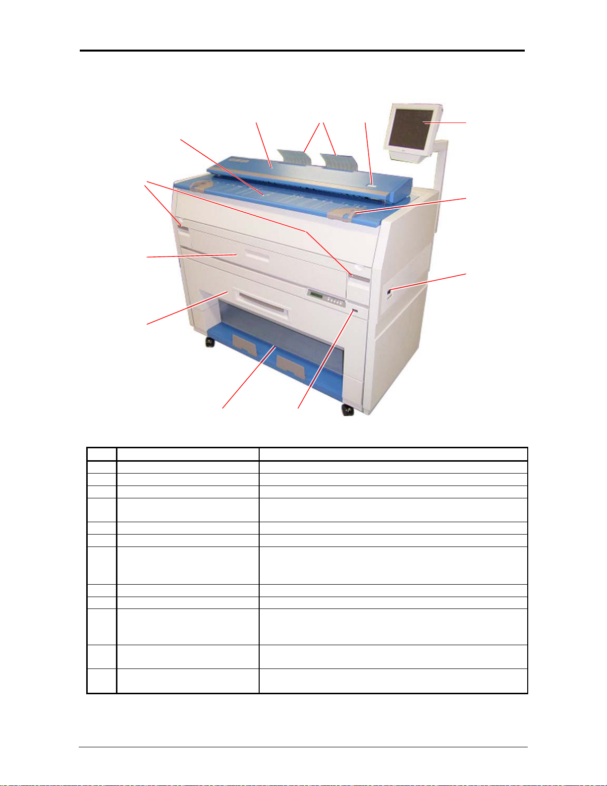
1. 5. 1 Front view
No. Name Function
1 Main Switch Turns on / off.
2 Original Guides Assists the user to feed originals into the scanner.
3 User Interface Operation Panel, with many user operations.
4 Emergency Stop Button Press this button when you would like to stop copying or
5 Original Return Guides Guides return the originals to the user.
6 Scanner Images the original for all scans or copies.
7 Original Table Open this cover to replace the Toner Cartridge.
8 Engine Unit Levers Press up on the handles to open the printer engine.
9 Cut Sheet - Bypass Feeds a sheet of cut sheet media.
10 Roll Deck Roll media installed here.
11 Print Tray Copies / prints are placed here. (standard configuration)
12 Counter Counts the total amount printed.
8
9
10
7
11
6
12
scanning in an emergency situation.
Place the original to feed into the Scanner to make a
scan or copy.
1 Roll - standard
2 Rolls - optional.
Optional Stacking / Folding devices are available
(also see Operational Panel - Info Screen)
45
3
2
1
Section 1 Basic Printer Functions 1-8
Page 15
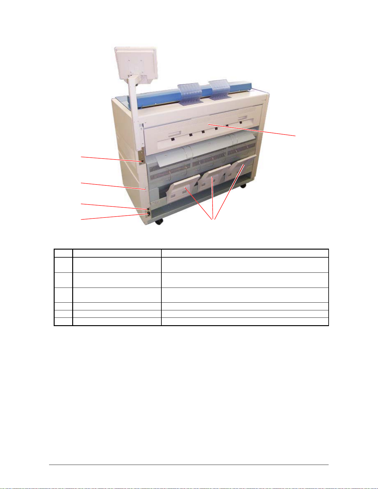
1. 5. 2 Rear view
2
3
4
5
6
No. Name Function
1 Exit Cover Open the Exit Cover when you remove the paper
mis-fed inside of the Fuser Unit.
2 LAN Port Connect the LAN Cable here to connect the system to
the network. (Do not connect a telephone line.)
3 Dehumidify Heater Switch
(Option)
4 Inlet Socket Connect the Power Cord here.
5 Breaker It is possible to shut off supplying the AC power.
6 Print Guide Trays These trays guide the prints to the Print Tray.
Turn on the Dehumidify Heater with this switch when you
would like to dry the paper in the humid season.
1
Section 1 Basic Printer Functions 1-9
Page 16
1. 5. 3 Operator Panel – User Interface Basic Screens
Copy Mode
3
2
No. Name Function
1 Mode Selects the “Mode” of the system. (Copy Mode for this
2 Media Displays Media type and quantity installed. Includes Cut
3 Original Type User Selects the type of original to copy. Also select
4 Quality Select Auto or Manual Image adjustments
5 Copy Count Select the quantity of prints and sets designation.
6 Advanced Settings Invert , mirror, stamps, folds, and edge adjustments
7 Reset Clears the image buffer and resets the system to default
8 View Last The last scan / job can be viewed
9 Recall Job Images can be recalled from the last job for reprint.
10 Interrupt Pauses the network print jobs to print any copy jobs
11 Zoom Manual and automatic zoom ratios set.
12 Log Off Displayed if Accounting enabled to Log off current user
45
6
7
8
9
10
11
12
1
screen shown)
Sheet Functions and Media Selection
Eng/Arch Modes here.
preformed / displayed in this button (sub screen)
settings.
Please note that a time limit may be set to recall or this
feature may be disabled by the administrator to prevent
any unauthorized copies.
Section 1 Basic Printer Functions 1-10
Page 17
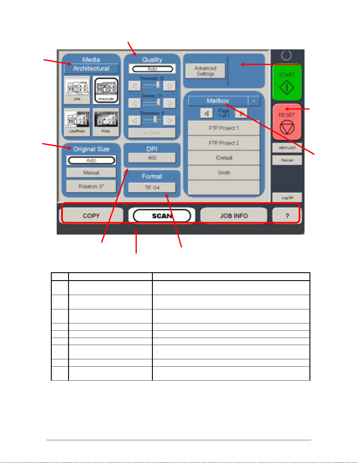
Scan Mode
4
2
3
7
8
9
No. Name Function
1 Mode Selects the “Mode” of the system. (Scan Mode for this
2 Original Size Use automatic settings or manually set width, length and
3 Original Type User Selects the type of original to copy. Also select
4 Quality Select Auto or Manual Image adjustments
5 Resolution Scroll through image resolution (DPI) of the scanner.
6 Format Scroll through file formats.
7 Advanced Settings Invert, mirror, stamps, and edge adjustments preformed
8 Reset Resets the system to default settings.
9 Mailbox Select where the image will be stored after the scan
5
6
1
screen shown)
rotation of the images.
Eng/Arch Mode selected here.
/ displayed in this button (sub screen)
(local setting, FTP etc.).
Section 1 Basic Printer Functions 1-11
Page 18
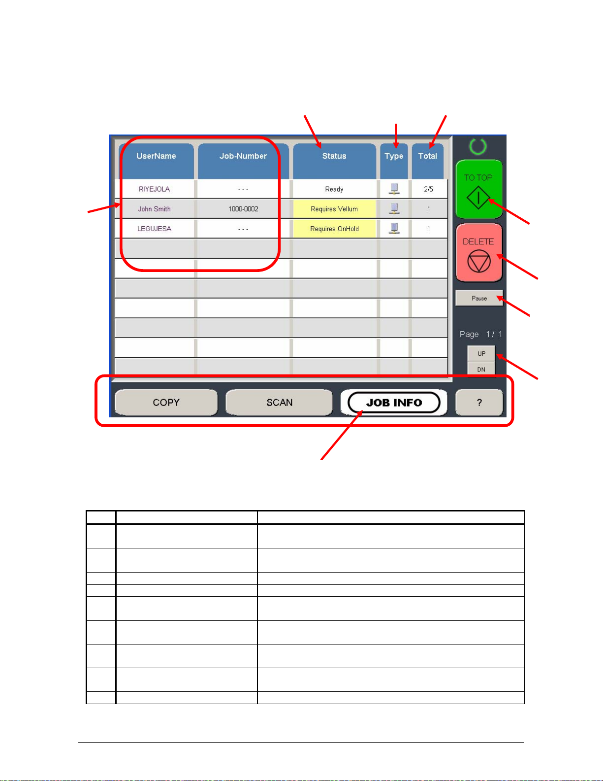
Job Info Screen
2
No. Name Function
1 Mode Selects the “Mode” of the system. (Job Mode for this
screen shown)
2 User Name – Job # Display the User and any user info of the job ID. A job
can be selected for other functions noted below.
3 Status Shows the current status of a job and media selection.
4 Type Displays a copy or network print job
5 Total Displays the total number of prints and current number
printed.
6 To Top After a job is selected (see #2) the position can be
changed to the next job printed.
7 Pause Pauses printer to allow media change, etc
3
1
4
5
6
8
7
9
8 Delete After a job is selected (see #2) it can be removed from
printing.
9 Up/Down Scrolls through available pages in the queue.
Section 1 Basic Printer Functions 1-12
Page 19
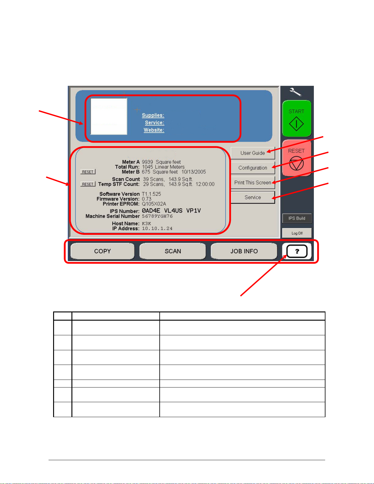
Information / Help Screen
3
2
No. Name Function
1 Mode Selects the “Mode” of the system. (Info/Help Mode for
2 Meter – Versions Display the current meter counts as well as all
3 Contact Shows the contact information for the Service and
4 User Guide User Guides for details on system functions and
5 Configurations Allows user “set up” of the system.
6 Print This Screen Allows the current screen with version and counter
7 Service Allows advanced “set up” of the system. Usually for
1
this screen shown)
Software/Firmware versions, IPS number, Host Name/IP
Supplies provider.
operations.
values to be prin
technical purposes only. Pass-code required.
ted on the system.
4
5
6
7
Section 1 Basic Printer Functions 1-13
Page 20

1. 6 Options - Accessories
Please contact your Authorized Reseller for the following options available:
1) Network Printing
Adds the functions of network printing (TCP/IP) from Windows and CAD applications. Includes
Windows/PS drivers, AutoDesk Drivers, “Request” job submission utility and “KIP PrintNet” for
web based submissions.
2) Scanning
Adds the function of scan to file, local drives or FTP sites in a variety of file formats.
3) PDF / PS Printing
Allows direct PDF and Postscript file format printing from various applications including
Request.
4) Roll Deck 2
Second roll of media for increased productivity
5) Print Trays - Slant Stacker
To accommodate a larger quantity of prints than the standard front print tray rearward stacking
systems are available
6) Folding (KIPFold)
For fan and crossfold functions as a copier, or network printer.
7) Dehumidifier
Roll Deck Dehumidifier for locations with excess or high humidity
options and accessories are subject to change without notice. Please contact your
All
local Authorized Reseller for details on current available options
.
.
Section 1 Basic Printer Functions 1-14
Page 21
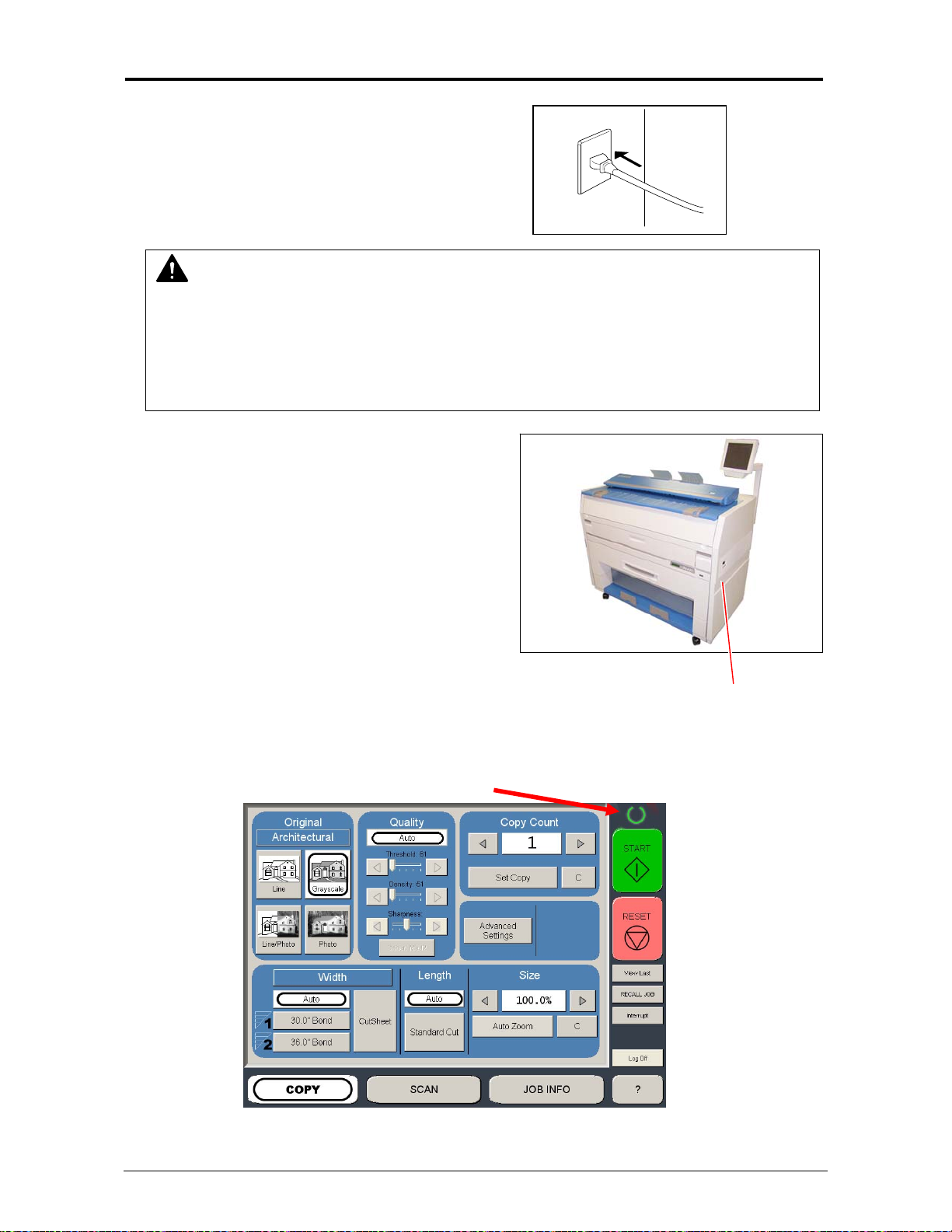
2. 1 Turning on
1. Ensure the
wall outlet.
WARNING
(1) Do not handle the Power Plug with wet hands, or you may receive an electrical shock.
(2) Make sure to ground the machine for your safety.
(3) Do not plug the printer into a multi-plug connector in which other devices are
plugged into. It may overheat the outlet and may result in a fire.
(4) The outlet must comply with 120V, plus 6% & minus 10%, 15A, and 50/60Hz
2. There is a Power Switch on the right side of
system.
Switch to the “ I ” position to turn
Power Switch
3. The Operation Panel commences to operate, and the Copy Mode Screen will appear in
approximately 1 minute. A Ready Indicator on the Copy Mode Screen will flash during the
warm up process.
Ready Indicator
4. When the Ready Indicator stops flashing, the
system is plugged into a dedicated
on the system.
system is ready to copy/scan/print.
Section 1 Basic Printer Functions 1-15
Page 22
2. 2 Turning off
1. There is a Power Switch on the right side of
system.
Switch to the “ O ” position to turn off the
system.
Power Switch
2. 3 Roll Media Replacement
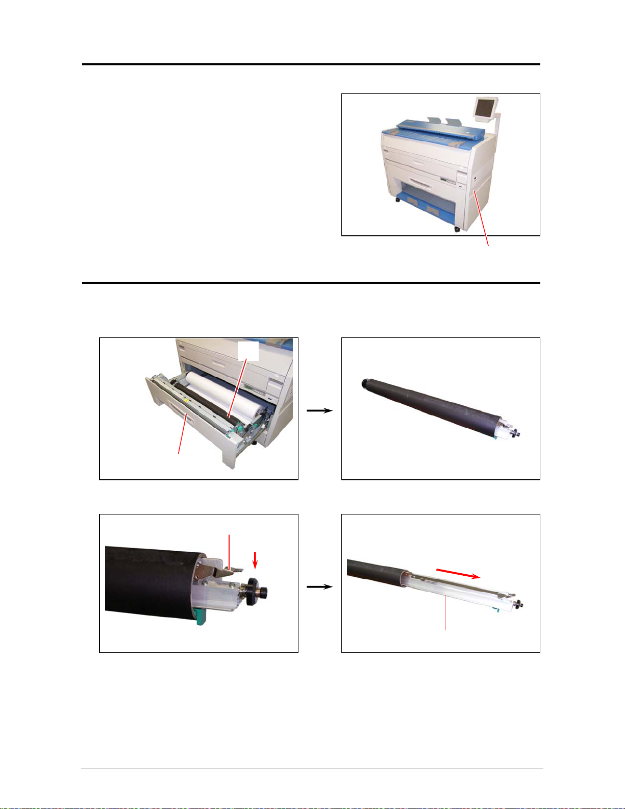
1. Open the Roll Deck (1).
Remove the Spool (2) with the roll core from the Roll Deck.
2. Press down on the Lever (3) to release the core, and then pull out the Spool (2) from
the core.
1
2
3
2
Section 1 Basic Printer Functions 1-16
Page 23
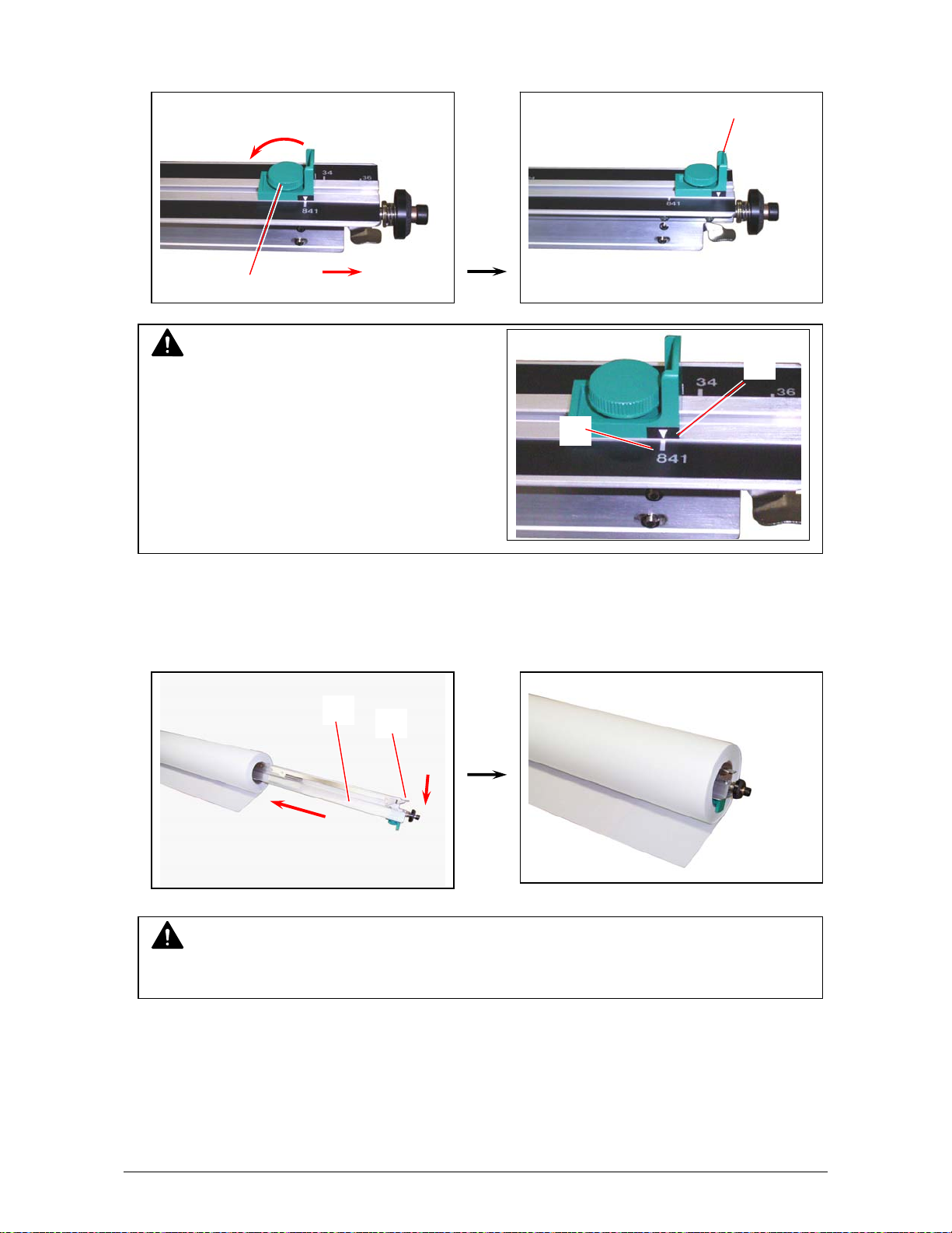
3. If so required, loosen the knob (4), slide the position of Paper Guide (5) according to the width
of media to be installed, and then secure the Paper Guide by tightening the knob.
NOTE
There are Size Guides (6) on the Spool.
The Paper Guide is provided with a triangle mark
(7), place the Paper Guide so that
the triangle aligns with the line of Size Guide.
4. Place a new roll on a table/desk or another stable flat surface. Pressing down the Lever (3),
insert the Roll Spool (2) into the core of new roll.
NOTE
Please note the unwinding direction of the media at this time. Please see diagrams.
4
6
2
3
5
7
Section 1 Basic Printer Functions 1-17
Page 24
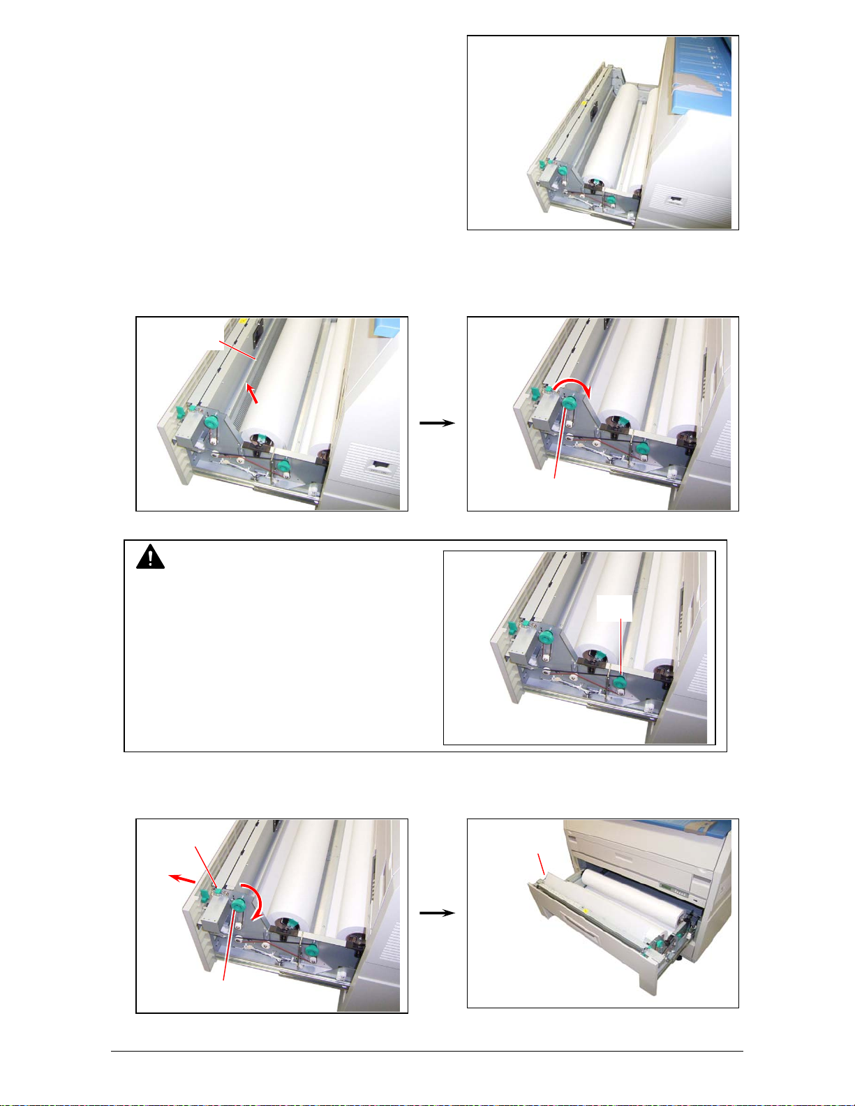
5. Place the Spool with new roll into the Roll Deck.
6. Insert the leading edge of the media under the Guide Plate (8) until the edge touches
the feeding roller.
Then rotate the Feeding Handle (9) clockwise so that the feeding rollers catch the roll
paper.
8
9
NOTE
In case of Roll 2, rotate the Feeding Handle
of Roll 2 (10).
10
7. When the feeding rollers catch the media, move the Lever (11) to the front side and rotate the
Paper Feeding Knob (9) until the leading edge comes out from the guides.
11
Leading edge
of roll paper
9
Section 1 Basic Printer Functions 1-18
Page 25
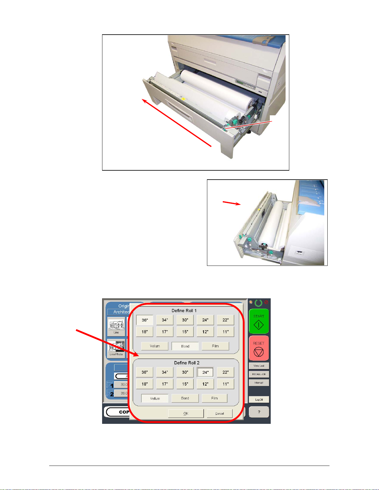
8. Slide the Cutter Handle (12) fully from one side to another side to cut the leading edge.
Remove the cut portion and discard.
10. Close the Roll Deck.
11. On the Operator Panel, a screen will automatically appear after the deck is closed to define the
media width and type. Please select the width, and type for each roll deck and then select the
“OK” button to confirm the selection.
12
Section 1 Basic Printer Functions 1-19
Page 26
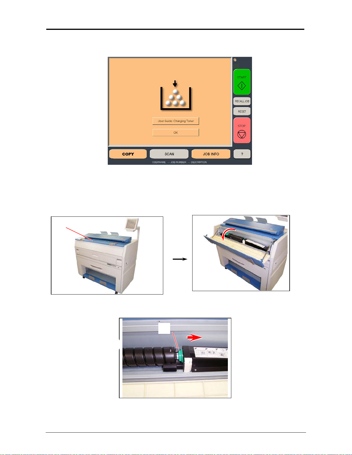
2. 4 Toner Installation
When toner installation is required, the Operator Panel will display a “Toner Required” screen
(in the “Copy” and “Job Info” Screens)
To replace the toner cartridge, please follow these steps:
Please note that the replacement procedure can also be displayed on the Operator Panel for
easier access, by pressing “User Guide : Changing Toner” on the screen)
1. Open the Toner Cover (1).
1
2. Slide the green Disk (2) to the right, to unlock the Toner Cartridge.
2
Section 1 Basic Printer Functions 1-20
Page 27
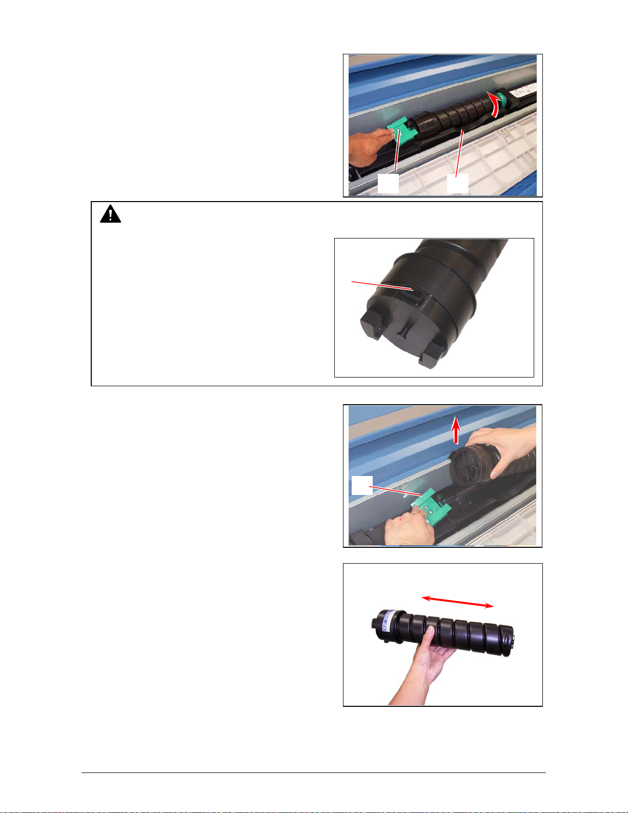
3. Pressing down on the Cartridge Lock Lever (3),
rotate the body of cartridge (4) in the arrow
direction several revolutions until it stops turning.
The cartridge is resealed by this procedure!
NOTE
If you remove the Toner Cartridge without
resealing the toner outlet (5) the toner
will drop from the toner outlet and it will
scatter into the machine or onto the floor!
4. Pressing down the Cartridge Lock Lever (3), lift
up on the left side of the Toner Cartridge, and
then remove the entire cartridge from the machine.
Discard the spent cartridge using local recycling
or waste management programs.
5. Shake a new Toner Cartridge several times from
left and right to loosen the toner.
3 4
5
3
Section 1 Basic Printer Functions 1-21
Page 28
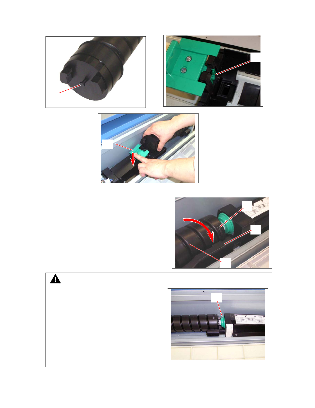
6. Locate the pin (6) of the left side of cartridge. While pressing down the Cartridge Lock Lever (3),
fit the pin to the groove (7)
7
6
3
7. Rotate the body of the cartridge (4) to the arrow’s
direction, several revolutions to open the toner
8
outlet.
Confirm that the projection (8) will fit into the
notches (9).
9
4
NOTE
It is not necessary to lock the cartridge with the
green Disk (2).
It will automatically lock after the
Toner Hatch is closed.
2
Section 1 Basic Printer Functions 1-22
Page 29
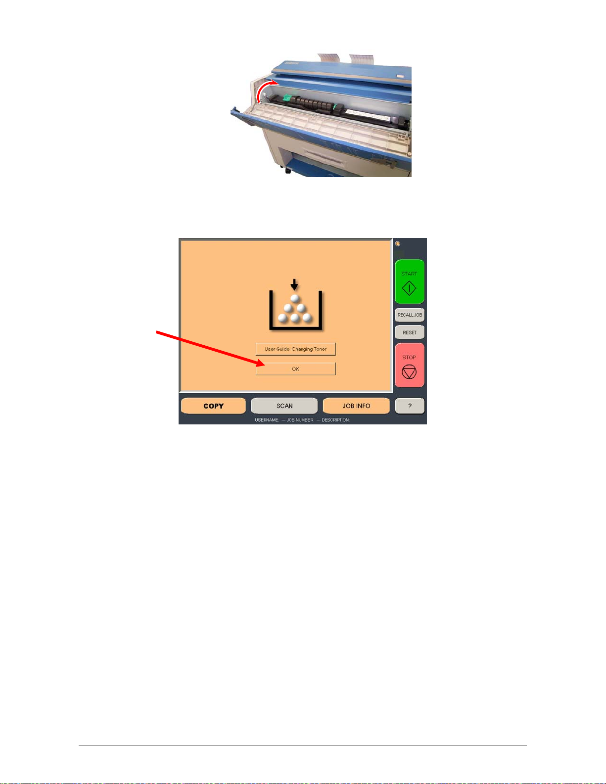
8. Close the Toner Cover.
9. Press “OK” on the Operator Panel to continue copying or printing.
Section 1 Basic Printer Functions 1-23
Page 30

2. 5 Cut Sheet Media Placement
1. Select Cut Sheet Bypass Button on the Operator Panel. (Copy Mode)
2. Select the size of the sheet, and the media type (not shown)
3. Or use “Custom” to select a width.
Section 1 Basic Printer Functions 1-24
Page 31

4. Select a standard length or use a “Custom Length”.
5. Confirm the cut sheet size by pressing enter.
6. Open the Cut Sheet Feeder (1).
1
Section 1 Basic Printer Functions 1-25
Page 32

6. There are size markings on the table.
Insert the cut sheet paper on the table along with the associated size mark, and then insert
it into the Feeder referencing the size marks.
When the paper is inserted far enough, the machine automatically sets the paper at the
proper position.
7. Continue with normal copy / print functions. See User Guide “Copy” or “Print” sections.
2. 6 Emergency Stop of a Copy or Scan
If ever so required, press the Stop Button (1) on the Scanner to immediately stop the original while
making a copy or a scan.
1
Section 1 Basic Printer Functions 1-26
Page 33

2. 7 Dehumidifying the Roll Media
If the printer is located in an environment where the humidity may effect the image quality, please
turn on the dehumidifiers.
1. Select Switch to “ I “ position
Dehumidifier switch
Dehumidifiers are an option for the
details.
NOTE
system. Please contact you local dealer for
Section 1 Basic Printer Functions 1-27
Page 34

3. 1 Operational Errors
3. 1. 1 Paper mis-feed Errors
In case of a paper jam, a message will be displayed on the Operator Panel as well as the
Technical LCD. One of the following messages will be displayed if an error does occur.
Roll Deck / Feeding Jam
Cut Sheet / Manual Jam
Internal Jam Resist Jam
Fuser Jam
Accessory Jam
3. 1. 1. 1 Deck jam / Feeding Jam
Either “Deck jam” or “Feeding Jam” is displayed when the roll paper is mis-fed in the Roll Deck.
1. Open the Roll Deck, and unwind the roll paper.
2. Insert the leading edge of media under the under the Guide Plate (2) until the edge touches
the feeding roller.
Then rotate the Feeding Knob (3) clockwise so that the feeding rollers catch the roll
paper.
2
3
Section 1 Basic Printer Functions 1-28
Page 35

NOTE
In case of Roll 2, rotate the Feeding Knob
of Roll 2 (4).
4
3. When the feeding rollers catch the paper, move the Lever (5) forward and rotate the
Feeding Knob (3) until the leading edge comes out from the guides.
5
Leading edge
of roll paper
3
4. Slide the Cutter Handle (6) fully from one side to another side to cut the media.
Remove the cut media.
6
Section 1 Basic Printer Functions 1-29
Page 36

3. 1. 1. 2 Cut Sheet / Manual Paper Jam
1. Carefully remove the paper by pulling as noted.
3. 1. 1. 3 Resist Jam / Internal Jam
1. Pull up the Engine Levers (1) to open the printer.
1
2. Remove any mi-fed paper.
Section 1 Basic Printer Functions 1-30
Page 37

3. 1. 1. 4 Fuser Jam
1. Open the Fuser Cover (1).
2. Remove the jam paper, by carefully pulling out the
back.
WARNING
There are extremely hot parts inside of the Heater Area.
Do not touch any parts in the Heater Unit, or you will be burnt!
Also note that the paper may be very hot as well.
NOTE
If you can not find the mis-fed paper inside of the Fuser, refer to [3. 1. 1. 3 Resist Jam /
Internal Jam] and follow the instructions.
1
3. 1. 1. 5 Optional Finisher Jam
The media is mis-fed in the optional finishing device such as a Stacker or Folder.
Remove the mis-fed paper referencing the User Guide of optional device.
Section 1 Basic Printer Functions 1-31
Page 38

3. 1. 2 Others
3. 1. 2. 1 Deck is open
This message is displayed when the Roll Deck is
opened.
Reopen and then close it firmly.
3. 1. 2. 2 Optional Finisher Jam
The media is mis-fed in the optional finishing device such as a Stacker or Folder.
Remove the mis-fed paper referencing the User Guide of optional device.
3. 1. 2. 3 Cut Sheet / Manual Set NG
This message is indicated when cut sheet media
has been set before the system is turned on.
Remove media from the Cut Sheet Feeder.
3. 1. 2. 4 Cutter Set NG
This message is indicated when the Cutter Knob is not in the correct position.
Open the Roll Deck, and then slide the Cutter Knob fully to the left or right until it stops.
Not correct (Not at the end) Correct (at the end)
Cutter Knob Cutter Knob
Roll Deck
Cut Sheet
Feeder
Section 1 Basic Printer Functions 1-32
Page 39

3. 1. 2. 5 Toner Empty
This message is indicated when the Toner Cartridge is
empty with the toner.
Replace the Toner Cartridge referencing
[2. 4 Replacement of Toner Cartridge]
3. 1. 2. 6 Paper Empty
This message is indicated when the roll paper is empty.
Replace media referencing
[2. 3 Replacement of Roll Paper].
3. 1. 2. 7 The door opened during printing
This message is indicated when the Roll Deck is opened
for some reason in the middle of printing.
Close the Roll Deck.
The paper usually will be mis-fed inside the
machine, please remove it.
Toner Cartridge
Roll paper
Roll Deck
Section 1 Basic Printer Functions 1-33
Page 40

3. 2 Call Service Errors
If the machine has the fatal error you will note one of the following Error Codes on the Technical
LCD panel. It is impossible for the user to resolve these errors.
PLEASE CONTACT YOUR
TO RESOLVE THESE ERRORS.
Code Error
E - 000 Fuser Low Temp
E - 001 Fuser Over Temp
E - 002 Fuser Low Temp
E - 003 Temp Not Rise
E - 010 Motor1 Error
E - 011 Motor2 Error
E - 012 Motor3 Error
E - 020 Counter Error
E - 031 1st Error
E - 032 AC Error
E - 033 Tr Error
E - 034 Bias Er ror
E - 040 Cutter Error
E - 050 FPGA Error
E - 070 Dev Error
If any of the above errors is displayed:
1. Turn off the printer, wait approximately one minute, and turn the printer on again.
2. If the same error code is displayed, turn off the printer, and then unplug the printer from the
wall outlet.
3. Contact your Authorized
Service Company.
AUTHERIZED SERVICE PERSONNEL
Section 1 Basic Printer Functions 1-34
Page 41

Section 2
Copy Mode
1. 0 Copy Mode............................................................................................................................ 3
1.1 Main Screen - General .................................................................................................... 3
1.2 Simple Copying............................................................................................................... 4
1.2.1 Select Copy Mode ....................................................................................................... 4
1.2.2 Select Size Mode ......................................................................................................... 4
1.2.3 Select Original Image Type ........................................................................................ 5
1.2.4 Cop y Count..................................................................................................................5
1.2.5 Media ............................................................................................................................ 6
1.2.6 Length .......................................................................................................................... 6
1.2.7 Size ...............................................................................................................................7
1.2.8 Insert Original..............................................................................................................7
2. 0 Operation Details.................................................................................................................8
1.3 Main Screen..................................................................................................................... 8
1.4 Original............................................................................................................................. 8
1.4.1 Original Size Mode ...................................................................................................... 8
1.4.2 Original Type ............................................................................................................... 9
1.5 Quality..............................................................................................................................9
1.5.1 Automatic.....................................................................................................................9
1.5.2 Threshold...................................................................................................................10
1.5.3 Density ....................................................................................................................... 10
1.5.4 Sharpness..................................................................................................................10
1.5.5 Dither..........................................................................................................................10
1.6 Copy Count....................................................................................................................10
1.6.1 Arrows - Count Increase / Decrease....................................................................... 11
1.6.2 Number Pad - Count Increase / Decrease............................................................... 11
1.6.3 Set Copy..................................................................................................................... 11
1.6.4 Clear ........................................................................................................................... 12
1.7 Advanced Settings.......................................................................................................13
1.7.1 Mirror..........................................................................................................................13
1.7.2 Invert........................................................................................................................... 13
1.7.3 Fold............................................................................................................................. 13
1.7.4 Stamp ......................................................................................................................... 14
1.7.5 Leading Edge Adjustment........................................................................................15
1.7.6 Trailing Edge Adjustment......................................................................................... 16
1.8 Width .............................................................................................................................. 16
1.8.1 Auto ............................................................................................................................ 17
1.8.2 Manual Roll Selection ............................................................................................... 17
1.8.3 Enabling Cutsheet..................................................................................................... 18
1.8.4 Cut Sheet.................................................................................................................... 18
1.8.5 Copying to Multiple Cutsheets.................................................................................19
1.8.6 Media Remaining....................................................................................................... 20
1.8.7 Installing Roll Media..................................................................................................20
1.9 Length ............................................................................................................................ 21
1.9.1 Auto ............................................................................................................................ 21
1.9.2 Standard..................................................................................................................... 21
1.10 Size – Zoom ................................................................................................................... 23
1.10.1 Preset Percentages...............................................................................................23
1.10.2 Percentage Key Pad.............................................................................................. 24
1.10.3 Page Size Zoom..................................................................................................... 24
Section 2 Copy Mode 2-1
Page 42

Auto Zoom ............................................................................................................. 25
1.10.4
1.10.5 Clear ....................................................................................................................... 26
1.11 Start................................................................................................................................26
1.12 View Last.......................................................................................................................26
1.13 Recall Job .....................................................................................................................26
1.14 Stop / Reset ................................................................................................................... 26
1.15 Interrupt ........................................................................................................................ 26
1.16 Rescan ........................................................................................................................... 27
1.17 Log Off ........................................................................................................................... 27
Section 2 Copy Mode 2-2
Page 43

1. 0 Copy Mode
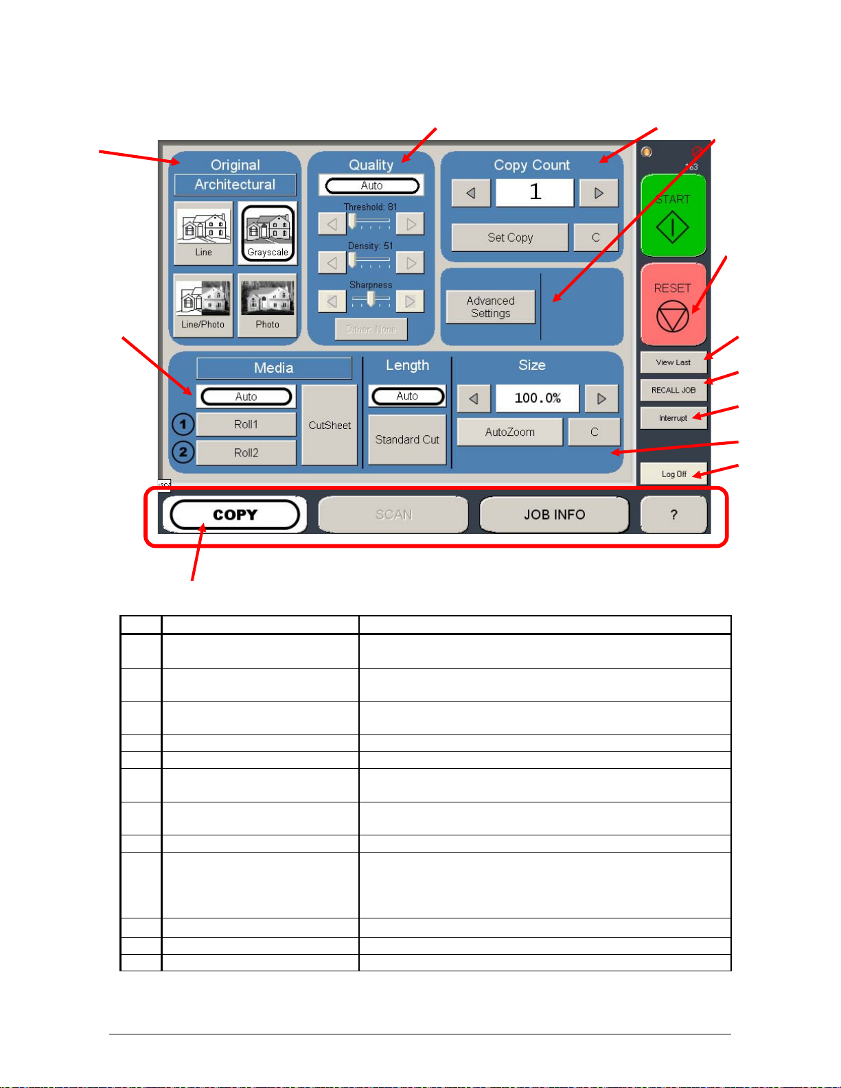
1.1 Main Screen - General
3
2
No. Name Function
1 Mode Selects the “Mode” of the system. (Copy Mode for this
2 Media Displays Media type and quantity installed. Includes Cut
3 Original Type User Selects the type of original to copy. Also select
4 Quality Select Auto or Manual Image adjustments
5 Copy Count Select the quantity of prints and sets designation.
6 Advanced Settings Invert , mirror, stamps, folds, and edge adjustments
7 Reset Clears the image buffer and resets the system to default
8 View Last The last scan / job can be viewed
9 Recall Job Images can be recalled from the last job for reprint.
10 Interrupt Pauses the network print jobs to print any copy jobs
11 Zoom Manual and automatic zoom ratios set.
12 Log Off Displayed if Accounting enabled to Log off current user
13 Length Sets the length of the copy
1
4
13
screen shown)
Sheet Functions and Media Selection
Eng/Arch Modes here.
preformed / displayed in this button (sub screen)
settings.
Please note that a time limit may be set to recall or this
feature may be disabled by the administrator to prevent
any unauthorized copies.
5
6
7
8
9
10
11
12
Section 2 Copy Mode 2-3
Page 44

1.2 Simple Copying
To copy, pl ease follow these basic steps. The following chapters have details on
adjustments and parameters that the user can change to modify the copies as required.
1.2.1 Select Copy Mode
On the lower region of the Operator Panel select “COPY”.
1.2.2 Select Size Mode
Select whether the document is an engineering or architectural size document. This will
allow the automatic width detection to function.
Engineering widths = 34, 22, 17, 11, and 8.5 inches
Architecture widths = 36, 30, 24, 18, 12, and 9 inches
Section 2 Copy Mode 2-4
Page 45

1.2.3 Select Original Image Type
Set the original image type you will copy. The selections are:
Line - used for simple line documents
Line / Photo - used for a combination of lines & photos documents
Greyscale - used for a combination of lines & areas of shade (CAD) originals
Photo - used for photographic originals
This will allow automatic image quality adjustments for the scan.
1.2.4 Copy Count
Press the arrow buttons to scroll through the number of copies required or press on the
actual number to set the quantity with the number pad.
Section 2 Copy Mode 2-5
Page 46

1.2.5 Media
Selects automatic (for best possible fit) or manual roll selection.
or
1.2.6 Length
Select Auto for automatic cut length (to the length of the original) or Standard Cut for a
manual length. (a number pad will request the desired length to be entered)
Section 2 Copy Mode 2-6
Page 47

1.2.7 Size
Select
a) AutoZoom to automatically zoom to the width of paper or
b) press the arrow keys to scroll through presets ratios or
c) press on the Zoom number to enter a ratio on the key pad
1.2.8 Insert Original
Using the guides on the feed table, center the
original face up and insert the document.
Continue to push forward until the scanner accepts
the document.
The original will automatically commence to copy. While this occurs the image will be
displayed on the Operator Panel for your reference.
Section 2 Copy Mode 2-7
Page 48

2. 0 Operation Details
1.3 Main Screen
The main Copy screen is selected with the Copy Button.
It contains all user functions for copying. The following pages details the functions and
settings of each button and sub screens that can be used to adjust the copy mode
parameters to achieve the required result.
1.4 Original
This region allows the setting of the Size Mode (Engineering or Architectural) and the
original image type.
1.4.1 Original Size Mode
This button is used to select the Size Mode of Engineering or Architectural .
This will allow the automatic width detection system to determine the image width when an
original is placed in the scanner.
Engineering widths = 34, 22, 17, 11, and 8.5 inches
Architectural widths = 36, 30, 24, 18, 12, and 9 inches
Section 2 Copy Mode 2-8
Page 49

1.4.2 Original Type
There is a selection of four different predetermined original types. The selections are:
a) Line - used for simple line documents
b) Line / Photo - used for a combination of lines & photos documents
c) Greyscale - used for a combination of lines & areas of shade (CAD)
originals
d) Photo - used for photographic originals
Press the desired original setting from one of the four diagrams. This will allow automatic
image quality adjustments for the next scan. Please note that the selection will be
highlighted with a “black circle” and the icon will become white, as in the above example
“Greyscale”
1.5 Quality
This region is used to change the image quality settings from the automatic setting.
1.5.1 Automatic
For most copies, “Auto” should be selected. This will allow the copier to automatically
determine the best image settings without any user intervention (please also note
“Original” in 2.2)
Section 2 Copy Mode 2-9
Page 50

1.5.2 Threshold
To override the “Automatic” setting, “Threshold” can be adjusted.
Deselect “Auto” to enable “Threshold”.
When the arrows are pressed the threshold will be set to a desired
level. This will suppress or enhanc e the lines and images on the
original.
1.5.3 Density
To override the “Automatic” setting, “Density” can be adjusted.
Deselect “Auto” to enable “Density”.
When the arrows are pressed the background density will be set to
a desired level. This will suppress or enha nc e the background of
the original.
1.5.4 Sharpness
To override the “Automatic” setting, “Sharpness” can be adjusted.
Deselect “Auto” to enable “Sharpness”.
When the arrows are pressed the line sharpness will be increas ed
to remove rough lines or decreased when photos are copies to
allow smoother graduations.
1.5.5 Dither
To override the “Automatic” setting, “Dither” can be adjusted. Deselect “Auto” to enable
“Dither”.
By pressing the dither button,
a) None
b) Fine
c) Medium or
d) Course
dither of the image can occur. This will change how the dots are
arranged to create the final image of the copy. For fine lines a
“Course” dither pattern may be desired. For Photos “None” may be
desired.
1.6 Copy Count
In this region the number of copies, and set copy / collation can be set.
Section 2 Copy Mode 2-10
Page 51

1.6.1 Arrows - Count Increase / Decrease
Use the arrows to increase or decrease the total numbers of copies desired by one with
each press of the button.
In this example the arrow was press seven times to reach “8 copies”.
1.6.2 Number Pad - Count Increase / Decrease
Press the ”number of copies” value (which is a button) to set the desired number of copies
using a number pad. This will allow the quicker entry of the desired quantity if a larger
number is desired.
a) Press the numbers for the quantity
desired. (up to 999)
b) Select “Enter”
c) If an entry error was made press “C” to
start again
d) If you wish to close the screen without
changing the quantity press “Cancel”.
1.6.3 Set Copy
a) To enable collated sets or copy sets to be printed select the Set Copy button.
b) As originals are scanned , the total number in the set are displayed.
Section 2 Copy Mode 2-11
Page 52

c) Copying will not commence until the set is closed. To close a set, press the start
button. The set with the total number of copies will be printed.
An example of Set Copy:
3 originals with 3 sets or copies
1 2 3
Originals
.
Copies
1.6.4 Clear
Press the clear button to reset the quantity to “1”.
Section 2 Copy Mode 2-12
Page 53

1.7 Advanced Settings
The Advanced Setting button contains the additional
parameters on a sub screen:
a) Mirror
b) Invert
c) Fold (if optional device connected)
d) Stamp (Water Mark)
e) Lead Edge Adjustment
f) Trail Edge Adjustment
When any of the adjustments / selections are selected, the selections will now b e
displayed on the main Copy screen
1.7.1 Mirror
Select this button to “mirror” a scan. This can be utilized on originals that
may have the actual image on the reverse side such as older “sepia” or
“film” documents.
1.7.2 Invert
Select this button to change a region of white to black and visa versa of a
scanned document. This is normally used for “negative” documents or
“blue prints”.
1.7.3 Fold
Select “Fold” to display another sub screen. This will allow the selection of a “Fold Pattern”
to be applied to the copy.
a) use the Arrow buttons to scroll through the
available folds and then select the fold
from the list.
Section 2 Copy Mode 2-13
Page 54

b) The fold selected will be displayed in the button.
c) Select OK
NOTE
The list of “Folds” are loaded into Copy Mode by the
system administrator or key operator. They can not be
altered or modified in any manner on the
Operator Panel.
Please contact these persons for any additional stamps
that may be required.
Please see “KIP Request” for these functions.
An optional KIP Folder must be purchased to enable
these functions.
system
1.7.4 Stamp
Select “Stamp” to display another sub screen. This will allow the selection of a “Stamp” or
“Water Mark” to be placed on the scanned image. It will be imbedded into the image.
a) use the Arrow buttons to scroll through
the available stamps and then select the
stamp from the list.
b) The Stamp button will now display the stamp selected.
c) Select OK
Section 2 Copy Mode 2-14
Page 55

NOTE
The list of “Stamps” are loaded into Copy
Mode by the system administrator or key
operator. They can not be altered or
modified in any manner on the
Operator Panel.
Please contact these persons for any
additional stamps that may be required.
Please see “KIP Request” for these
functions.
system
1.7.5 Leading Edge Adjustment
The leading edge of a copy can be altered. ( +/- 4” )
a) additional void area can be placed on the lead edge of a scan or
b) image can be removed (such as a binding strip or a file hanger)
Leading Edge + Leading Edge -
Image
Scanner
Image
Scanner
Image
ScannerImage
Copy
Original
Scanner
Copy
Deleted image
Added margin
Original
To adjust the Leading Edge, use the arrows to denote the quantity you wish to add or
remove.
Section 2 Copy Mode 2-15
Page 56

1.7.6 Trailing Edge Adjustment
The trailing edge of each copy can be altered. ( +/- 4” )
c) additional void area can be placed on the bottom of a copy or
d) image can be removed (such as a binding strip or a file hanger)
Scanner
Image
Original
Trail edge + Trail Edge -
Image
Scanner
Copy
Deleted trailing image
Added trailing margin
Image
Scanner
Original
Image
Copy
1.8 Width
This region allows automatic or manual roll selection, roll size display, cut sheet media, the
roll amount remaining and to set the installed media type and width.
Section 2 Copy Mode 2-16
Page 57

1.8.1 Auto
This default setting allows the copier to automatically select the best media roll width to
print the image onto. It selects the roll noting the amount of image area to prevent surplus
media consumption. (applies to the option - two roll model)
Example:
22” original
36” and 24” bond media installed
Original is 22” wide
36” installed 24” Installed
excess non-imaged media has the best image to media fit
therefore this roll will be used
1.8.2 Manual Roll Selection
To select a roll deck. press the roll deck desired. Note that the roll information is displayed
in the roll deck button.
Section 2 Copy Mode 2-17
Page 58

1.8.3 Enabling Cutsheet
system is equipped with a cut sheet feeder that can be enabled in the configuration
The
of the user interface.
menu
This can be accomplished by following these steps
1. Select the (?) button in the bottom left corner of the user
interface.
2. Select the Configuration button from the Info/Help screen
3. Using the Left/Right arrows located at the bottom of the
page
scroll to page three (3).
4. From the Enable Cut Sheet “Yes” button.
1.8.4 Cut Sheet
To copy onto a cut sheet of media:
a) Select the CUT SHEET button on the main screen.
b) Select the Output Size of the actual cut sheet paper that will be inserted into the Cut
Sheet feeder.
Select desired settings from the main copy screen. Feed your original (s) into the
scanner.
Section 2 Copy Mode 2-18
Page 59

c) Open the Cut Sheet Feeder (1) and WAIT
until prompted by
the UI to
insert the Cut Sheet media.
1
d) There are size markings on the table.
Line up the original cut sheet on the feed table with the associated size marks.
When the paper is inserted far enough, the machine automatically sets the paper at
the proper position.
1.8.5 Copying to Multiple Cutsheets
1. Follow 1 through of the steps above (1.8. 4)
2. After a short period of time the Printer will beep notifying the user to insert the
cutsheet into the Cutsheet feeder, the Job Info button will also be flashing.
3. Once the cutsheet has been printed there will be a short pause and the printer will
start to beep again. Insert the next cutsheet into the printer
4. Continue for multiple s.
Note:
Only one cutsheet may be fed at a time and will time out after 3 minutes if no paper is
inserted.
Note:
DO NOT insert the cut sheet media into the feeder while printing from a roll deck, as this
may cause the printer to jam.
Section 2 Copy Mode 2-19
Page 60

1.8.6 Media Remaining
The installed roll information is displayed in the button of the particular roll deck. Beside
each deck is a volume of media that currently is left on the roll of media.
Indicators will display full, 3/4 ,1/2, 1/4 or empty
1.8.7 Installing Roll Media
When media is replaced or installed, a screen will automatically appear. This screen
allows the setting of the media type and width. Please see the BASIC PRINTER
FUNCTION ( Section 1 ) for the procedures to replace a roll of media.
a) if no changes are required, press cancel
b) if changes are required from the currently settings displayed, select the correct
media type and size for each deck and press OK.
This screen shows 36” bond for
deck one and 18” Vellum for deck two
Media types settings noted above can be changed at any time by pressing the Media
button on the main Copy Screen.
Section 2 Copy Mode 2-20
Page 61

1.9 Length
Two methods determine the length of the copy. These two methods are
Auto (may also be known as Syncro Cut or Automatic Cut ) and Standard Cut.
1.9.1 Auto
This mode allows the media length to be determined by the original
length. This also takes into consideration any enlargements or
reductions that are applied to an image as well, to prevent excess
media without image.
NOTE
Auto Length works in conjunction with Auto Roll
noted in 2.6.1.
1.9.2 Standard
This mode allows the media length to be determined by a standard length or a length set
manually by the user with a number pad.
a) select Standard Cut. A sub screen will appear. When Standard is used, the roll
must also be determined.
- If Auto Roll is selected in the Media region the following screen will appear,
prompting the media to be selected. Select the roll.
Section 2 Copy Mode 2-21
Page 62

- If a roll is already selected in Media, then the following screen appears now only
requesting the length.
b) Once the roll is determined (if so required)
the length can now be set.
- Standard Length
- Auto Length
- Custom Length
c) Standard Length – use an industry standard
length. Select the length and press Enter.
d) Auto Length – uses the length of the
original to determine the copy length.
Select and press Enter
Section 2 Copy Mode 2-22
Page 63

e) Custom Length – set the custom length in
the key pad and press enter
f) the cut length will now be displayed in the main Copy screen in the Standard Cut
button.
1.10 Size – Zoom
Image size / Zoom can be altered in this region of the operator panel. This
includes automatic zooming, predetermined percentages, or ratio calculations to page size,
and simply percentage increments.
1.10.1 Preset Percentages
The
system has several predetermined industry standard zoom p ercentages used for
quick access. These can be access with the arrow buttons.
Section 2 Copy Mode 2-23
Page 64

The pre-programmed percentages are:
50 - 66.7 - 70.7 - 100 - 141 - 150 - 200
1.10.2 Percentage Key Pad
To enter a percentage directly into the
a) press on the Percentage value displayed (the number is a button).
b) This will show a keypad to enter the value. (please note that the button Manual on
the side is a default).
c) Press the desired zoom v alue and press
enter
1.10.3 Page Size Zoom
To enter a zoom percentage based on pages sizes into the
system:
a) press on the Percentage value displayed (the number is
a button). This will show a keypad to enter the value.
system,
Section 2 Copy Mode 2-24
Page 65

b) Select Standard button.
c) Select the original page size by pressing onto the
original page size button.
d) Please note either Engineering or Architectural mode
can be utilized by pressing on the button below the
original page size.
e) Select the desired Copy page size. Again please note either Engineering or
Architectural mode can be utilized.
f) Press Enter to confirm your selections or Cancel to restart.
1.10.4 Auto Zoom
Press the Auto Zoom bottom to enable this function. Auto
Zoom features works in conjunction with the roll selected to
scale the image to the selected roll width.
a) if a roll is selected in the Media region the zoom
from the original will automatically fit the width of the
selected roll.
Section 2 Copy Mode 2-25
Page 66

b) If a roll is not selected (Auto is currently selected),
roll selection is requested prior to the function of
Auto Zoom. If cut sheet is used then it will use the
values set in the Cut Sheet button in Media.
1.10.5 Clear
To reset the percentage value to default, press the “C”
button.
1.11 Start
The copier is always set to “Auto Start”. That is when an originally is inserted
into the scanner it will start without other user intervention.
The start button is used when a job is recalled. The start button will “start” the
job if depressed after ‘Recall”. (the name will change to “Re-print”)
1.12 View Last
The last documented scanned to be copied be viewed.
1.13 Recall Job
The last set copy or single copy can be recalled to be resized or to switch
media type. After a job is recalled, make the required changes and then
press “Start”
1.14 Stop / Reset
This button has two functions.
1) Press the Stop button on the Operator Panel to stop the current scan.
After the original has been stopped, press the Stop button again to
eject the document from the scanner or open the scanner lid to remove
the original.
2) Press the Reset button to restore the “default settings” in Copy Mode. Some of the
default settings are determined in the Information / Help Screen of the
(see Copy Mode Configurations chapter)
system
1.15 Interrupt
Network printing can be interrupted between collated sets of documents.
Press the Interrupt button to pause the queue and allow a more urgent file
to be copied. For example if a file is needed right away and there is a job in the queue that
has 20 sheets and 10 sets are being printed this can be interrupted when one of the sets
finishes printing. After the urgent file is printed the sets will continue to print.
Section 2 Copy Mode 2-26
Page 67

1.16 Rescan
This button only appears when “Set Copy” mode in enabled. It allows a user to
rescan an original in a set as required. This may be due to skew or incorrect
image quality settings of the previous scan.
1.17 Log Off
This button only appears when “Accounting” functions are enabled. This
allows the current user to cease all
preformed the required copies.( after the code was entered to enable Coping)
Please note that the
seconds of no copy function activities by a user.
system also will automatically logoff from the current user after 180
system functions after the user has
Section 2 Copy Mode 2-27
Page 68

Section 2 Copy Mode 2-28
Page 69

Section 3
Scan Mode
1. 0 Scan Mode............................................................................................................................ 2
1.1 Main Screen..................................................................................................................... 2
1.2 Simple Scanning............................................................................................................. 3
1.2.1 Select Scan Mode....................................................................................................3
1.2.2 Select Size Mode ..................................................................................................... 3
1.2.3 Select Original Image Type ....................................................................................4
1.2.4 Select Format........................................................................................................... 4
1.2.5 Select Destination ................................................................................................... 5
1.2.6 Insert Original.......................................................................................................... 5
1.2.7 Retrieve the File....................................................................................................... 5
2. 0 Operation Details.................................................................................................................6
2.1 Main Screen..................................................................................................................... 6
2.2 Original............................................................................................................................. 6
2.2.1 Original Size Mode .................................................................................................. 6
2.2.2 Original Type ........................................................................................................... 7
2.3 Original Size .................................................................................................................... 7
2.3.1 Automatic Size.........................................................................................................7
2.3.2 Manual Size..............................................................................................................8
2.3.3 Hard Drive Space Monitor ...................................................................................... 9
2.3.4 Rotation..................................................................................................................10
2.4 Quality............................................................................................................................10
2.4.1 Automatic............................................................................................................... 10
2.4.2 Density ...................................................................................................................11
2.4.3 Sharpness.............................................................................................................. 11
2.4.4 Dither...................................................................................................................... 11
2.5 DPI ..................................................................................................................................11
2.6 Format............................................................................................................................ 12
2.7 Advanced Settings........................................................................................................12
2.7.1 Mirror...................................................................................................................... 13
2.7.2 Invert....................................................................................................................... 13
2.7.3 Stamp .....................................................................................................................13
2.7.4 Leading Edge Adjustment....................................................................................14
2.7.5 Trailing Edge Adjustment.....................................................................................15
2.8 Destination..................................................................................................................... 16
2.8.2 Setting a New Destination .................................................................................... 16
2.8.3 Removing a Destination .......................................................................................17
2.9 Start................................................................................................................................ 18
2.10 Reset / Stop ................................................................................................................... 18
2.11 Re-Scan.......................................................................................................................... 18
2.12 View Last.......................................................................................................................18
2.13 Log Off ........................................................................................................................... 18
Section 3 Scan Mode 3-1
Page 70

1. 0 Scan Mode
1.1 Main Screen
4
6
5
3
2
7
8
9
10
11
1
No. Name Function
1 Mode Selects the “Mode” of the system. (Scan Mode for
this screen shown)
2 Original Size Use automatic settings or manually set width, length
and rotation of the images.
3 Original Type User Selects the type of original to scan. Also select
either Eng/Arch Mode here.
4 Quality Select Auto or Manual image adjustments
5 DPI Scroll through final image resolution. (DPI)
6 Format Scroll through formats the scanned file will be saved
to.
7 Advanced Settings Invert, mirror, stamps, and edge adjustments
preformed / displayed in this button (sub screen)
8 Reset / Stop Resets the system to default settings. Stops a scan
in process
9 Destinatio n Select where the image will be stored after the scan
(local setting, FTP etc.).
10 View Last View the last scanned image
11 Rescan Rescans the last image (replaces)
Section 3 Scan Mode 3-2
Page 71

1.2 Simple Scanning
To scan to file please follow these basic steps.
The following chapters have details on adjustments and parameters that the user can
change to modify the scans.
1.2.1 Select Scan Mode
On the lower region of the Operator Panel select “SCAN”.
1.2.2 Select Size Mode
Select whether your document is an engineering or architectural size document. This will
allow automatic width detection to function.
Engineering widths = 34, 22, 17, 11, and 8.5 inches
Architecture widths = 36, 30, 24, 18, 12, and 9 inches
Section 3 Scan Mode 3-3
Page 72

1.2.3 Select Original Image Type
Set which Original Image type you will scan. The select ions are:
Line - used for simple line documents
Line / Photo - used for a combination of lin es & photos documents
Greyscale - used for a combination of lines & areas of shade (CAD) originals
Photo - used for photographic originals
This will allow automatic image quality adjustments for the scan.
1.2.4 Select Format
Press the button to scroll through the file formats available.
TIF-G4 - tif format Group 4 level compressed
TLC -
format compressed
CAL-G4 - Cals Group 4 level
PDF - PDF Level 3
Select the type you require which will save the file in this format.
Section 3 Scan Mode 3-4
Page 73

1.2.5 Select Destination
Select the location to where the file will be saved. Use the “Page Arrows” as required to
view other choices currently available.
NOTE
The choice of destinations are predetermined by the system administrator or key
operator. Please contact these persons for any additional locations that you may
require. The “Destination” button will allow for additional location entries.
1.2.6 Insert Original
Using the guides on the feed table, center the
original face up and insert the document.
Continue to push forward until the scanner
accepts the document.
The Original will automatically commence to scan. While this occurs the image will be
displayed on the Operator Panel for your reference.
1.2.7 Retrieve the File
Depending on the “Destination” you may now access your scan from a PC connected to
the LAN. This includes:
a) from a FTP site (using Microsoft Windows Internet Explorer or other FTP
software)
b) or from the “KIP IPS Mailbox” utilizing “KIP Request” to access the document.
Please see the User Guides of these applications for details on their function.
Section 3 Scan Mode 3-5
Page 74

2. 0 Operation Details
2.1 Main Screen
The main SCAN screen is selected with the Scan Button.
It contains all user functions for scanning to file. The following pages details the functions
and settings of each button and sub screens that can be used to adjust the scan
parameters to achieve the required result.
2.2 Original
This region allows the setting of the Size Mode (Engineering or Architectural) and the
Original Document type.
2.2.1 Original Size Mode
This button is used to select the Size Mode of Engineering or Arch itectural and Original
Image type.
Section 3 Scan Mode 3-6
Page 75

This will allow the automatic width detection system to determine the image width when an
original is placed in the scanner.
(Eng) Engineering widths = 34, 22, 17, 11, and 8.5 inches
(Arch) Architecture widths = 36, 30, 24, 18, 12, and 9 inches
2.2.2 Original Type
There is a selection of four different predetermined original types. The selections are:
a) Line - used for simple line documents
b) Line / Photo - used for a combination of lines & photos documents
c) Greyscale - used for a combination of lines & areas of shade (CAD)
originals
d) Photo - used for photographic originals
Press the desired original setting from one of the four diagrams. This will allow automatic
image quality adjustments for the next scan. Please note that the selection will be
highlighted with a “black” circle and the icon will become white, as in the above example
“Greyscale”
2.3 Original Size
This region is used to select the image size to be scanned.
2.3.1 Automatic Size
For most scans, “Automatic” should be selected. This will allow the scanner to
automatically determine the width and length of the scan without any user intervention
( please also note “Original Size Mode” in 2.2 )
Section 3 Scan Mode 3-7
Page 76

2.3.2 Manual Size
To override the “Automatic” settings, “Manual” can be selected. When this button is
pressed, sub screens will appear:
a)
Select the size of the sheet
b) Or use “Custom” to select a width.
c) Set a standard size width.
Section 3 Scan Mode 3-8
Page 77

d) Select a standard size length or
e) a custom length with the
key pad.
f) press, “Reset” to begin again,
“Enter” to accept the settings or Cancel” to
cancel “Manual” image size.
2.3.3 Hard Drive Space Monitor
Located on the main screen of the system scan menu, the hard drive monitor provides a realtime display of remaining disk space. The monitor shows both the used
space and the space available for image storage.
Section 3 Scan Mode 3-9
Page 78

The main Scan screen will now display the custom or manual size set tings for the next
image.
2.3.4 Rotation
The file can be saved rotated, differ than the actual feed direction. This can be used to
reduce the scan time on certain orientation of originals, when they are archived.
Press the “Rotation” button to select either one of four settings:
2.4 Quality
This region is used to change the image quality settings from the
automatic setting.
2.4.1 Automatic
For most scans, “Auto” should be selected. This will allow the
scanner to automatically determine the best image settings without
any user intervention (please also note “Original” in 2.2)
Threshold
To override the “Automatic” setting, “Threshold” can be adjusted.
Deselect “Auto” to enable “Threshold”.
When the arrows are pressed the threshold will be set to a desired
level. This will suppress or enhanc e the lines and images on the
original.
Section 3 Scan Mode 3-10
Page 79

2.4.2 Density
To override the “Automatic” setting, “Density” can be adjusted.
Deselect “Auto” to enable “Density”.
When the arrows are pressed the background density will be set to a
desired level. This will suppress or enhance the background of the
original.
2.4.3 Sharpness
To override the “Automatic” setting, “Sharpness” can be adjusted.
Deselect “Auto” to enable “Sharpness”.
When the arrows are pressed the line sharpness will be increased to
remove rough lines or decreased when photos are copies to allow
smoother graduations.
2.4.4 Dither
To override the “Automatic” setting, “Dither” can be adjusted.
Deselect “Auto” to enable “Dither”.
By pressing the dither button,
a) None
b) Fine
c) Medium or
d) Course
dither of the image can occur. This will change how the dots are
arranged to create the final image of the copy. For fine lines a
“Course” dither pattern may be desired. For Photos “None” may be
desired.
2.5 DPI
Scroll through the DPI button to select the required scan resolution.
Choices are 200, 300, 400 or 600 DPI.
Section 3 Scan Mode 3-11
Page 80

300 400
2.6 Format
Press the “Format” button to scroll through the file formats available.
TIF-G4 - tif format Group 4 level compressed
TLC CAL-G4 - Cals Group 4 level
PDF - PDF Level 3
Select the file type required to save the image into this format.
format compressed
TLC Cals
2.7 Advanced Settings
The Advanced Setting button contains the additional parameters on a sub scr een:
a) Invert
b) Mirror
c) Stamp (Water Mark)
d) Lead Edge Adjustment
e) Trail Edge Adjustment
Section 3 Scan Mode 3-12
Page 81

Make any of the required adjustments / selections and press “OK” to accept. The
selections will now be displayed on the main Scan screen
2.7.1 Mirror
Select this button to “mirror” a scan. This can be utilized on originals that
may have the actual image on the reverse side such as older “sepia” or
“film” documents.
2.7.2 Invert
Select this button to change a region of white to black and visa versa of a
scanned document. This is normally used for “negative” documents or
“blue prints”.
2.7.3 Stamp
Select “Stamp” to display another sub screen. This will allow the selection of a “Stamp” or
“Water Mark” to be placed on the scanned image. It will be imbedded into the image.
a) use the Arrow buttons to scroll
through the available stamps and
then select the stamp from the list.
Section 3 Scan Mode 3-13
Page 82

b) The Stamp button will now display the stamp
selected.
NOTE
The list of “Stamps” are loaded into Scan
Mode by the system administrator or key
operator. They can not be altered or
modified in any manner on the
Operator Panel.
Please contact these persons for any
additional stamps that may be required.
Please see “KIP Request” for these
functions.
2.7.4 Leading Edge Adjustment
The leading edge of a scan can be altered. ( +/- 4” )
a) additional void area can be placed on the lead edge of a scan or
b) image can be removed (such as a binding strip or a file hanger)
Leading Edge + Leading Edge -
Image
Scanner
Image
Scanner
Image
ScannerImage
Scan
Original
Scanner
Scan
Deleted image
Added margin
Original
To adjust the Leading Edge, use the arrows to denote the quantity you wish to add or
remove.
Section 3 Scan Mode 3-14
Page 83

2.7.5 Trailing Edge Adjustment
The trailing edge of a scan can be altered. ( +/- 4” )
c) additional void area can be placed on the bottom of a scan or
d) image can be removed (such as a binding strip or a file hanger)
Scanner
Image
Original
Trail edge + Trail Edge -
Image
Scanner
Scan
Deleted trailing image
Added trailing margin
Image
Scanner
Original
Image
Scan
Section 3 Scan Mode 3-15
Page 84

2.8 Destination
This region of the Scan screen allow the user to select where the files will be placed.
2.8.1 Selecting a Destination
a) Use the arrow keys to scroll through the list as needed.
b) Select the locat i o n by p r es sing on it
2.8.2 Setting a New Destination
a) Press the Destination Button
b) An electronic keyboard will be displayed.
Section 3 Scan Mode 3-16
Page 85

c) Enter the new location using standard protocols of networking for scans to the:
IPS Mailbox
Set the a simple name for the location
Examples:
Dsmith
B_Project
Team_XYZ
Michele
Access to these folders and the scanned images is preformed from the KIP
Request application. Please see the User Guide of “KIP Request” for the
retrieval function.
FTP Locations
Please contact your network administrator for details on how to configure
and load FTP locations into the
Service Function
s) Please see your network administrator
Scan Mode. ( Administrator /
for access to your FTP and the retrieval of the document s fr om t he F TP.
2.8.3 Removing a Destination
a) press the “-“ button on the main Scan screen
b) Select which “Destination” you wish to remove.
The “Destination” removed also
removes all documents images with
that folder.
ENSURE YOU HAVE BACKED UP or
DOWNLOADED ANY NECESSARY
FILES IN THE FOLDER PRIOR TO
REMOVING IT IN THE NEXT STEP!
NOTE
Section 3 Scan Mode 3-17
Page 86

c) and then press “Remove”
2.9 Start
No function at this time in Scan Mode.
All scans in Scan Mode are “Auto Start”.
2.10 Reset / Stop
This button has two functions.
1) Press the Stop button on the Operator Panel to stop the current scan.
After the original has been stopped, press the Stop button again to
eject the document from the scanner or open the scanner lid to remove
the original.
2) Press the Reset button to restore the “default settings” in Scan Mode. Some of the
default settings are determined in the Information / Help Screen
(see Scan Mode Configurations chapter)
2.11 Re-Scan
If the scanned image was not satisfactory, you can replace the last image
scan by selecting this button and proceeding with the scan procedure as
normal.
2.12 View Last
Allows the last scan to be reviewed again on the operator panel.
2.13 Log Off
This button may be displayed if accounting is enabled. Press this button to
log off the current user after the scanning has been completed.
Section 3 Scan Mode 3-18
Page 87

Section 4
Job Info Screen
Page
1. 0 Job Info Screen 4- 2
1.1 Main Screen – Summary 4- 2
2. 0 Operation Details 4- 3
2.1 Job List - Main Screen 4- 3
2.2 User Name 4- 4
2.3 Job – Number 4- 4
2.4 Status 4- 4
2.5 Type 4- 5
2.6 Total 4- 5
2.7 To Top 4- 5
2.8 Pause 4- 6
2.9 Delete 4- 6
2.10 Page Scroll 4- 6
Section 4 Job Info Screen 4-1
Page 88

1. 0 Job Info Screen
1.1 Main Screen
2
No. Name Function
1 Mode Selects the “Mode” of the system. (Job Mode for this
screen shown)
2 User Name – Job # Display the User and any user info of the job ID. A job
can be selected for other functions noted below.
3 Status Shows the current status of a job and media selection.
4 Type Displays a copy or network print job
5 Total Displays the total number of prints and current number
printed.
6 To Top After a job is selected (see #2) the position can be
changed to the next job printed.
7 Pause Pauses printer to allow media change, etc
3
4
1
5
6
8
7
8 Delete After a job is selected (see #2) it can be removed from
printing.
Section 4 Job Info Screen 4-2
Page 89

2. 0 Operation Details
The Job Info screen is used to view or manage the current copy or prints
2.1 Job List - Main Screen
All jobs which are currently printing or are waiting to print are displayed in this area.
jobs.
You may make a job large for viewing (or for other functions described further in this
manual) by selecting the job from the list
Section 4 Job Info Screen 4-3
Page 90

2.2 User Name
Displays the “Name” or the “owner” of the job.
This information is known from a field from within
a) KIP Request
b) KIP Windows Driver
c) KIP AutoCAD Driver
d) or from the Accounting Fields as a copier when accounted is
enabled
Please see respective User Guides for detailed informatio n
An example screen from Request:
2.3 Job Number
Displays the “Job Number ” or any the details of the job.
This information is known from a fields from within
e) KIP Request
f) KIP Windows Driver
g) KIP AutoCAD Driver
h) or from the Accounting Fields as a copier / scanner when
accounted is enabled
An example from Copy / Scan
Accounting:
2.4 Status
Displays the current “Status” of a job.
This can be one of the following:
a) Processing – job is currently printing
b) On Hold – job is waiting to be printing, one or
more jobs are prior to this job
c) Vellum – Media required is Vellum
d) Film – Media required is Film
e) Bond – Media required is bond
Section 4 Job Info Screen 4-4
Page 91

2.5 Type
Displays the source of the job. Jobs can be sent from the network or as a copier.
If from the network the following symbol is displayed:
If from a copy job the following symbol is displayed:
2.6 Total
Displays the number of prints. This includes
a) the quantity in each job
b) the amount remaining , when a job is printing.
2.7 To Top
If a job in the list is required urgently and there are other jobs in the list prior to the urgent
one, it can be moved to become the next printed document(s) after the current job is
complete.
a) Select the job from the list
Section 4 Job Info Screen 4-5
Page 92

b) Press the “To Top” button
c) The list will be updated with urgent job to be printed next.
2.8 Pause
To pause all print jobs ( to replace paper or another task that may
require the printer to pause) press the pause button.
2.9 Delete
To remove a job from the Job list:
a) Select the job to remove
Section 4 Job Info Screen 4-6
Page 93

b) Press the Delete button
c) The job will be removed from the list.
2.10 Page Scroll
Arrows may appear in the lower right corner of the screen to scroll through
the pages of jobs. Please note that the total number of pages will also be
displayed as well as the current page.
Section 4 Job Info Screen 4-7
Page 94

Section 4 Job Info Screen 4-8
Page 95

Section 5
Help-Configuration
Screen
1.0 Help – Configuration Screen...................................................................................2
1.1 Overview...............................................................................................................2
1.2 “?” Screen – General......................................................................................3
2.0 Main Screen - Details ..............................................................................................4
2.1 Information Region...............................................................................................4
2.1.1 Meter A ............................................................................................................4
2.1.2 Total Run ..........................................................................................................5
2.1.3 Meter B.............................................................................................................5
2.1.4 Scan Count......................................................................................................5
2.1.5 Scan Count- Temp..........................................................................................5
2.1.6 Software version..............................................................................................5
2.1.7 Firmware Version ............................................................................................5
2.1.8 IPS Number......................................................................................................5
2.1.9 Machine Serial Number.................................................................................6
2.2 Supplier / Technical Support...............................................................................6
3.0 User Guides ..............................................................................................................7
4.0 Configuration ...........................................................................................................8
4.1 Inch or Metric Units .........................................................................................8
4.2 Language.........................................................................................................8
4.3 Energy Star Mode............................................................................................8
4.4 Power Save Settings........................................................................................8
4.5 Reset Timer.......................................................................................................9
4.6 Printer Density..................................................................................................9
4.7 Default Mode.................................................................................................10
4.8 Default Original Size – STF.............................................................................10
4.9 Default Original Size – Copy ........................................................................10
4.10 Test pattern .......................................................................................................11
4.11 Shading ..........................................................................................................11
4.12 Options...........................................................................................................11
4.13 Network Settings............................................................................................11
4.14 Copy Zoom default.......................................................................................11
4.15 Fold .................................................................................................................11
4.16 Cut Sheet........................................................................................................12
4.17 Interrupt..........................................................................................................12
4.18 STF Files Types ................................................................................................12
4.19 Service............................................................................................................12
Appendix.......................................................................................................................13
5.0 Print Queue Management..................................................................................13
5-1 Section 5 Help-Configuration
Page 96

1.0 Help – Configuration Screen
1.1 Overview
The CX 8036 has the ability to display information about the system and
allow detailed configuration or settings for Copy and Scan
modes.
It also has visual user guides which can also assist the user to perform the
functions of the system.
To Enter the “Help – Configuration” screen press on the “?” on the bottom
right of the user interface.
Some of the configurable settings include:
a) Language
b) Sleep Timers
c) Energy Star - Mode
d) Reset Timer for Memory and Default Settings
e) Printer Density
f) Master Lead / Trail Edge
g) Default Mode
h) Units (Metric or Inch)
i) Default Original Size Mode
j) Quality / Scan Speed
k) Number of Rolls
l) Shading
m) Test patterns
n) Enable Options
o) Network IP settings
Some of the above settings will require access by the system
administrator, key operator or service technician.
5-2 Section 5 Help-Configuration
Page 97

1.2 “?” Screen – General
3
2
No. Name Function
1 Mode Selects the “Mode” of the system. (Help
2 Information Region Displays meter counts and version number
3 Support / Supplies Displays the contact information for
4 User Guide Enters the Graphical Users Guides.
5 Configuration Enters the settings and configurations
6 Print This Screen Prints the main “?” screen
1
Mode shown)
of the system.
technical support and printer supplies.
modes.
4
5
6
5-3 Section 5 Help-Configuration
Page 98

2.0 Main Screen - Details
2.1 Information Region
This area of the Screen includes meter counts and software versions
.
2.1.1 Meter A
Displays the total number of units run on the printer. This counter should
match the hard counter on the right mid- front section on the printer. This
unit is in square feet in North America and in Square Meters in all other
countries. ( when printer set to metric mode)
Inch mode: 1 count = one square foot
Metric Mode: 1 Count = one square meter
NOTE
If this counter differs from the hard counter on the printer contact your local
service company!
The units of this counter are from the internal processor of the printer and can
be “reset” if care is not taken upon replacement of the DC Controller if ever so
needed. Please see Service Manual for details on the setting
procedures.
Any discrepancies: the hard counter shall be taken as the correct value!
5-4 Section 5 Help-Configuration
Page 99

2.1.2 Total Run
This meter counts the total number of linear meters run on the printer in all
countries. One count = one linear meter
NOTE
The units of this counter are from the internal processor of the printer and
cannot be “reset” unless the DC Controller is replaced or FIRed.
Please see Service Manual for details on the setting procedures.
Any discrepancies: the hard counter shall be taken as the correct value!
2.1.3 Meter B
This counter can be reset at any time to count the units in a particular job
if so required. The date of last “reset” is also displayed. This counter’s units
are the same as Meter A. Press the reset button to start at “0”
2.1.4 Scan Count
Displays the total scan count of “imaged” area. That is if the original was
larger than the saved imaged area only the saved imaged area is
recorded.
If the incorrect original size was selected the size selected will be
recorded.
Example:
With a 24x36 original
1) If the original was feed 36” wide with a 36” wide setting on
the User Interface then 6 sq ft recorded.
2) If the 36” wide original was scanned in at a 24” wide manual
setting ,the size will be recorded as 24x24 or 2 square feet.
2.1.5 Scan Count- Temp
This counter can be reset at any time to count the units in a particular job
if so required. The date of last “reset” is also displayed. This counter’s units
are the same as in Scan Count. Press the reset button to start at “0”
2.1.6 Software version
Displays the software IPS version for technical support.
2.1.7 Firmware Version
Displays the printer firmware version for technical support.
2.1.8 IPS Number
Displays the current IPS number. This is required for any optional upgrades
.
5-5 Section 5 Help-Configuration
Page 100

2.1.9 Machine Serial Number
Displays the hardware serial number. This is also located on the
lower rear of the printer.
NOTE
If this serial number differs from the “hard coded” number on the lower rear of
the printer contact your local service company! The hard code serial number is
to be taken as correct in case of any discrepancies
2.2 Supplier / Technical Support
The region is supplies the contact information for supplies and
service. This region should display your local Authorized dealers
information. If this information is incorrect, please contact your
distributor.
5-6 Section 5 Help-Configuration
 Loading...