


TASER® X3™ ECD
User Manual
Models 333200, 33201, 33209, 33210
IMPORTANT SAFETY INSTRUCTIONS.
Read all warnings and instructions in this manual. Save these instructions.
MMUOO22 Rev: D

Contents
5 Chapter 1: Warnings
5Important Safety and Health Information
5Use of Force Policy
6Chapter 2: General Information
6What is the X3 ECD?
7Neuro Muscular Incapacitation (NMI)
7Common Effects of NMI
8Basic X3 Electrical Theory
9Chapter 3: Features & Operation
9X3 ECD and Cartridge Features
9CAM-Lock Safety
10 Index Finger Rest
10Arc Display/Re-Energize/Cartridge Advance (ARC) Switch
11Enhanced Power Magazine (EPM)
11Changing the EPM
12Optional Rechargeable TACOM™ Power Magazine (TPM)
12Central Information Display (CID) Color Graphic User Interface
12Cartridge Icons
13System Status Icons
14Circuit Status Icons
15Operating Mode Icons
15Power Module Power Level (Energy Cell Indicator)
16Spark Duration
18 Top Laser
18Range Adjusted Dual Laser Sight (RADLS™)
19Mechanical Sights
19 Focused Beam LED Flashlight
20Selector Switch
20Trigger Switch
20Mounting Rail
20Ergonomic Grip Design
21Semi-Automatic Mode
24Manual Mode
24Arc Display/Re-Energize/Cartridge Advance (ARC) Switch Functions
25Trigger Functions
2

31Configuring the X3 ECD and Viewing the System Status
31Configuring the Deployment Modes
32Setting the Training Mode
33Configuring the Flashlight
34Configuring the Top/Bottom Lasers
35Auto Power Down
36Viewing the System Information
37Viewing the EPM Information
38Warranty Information
39Language
40Remove the Shipping Cover from the Smart Cartridge
42Selecting Cartridges
43Standard-Range (15 ft/4 m and 25 ft/7 m) TASER X3 Smart Cartridges™
43Long-Range (35 ft/10 m) TASER X3 Smart Cartridges
44AFID
45Load the Smart Cartridges
46Loading
47Cartridge Release Button
48Unloading
48Charge Diffusion™ Probes
49Aiming and Probe Placement
49Preferred Target Zones
50Potential Causes of Reduced or No Effectiveness
50Warning Arc™ Display
51Electrodes
52Drive-Stun Backup
53Recommended Drive-Stun Areas for Maximum Effect
54Chapter 4: Maintenance/Troubleshooting
54Spark Test
55What to Do Following TASER ECD Use
55Considerations for Handling Used Probes
55Effects On Animals
55Police/Military K-9 Caution
56Uploading Firmware Revisions
56X3 ECD Maintenance and Care
56Dropped or Wet X3 ECD
57TASER Online Troubleshooting Guide
57Product Returns
57Trilogy™ Log
57Event Log
58Pulse Log
58Engineering Log
58Dataport Download Kit
59USB Connection Status
60Chapter 5: Optional Accessories
60Magnesium Transporter™ Holster
Contents 3

61Chapter 6: Additional Items
61Additional Information
61TASER Training Academy
62Medical Research
4 Contents

Warnings |
1 |
|
|
|
|
Important Safety and Health Information
Read, understand and follow the product warnings and safety instructions contained in the Product Warnings document included with this electronic control device (ECD). The most current warnings are posted on our website at www.TASER.com. Do not attempt to use this ECD until you have completed training with a TASER International Certified Instructor.
 WARNING
Complete Training First
Do not Use or attempt to Use any ECD model unless you have been trained and certified by a Certified TASER Instructor on that particular model.
Read and Obey
Read, study, understand, and follow all instructions, warnings, information, training bulletins and TASER training materials before Using the TASER X3™ ECD.
Obey Applicable Laws
Use the ECD only in accordance with applicable federal, state, and local laws and other regulations or legal requirements. Your agency’s Guidance must also be followed.
This warning label appears on newer ECD models.
TASER® ECD s are weapons designed to incapacitate a person from a safe distance while reducing the likelihood of death or serious injury. Though they have been found to be a safer and more effective alternative when used as directed to other traditional use of force tools and techniques, it is important to remember that the very nature of use of force and physical incapacitation involves a degree of risk that someone will get hurt, or may even be killed due to physical exertion, unforeseen circumstances and individual susceptibilities.
Use of Force Policy
Each agency is responsible for creating its own use-of-force policy and determining how TASER ECDs fit into their use-of-force matrix based on legal and community standards. Make sure your agency has a use-of-force policy that addresses TASER ECD use and that this policy is clearly addressed during end-user training.
5

General Information |
2 |
|
|
|
|
What is the X3 ECD?
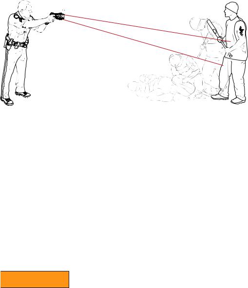
The TASER X3 ECD is a software upgradable, 3-shot ECD manufactured by TASER International, Inc. ECDs use propelled wires or direct contact to conduct energy to affect the sensory and motor functions of the nervous system. The X3 ECD offers a multi-shot capability that previous-generation TASER ECDs do not. The X3 ECD deploys Smart Cartridges one at a time. It is possible to apply energy beyond the initial burst to a deployed cartridge without deploying the remaining cartridges. It also is possible to apply a Warning Arc™ display or drive-stun without deploying any of the cartridges loaded in the ECD.
The X3 ECD uses three replaceable X3 Smart Cartridges containing compressed nitrogen to deploy two small probes that are attached to the X3 ECD by insulated conductive wires. The X3 ECD transmits electrical pulses along the wires and into the body affecting the sensory and motor functions of the peripheral nervous system. The energy can penetrate up to 1.5 cumulative inches of clothing, or 0.75 inches per probe. The cartridges are available with various wire lengths from 15’to 35’(4.6 meters to 10.7 meters). X3 Smart Cartridges are equipped with Charge Diffusion™ probes for optimal Neuro Muscular Incapacitation (NMI) pulse delivery.
The X3 ECD’s Trilogy Log™ can be uploaded securely to EVIDENCE.COM, where the information is encrypted, stored securely, and organized into dashboards that allow your agency to easily monitor the usage and system status of your entire arsenal of X3 ECDs.
The X3 ECD’s optional TACOM™ Digital Power Magazine, or TPM, enables the X3 ECD to communicate wirelessly to other TACOM enabled ECDs such as the AXON Tactical Computer for time synchronization and event triggering. Furthermore, the X3 ECD features a Power Optimization Control (POC) capability that continually monitors the power remaining in the battery pack and, when needed, shuts down peripheral functions to maintain critical NMI capability while warning the user when the battery power reaches low levels.
The X3 ECD has an internal memory that stores the operating software and a record of every deployment. See the "Trilogy Log" section in this manual for more details.
The X3 ECD’s capabilities are encased within a rugged unibody chassis. This rugged structure protects the enclosed circuitry from hostile environments. Additionally, the unibody polymer frame provides much greater structural integrity and impact survivability than previous clamshell housings.
6
Neuro Muscular Incapacitation (NMI)
The human nervous system communicates with simple electrical impulses. The command center (brain and spinal cord) processes information and makes decisions. The peripheral nervous system includes the sensory and motor nerves. The sensory nerves carry information from the body to the brain (temperature, touch, etc.). The motor nerves carry commands from the brain to the muscles to control movement and can be involuntary in response to the sensory information. An example would be the involuntary muscle reaction to pull a hand away from a hot object.
TASER technology uses similar electrical impulses to cause stimulation of the sensory and motor nerves. Neuro Muscular Incapacitation (NMI) occurs when an ECD is able to cause involuntary stimulation of both the sensory nerves and the motor nerves. It is not dependent on pain and is effective on subjects with a high level of pain tolerance.
Previous generations of stun guns primarily affected the sensory nerves only, resulting in pain compliance. A subject with a very high tolerance to pain (e.g., a drug abuser or a trained, focused fighter) might be able to fight through the pain of a traditional stun gun.
Common Effects of NMI

 WARNING
The use of TASER technology causes incapacitation and strong muscle contractions making secondary injuries a possibility. These potential injuries include but are not limited to: cuts, bruises, impact injuries, and abrasions caused by falling, and strain-related injuries from strong muscle contractions such as muscle or tendon tears, or stress fractures. These injuries are secondary in nature and not directly attributable to the electric output of the ECD, but are possible consequences of the strong muscle contractions the ECD induces to produce incapacitation. Some of the effects may include:
•Falls immediately to the ground and inability to catch oneself;
•Risk of drowning if ability to move in water or wet environments is restricted;
7 |
Chapter 2 General Information |
|
|
•Yelling or screaming;
•Involuntary strong muscle contractions;
•Freezing in place with legs locked;
•Dazed feeling for several seconds or minutes;
•Potential vertigo;
•Temporary tingling sensation; or
•Critical stress amnesia (may not remember any pain).
For a full list of warnings, visit www.TASER.com.
Basic X3 Electrical Theory
•Electricity must be able to flow between the probes or the electrodes.
•Electricity generally follows the path of least resistance between the probes.
•The greater the spread between the probes on the target, generally the greater the NMI effectiveness.
•Electricity will generally not pass to others in contact with the subject unless contact is made directly between or on the probes.
•Electricity can arc through clothing, and even some bullet-resistant materials.
•Exposure to water will not cause electrocution or increase the power to the subject (the electrical charge is fixed inside the TASER ECD, and will not increase significantly even with environmental changes).
•The X3 ECD’s Rotational-Pulse Drive™ rotates discharges across the three cartridge bays. This alternation of pulsed output across multiple cartridges allows a single X3 ECD to incapacitate up to three subjects simultaneously with the same effectiveness previously only possible with three separate ECDs.
•The Rotational Pulse Drive supports cross connection, or X-Connect™ technology, which can make the X3 ECD effective even if some probes from multiple cartridges do not hit the target. As long as one top probe and one bottom probe hit the subject, the NMI circuit can be completed, even if the probes were deployed from different cartridges.
•The Precision Shaped Pulse™ Pulse Calibration System (PCS)™ is designed to adjust current to meet situational requirements. If two probes strike a target and one contact is weak, the ECD will adapt to enhance the weaker contact’s effectiveness. If all probes from two or more cartridges strike the same target, the PCS is designed to adjust so the effect on the target is same as that of a solid contact from a single cartridge.
•Medical studies have found that modern pacemakers and implanted cardiac defibrillators withstand external electrical defibrillators many orders of magnitude stronger than the TASER conducted energy pulses.
Chapter 2 General Information |
8 |
|
|
Features & Operation |
3 |
|
|
|
|
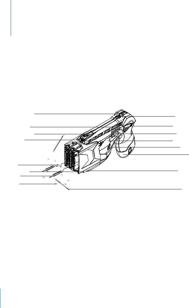
X3 ECD and Cartridge Features
Get to know the X3 ECD:
Mechanical Sight
Mounting Rail
Mechanical Sight
Top Laser
Wire
LED Flashlight
Probe
AFIDs
CAM-Lock Safety
Ambidextrous safety can be operated from either side.
Selector Switch
CAM-Lock Safety
Trigger Switch
Index Finger Rest
ARC Switch
EPM
Bottom Laser
Blast Door
•CAM-Lock Safety down (SAFE).
•CAM-Lock Safety up (ARMED) and ready to deploy.
•Do not block the safety on one side of the X3 ECD while attempting to move it on the other side. This can break the safety and disable the ECD.
•With default settings, if the X3 CAM-Lock Safety is left in the up (ARMED) position for more than 20 minutes, the system will shut down to preserve battery life. (This feature can be turned off, which then will cause the X3 ECD to be left on indefinitely when the safety is up (ARMED). See the "Auto Power Down" section in this manual for more information. To re-arm the ECD, simply shift the safety to the down (SAFE) position, and then shift it back to the up (ARMED) position.
9
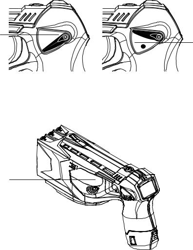
Down (SAFE)
Up (ARMED)
Index Finger Rest
On each side of the X3 ECD is an ergonomically designed rest upon which to place the tip of your index finger when you are not pressing the trigger switch or the ARC switch.
Index Finger Rest
Arc display/Re-energize/Cartridge advance (ARC) Switch
The ARC switch is used to employ a Warning Arc display, select cartridges, and select menu items during system programming and option selection. ARC switch functions are described in the "Arc display/Re-energize/
Cartridge advance (ARC) Switch Functions", "Configuring the X3 ECD" and viewing the System Status sections of this document.
Enhanced Power Magazine (EPM)
The Enhanced Power Magazine is a lithium energy cell power supply system for the X3 ECD.
Do not store the EPM anywhere that the gold contacts on the side of the EPM may touch metal objects. If you cause an electrical short between these contacts, the short will drain the lithium energy cells and may cause the pack itself to become dangerously hot.
The EPM has enough power for approximately 300 discharges depending on temperature and use of the
Chapter 3 Features & Operation |
10 |
|
|
flashlight. The EPM will deplete faster in colder weather than warm weather. Likewise, the EPM will deplete faster with the flashlight active.
1Remove the protective label from the EPM contacts before installing the EPM battery in the X3 ECD.
2Inspect the contacts to ensure the adhesive residue has been removed.
Contacts
For more information on installing the EPM, see the "Changing the EPM" section in this manual.
Enhanced Power Magazine (EPM)
Changing the EPM
1Point the ECD in a safe direction.
2Ensure the CAM-Lock Safety is in the down (SAFE) position.
3Remove the Smart Cartridges. See the "Unloading" section in this manual for more information.
4To unload the EPM power pack:
4a Press and hold the EPM lock button located on the back of the EPM. 4b Press the release buttons located on both sides of the EPM.
4c Pull firmly in a downward motion on the EPM to remove it from the ECD.
Release Button |
Release Button |
EPM Lock Button
4d Wait approximately five seconds.
11 |
Chapter 3 Features & Operation |
|
|

4e Remove the protective label from the new EPM.
4f Install the new EPM. Ensure that the EPM is fully inserted into the X3 ECD. Apply sufficient
force to ensure the EPM is fully seated and the tabs on the sides of the EPM are properly engaged.
Optional Rechargeable TACOM Power Magazine (TPM)
The optional TPM is a rechargeable battery module with integrated TACOM wireless communication capability. The TPM has enough power for approximately 100 discharges depending on temperature. The TPM will use more energy in colder weather than warm weather. Battery life also will vary depending on the flashlight usage.
Central Information Display (CID) Color Graphic User Interface
The display on the back of the X3 ECD provides information about the ECD. When the CAM-Lock safety is shifted into the up (ARMED) position, the CID will display the cartridge bays, diagnostic status, and battery status.
Central Information Display (CID) Color Graphic User Interface
Cartridge Icons
|
|
|
|
|
|
|
Left to right: 35-, 25-, and 15-foot live cartridges. These cartridges have not been deployed. |
|
|
|
|
|
|
|
Note that the cartridge icons are displayed in the same color as those of the blast door |
|
|
|
|
|
|
|
|
|
|
|
|
|
|
|
|
|
|
|
|
|
|
|
colors for the corresponding ranges (orange for 35, green for 25, and yellow for 15). |
|
|
|
|
|
|
|
|
|
|
|
|
|
|
|
If your X3 ECD is set up for metric measurements, the same cartridges will be displayed |
|
|
10m |
|
7m |
|
4m |
like this: 10, 7, and 4 meters in place of 35', 25', and 15', respectively. (Metric numbers are |
|
|
|
|
||||
|
|
|
|
||||
|
|
|
|
|
|
|
rounded down on the CID.) |
Training cartridges will display with a solid blue icon shown in English or metric depending on the X3 ECD’s settings.
The currently selected cartridge will be surrounded by a green border. If you press the trigger switch, this is the cartridge that will be deployed.
If you press the trigger switch, the cartridge energized icon will display while the NMI burst is in progress.
After a cartridge has been expended, the cartridge deployed icon is displayed.
|
|
|
|
|
|
|
12 |
|
|
|
|
|
|
|
|
Chapter 3 Features & Operation |
|
||||||
|
|||||||
|
|
|
|
|
|
|
|
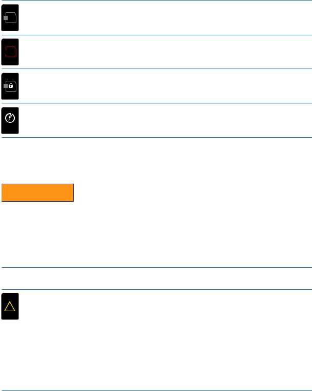
If no cartridge is loaded in the cartridge bay, the cartridge bay empty icon is displayed.
If something is wrong with the cartridge, the cartridge bay error icon is displayed. See  ! the "Load the Smart Cartridges" section in this manual for instructions on loading and
unloading Smart Cartridges from an X3 ECD.
If training cartridges and live cartridges are both loaded into the ECD, the system is designed to lock the live cartridges to keep them from deploying. The cartridge bay locked icon will display in place of those live cartridges.
When you shift the CAM-Lock safety to the down (SAFE) position, a TASER logo and the X3 ECD’s serial number display briefly. This is user changeable.
090701007
Central Information Display (CID) Color Graphic User Interface System Status Icons

 WARNING
The system status icons are designed to inform you of a fault in the X3 ECD. It is a fault indicator only, and it is the user’s responsibility to heed the fault indicators, obtain proper maintenance and repair, and ensure that the ECD is working properly before any use. Failure to heed the system status icons could cause serious injury or death.
All faults are recorded in the X3 ECD’s engineering log.
When the CID shows nothing in the lower-left side, the diagnostic system is indicating that no problems are detected.
Minor Fault indication. A yellow triangle in the CID indicates a minor localized problem. It ! is like a low fuel tank indicator. No Major or Critical Systems have failed yet, but some minor
error has occurred that may need further action.
Shift the CAM-Lock safety to the down (SAFE) position and then to the up (ARMED) position; the fault may clear. If this does not work, remove and reinsert the EPM/TPM. If this does not work, remove and reload the cartridges. If the fault does not clear, it may still be possible to use the ECD for a short time.
If the fault did not clear, correct it as soon as possible. If necessary, send the ECD to TASER International for repair. See the "Product Returns" section in this manual for instructions.
13 |
Chapter 3 Features & Operation |
|
|

!
!
Major Fault indication. A red triangle is probably accompanied by a noticeable failure in the ECD. For example, the flashlight or a laser might not be working. A major fault indicates a subsystem failure. The ECD still may produce an NMI effect, but the ECD is no longer functioning as intended.
Shift the CAM-Lock safety to the down (SAFE) position and then to the up (ARMED) position; the fault may clear. If the fault does not clear, it may still be possible to use the ECD for a short time.
If the fault did not clear, send the ECD to TASER International for repair. See the "Product Returns" section in this manual for instructions.
Critical Fault indication. A stop sign indicates a system failure. The ECD is NOT to be used.
Critical faults are rare. Shift the CAM-Lock safety to the down (SAFE) position and then to the up (ARMED) position; the fault may clear.
If the fault does not clear, do NOT attempt to use the ECD. Send it to TASER International for repair. See the "Product Returns" section in this manual for instructions.
NOTE: If no icons of any kind display on the CID and the CAM-Lock safety is in the up (ARMED) position, but there is a solid red light at the top edge of the CID, then the CID has failed. The X3 ECD may be working—check the ECD to see if the lasers and flashlight are still operating. However, the CID is broken. Send the ECD to TASER International for repair. See the "Product Returns" section in this manual for instructions.
Battery Not Recognized. If you see a question mark within the battery icon of the battery status icon this indicates that the ECD did not recognize the battery correctly. Remove the EPM/TPM and reinsert it. If the error is still present, try another battery. If the Battery Not Recognized icon still displays, this usually indicates that something has happened to the battery connector inside the handle and the handle should be sent in for service. See the "Product Returns" section in this manual for instructions.
Stealth. When the ECD is in the stealth mode, a letter S will display in the battery icon. (See the "Selector Switch" section in this manual for more information about the stealth mode.)
Central Information Display (CID) Color Graphic User Interface Circuit Status Icons
Circuit status icons indicate the degree of connection to the target. Circuit status icons are for reference only; they are not intended to replace the need to look for visual indications or listen for other indications to determine the subject’s connection status.
When the ECD has a good connection to the target, the good circuit completion icon is displayed.
Chapter 3 Features & Operation |
14 |
|
|
The partial/intermittent circuit completion icon indicates that the connection is marginal.
If the connection is not effective, the no circuit completion icon is displayed. The probes may have missed the target.
Central Information Display (CID) Color Graphic User Interface Operating Mode Icons
If the semi-automatic operating mode is selected, this icon is displayed on the CID.
If the manual operating mode is selected, the manual icon displays on the CID.
When the training mode is selected, the training icon displays on the CID.
Central Information Display (CID) Color Graphic User Interface Power Module Power Level (Energy Cell Indicator)
When the CAM-Lock safety is in the up (ARMED) position, the CID will display the percentage of EPM/TPM power remaining. Remaining capacity will display in 10 percent increments. When 30 percent is remaining, the capacity indicator will turn from green to yellow. When the capacity drops to 10 percent, the indicator turns red.
When the battery level drops to 20 percent, TASER International recommends that the battery be replaced (if it is an EPM) or recharged (TPM).
|
|
|
|
|
|
|
|
|
|
|
|
|
|
|
|
|
|
|
|
|
|
|
|
|
|
|
|
|
|
|
|
|
|
|
|
|
|
|
|
|
|
|
|
|
100% |
90% |
80% |
70% |
60% |
||||||||||
|
|
|
|
|
|
|
|
|
|
|
|
|
|
|
|
|
|
|
|
|
|
|
|
|
|
|
|
|
|
|
|
|
|
|
|
|
|
|
|
|
|
|
|
|
|
|
|
|
|
|
|
|
|
|
|
|
|
|
|
|
|
|
|
|
|
|
|
|
|
|
|
|
|
|
|
|
|
|
|
|
|
|
|
|
|
|
|
|
|
50% |
40% |
30% |
20% |
10% |
|
|
|
|
|
15 |
Chapter 3 Features & Operation |
|
|
Central Information Display (CID) Color Graphic User Interface
Spark Duration
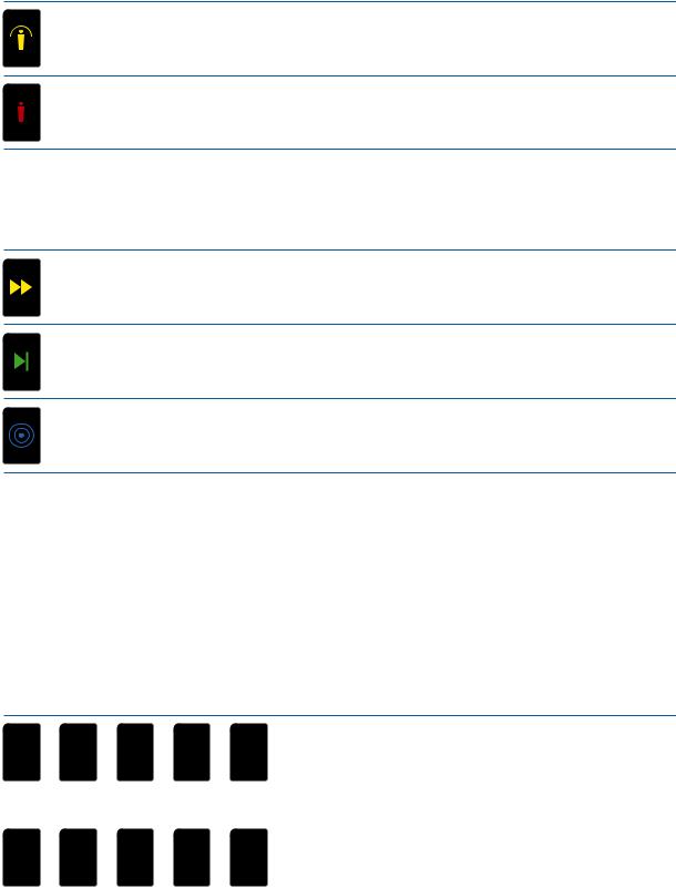
When the X3 ECD is deployed with the trigger switch, it delivers an automatic 5 second Precision Shaped Pulse deployment cycle. The CID displays a count from 1 to 5 indicating how many seconds the deployment cycle has lasted.
1 2
2 3
3 4
4 5
5 
If you hold the trigger switch down continuously, for more than five seconds, the ECD will continue the deployment cycle. The CID will display the number 6 (and sequential numbers), but the icon showing the count will be replaced by the operating mode icon.
6  7
7 
If you press the ARC switch, the CID will display the deployment cycle duration next to the operating mode icon.
1 |
2 |
3 |
4 |
5 |
In probe-deployment mode, the CID display shows the deployment cycle duration for the most recent cartridge deployed. If you then deploy a second Smart Cartridge™ a few seconds later (while the first cycle is running), the CID will stop showing data for the first cartridge (though the first cartridge will still complete its deployment cycle) and start displaying the deployment cycle duration for the second cartridge.
In the example below, the deployment cycle for the second cartridge has been cycling for two seconds. The first cartridge also is cycling, but only the count for the second cartridge is displayed. (If the second cartridge was activated while the first cartridge was still running, the first cartridge's cycle should end before the second cartridge's cycle does. If the first cartridge completed a full cycle before the second cartridge was activated, then both the first and second cartridges should run for the same amount of time.)
Selected Cartridge |
|
|
|
|
|
|
|
|
|
|
|
|
|
|
|
|
Additional Cartridge |
Cartridges Energized |
|
|
|
|
|
|
|
|
|
|
|
|
|
|
Energy Cell Indicator; |
||
Seconds Elapsed in |
|
|
|
|
|
|
|
|
|
|
|
|
|
||||
|
|
|
|
|
|
|
|
|
|
|
|
||||||
2 |
|
|
|
|
|
|
|
|
|
|
|
80% Remaining |
|||||
|
|
|
|
|
|
|
|
|
|
|
|||||||
|
|
|
|
|
|
|
|
|
|
||||||||
Selected Cartridge's |
|
|
|
|
|
|
|
|
|
|
|
Operating Mode (Manual) |
|||||
|
|
|
|
|
|
|
|
|
|
|
|||||||
Burst (2) |
|
|
|
|
|
|
|
|
|
|
|
|
|||||
|
|
|
|
|
|
|
|
|
|
|
|
|
|
||||
|
|
|
|
|
|
|
|
|
|
|
|
|
|
|
|
|
|
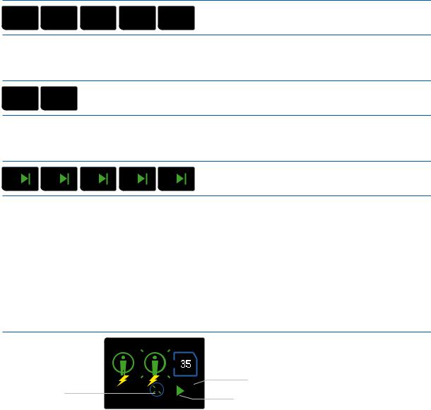
The cycle can be stopped at any time by shifting the CAM-Lock safety to the down (SAFE) position. The CID below shows the X3 ECD loaded with a 25-foot (7 m) and two 35-foot (10 m) cartridges. The 25-foot cartridge is selected. (The leftmost, active cartridge is always selected by default.) The battery is fully charged, and the ECD is in the manual mode. There is a critical fault in the system.
Chapter 3 Features & Operation |
16 |
|
|
Cartridge Color Indicator |
(Blast Door) Color |
Selected Cartridge |
System Status Indicator – |
! |
|
Critical Fault |
|
|
Cartridge Type
Energy Cell Indicator;
Fully Charged
 Operating Mode (Manual)
The CID below shows the X3 ECD set to display metric information. The first cartridge is energized and has been cycling for three seconds; the other two (both are 10 m/35 ft cartridges) have not been selected. The battery is fully charged. There is a minor fault in the system.
Deployment Status |
|
|
|
|
|
|
|
|
|
|
|
|
|
|
|
|
|
|
|
|
|
Metric Cartridges |
|||
Indicator; |
|
|
|
|
|
|
|
|
|
|
|
|
|
|
|
|
|
|
|
|
|
|
|
|
|
|
|
|
|
|
|
|
|
|
|
|
10m |
|
10m |
|
|
||||||||||
Connection Good |
|
|
|
|
|
|
|
|
|
|
|
|
|||||||||||||
|
|
|
|
|
|
|
|
|
|
||||||||||||||||
|
|
|
|
|
|
|
|
|
|
|
|
||||||||||||||
Cartridge Energized |
|
|
|
|
|
|
|
|
|
|
|
|
|
|
|
|
|
|
|
|
|
|
Seconds Elapsed in |
||
|
|
|
|
! |
|
|
|
|
3 |
|
|
|
|
|
|
|
|
|
|
|
|
||||
|
|
|
|
|
|
|
|
|
|
|
|
|
|
|
|
|
|
||||||||
System Status Indicator |
|
|
|
|
|
|
|
|
|
|
|
|
|
|
|
|
|
|
|
|
Burst (3) |
||||
|
|
|
|
|
|
|
|
|
|
|
|
|
|
|
|
|
|||||||||
– Minor Fault |
|
|
|
|
|
|
|
|
|
|
|
|
|
|
|
|
|
|
|
|
|
|
|||
|
|
|
|
|
|
|
|
|
|
|
|
|
|
|
|
|
|
|
|
|
|
|
|
|
|
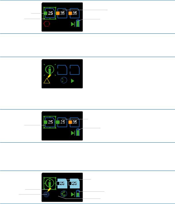
The CID below shows the X3 ECD loaded with two 25-foot cartridges and one 35-foot cartridge. One of the 25foot cartridges is selected, the battery is 80 percent full, and the ECD is in the manual mode.
25-Foot and 35-Foot Cartridges
Selected Cartridge
Energy Cell Indicator;
80% Remaining
 Operating Mode (Manual)
The CID below shows that the X3 ECD is delivering a cycle to the target via probe deployment. The connection is good, and the cycle has been in progress for two seconds. The ECD is in the training mode. (When the ECD discharges, the semi-automatic/manual indicator is not displayed.) The ECD is loaded with training cartridges, and the battery is at 60 percent.
|
|
25-Foot Training Cartridges |
|
|
10m |
10m |
|
Cartridge Energized |
2 |
60% Remaining |
|
Training Mode |
|||
Seconds Elapsed in |
|||
|
Burst (2)
The CID below shows that the X3 ECD is in the training and manual modes, with a 25-foot training cartridge selected, and a 35-foot training cartridge also is loaded. A live cartridge is loaded between the two training cartridges; the center cartridge bay is locked. Sixty percent of the battery life remains.
17 |
Chapter 3 Features & Operation |
|
|

Selected Cartridge |
Cartridge Locked |
|
|
35-Foot Training Cartridge |
|
Training Mode |
60% Remaining |
|
Operating Mode (Manual) |
||
|
The CID below shows an X3 ECD in the semi-automatic mode, with a battery 80 percent full. The first and second cartridges should be ready for use; the first cartridge is selected. The third has a problem, and will not deploy. See"Load the Smart Cartridges" section for instructions on how to unload an X3 ECD.
Selected Cartridge |
|
|
|
|
|
|
|
|
|
|
|
|
|
|
Cartridge Bay Error |
|
|
|
|
|
|
|
|
|
|
|
|
|
|
||||
|
|
|
|
|
|
|
|
|
|
! |
|
|
||||
25-Foot Cartridges |
|
|
|
|
|
|
|
|
|
|
|
|
Energy Cell Indicator; |
|||
|
|
|
|
|
|
|
|
|||||||||
|
|
|
|
|
|
|
|
|
|
|||||||
|
|
|
|
|
|
|
|
|
|
|
|
|
||||
|
|
|
|
|
|
|
|
|
|
|
|
|
|
|
||
|
|
|
|
|
|
|
|
|
|
|
|
|
|
|
|
80% Remaining |
|
|
|
|
|
|
|
|
|
|
|
|
|
|
|
|
|
|
|
|
|
|
|
|
|
|
|
|
|
|
|
|
|
Operating Mode |
|
|
|
|
|
|
|
|
|
|
|
|
|
|
|
||
|
|
|
|
|
|
|
|
|
|
|
|
|
|
|
|
(Semi-Automatic) |
|
|
|
|
|
|
|
|
|
|
|
|
|
|
|
|
|
The CID below shows an X3 ECD in the manual mode, with a battery 80 percent full. The ARC Switch is pressed for a Warning Arc display or drive-stun, energizing all cartridge bays. The center cartridge is selected because pressing the ARC switch, in either the manual or semi-automatic mode, advances the cartridge selection. The third cartridge bay is empty.
Selected Cartridge |
|
|
|
|
|
|
|
|
|
|
|
|
|
|
Empty Cartridge Bay |
All Cartridge Bays Energized |
|
|
|
|
|
|
|
|
|
|
|
|
Energy Cell Indicator; |
||
|
|
|
|
|
|
|
|
|
|
|
|
||||
|
|
|
|
|
|
|
|
|
|
|
|||||
|
2 |
|
|
|
|
|
|
|
|
|
80% Remaining |
||||
Seconds Elapsed in |
|
|
|
|
|
|
|
|
|
|
|||||
|
|
|
|
|
|
|
|
|
|
||||||
Burst (2) |
|
|
|
|
|
|
|
|
|
|
Operating Mode (Manual) |
||||
|
|
|
|
|
|
|
|
|
|
|
|
|
|
|
|
Top Laser
The laser installed in the X3 ECD is oriented to the approximate position of a top probe’s trajectory at 15 feet.
Range Adjusted Dual Laser Sight (RADLS)
This feature is designed to provide bottom dart alignment. The module has two lasers. One of the lasers is active only when a standard-range Smart Cartridge is detected, and it is aligned with the approximate trajectory of the bottom probe of a standard-range (15'/4 m or 25'/7 m) cartridge. The other laser is active only when the long-range (35'/10 m) Smart Cartridge is detected, and is aligned with the approximate trajectory of the bottom probe of a long-range cartridge.
Chapter 3 Features & Operation |
18 |
|
|

Top Laser
Long-Range (35'/10 m) Laser |
Standard-Range (15'/4 m) Laser |
Focused Beam LED Flashlight
Mechanical Sights
The mechanical sights on the X3 ECD are molded to provide manual aiming of the ECD. The mechanical sights are set to coincide with a top probe’s trajectory at a 15-foot distance.
Selector Switch
Front Mechanical Sight |
Rear Mechanical Sight |
Focused Beam LED Flashlight
The X3 ECD has a flashlight that projects most of its light energy as a focused beam, and the remaining light energy as a diffused beam. The Focused Beam LED Flashlight is designed to illuminate a man-sized target within the X3 ECD’s operating range.
19 |
Chapter 3 Features & Operation |
|
|
 Loading...