

Page 1
Digital Audio Production Environment
9101438700
REFERENCE MANUAL
Ü
The lightning flash with arrowhead symbol, within an equilateral triangle, is intended to alert
ÿ
Ÿ
This appliance has a serial number
located on the rear panel. Please record
the model number and serial number
and retain them for your records.
Model number
Serial number
the user to the presence of uninsulated “dangerous voltage” within the product’s enclosure
that may be of sufficient magnitude to constitute a risk of electric shock to persons.
The exclamation point within an equilateral triangle is intended to alert the user to the presence of important operating and maintenance (servicing) instructions in the literature
accompanying the appliance.
CAUTION: TO REDUCE THE RISK OF ELECTRIC SHOCK, DO NOT
REMOVE COVER (OR BACK). NO USER-SERVICEABLE PARTS INSIDE.
REFER SERVICING TO QUALIFIED SERVICE PERSONNEL.
WARNING: TO PREVENT FIRE OR SHOCK
HAZARD, DO NOT EXPOSE THIS
APPLIANCE TO RAIN OR MOISTURE.
Page 2

TASCA M Software License Agreement
THIS SOFTWARE LICENSE AGREEMENT
(“LICENSE”) IS AN AGREEMENT BETWEEN
YOU AND TASCAM, ADIVISION OF TEAC
AMERICA INC. (“TASCAM”). TASCAM IS
WILLING TO LICENSE THE ENCLOSED SOFTWARE TO YOU ONLY UPON THE CONDITION
THAT YOU ACCEPT ALL OF THE TERMS CONTAINED IN THIS LICENSE. PLEASE READ THIS
LICENSE CAREFULLY BEFORE USING THE
SOFTWARE. BY USING THE SOFTWARE YOU
INDICATE THAT YOU AGREE TO BE BOUND
BY THE TERMS OF THIS LICENSE. IF YOU DO
NOT AGREE TO THE TERMS OF THIS
LICENSE, TASCAM IS UNWILLING TO
LICENSE THE SOFTWARE TO YOU, AND YOU
SHOULD PROMPTLY RETURN THE UNUSED
SOFTWARE TO THE PLACE WHERE YOU
OBTAINED IT FOR A REFUND.
1. Grant of License. The application, system and all
other software accompanying this License, whether
on CD-ROM or any other media (the “Software”),
and the related documentation, are licensed to you by
TASCAM solely for your own internal purposes, and
only as described in the documentation, on a single
compatible microcomputer. If the Software is to be
used on two or more microcomputers, a separate
license must be obtained. Use on a network is not
permitted. If this Software is an upgrade to a prior
version, then you must be licensed to use the prior
version of the Software in order to exercise the
license rights granted hereunder, and you may only
use the prior version or the upgrade but not both.
2. Restrictions. The Software contains copyrighted
material, trade secrets, and other proprietary material
of TASCAM and its licensors. You agree that in
order to protect those proprietary materials, you will
not decompile, reverse engineer, disassemble or otherwise reduce all or any part of the Software to
human-readable form. You may not modify, rent,
lease, loan, sub-license, distribute or create derivative works based upon the Software in whole or in
part. You may not copy the Software except to make
one additional copy of the Software in the form in
which it is provided to you, only for backup purposes
and provided you reproduce on such copy the TASCAM copyright notices and any other proprietary
legends that are on the original copy of the Software.
You may copy the documentation solely for your personal use. You may transfer the Software and related
documentation, and all your license rights thereto, to
another party by transferring to that party both the
original media on which the Software and related
documentation were provided and a copy of this
License, and provided that the other party reads and
agrees to accept the terms and conditions of this
License. Immediately upon transfer, you have no further rights to use or own copies of the Software or
related documentation and must destroy all copies in
your possession or control. any transfer of the Software must include all prior versions of the Software.
3. Ownership. The Software and documentation are
licensed, not sold, to you for use only under the terms
of this License, and TASCAM reserves all rights not
expressly granted to you in this License. You own the
media on which the Software and documentation are
recorded but TASCAM and/or TASCAM's licensors
retain title to and ownership of the Software and
related documentation, and all intellectual property
rights therein, including, without limitation, copyright, patent rights and trade secrets.
4. Termination. This License is effective until terminated. You may terminate this License at any time by
destroying all copies of the Software and related documentation in your possession or control. This
License will terminate immediately without notice
from TASCAM if you fail to comply with any provision of this License. Upon termination you must
destroy all copies of the Software and related documentation in your possession or control.
5. Export Law Assurances. You agree and certify
that neither the Software nor any other technical data
received from TASCAM will be exported outside the
United States except as authorized and as permitted
by the laws and regulations of the United States. If
the Software has been rightfully obtained by you outside of the United States, you agree that you will not
re-export the Software nor any other technical data
received from TASCAM except as permitted by the
laws and regulations of the United States and the
laws and regulations of the jurisdiction in which you
obtained the Software.
6. Government End Users. If you are acquiring the
Software on behalf of any unit or agency of the
United States Government, the following provisions
apply. The Software constitutes a “commercial item”,
as that term is defined at 48 C.F.R. 2.101, consisting
of “commercial computer software” and “commercial computer software documentation”, as such
2 TASCAM SX-1 Reference Manual
Page 3

terms are used in 48 C.F.R. 12.212, and is provided
to the U.S. Government only as a commercial end
item. Consistent with 48 C.F.R. 12.212 and 48 C.F.R.
227.7202-1 through 227.7202-4, all U.S. Government End Users acquire the Software with only those
rights set forth herein.
7. Limited Warranty on Media. TASCAM warrants
the media on which the Software is recorded to be
free from defects in materials and workmanship
under normal use for a period of ninety (90) days
from the date of purchase as evidenced by a copy of
the receipt. TASCAM's entire liability and your
exclusive remedy will be replacement of the media
not meeting TASCAM's limited warranty returned to
TASCAM with a copy of the receipt. TASCAM will
have no responsibility to replace any media damaged
by accident, abuse or misapplication. ANY
IMPLIED WARRANTIES ON THE MEDIA,
INCLUDING THE IMPLIED WARRANTIES OF
MERCHANTABILITY AND FITNESS FOR A
PARTICULAR PURPOSE, ARE LIMITED IN
DURATION TO NINETY (90) DAYS FROM THE
DATE OF DELIVERY. THIS WARRANTY GIVES
YOU SPECIFIC LEGAL RIGHTS, AND YOU
MAY ALSO HAVE OTHER RIGHTS WHICH
VARY BY JURISDICTION.
8. Disclaimer of Warranty. THE SOFTWARE
AND RELATED DOCUMENTATION ARE PROVIDED “AS IS” AND WITHOUT WARRANTY
OF ANY KIND. YOU EXPRESSLY ACKNOWLEDGE AND AGREE THAT USE OF THE SOFTWARE AND RELATED DOCUMENTATION IS AT
YOUR SOLE RISK. SHOULD THE SOFTWARE
OR RELATED DOCUMENTATION PROVE
DEFECTIVE, YOU (AND NOT TASCAM OR
ANY TASCAM'S REPRESENTATIVE) ASSUME
THE ENTIRE COST OF ALL NECESSARY SERVICING, REPAIR OR CORRECTION. TASCAM
OR ANY TASCAM'S LICENSORS EXPRESSLY
DISCLAIM ALL OTHER WARRANTIES WITH
RESPECT TO THE SOFTWARE AND RELATED
DOCUMENTATION, WHETHER SUCH WARRANTIES ARE EXPRESS OR IMPLIED,
INCLUDING, BUT NOT LIMITED TO, THE
IMPLIED WARRANTIES OF MERCHANTABILITY, FITNESS FOR A PARTICULAR PURPOSE
AND NON-INFRINGEMENT. WITHOUT LIMIT-
ING THE GENERALITY OF THE FOREGOING,
TASCAM AND TASCAM'S LICENSORS MAKE
NO WARRANTY OR REPRESENTATION THAT
THE FUNCTIONS CONTAINED IN THE SOFTWARE WILL MEET YOUR REQUIREMENTS,
THAT THE OPERATION OF THE SOFTWARE
WILL BE UNINTERRUPTED OR ERROR-FREE,
THAT DEFECTS IN THE SOFTWARE WILL BE
CORRECTED, OR THAT THE SOFTWARE AND
RELATED DOCUMENTATION WILL BE CORRECT, ACCURATE, OR RELIABLE. NO ORAL
OR WRITTEN INFORMATION OR ADVICE
GIVEN BY TASCAM OR ANY OF ITS EMPLOYEES, REPRESENTATIVES, OR RESELLERS
SHALL CREATE ANY WARRANTY IN ADDITION TO THOSE GIVEN HEREIN. SOME JURISDICTIONS DO NOT ALLOW THE EXCLUSION
OF IMPLIED WARRANTIES, SO THE ABOVE
EXCLUSION MAY NOT APPLY TO YOU.
9. Limitation of Liability. UNDER NO CIRCUMSTANCES SHALL TASCAM BE LIABLE FOR
ANY INCIDENTAL, SPECIAL OR CONSEQUENTIAL DAMAGES THAT RESULT FROM THE
USE OR INABILITY TO USE THE SOFTWARE
OR RELATED DOCUMENTATION UNDER ANY
THEORY, INCLUDING CONTRACT, TORT, OR
NEGLIGENCE, EVEN IF TASCAM HAS BEEN
ADVISED OF THE POSSIBILITY OF SUCH
DAMAGES. SOME JURISDICTIONS DO NOT
ALLOW THE LIMITATION OR EXCLUSION OF
LIABILITY FOR INCIDENTAL OR CONSEQUENTIAL DAMAGES SO THE ABOVE LIMITATION OR EXCLUSION MAY NOT APPLY TO
YOU.
IN NO EVENT SHALL TASCAM'S LIABILITY
TO YOU FOR DAMAGES, LOSSES, AND
CAUSES OF ACTION (WHETHER IN CONTRACT, TORT (INCLUDING NEGLIGENCE) OR
OTHERWISE), IF ANY, EXCEED THE AMOUNT
PAID BY YOU FOR THE SPECIFIC LICENSE OF
THE SOFTWARE AND RELATED DOCUMENTATION TO WHICH THE LIABILITY IS
RELATED.
YOU ARE URGED TO FREQUENTLY BACK-UP
YOUR DATA AND YOU ASSUME FULL
RESPONSIBILITY FOR FAILURE TO DO SO.
TASCAM SX-1 Reference Manual 3
Page 4

10. Controlling Law and Severability. THIS
LICENSE SHALL BE GOVERNED BY AND
CONSTRUED IN ACCORDANCE WITH THE
LAWS OF THE UNITED STATES AND THE
STATE OF CALIFORNIA, EXCEPT FOR ITS
CONFLICT OF LAWS PRINCIPLES. If for any reason a court of competent jurisdiction finds any provision of this License, or portion thereof, to be
unenforceable, that provision of the License shall be
enforced to the maximum extent permissible so as to
effect the intent of the parties, and the remainder of
this License shall continue in full force and effect.
11. Complete Agreement. This License constitutes
the entire agreement between the parties with respect
to the use of the Software and related documentation
and supersedes all prior or contemporaneous understandings or agreements, written or oral, regarding
such subject matter. No amendment to or modification of this License will be binding unless in writing
and signed by an authorized officer of TASCAM.
4 TASCAM SX-1 Reference Manual
Page 5

Part I — Manuals & Conventions
Table of Contents
Chapter 1 – The Manuals
Manual Descriptions .................................. 10
Owner's Manual .............................................10
Quick Start Guide............................................10
Manual Organization ................................. 10
Documentation Conventions..................... 11
Tips...................................................................11
Chapter 2 – Operating Conventions
Front Panel.................................................. 12
Multi-Function Keys........................................12
Data Entry .......................................................12
Keypad.............................................................12
Ancillary Keys ............................................. 13
Jog/Shuttle Wheel ..........................................13
Virtual Channel Pots.......................................13
Fader Banks.....................................................14
LCD Display ................................................. 14
VGA or LCD......................................................14
LCD Navigation ...............................................14
Common Soft Knobs & Keys..........................15
Soft Keys......................................................... 15
Soft Knobs ......................................................15
VGA Display................................................. 15
Screen Navigation .......................................... 15
Tracks Display................................................. 16
Mouse Conventions ....................................... 16
Tabs ................................................................. 17
Main Menu Items ...........................................17
Zoom & Scroll.................................................. 17
Main Menu Bar Elements............................... 17
Transport & Record Keys ............................... 17
MIDI Panic ....................................................... 17
Tool Select....................................................... 17
Grid Select....................................................... 18
Nudge & Grid Settings ................................... 18
Edit Length Grids............................................ 18
Time Signature Selector................................. 18
Tempo & Click Management ......................... 18
Project & Mix Menus......................................19
Main Time Code Display ................................ 19
Common buttons ........................................20
Part II — Monitoring Signals and Selecting Screens
Chapter 3 – Monitoring Audio
Output Control ........................................... 21
Monitor Section ..............................................21
CONTROL ROOM.............................................21
STUDIO Section...............................................22
TALKBACK Select ............................................22
Monitor Level..................................................23
SOLO Section...................................................23
HEADPHONES..................................................23
TRANSPORT SOLO...........................................24
Part III — Locate, Transport, & Surround
Chapter 6 – Transport, Loop, Auto Punch
Transport Controls ..................................... 31
Front Panel ......................................................31
JUMP KEY MODE ........................................31
VGA Transport ................................................32
LCD Transport .................................................32
ADD .............................................................33
EDIT ..............................................................33
P2 Remote Machine Control in the SX-1... 34
The Philosophy................................................34
General SX-1 Transport Controls...................34
Customizing the Devices................................34
Chapter 4 – Metering & Indicators
Reading LED Meters....................................25
Master Meter Section..................................... 25
Chapter 5 – Selecting Screens
Screen Controls ...........................................27
Main Display Key............................................ 27
Main Display Mode Section........................... 27
View Menu...................................................... 28
LCD ACCESS Section....................................... 29
LCD Screen ...................................................... 29
Working with External Timecode Sources ...35
LOOP Section .................................................. 37
Auto Record Controls (AUTOPUNCH Section)37
Chapter 7 – Locate Points
Creating Locate Points................................ 38
Create a Locate Point ..................................... 38
Recalling & Editing Locate Points.................. 38
VGA Locate Control .................................... 39
LCD Locate Control .....................................40
LOCATE POINTS .............................................. 40
REGISTERS....................................................... 40
TASCAM SX-1 Reference Manual 5
Page 6

Table of Contents
Chapter 8 – Surround
Setting Up Surround...................................41
Making the Change to Surround................... 41
LCD Access to Surround .................................41
Part IV — Mixer Controls
Chapter 9 – Channel Control
Front Panel...................................................45
Channel Strips.................................................45
Master Channel ..........................................45
Virtual Channel............................................... 46
Screen Control (VGA Channel Display) .........47
CONTROL .....................................................47
POSITION .....................................................48
GROUPS .......................................................48
AUX SEND ...................................................48
EQ ................................................................49
DYNAMICS ..................................................49
Compressor & Expander ............................50
Gate .............................................................50
LCD Channel Display ......................................51
DYN .............................................................51
Aux ON/OFF ................................................ 51
AUX Pre/Post ..............................................51
Links ............................................................51
Buss Routing ............................................... 52
INPUT button ..............................................52
INSERT button .............................................52
TRIM/CH DELAY Screen ..............................52
EQ, Dynamics and Scene Libraries - The Library
Feature ......................................................53
VGA Displays...................................................53
LCD Displays....................................................53
DYNAMICS LIBRARY ...................................53
Scene library................................................54
VGA Scene Tab................................................54
LCD SCENE LIBRARY Screen ...........................55
IMPORT ........................................................55
Chapter 10 – Library Overview
Understanding the Library Feature ...........56
Library Section................................................ 56
Chapter 11 – Routing & Bussing
Working With the SX-1’s Routing Pages ...57
The philosophy ...............................................57
VGA Routing Displays ....................................57
Panel Routing .............................................57
Mixer Routing .............................................58
Before we continue, a word about mixer Bypass
and Loopback ..............................................58
HDR Routing ...............................................58
Effects Routing ...........................................58
Insert Presets ..............................................59
Surround Modes Explained........................... 41
Understanding the Changes ...................... 42
VGA Channel .................................................. 42
Routing Surround Busses........................... 44
LCD Routing Displays..................................... 59
Inserts – how they work and how to route
them............................................................. 59
VGA ................................................................. 60
Actually routing the insert to a mixer
channel ........................................................ 61
LCD .................................................................. 62
Actually routing the insert to a mixer
channel ........................................................ 62
ANALOG IN ..................................................... 63
Bussing ........................................................ 63
VGA Controls.................................................. 63
Buss Masters ............................................... 64
LCD Buss: Controls ......................................... 64
MACRO ....................................................... 65
Buss Assign ................................................. 65
Aux Sends & Returns.................................. 65
VGA Aux Send Controls................................. 65
Aux Send Masters .......................................... 66
LCD Aux Send Controls.................................. 66
VGA Aux Return Masters............................... 67
Routing Library Displays ............................ 68
VGA Routing Library Display......................... 68
LCD Routing Library Display.......................... 68
Chapter 12 – Fader Links, Groups, & Banks
Links............................................................. 69
VGA Fader Links ............................................. 69
LCD Fader Links .............................................. 69
MACRO ....................................................... 70
LINKS ........................................................... 70
Groups ......................................................... 71
VGA Fader Groups.......................................... 71
LCD Fader Groups........................................... 71
Understanding Group Masters...................... 72
Fader Banks................................................. 73
Fader Bank Section......................................... 73
VGA Fader Banks............................................ 74
USER Fader Banks........................................... 75
Creating a User Fader bank (VGA) ................ 75
User Fader Banks (LCD).................................. 76
VGA Bank Menu ......................................... 76
Channel Overview Screens ........................ 77
VGA Buss Overview Screen........................... 77
LCD Buss Overview Screen............................ 78
LCD Mixer Overview Screen.......................... 78
VGA Input Overview Screen.......................... 79
6 TASCAM SX-1 Reference Manual
Page 7

Table of Contents
Chapter 13 – Automation
Understanding Modes & States................. 80
Controller States......................................... 80
Automatic (Auto)............................................80
Static................................................................80
Write................................................................80
Trim..................................................................81
Safe..................................................................81
Off....................................................................81
Global Modes.............................................. 81
Global Write....................................................81
Trim..................................................................81
Init Edit ............................................................82
Rehearse Functionality...................................83
Global Controls........................................... 84
Mix Displays................................................ 84
VGA Mix Tab ...................................................84
LCD MIX Screen...............................................85
Automation Controls ................................. 86
Front Panel Controls.......................................86
VGA Automation Screen............................ 88
Automation Track Area..................................89
Auto Track.......................................................89
Edit Operations (Region/Event select) ..........90
When nothing is selected ..........................90
A region is selected ....................................90
Events selected ........................................... 90
Edit Operations (Pencil Tool)......................... 90
Edit Operations (Curve Tool)......................... 90
LCD CHANNEL screen..................................91
Automation Events & History Screens ......91
Event List Tab .................................................91
Edit Operation ............................................ 91
History Tab...................................................... 92
VGA Automation Global Tab .....................92
Dynamic Automation ................................. 92
LCD GLOBAL Screen....................................94
Operations Examples..................................95
Writing Mix Moves......................................... 95
Revert Time..................................................... 95
Writing Switch Events.................................... 100
Revert Time..................................................... 100
Disabling Control Sense Timeout.................. 102
Trimming Mix Moves ..................................... 102
Revert Time..................................................... 103
Automating Library Recall..........................104
Writing Library Recall Events Over Existing Static
Control Positions......................................... 104
Combining Library Recall With Dynamic Mix
Moves........................................................... 105
Automating Groups.................................... 105
Part V — Effects
Chapter 14 – Working with Effects
The Philosophy – how it works................. 106
VGA Effects Screens ................................... 106
Routing Effects Screens ............................. 107
VGA EFFECTS SLOT/ROUTING Module ..........107
Effect Slot ....................................................107
LCD Effects Routing Screen............................107
EFFECTS .......................................................107
Effects Controls Displays ........................... 108
VGA EFFECTS CONTROLS Screen ...................108
LCD EFFECTS Control Screen ..........................108
Effects Library Displays.............................. 109
VGA EFFECTS LIBRARY Screen .......................109
LCD FX LIBRARY Screens ................................110
Routing Effect Examples............................ 111
Aux Send & Return .........................................111
Inserting an Effect ..........................................111
Part VI — Audio tracks
Chapter 15 – Examples of Effect Algorithms
Categories.................................................... 112
Common Effect Parameters........................ 112
Examples...................................................... 113
Antares Mic Modeler...................................... 113
Signal Flow ................................................. 113
Input Section ..............................................113
Source Mic Section ..................................... 114
Modeled Mic Section .................................115
Preserve Source .......................................... 116
Tube Saturation .......................................... 116
Antares Speaker Modeler...........................117
Tascam DeEssor...........................................117
Tascam Exciter (Stereo) ..............................118
Tascam/Nemesys HD1 Dither.....................118
Type ............................................................. 118
TC SX-1 Reverb............................................ 119
Level Mix Controls .....................................119
Time Editor .................................................120
Chapter 16 – Working with Audio Regions
Essential Tools ............................................ 122
Tool Select Menu ............................................122
VGA Waveform Tab........................................122
Edit Operation.................................................123
Event Editor ................................................123
HyperSelect ................................................. 123
Move ........................................................... 123
Render ......................................................... 123
Repeat Selection ......................................... 123
Reverse ........................................................ 123
Gain/Fade .................................................... 123
Normalize .................................................... 123
TASCAM SX-1 Reference Manual 7
Page 8

Table of Contents
Remove DC ..................................................123
LCD WAVEFORM Screen................................. 124
SELECT .........................................................124
Managing Audio Takes...............................124
VGA Take Browser Tab ..................................125
Audio Clips...................................................125
VGA Clip Browser Tab.................................... 125
Part VII — MIDI Sequencing
Chapter 18 – Essential Controls
MIDI Sequencer ...........................................133
MIDI REC MODE Section.................................133
VGA Tracks Display of MIDI........................133
MIDI Tracks......................................................133
LCD Tracks Display of MIDI.........................134
VGA MIDI Channel Display .........................135
LCD MIDI Channel Display ..........................136
Global Controls............................................136
VGA Global Tab ..............................................136
MIDI Input Settings ........................................138
LCD MIDI Settings Screen...............................139
VGA MIDI Track Tab .......................................139
Transpose........................................................ 144
Transpose Mode ......................................... 144
Track Offset.....................................................145
RELATED LCD screens..................................... 145
Step Record Mode.......................................146
Step Parameters..............................................146
Step Recording................................................147
TIME/TEMPO Management ........................148
VGA Control.................................................148
Accent ..........................................................148
Non Accent ..................................................148
LCD TIME/TEMPO Screens..............................149
Managing MIDI Takes .................................150
VGA Take Browser Tab ..................................150
Managing MIDI Files ...................................150
Standard MIDI Files ........................................151
VGA SMF Management Tab........................... 151
VGA Main Menu SMF Commands .................151
MIDI Monitoring..........................................152
MIDI Overview Screen....................................152
LCD MIDI In Overview Screen........................153
LCD MIDI Out Overview Screen..................... 153
MIDI Naming Tab............................................154
Chapter 19 – MIDI Editing
Tools & Screens ...........................................155
Chapter 17 – Editing Audio
Edit Controls................................................ 127
EDIT ................................................................. 127
NUDGE SETTING ......................................... 127
Editing............................................................. 128
VGA Edit Menu ........................................... 131
Auditioning Edits........................................ 132
AUDITION Section .......................................... 132
A recap — onscreen tools for working with MIDI
events .......................................................... 155
Using the Tools............................................... 155
MIDI Piano Roll Screens.............................. 159
VGA Piano Roll ............................................... 159
Edit Operation................................................ 159
Add Note .................................................... 159
Add Program Change ................................ 159
Adjust Duration .......................................... 159
Adjust Velocity ........................................... 159
Crescendo ................................................... 160
Event Editor.................................................... 160
HyperSelect..................................................... 160
Move ............................................................... 160
Quantize ......................................................... 161
Randomize Duration...................................... 161
Randomize Time............................................. 161
Randomize Velocity ....................................... 161
Repeat Selection............................................. 161
Reverse............................................................ 161
Set Duration ................................................... 161
Set Min/Max Duration................................... 161
Set Min/Max Velocity .................................... 162
Set Velocity..................................................... 162
Smooth Events ............................................... 162
Split Notes ...................................................... 162
Step Record..................................................... 162
Transpose........................................................ 162
Trim Duration ................................................. 162
Trim Velocity................................................... 162
LCD Piano Roll............................................. 163
Event Lists ................................................... 163
VGA Event List................................................ 163
Edit Operations .............................................. 164
Add Lyric ..................................................... 164
Add Time Signature ................................... 164
Tempo Change ........................................... 164
LCD Event List................................................. 165
FILTER .......................................................... 165
JUMP ........................................................... 165
OPTION ....................................................... 165
Part VIII — Data Entry, System & File Management
Chapter 20 – Project Management
Important Screens .......................................166
New Project Screens....................................166
VGA New Project Tab..................................... 166
LCD New Project Screen................................. 167
Manage Project screens.............................. 167
VGA Manage Project Tab............................... 167
8 TASCAM SX-1 Reference Manual
Page 9

Table of Contents
“Safe” startup .................................................168
LCD Manage Screen........................................168
FUNCTIONS ..................................................168
LCD Open Screen ............................................169
Main Menu Bar Project Commands...............169
Chapter 21 – Mixdown, Author, Backup
The SX-1 and Mixdown Mode................... 170
Philosophy – how it works.............................170
Stereo Mixdown – printing your final mix or
comping tracks.............................................170
On the VGA .....................................................170
On the LCD ......................................................171
In Surround Mode – what changes? .............172
On the VGA .....................................................172
On the LCD ......................................................172
Working With the CD Burner .................... 173
ISO Data CD ................................................ 173
Red Book Audio CD .................................... 174
The SX-1 and Hard Drives .......................... 175
Care and feeding, and audio file behavior...175
The Philosophy – drives in general................175
Drives and the SX-1 ........................................176
What is actually put on the drive..................176
What is happening when the SX-1 is
recording......................................................177
The way the SX-1 handles data.....................177
Explanation of Disk Cleanup and Low Level
Format ..........................................................178
How the Backup file is made .........................178
Quick general behavior.................................. 178
Backing Up................................................... 179
Backup Displays.............................................. 179
VGA Project Backup Tab ................................179
LCD Backup Screen......................................... 180
Drive Settings..............................................180
VGA Drive Setup Tab ..................................... 180
LCD Drives Screen........................................... 181
Chapter 22 – System Settings
Preferences.................................................. 182
Preferences Screens ....................................182
VGA UI Settings Tab....................................... 182
LCD Meter Screen........................................... 183
LCD Miscellaneous Screen ............................. 183
LCD Time Screen............................................. 184
About your SX-1............................................. 184
The SX-1 Menu ...............................................185
System Settings...........................................185
System Settings Screens ................................ 185
VGA Global Tab System Settings .................. 185
LCD Hard Drive (HDR) Screen ........................ 186
VGA Clock Settings Tab .................................187
LCD Clock Settings Screen .............................188
LCD EXTERNAL DEVICES Settings Screen...... 189
Digital I/O Settings ..................................... 190
LCD Digital I/O Screens .................................. 190
Option Card Settings ..................................191
Front Panel SHUTDOWN Key ..................... 191
Part IX — Connections and Ports
Chapter 23 – Inputs and Outputs
Top Panel .................................................... 192
OUTPUTS .........................................................192
Part X — Specifications, etc.
Appendix A – PS/2 Keyboard & Mouse
Shortcuts
In General.................................................... 195
Track Management .................................... 195
Piano Roll Management............................. 195
TrackScale View (the grey zooming bar).. 195
Ruler ............................................................ 196
Transport..................................................... 196
Appendix B – Control Surface Shortcuts
SHIFT Key .................................................... 197
CANCEL Key ................................................ 197
Transport Key Combinations..................... 197
Channel Select Key Special Functionality . 198
DIM, MONO & TALKBACK Special
Functionality ............................................ 198
INPUTS............................................................. 192
Rear Panel.................................................... 193
Appendix C – Block Diagrams (i)
Block Diagram (ii)........................................200
Appendix D – Level diagram
Appendix E – Specifications
Physical specifications ................................ 202
Dimensional drawing..................................... 202
Audio specifications....................................203
I/O (analog)..................................................... 203
I/O (digital)...................................................... 204
Synchronization, etc. I/O ............................... 204
Other connections, etc...................................204
Performance ................................................205
Appendix F – MIDI Implementation Chart
TASCAM SX-1 Reference Manual 9
Page 10

Part I–Manuals & Conventions
Chapter 1 – The Manuals
Manual Descriptions
There are two different manuals shipped with the
SX-1: a Quick Start Guide and an Owner's Manual
(this manual). If you are missing either of these man-
Owner's Manual
The Owner's Manual covers all of the SX-1's many
features, controls, and parameters in detail. Its explanations assume that you have a certain knowledgebase about recording and MIDI. If you find yourself
confused by the subjects and terms presented in this
Quick Start Guide
This guide covers all the basics on setting up your
SX-1: unpacking, connecting speakers, listening to
the demo, setting recording levels, and connecting
MIDI. If you are not familiar with setting up record-
Manual Organization
The Owner's Manual is divided into sections called
Parts, and each Part is divided into chapters. The
Parts are designated by Roman numerals (I, II, III,
IV, etc.) while the chapters are designated by Arabic
numerals (1, 2, 3, 4, etc.). Each chapter contains relevant figures of the SX-1’s front panel, and screen
shots of the LCD and VGA displays.
Each Part covers a specific portion of the SX-1 (for
example, the Mixer or the MIDI Sequencer). The
chapters address individual features (such as mixer
automation or editing MIDI data). As such, learning
about a specific section of the SX-1’s functionality is
as simple as reading the appropriate Part.
There are ten Parts.. The following is a brief description of what you can expect to find in each Part.
I, “Manuals & Conventions” (page 10)
This introductory Part explains the organization and
documentation conventions of the Owner's Manual.
It also covers the SX-1's general operating conventions for all three control interfaces: the front panel,
onboard LCD screen, and a connected VGA display.
II, “Monitoring Signals and Selecting
Screens” (page 21)
monitor signals on the SX-1. The front panel meters
and LED indicators are one way, and many of the
There are lots of ways to
uals, you should contact the authorized TASCAM
dealer where you purchased your SX-1. The contents
and purpose of each manual are described below.
manual, you should refer to an introductory handbook on engineering. This manual does not explain
how to set up and begin using the SX-1; for that you
should refer to the Quick Start Guide.
ing equipment (and even if you are) beginning with
the Quick Start Guide is a good idea. For more
detailed explanations on individual features and
functions, refer to the Owner's Manual.
display screens also provide comprehensive metering. This Part covers the SX-1’s many meters and
indicators and explains how to recall the different
display screens.
III, “Locate, Transport, & Surround” (page
31) Understanding how to navigate through your
project quickly and efficiently is key to getting the
most out of your SX-1. This Part explains the SX-1’s
transport and locate controls as well as its recording
conventions.
IV, “Mixer Controls” (page 45) The SX-1 has
a full-featured mixer with a host of powerful features. Routing for the mixer is available pre- and
post- the mixer channels, the channels themselves
have built-in EQ and dynamics, the buss and return
architecture is extremely flexible, and practically
every parameter can be automated and archived. This
section explains the mixer’s structure and operations.
V, “Effects” (page 106) Each onboard effect has
is own unique set of parameters. This Part explains
these parameters for all the currently available effect
algorithms.
VI, “Audio tracks” (page 122) Everything
you need to know about working with and editing
audio regions can be found in this Part. This includes
10 TASCAM SX-1 Reference Manual
Page 11

Part I–Manuals & Conventions
an explanation of different editing features, how to
use the audio editing tools, and selecting and displaying waveforms.
VII, “MIDI Sequencing” (page 133) The SX-
1’s onboard MIDI sequencer is as comprehensive as
a dedicated software-based MIDI sequencer (like the
type you might install on a desktop computer). This
Part covers all of the MIDI sequencer’s features and
addresses working with and editing MIDI note and
continuous controller data.
VIII, “Data Entry, System & File
Management” (page 166) Different applica-
tions require different system setups: sample rates,
bit depths, synchronization, storage, and the like.
Documentation Conventions
The names for all of the SX-1's keys, knobs, and connections are printed in this manual exactly as their
labels appear on the SX-1 itself. They are set apart
from normal text with brackets. For example, the
Play button is written
has more than one function (for example, a main and
shift function—the Shift function is explained in
“Multi-Function Keys” on page 12), it is written as,
ENABLED/ ALL INPUT (the main function is listed
first and the shift function second).
The SX-1's face is organized into different areas for
each of its various functions. These areas are labeled
and their names also appear in this manual exactly as
they are printed on the SX-1 (for example,
EDITING).
Areas of the SX-1 that are not labeled, but have a
specific purpose, are written in conventional title
form (such as, Faders).
PLAY. In the case where a key
This Part covers the SX-1’s system parameters as
well as backing up and project management.
IX, “Connections and Ports” (page 192)
There are a variety of jacks and connectors located
on the top and back of the SX-1. There are also several expansion ports on the unit's rear. This part of
the manual explains the purpose behind each of these
connections.
X, “Specifications, etc.” (page 195) All the
specifications you need to know about the SX-1 are
found in this Part: reference diagrams, keyboard
commands and shortcuts, and technical specs.
In order to differentiate LED labels from area and
control labels, LED names are in angle brackets (for
example,
and menu names that appear on the LCD or the external VGA displays from their hardware counterparts,
these names are in a lighter typeface (like, the
key or the
All the manuals and guides for the SX-1 adhere to
these documentation conventions. Diagrams and
illustrations are presented whenever possible to augment the manual's text descriptions.
Windows is a trademark of Microsoft Corporation.
Mac and Macintosh are trademarks of Apple Computers.
Be is the trademark of Be Incorporated.
All other trademarks mentioned here are the property
of their respective owners.
<DISK>). To distinguish software buttons
LOAD
EQ LIBRARY screen).
Tips
Important notes, that are in addition to general
instructions and definitions, are set apart from the
manual’s normal text titled TIP (see the example
here). These important tips call your attention to special situations and offer helpful operating
suggestions.
TIP
While reading the SX-1 Owner’s Manual, keep your eyes
peeled for special operating tips and helpful suggestions like this.
TASCAM SX-1 Reference Manual 11
Page 12
Part I–Manuals & Conventions
Chapter 2 – Operating Conventions
Front Panel
Multi-Function Keys
Some keys have multiple functions. A key’s primary
function is accessed by simply pressing the key. Secondary functions are accessed by entering Shift
mode. Press the
SHIFT key on the Numeric Keypad,
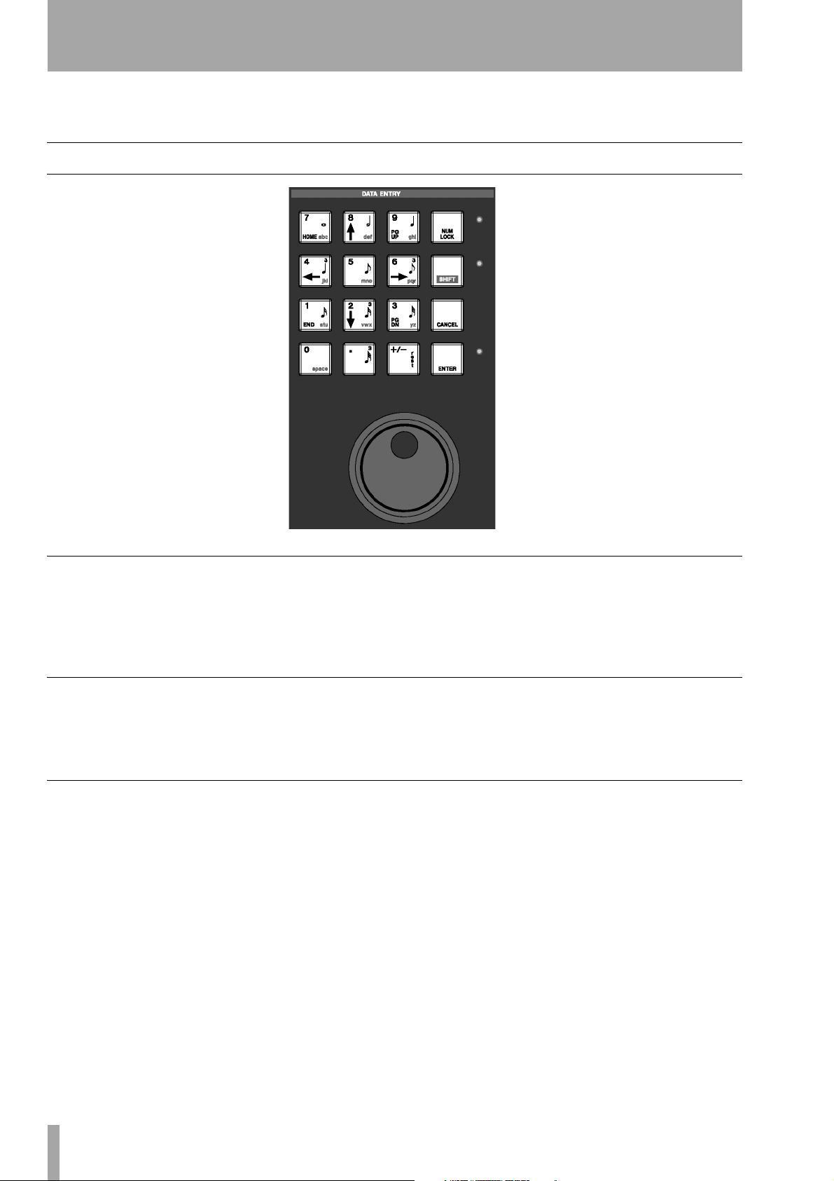
Data Entry
Only the Keypad is actually labeled DATA ENTRY.
The Keypad is used for entering numbers and letters
directly into a text field, and enabling the Shift func-
Keypad
The Keypad has four distinct uses, which change
according to the LCD’s current display screen and
selected text or number field. These are: cursor control (navigation), numeric, note value, and alphabet
character entry. Four ancillary keys support these
uses:
NUM LOCK, SHIFT, CANCEL, and ENTER.
Numeric Entry When the cursor is in a value field
(in the LCD screen only), the Keypad enters
numbers.
Navigation Function For the LCD screen, the
Keypad’s navigation keys (the up/down and left/
and then press the multi-function key to reach its secondary function. Think of the
shift key of a standard PS/2 keyboard—it serves a
similar purpose.
tion (as described above), up/down and left/right cursor navigation, and entering MIDI step record note
values.
right arrows) let you move the cursor between text
fields, scroll through menus, and select objects.
SHIFT key just like the
Note Value Entry In the MIDI Step Record
mode, in both the LCD and VGA Step Record
screens, the keys with notation marks let you quickly
assign note values to your stepped MIDI notes.
Character Entry On the LCD screen, when the
cursor is in a text field, the Keypad enters letters
(like a push-button telephone, where subsequent key
presses cycle through the letters listed on the keys).
After entering a letter, the cursor will, after a small
delay, autoadvance to the next space.
12 TASCAM SX-1 Reference Manual
Page 13
Ancillary Keys
Part I–Manuals & Conventions
NUM LOCK Use the NUM LOCK key to fix the
Keypad’s operation to only enter numbers.
SHIFT For front panel keys that have a Shift func-
tion, press the
Shift key is also a part of a number of special multiple-key commands (see “PS/2 Keyboard & Mouse
Shortcuts” on page 195).
TIP
An example of a handy multiple-key command is the
ability to copy your main mix to the cue mix. By holding
down
SHIFT
SHIFT key to enable this function. The
and pressing the
CUE
key (to the right of
Jog/Shuttle Wheel
The Jog/Shuttle Wheel is used for moving the trans-
port back and forth.
Jog Dial Jogging is controlled by the inside dial of
the Jog/Shuttle control. Spin the dial clockwise to
play audio and MIDI forward, and spin the dial counterclockwise to play audio and MIDI backwards.
Playback speed is determined by how fast you spin
the Jog Dial. (The Jog Dial is sometimes referred to
as the Scrub Wheel, and similarly, jogging is sometimes called scrubbing.)
the Virtual Channel knobs) you can copy the Master L/R
mix to the Cue layer. This move can save valuable time
when you need to quickly create a mix for an overdubbing musician.
CANCEL Use the CANCEL key to terminate an
action. This key is also part of a number of multiplekey shortcuts. For example, holding down
CANCEL
and touching a fader or other control will set that
control to default.
ENTER Use the ENTER key to complete an action.
Shuttle Wheel Shuttling is controlled by the out-
side ring of the Jog/Shuttle control. Turn the wheel to
the right to shuttle audio and MIDI forwards in time,
and turn the wheel to the left to shuttle audio and
MIDI backwards. How far you push the wheel, left
or right (backwards and forwards, respectively),
determines the speed of playback. The wheel is
spring-loaded, and upon release it pops back to center position and normal play speed.
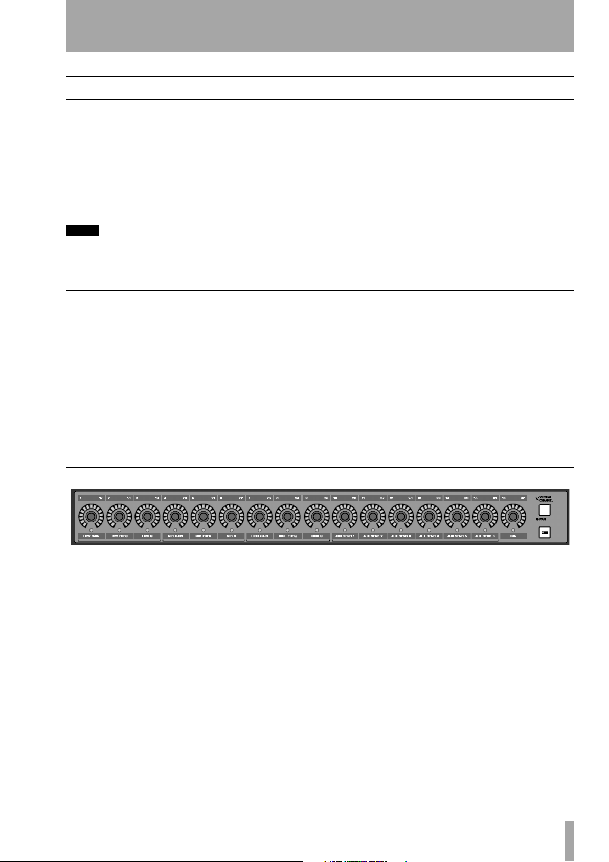
Virtual Channel Pots
The knobs at the top of the channel strips (above the
faders) are multi-function, infinitely rotating potentiometers (pots for short).
Depending on their currently selected mode
(accessed by the
keys), these controls serve as pan pots for all chan-
PAN/ VIRTUAL CHANNEL or CUE
nels, EQ, Aux sends and pan for a selected channel,
or pan for the Cue Mix. The virtual pots are surrounded by a ring of LEDs, which indicate their current setting. For example, a pan pot that is hard left
will have its far left LED illuminated, or an AUX
send that is full open will have all of its LEDs lit.
TASCAM SX-1 Reference Manual 13
Page 14
Part I–Manuals & Conventions
Fader Banks
It’s important to remember that the SX-1’s faders
control more than just one group of levels. Besides
the first 16 mixer channels, at default the faders also
control: inputs 17-32, the cue mix, MIDI tracks,
sends, returns, and busses. Different groups of faders,
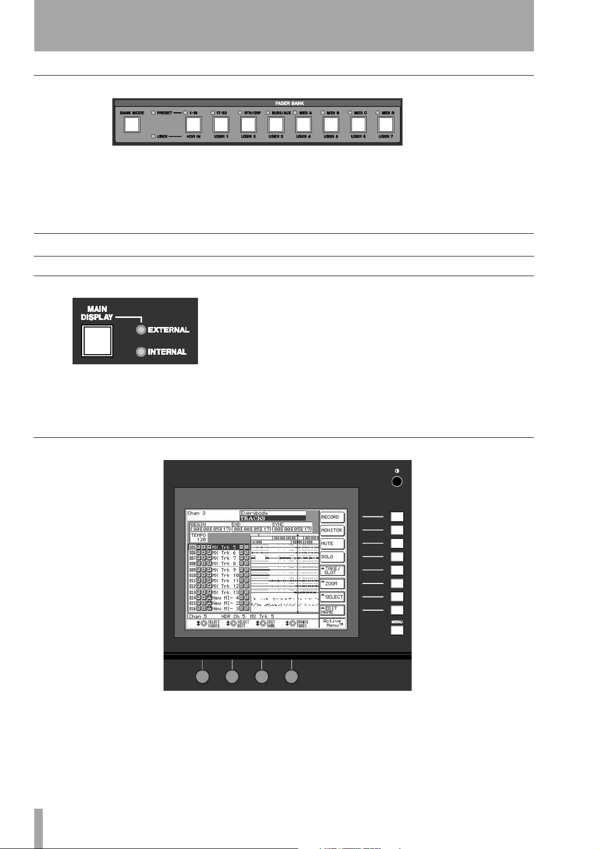
LCD Display
VGA or LCD
You have a choice of using the LCD or an VGA display as your main screen. The LCD display always
follows the selection keys in the
MODES
section. To have an external VGA follow
LCD Navigation
MAIN DISPLAY
called fader banks, are accessed by the keys in the
FADER BANKS section on the SX-1’s slanted front
panel, and the cue mix bank is reached via the
key to the right of the virtual channel strip.
these keys, press the
LCD ACCESS section (on the SX-1's slanted front
panel). The
<EXTERNAL> LED should light.
MAIN DISPLAY key above the
CUE
The LCD display is surrounded by several knobs and
buttons. The function of these controls change
according to the display on the LCD. We refer to
these controls as “soft” knobs and keys because their
functions are directly related to the SX-1's software.
14 TASCAM SX-1 Reference Manual
The soft knobs and soft keys line up with onscreen
knobs and keys to indicate their current function.
Each of the LCD’s screens has a different set of these
virtual controls. Some keys are single function while
others are of a pop-up menu style. Most of the soft
Page 15

Part I–Manuals & Conventions
knobs, upon turning, display a selection of choices in
a pop-up style menu.
To scroll up/down and left/right in an LCD window,
use the up/down and left/right arrow keys of the
Common Soft Knobs & Keys
There are several soft knobs and keys which are
common to many of the LCD screens. How these
controls operate are always identical, even if the
parameters they adjust, or select, are different.
Soft Keys
ACTIVE MENU
Arrow Icon
NAME
DELETE
OK or ACCEPT
COMPARE
CANCEL
CLEAR
SELECT
CURSOR -->
<-- CURSOR
BACK SPACE
Notes
SET TO DEFAULT
This virtual key toggles the LCD screen’s soft key menu bar on and off in order to expand the visible screen area (this
is not necessary for all screens).
When you see an arrow icon on a virtual key, pressing its associated soft key will open a menu.
Opens a dialog for naming the currently selected field.
Removes last entry.
Enters current field’s new value.
Press this key to compare your current settings with your last saved settings.
Escapes current action.
Clears entire field.
Opens parameter selection menu.
Moves cursor right.
Moves cursor left.
Moves cursor back one space.
A field to write text in that is saved with the patch.
This sets the associated controller’s value back to its factory default value.
ACTIVE MENU
Numeric Keypad. And to adjust the viewing angle
and contrast of the LCD, use the small knob to
the top right of the LCD.
TIP
HOT TIP! —
Explaining the common virtual knobs and keys here
means that not every soft key and knob is explained for
every LCD menu. If you are looking at an LCD menu and
don’t see all the items explained next to the manual’s
illustration, the missing controls are likely explained
here.
is always tied to the
MENU
soft key (the very bottom soft key).
Soft Knobs
CURSOR
EDIT NAME
CHANGE CHAR
SELECT (PARM or
OP)
DEST
IMPORT
Moves the cursor.
Opens change name menu.
Scrolls through characters.
Opens parameter selection menu.
Opens destination assign menu (for example, where the track will return).
Opens an import dialog from which you can bring settings from other projects into your current project.
VGA Display
Screen Navigation
Getting around on a connected VGA Display is just
like using a regular computer because the same
mouse and PS/2 keyboard rules apply. For example,
use the mouse to click on a field and open a pulldown menu, or enter names and values in text fields
with the PS/2 keyboard.
NOTE
Where Windows machines typically use the Control key,
and Macintosh systems use the Comand key with other
keys as keyboard shortcuts, the SX-1 uses the Alt key
together with other keys for this purpose.
TASCAM SX-1 Reference Manual 15
Page 16
Part I–Manuals & Conventions
A Main Menu Bar at the top of the VGA display
allows access to all of the SX-1’s screens and many
primary functions. Just like with a wholly computer
based application, you can use the Main Menu Bar to
change windows, select editing tools, save projects,
Tracks Display
and set preferences. But unlike a wholly software
based computer device, the SX-1 also gives you real
world hardware control of its software right from its
front panel.
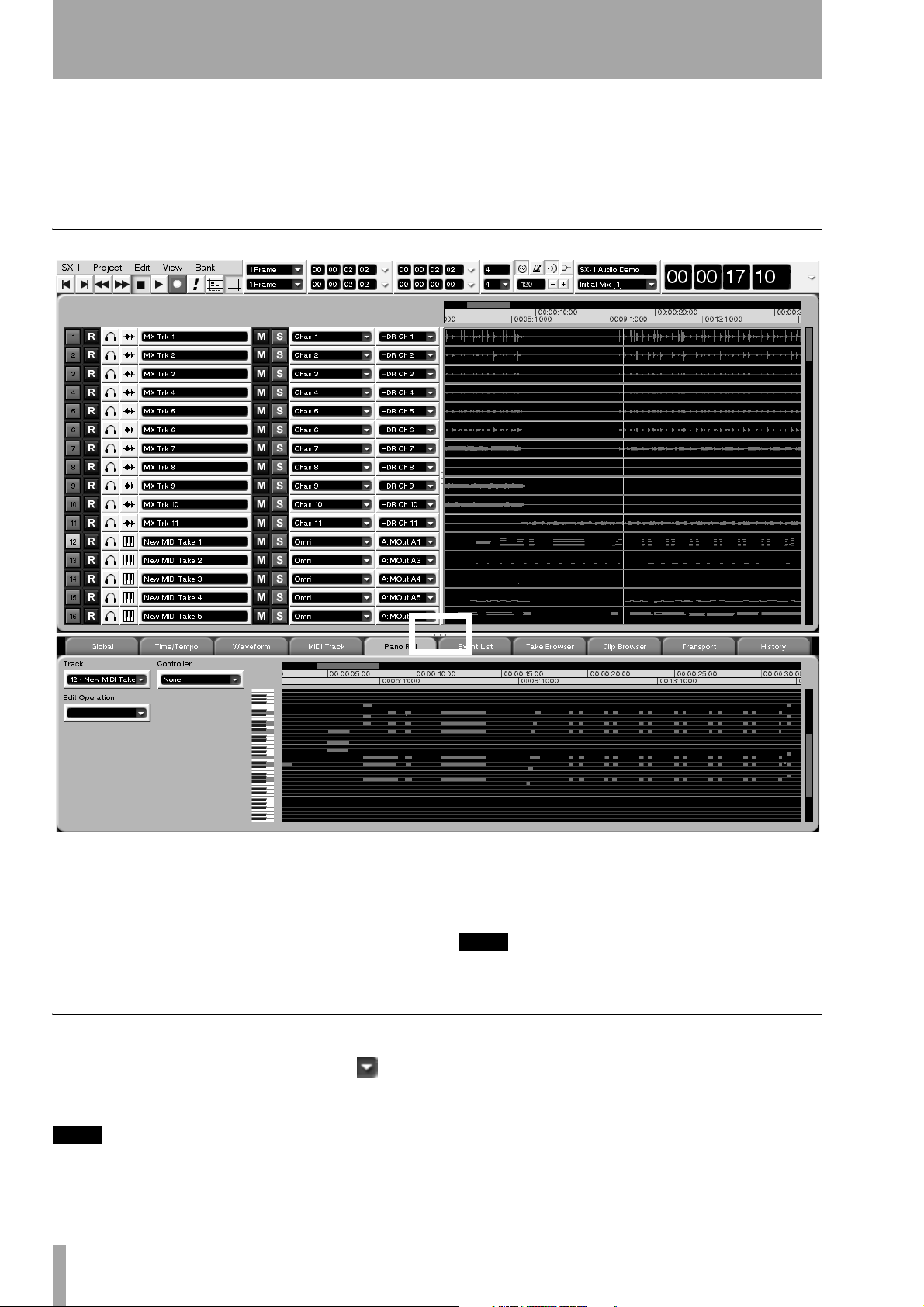
The SX-1 has many different VGA screens that you
will use over the course of a project. However, the
Track screen (pictured here) is possibly the most com-
monly accessed screen. Here, you will find a number
of essential elements for working with and managing
your project. You can get a clear picture of all the
tracks in your project and perform a variety of tasks
Mouse Conventions
Pop-Up Menus Click on the arrow icon ( )
next to a control (this might be anything, from a text
field to a button) to display pop-up menus.
TIP
If clicking normally on an arrow only selects the control,
but doesn’t let you edit it, try right-clicking on it.
16 TASCAM SX-1 Reference Manual
including: creating audio and MIDI tracks, assigning
takes, selecting regions for editing, arming and soloing mixer channels, and choosing editing and preference tabs.
TIP
To see the other nine main VGA screens, press ALT plus
a number key from 0-9 on the connected PS/2 keyboard.
Resizing Windows The Tracks and tabs areas
can be resized by clicking and dragging on the three
dots on the divider bars (as shown above). Click and
drag horizontally to resize the Tracks area, and click
and drag vertically to resize the tabs area.
Page 17
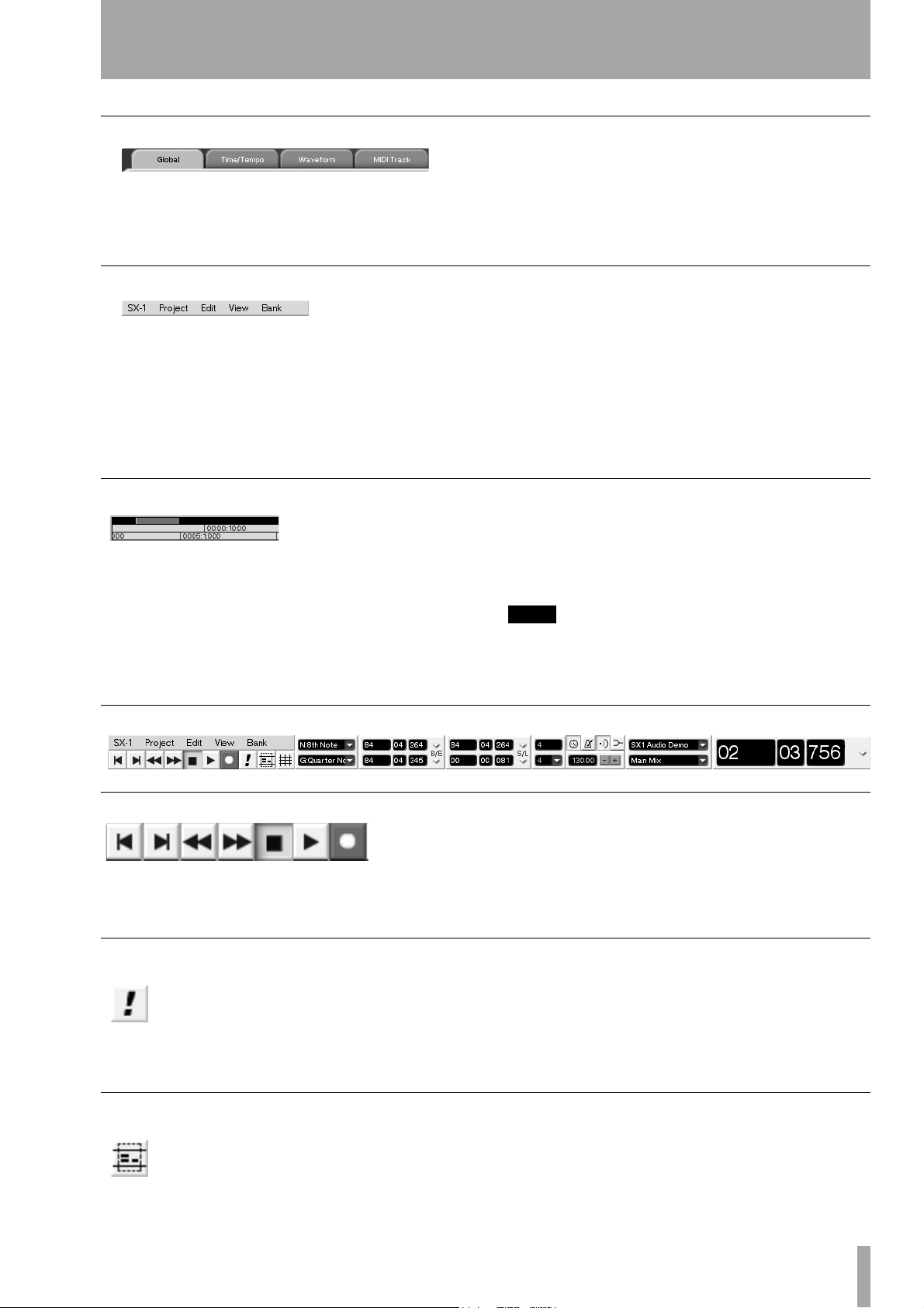
Ta bs
Part I–Manuals & Conventions
To reach the various layered operations windows in
different screens, click on their labeled “tabs” (just
like flipping through folders in a file cabinet).
Main Menu Items
To open the main menu items on the menu bar, click
once on an item.
Then drag the mouse downward over the pop-up
menu to make your selection. The menu items’
respective commands are covered throughout this
manual (for example, the
SX-1 commands, which are
Zoom & Scroll
Right click and drag over the gray horizontal bar
above the timeline (in the
screens, and respective
to zoom in or out. Left click and drag the gray bar to
scroll, horizontally (in time), through the project.
And, left clicking to the left or right of the gray bar
TRACK and AUTOMATION
Waveform and Audio Track tabs)
Tabs without a label are unassigned.
system oriented, are addressed in “System Settings”
on page 182, while the
Edit commands are covered in
the chapters on editing audio and MIDI regions—
“Audio tracks” on page 122 and “MIDI Sequencing”
on page 133).
moves the playhead back or forward, respectively, by
one screen.
TIP
You can zoom in or out on the VGA screen by pressing
Alt and the [ ] keys. Additional key commands and
shortcuts are listed in Appendix 2.
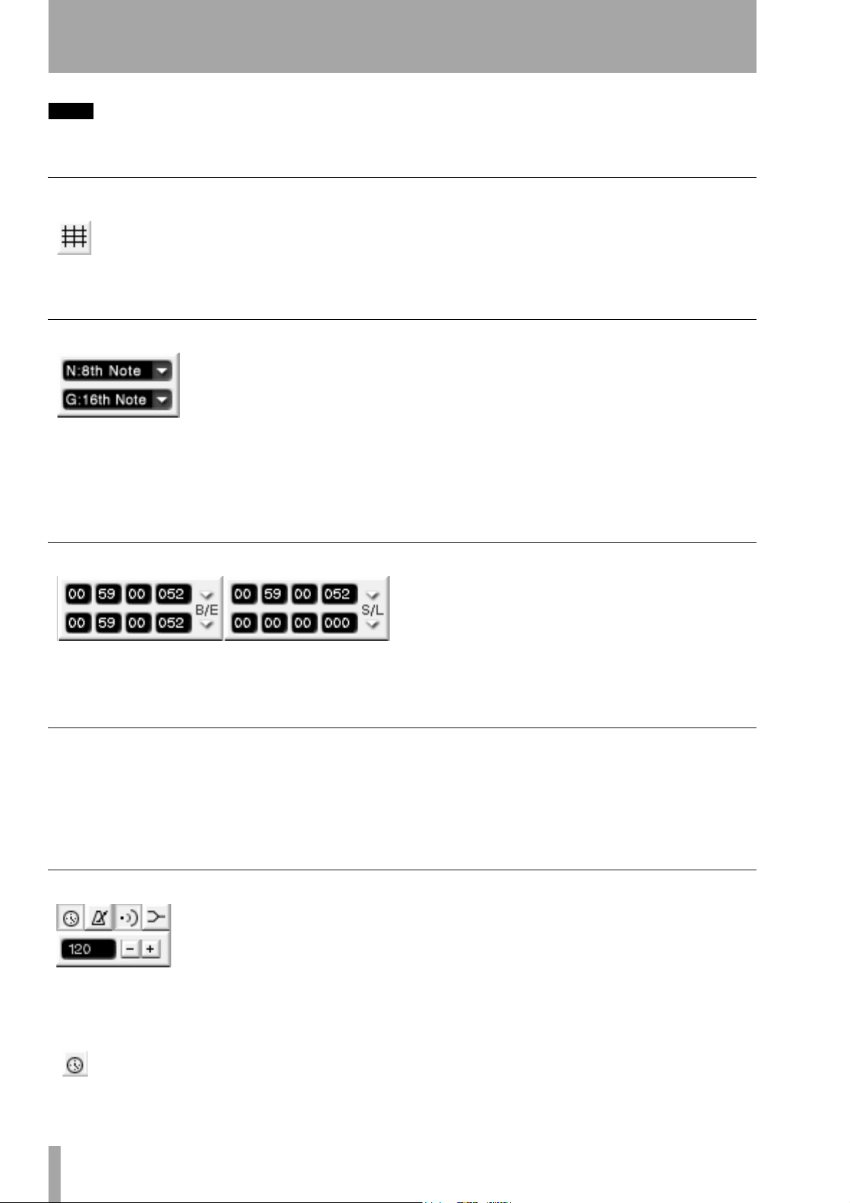
Main Menu Bar Elements
Transport & Record Keys
These keys mirror the SX-1’s hardware Transport
and Record Keys.
MIDI Panic
Use this button or the hardware PAN IC key
to clear stuck MIDI notes and other such
MIDI log jams (it sends All Notes Off messages, and then Note Off messages on all
channels) as well as dimming the audio outputs by
Tool Select
Press this button to choose a cursor selection tool. There are four choices: Region,
Event, Pencil, and Curve (the tools’ func-
They can be used in place of their hardware counterparts if desired.
20dB and stopping the transport. This is a latching
button, and the front panel
PANIC indicator pulses
while the panic mode is active. Press either the soft
PANIC button or the hardware PANIC key to exit the
panic mode.
tions are explained in “Essential Tools” on
page 122).
TASCAM SX-1 Reference Manual 17
Page 18
Part I–Manuals & Conventions
TIP
You can use the PS/2 keyboard’s Escape key to choose
the tool.
Grid Select
Use this button to toggle the “snap-to-grid”
feature on and off. The grid is represented
by vertical lines that intersect the tracks in
the
Tracks screen (they also appear in other
related screens, such as the VGA
Waveform tab). When
Nudge & Grid Settings
The top field (designated by N) adjusts your nudge
amount. Select an event (audio or MIDI) and use a
connected PS/2 keyboard’s +/- keys to move the
event forward or backward in time by the Nudge
value.
Edit Length Grids
snap-to-grid is on, events (audio and MIDI) will
always align to the nearest grid intersection when
moved by the mouse. When the grid is off, events are
not constrained to the grid lines.
The bottom field (designated by G) sets your “snapto” grid size (as described above). Both values can be
either SMPTE, hours:minutes:seconds,
bars:beats:ticks, feet:frames, or samples.
The left displays show a selection’s Edit In and Out
points. The top right display shows the selection’s
sync point, while the bottom right display shows the
Time Signature Selector
The top value represents the number of divisions in a
bar (the beats per measure). Almost any value can be
entered directly into this field from a connected PS/2
keyboard. The bottom value represents the type of
note assigned to the bar divisions (the note that
Tempo & Click Management
These buttons are for adjusting the project’s tempo
and click, and enabling or disabling MIDI echo and
merge.
Use this button to toggle the current
project’s Conductor track on and off. The
Conductor track contains the project’s
selection’s length. Readouts for each display can be
in SMPTE, hours:minutes:seconds, bars:beats:ticks,
feet:frames, or samples.
equals one beat). This value is chosen from the pull
down menu (click on the arrow). Note values range
from a whole note (semibreve) to a 64th note (hemidemisemiquaver).
tempo map and can be viewed and edited (using the
appropriate function—“Tempo Change” on
page 164). When the button is depressed, the
project’s tempo follows the Conductor track. When
the button is up, tempo follows the Main Menu Bar’s
18 TASCAM SX-1 Reference Manual
Page 19
Part I–Manuals & Conventions
tempo setting (the field to the left of the “-/+” keys,
pictured to the left and described below).
This button turns the MIDI metronome on
and off.
This button turns MIDI echo on and off.
This button turns MIDI merge on and off.
Project & Mix Menus
The top field displays the name of your current
project. If you click the arrow in this field you can
display the remaining record time (for the drive that
the current Project is loaded on). The bottom field
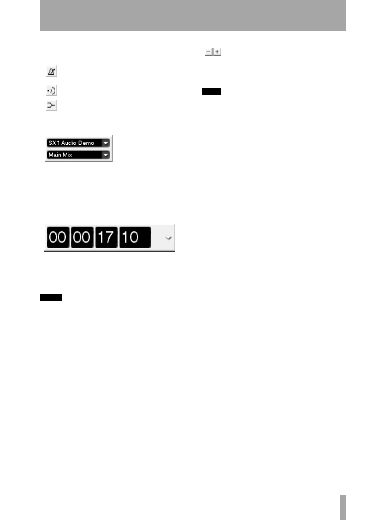
Main Time Code Display
Use these buttons to adjust a project’s
tempo when the Conductor track is not
enabled. A value can also be entered
directly into the adjacent tempo field from the PS/2
keyboard.
TIP
To learn more about MIDI functionality, see Part VII.
shows the name of your current Mix (the SX-1
allows multiple mix files to be associated with a
project). Mixes are managed from the VGA’s
Automation screen.
in the
Mix Tab
This Time Code display mirrors the SX-1’s main
LED Time Code display on its slanted front panel. It
can display time in SMPTE, hours:minutes:seconds,
bars:beats:ticks, feet:frames, and samples.
NOTE
Changing this field changes all of the registers in both
user interfaces - except the Nudge and Grid values. You
can think of this control as a sort of “master display
type” if you wish. After changing the view type to
another of the choices, you can always change any of
the individual fields to display whatever you like.
This parameter can also be changed by holding the surface
SHIFT
key and pressing the
on the slanted front panel - repeated pressings will
scroll through the available four choices
MAIN DISPLAY
key
TASCAM SX-1 Reference Manual 19
Page 20

Part I–Manuals & Conventions
Common buttons
There are several virtual keys (buttons) that are common to many of the VGA screens and tabs. How
these controls operate are always identical, even if
the parameters that they adjust, or select, are different.
Name field
NEW
RECALL
STORE
DELETE
DONE
EDIT NAME
Library
Notes
COMPARE
IMPORT
SET TO DEFAULT
Displays the name of the currently selected parameter or item. You can also change an item’s name by
entering text directly into this field and pressing
Creates a new entry for the currently selected parameter or item.
Restores from memory the currently selected (highlighted) parameter or item.
Saves to memory the currently loaded parameter or item.
Deletes the currently selected (highlighted) parameter or item.
This key is found in all Edit Operations screens. Press the key to complete the edit operation.
Enables you to change the name of the currently selected patch or preset.
A field where the names of the Library presets appear.
A text field where notes can be saved along with the preset.
Press this key to compare your current settings with your last saved settings.
Opens an import dialog from which you can bring settings from other projects into your current project.
This sets the associated controller’s value back to its factory default value.
NOTE
Explaining the common VGA buttons here means that
not every virtual key is explained for every VGA screen
and tab. If you are looking at an VGA display and don’t
see all the items explained next to the manual’s illustration, the missing controls are likely explained here.
ENTER
on the
Keypad
.
20 TASCAM SX-1 Reference Manual
Page 21
Part II– Monitoring Signals and Selecting Screens
Chapter 3 – Monitoring Audio
Output Control
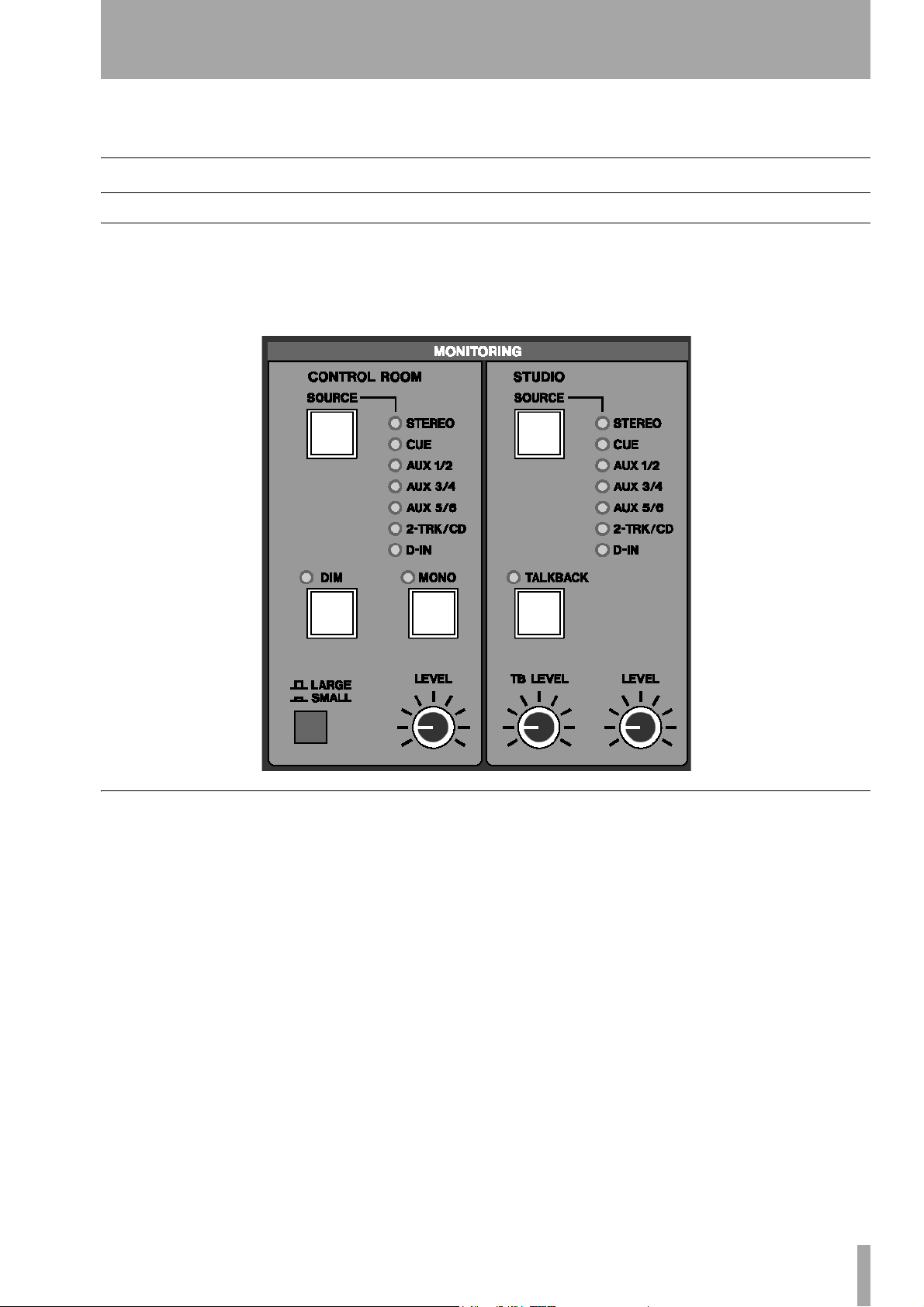
Monitor Section
This section houses controls for the Control Room
and Studio monitor outputs (these connections are on
the SX-1’s top panel).
CONTROL ROOM
This section provides controls for the Control Room
monitor outputs.
SOURCE Select The SOURCE key allows you to
choose the source signal that you want to monitor
through your Control Room speakers. Multiple
presses of this key allow you to toggle through the
following sources:
<STEREO> When the <STEREO> LED is illumi-
nated, the source monitored is the Master L/R output
(post the Master Fader).
<CUE> When the <CUE> LED is on, the source
monitored is the Cue mix.
<AUX 1/2> When the <AUX 1 / 2> LED is on, the
source monitored is the Aux 1 and 2 sends.
<AUX 3/4> With the <AUX 3 / 4> LED illuminated,
the source monitored is the Aux 3 and 4 sends.
<AUX 5/6> When the <AUX 5 / 6> LED is on, the
source monitored is the Aux 5 and 6 sends.
For the Aux sends, pressing once will select the oddnumbered aux send of the pair (the light will flash in
a single pattern) and pressing again will select the
even-numbered aux send (the light will flash in a
double pattern).
< 2 -TRACK/CD> When the <2 -TRACK/ CD> LED
is on, you are monitoring the signal coming into the
2TRIN stereo input (located on the unit’s top panel).
<D-IN> With the <D- IN> LED illuminated, you are
monitoring the unit’s digital inputs (found on the
unit’s rear).
Press once for
pattern), and press twice for
flash in a double pattern).
D-IN 1 (the light will flash in a single
D-IN 2 (the light will
TASCAM SX-1 Reference Manual 21
Page 22

Part II–Monitoring Signals and Selecting Screens
TIP
When the Aux sends are linked for stereo operation,
pressing
channels as a stereo pair. If the Aux sends are not
linked, pressing
and then the even Aux channels of a pair.
SOURCE
SOURCE
accesses both the odd and even Aux
will first monitor the odd,
Monitor DIM Press the DIM key to momentarily
lower the output level of your Control Room Monitors by a set amount. The default is –12 dB, but this
value can be as much as –50 db. The attenuation
amount is adjusted from the LCD
SHIFT+SETTINGS/ PREFS). This is a “smart” key.
(
TIP
When monitoring at levels that make having a conversation difficult, use
having to touch the master output levels.
DIM
to get a quick word in without
PREFERENCES screen
STUDIO Section
This section provides controls for the Studio monitor
outputs (which can be used to feed a set of speakers
in the tracking room) and the Talkback mic.
SOURCE Select The SOURCE key allows you to
choose the source signal that you want to monitor
through your Studio speakers. Multiple presses of
this key allow you to toggle through the following
sources:
<STEREO> When the <STEREO> LED is illumi-
nated, the source monitored is the Master L/R output
(post the Master Fader).
<CUE> When the <CUE> LED is on, the source
monitored is the Cue mix.
<AUX 1/2> When the <AUX 1 / 2> LED is on, the
source monitored is the Auxiliary 1 and 2 sends.
MONO Select Press MONO to hear the source
currently selected in mono (instead of stereo). The
key is of a “smart” type.
Speaker Select The Speaker Select switch,
labeled
between two different sets of speakers (for example,
large and small control room monitors). The
and SMALL speaker connections are located on the
top panel of the SX-1.
LARGE/ SMALL, lets you quickly switch
LARGE
Monitor LEVEL The LEVEL knob controls the
volume of your control room monitors. You can preset the control’s starting level (if for instance, the initial output seems too loud) from the LCD
PREFERENCES screen (SHIFT+SETTINGS/ PREFS).
The default output is +4dBu.
<AUX 3/4> With the <AUX 3 / 4> LED illuminated,
the source monitored is the Auxiliary 3 and 4 sends.
<AUX 5/6> When the <AUX 5 / 6> LED is on, the
source monitored is the Auxiliary 5 and 6 sends.
For the Aux sends, pressing once will select the oddnumbered aux send of the pair (the light will flash
slowly) and pressing again will select the even-numbered aux send (the light will flash quickly).
<2 -TRACK/CD> When the <2 -TRACK/ CD> LED is
on, you are monitoring the signal coming into the
2TRIN stereo input (located on the unit’s top panel).
<D-IN> With the <D-IN> LED illuminated, you are
monitoring the unit’s digital inputs (found on the
unit’s rear).
Press once for
and press twice for
quickly).
D-IN 1 (the light will flash slowly),
D-IN 2 (the light will flash
TALKBACK Select
The TALK BAC K key engages the Talkback mic
located on the left side of the SX-1’s slanted front
panel. Use the Talkback mic to communicate with
musicians and other talent over the Studio outputs.
The
TALK BAC K key, together with the MONO and
DIM leys, is a “smart” key. Press and release these
keys briefly to latch them on and off. Press and hold
22 TASCAM SX-1 Reference Manual
them for longer before releasing to use them as nonlatching keys.
TIP
When the
TALBACK
SHIFT
key is held together with the
key, the
TALK BAC K
key acts as a slate key.
Talkback Level The TB LEVEL knob adjusts the
volume of the Talkback mic.
Page 23
Part II–Monitoring Signals and Selecting Screens
Monitor Level
This LEVEL knob controls the volume of your Studio
monitors.
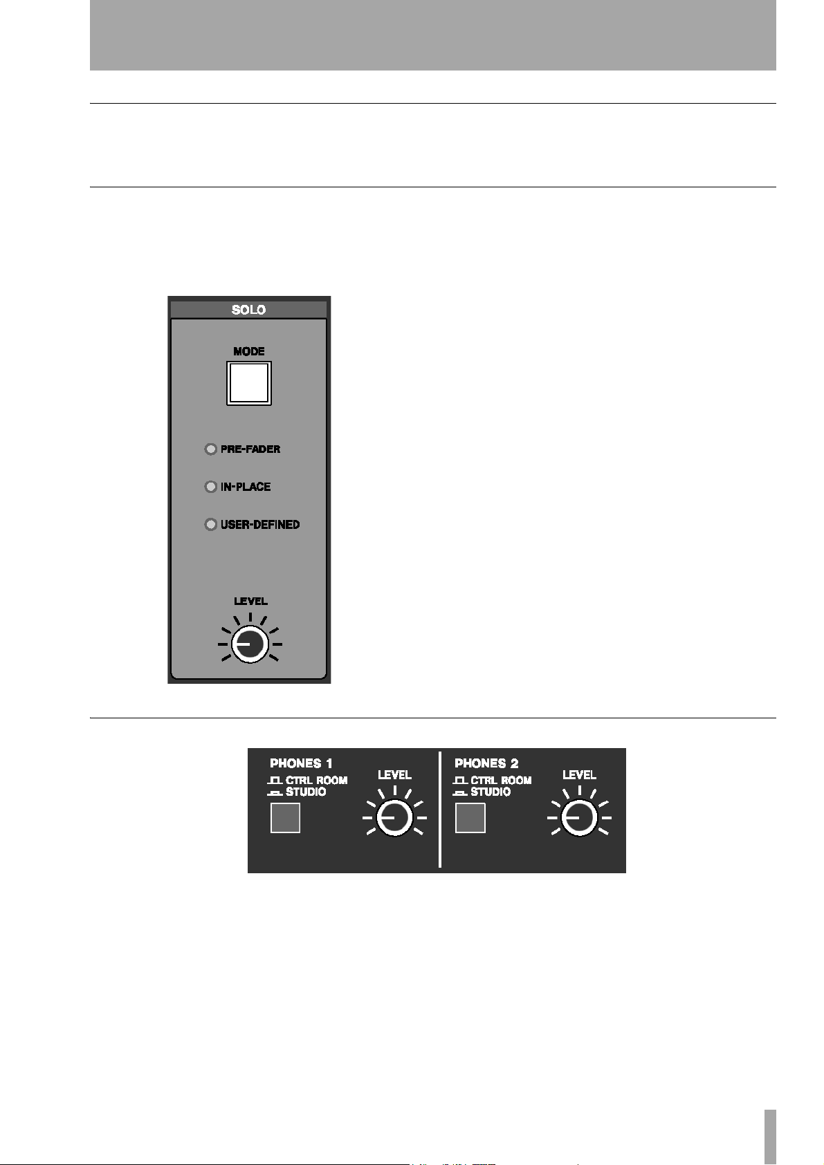
SOLO Section
This section contains controls for the mixer’s Solo
function. Pressing the
Fader engages the solo mode for the Channel Strip’s
MUTE keys.
SOLO key on the Master
MODE Select The MODE key lets you choose
how the SX-1's solo function will operate. There are
three options:
<PRE-FADER> When the <PRE- FADER> LED is
illuminated, the Pre-Fader solo feature is engaged.
This lets you solo a source at its input, before it
reaches a channel’s gain stages. The pre-fader output
is sent out of the Solo buss.
<IN-PLACE> When the <IN-PLACE> LED is on, the
In-Place solo feature is engaged. This feature allows
a soloed signal to retain the same settings as heard in
the main mix (this is accomplished by muting everything going to the Master L/R buss except the soloed
channel).
<USER-DEFINED> In operating system (OS) Ver-
sion 1.0. when the
the solo mode monitors signal directly after the fader
(After Fader Level). Signal is fed to the Solo buss
without effects. In future OS revisions, the UserDefined feature will be expanded to include a number of enhancements.
<USER-DEFINED> LED is on,
HEADPHONES
This section contains level and source controls for
the two separate headphone outputs found on the SX1’s top panel.
PHONES 1 The CTRL ROOM/ STUDIO key selects
whether Headphone 1 receives the Control Room or
Studio mix.
Solo LEVEL This [level] knob controls the level of
the Solo buss, and hence the volume of the Solo output in PFL and AFL modes (pre-fader and after-fader
levels).
LEVEL 1 This LEVEL knob controls the volume for
Headphone 1.
PHONES 2 This CTRL ROOM/ STUDIO key
selects whether Headphone 2 receives the Control
Room or Studio mix.
LEVEL 2 This LEVEL knob controls the volume for
Headphone 2.
TASCAM SX-1 Reference Manual 23
Page 24

Part II–Monitoring Signals and Selecting Screens
TRANSPORT SOLO
The keys in this section provide a way to globally
solo individual components (like the HDR or the
Sequencer) of your studio with a single button press.
HDR Press HDR to hear just the hard disc recorder.
All other audio inputs to the console will be muted.
SEQ Press SEQ to hear just the MIDI sequencer.
The HDR tracks will be muted.
EXTERNAL Press EXTERNAL to hear an external
device that is slaved and has its audio outputs connected to the SX-1.
24 TASCAM SX-1 Reference Manual
Page 25
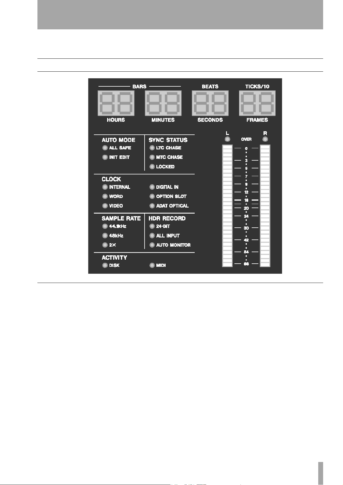
Chapter 4 – Metering & Indicators
Reading LED Meters
Part II–Monitoring Signals and Selecting Screens
Master Meter Section
This section houses the main Time Code display,
master L/R LED meters, and a variety of indicator
LEDs illustrating the SX-1’s current state.
LED Time Code Display The Time Code dis-
play shows either hours:minutes:seconds:frames or
bars:beats:ticks, feet:frames and samples.
Changing the Time Code Display’s readout can be
done from the VGA's
or by holding the surface
MAIN DISPLAY button on the slanted front panel.
Main Menu Bar Time Code Display,
SHIFT key and pressing the
AUTO MODE These LED indicators reflect the
SX-1’s current automation status.
<ALL SAFE> Indicates that automation will not be
recorded.
<INIT EDIT> Indicates that the automation system is
in Init Edit mode.
SYNC STATUS These LED indicators reflect the
SX-1’s current synchronization state.
<LTC CHASE> Indicates that the SX-1 is chasing
incoming Longitudinal Time Code (LTC).
<MTC CHASE> Shows that the SX-1 is chasing
incoming MIDI Time Code (MTC).
<LOCKED> Indicates that the SX-1 is locked to
incoming time code.
CLOCK These LED indicators reflect the SX-1’s
current clock status.
<INTERNAL> Indicates that the SX-1’s internal
clock is the master clock source.
<WORD> Shows that incoming Word Clock is the
master clock source.
<VIDEO> Shows that incoming video sync is the
master clock source.
TASCAM SX-1 Reference Manual 25
Page 26

Part II–Monitoring Signals and Selecting Screens
<DIGITAL IN> Indicates that the digital input con-
nected to one of the rear digital input ports is the
master clock source.
<OPTION SLOT> Indicates that a device connected
to an optional card installed in one of the Option
Slots is the master clock source.
<ADAT OPTICAL> Shows that incoming ADAT
Optical (on the rear panel) is the master clock source.
SAMPLE RATE These LED indicators reflect the
SX-1’s current sample rate.
<44.1KHZ> Indicates that the current sample rate is
44.1 kHz.
<48KHZ> Indicates that the current sample rate is
48 kHz.
<2X> Shows that the current sample rate is one of the
two high sample rate settings (88.1 kHz or 96 kHz).
For example, at 88.2 kHz, both the 44.1kHz and 2X
indicators will light. High sampling rates will be
available in Version 2.
HDR RECORD These LED indicators reflect the
Hard Disk Recorder’s resolution, input and record
monitoring states.
<24 -BIT> Indicates that the SX-1 is set to record at
24-bit resolution.
<ALL INPUT> Shows that the All Input monitor
mode is selected.
<AUTO MONITOR> Shows that the Auto Monitor
mode is selected.
ACTIVITY These LED indicators display hard disk
and MIDI activity.
<DISK> Indicates that the hard drive is accessing.
<MIDI> Indicates the existence of incoming or outgo-
ing MIDI data. The actual operation depends on the
MIDI LED setting on the LCD
Preferences page.
Master Stereo Meter The Master Stereo Meter
provides a visual cue of your master output buss. It is
a 30-segment LED that goes from –60 to 0 dB and
features peak LED indicators to show digital “overs.”
TIP
To see discrete meters for each mixer channel, go to the
Overview
DISPLAY MODES
screen by pressing
section.
OVERVIEW
in the
MAIN
26 TASCAM SX-1 Reference Manual
Page 27
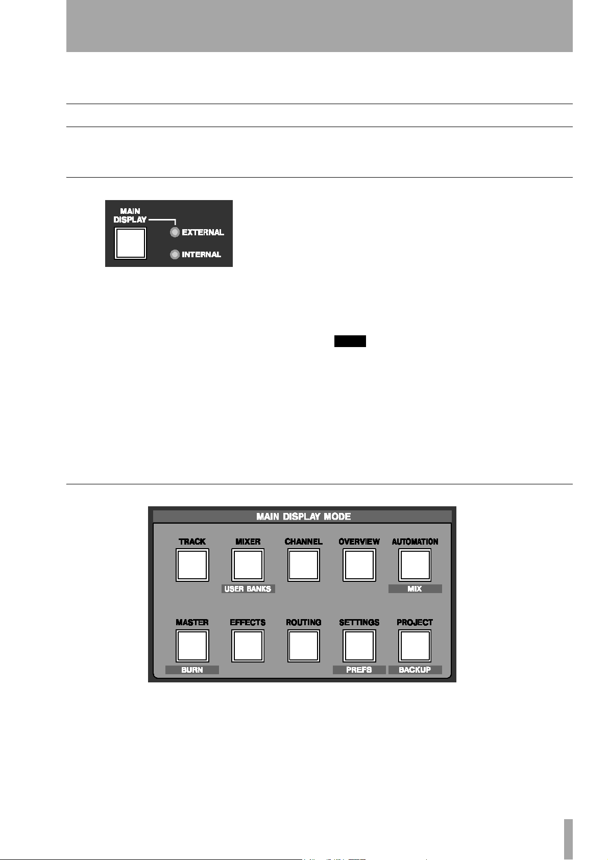
Part II–Monitoring Signals and Selecting Screens
Chapter 5 – Selecting Screens
Screen Controls
You have a choice of using the onboard LCD or a
connected VGA display as your main screen.
Main Display Key
The MAIN DISPLAY key selects between the SX-1’s
onboard LCD screen or an external VGA monitor as
your main display. The LCD always follows the
selection keys in the
MAIN DISPLAY MODES sec-
tion.
To have an external VGA follow these keys, press
MAIN DISPLAY and make the associated
<EXTERNAL> LED light. The LED indicator set-
tings are as follows:
<INTERNAL> When the <INTERNAL> LED is illu-
minated, the screens recalled by the keys in the
DISPLAY MODES
section appear on the LCD . If an
MAIN
VGA screen is connected, its display will not follow
MAIN DISPLAY MODE keys.
the
Main Display Mode Section
<EXTERNAL> When the <EXTERNAL> LED is on,
the screens recalled by the
MAIN DISPLAY MODES
keys appear on both the LCD and the external VGA
display at the same time.
TIP
VGA screens can also be changed, independently of the
LCD, by pressing ALT and a number key on a connected
PS/2 keyboard.
This option is available regardless of the
DISPLAY
The LCD also has its own set of dedicated controls in the
LCD ACCESS
key’s setting.
section.
MAIN
The controls in this section recall different screens.
These screens appear on both the LCD and a connected VGA display (when the
is set to
EXTERNAL).
MAIN DISPLAY key
TRACK The TRACK key recalls the TRACK screen,
where tracks are created and edited.
MIXER The MIXER key recalls the MIXER screen,
which shows a full console view on the VGA, along
with a channel-at-once view on the LCD.
CHANNEL The CHANNEL key recalls the MIXER
CHANNEL
for a selected channel.
screen, which shows all of the parameters
TASCAM SX-1 Reference Manual 27
Page 28
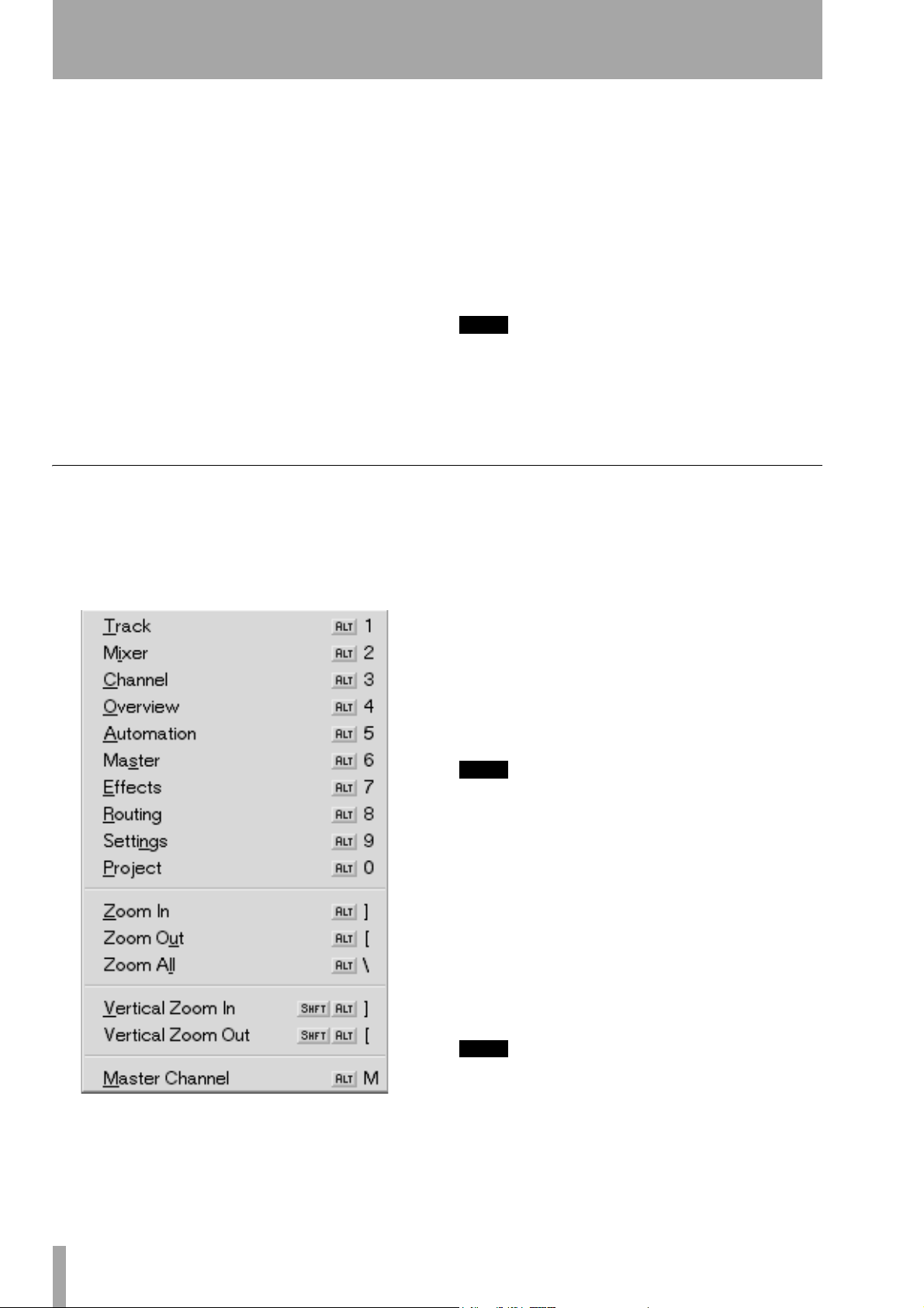
Part II–Monitoring Signals and Selecting Screens
OVERVIEW The OVERVIEW key recalls the
OVERVIEW screen, which can be used as a graphic
meter bridge.
AUTOMATION/MIX The AUTOMATION/ MIX
key recalls the
SHIFT+AUTOMATION/ MIX recalls the MIX screen.
AUTOMATION screen, and pressing
MASTER/BURN The MASTER/ BURN key recalls
the
MASTER screen where backup CD-Rs can be cre-
ated and managed.
EFFECTS The EFFECTS key recalls the EFFECTS
screen, where plug-ins are assigned to the SX-1’s
four effect quadrants.
ROUTING The ROUTING key recalls the ROUTING
screen.
View Menu
The VGA display’s menu bar also provides a View
menu, which mirrors the hardware keys of the
DISPLAY MODE
section. Zoom commands are also
available if you prefer an alternative to the click-anddrag zoom method.
MAIN
SETTINGS/PREFS The SETTINGS/ PREFS key
recalls the
trols for clock reference, and pressing
SETTINGS/ PREFS recalls the PREFERENCES screen
where a number of other settings can be stored (such
as meter ballistics).
SETTINGS screen which holds all of the con-
SHIFT +
PROJECT/BACKUP The PROJECT/ BACKUP
key recalls the
PROJECT/ BACKUP recalls the BACKUP screen.
TIP
The VGA screen can also be switched by pressing ALT
and a number key on the PS/2 keyboard. This option is
available regardless of the
setting.
PROJECT screen, and pressing SHIFT +
MAIN DISPLAY
key’s
Screen Recall Commands Each command
recalls its associated screen for the VGA. Explanations of these screens are found in the relevant chapters (such as, the
chapter that addresses automation, Chapter 12).
Automation screen is found in the
Zoom In Magnifies (zooms in) data horizontally,
relative to time, on the
screens, and “
Waveform” and Auto Track tab views.
TRACK and AUTOMATION
Zoom Out Expands (zooms out) data horizontally,
relative to time, on the
screens, and
TIP
Another way of zooming in and out is the ALT + [ ] PS/2
Keyboard command. Waveform height can also be
changed with SHIFT+ALT+[ ].
Waveform and Auto Track tab views.
TRACK and AUTOMATION
Zoom All Zooms all the way out to show the entire
project in the
Waveform and Auto Track tab views.
TRACK and AUTOMATION screens, and
Master Channel Recalls the Master stereo output
CHANNEL screen. This command is identical to press-
ing
CHANNEL from the MAIN DISPLAY MODE sec-
tion and then selecting the Master fader channel (by
pressing its
TIP
Each command’s associated PS/2 keyboard shortcut is
listed in the menu (right after the command’s title).
SEL key).
28 TASCAM SX-1 Reference Manual
Page 29
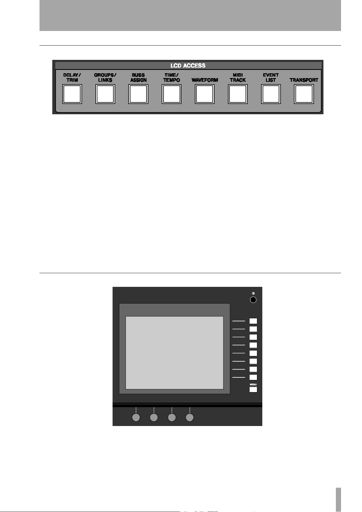
LCD ACCESS Section
Part II–Monitoring Signals and Selecting Screens
The controls in this section recall screens for the SX1’s LCD display. Many of these screens reflect the
tabs of the VGA screens (for example, the
Track
screen’s tabs).
DELAY/TRIM The DELAY/ TRIM key recalls the
Delay/Trim screen, which houses individual channel
delay and level trim controls.
GROUPS/LINKS The GROUPS/LINKS key recalls
the
Groups/Links screen, where fader groups and linked
parameters and channels are managed.
BUSS ASSIGNMENT The BUSS ASSIGNMENT
key recalls the
all buss routing for the console.
Buss Assignment screen, which handles
TIME/TEMPO The TIME/ TEMPO key recalls the
Time/Tempo screen, where a project’s Tempo and met-
ronome settings may be modified.
LCD Screen
WAVEFORM The WAVEFORM key recalls the
Waveform screen, where a selected channel’s sample-
accurate waveforms can be viewed and edited on the
LCD.
MIDI TRACK The MIDI TRACK key recalls the
MIDI Track screen which contains a Piano Roll display.
EVENT LISTS The EVENT LISTS key recalls the
Event Lists screen where individual events may be
viewed and edited.
TRANSPORT The TRANSPORT key recalls the
Transport screen where external devices are controlled,
locate points are managed , and parameters like
frame rate are set on the LCD.
The onboard LCD provides access to all the necessary operating screens. In situations where an external VGA display is not available, the SX-1’s
software components can be reached directly through
the LCD. The LCD can also work in tandem with the
VGA to provide a second display.
TASCAM SX-1 Reference Manual 29
Page 30

Part II–Monitoring Signals and Selecting Screens
LCD Contrast This knob adjusts the viewing
angle and contrast of the LCD screen.
Soft Keys The functions of these keys change
according to the current LCD screen.
MENU The MENU soft key is dedicated to turning
the soft keys’
ACTIVE MENU on and off.
Soft Knobs The functions of these knobs change
according to the current LCD screen.
30 TASCAM SX-1 Reference Manual
Page 31

Chapter 6 – Transport, Loop, Auto Punch
Transport Controls
Front Panel
Part III– Locate, Transport, & Surround
These keys provide standard tape-style transport controls for navigating through the currently loaded
project.
JUMP Back By default, the left JUMP key moves
the playhead to the the beginning of the first event in
the project. However, it is possible to set this
key to function differently. These settings are made
in the LCD
TRANSPORT screen (pictured below).
JUMP
JUMP Forward By default, the right JUMP key
moves the playhead to the end of the last event in the
project. However, it is possible to set this
to function differently. These settings are made on
one of the LCD’s
screen pictured below).
PREFERENCES screens (the TRANSPORT
JUMP key
LCD Jump Controls There are controls on the
LCD’s
ality.
TRANSPORT screen for setting Jump function-
JUMP KEY MODE The Jump Keys can operate in
one of 3 different modes:
FIRST LAST With this setting selected, the JUMP
Left key will locate the playhead to the beginning of
the first event in the project. The
will locate the playhead to the end of the last event in
the project (this is how the TASCAM MX-2424
works).
ABSOLUTE With this setting selected, the JUMP Left
JUMP Right keys jump to specific values. These
and
values are entered in the Jump Left and Jump Right
registers located directly below.
LCT POINTS With this setting enabled, the SX-1 will
scroll through all Locate Points stored in the project
in chronological order, upon repeated presses of the
JUMP keys, even if they are not sequentially num-
bered that way.
JUMP LEFT & JUMP RIGHT Settings entered here
will dictate where the playhead locates after a Jump
Left or Jump Right in Absolute Jump Mode.
JUMP Right key
Press
SHIFT, then, from the LCD ACCESS MODE
section, press
soft key to scroll to this screen.
SETTINGS/ PREFS. Use the NEXT PAGE
OFFSET This setting acts much like a pre-roll for the
Jump commands. If the value is anything other than
zero, the playhead will locate to the point dictated by
the Jump mode, adding or subtracting the Offset
value from the original location.
CUEING MODE This setting causes Fast Forward
and Rewind to operate audibly at up to a maximum
1.5 times the play speed while monitoring audio. The
effect is much like Scrub, and is useful for situations
when an external video deck is chasing the SX-1.
PLAY MODE This determines the behavior of the
transport after any locate operation. There are three
modes:
TASCAM SX-1 Reference Manual 31
Page 32

Part III–Locate, Transport, & Surround
Immediate In this mode, the SX-1 stops after any
locate operation.
Automatic In this mode, the SX-1’s transport will
immediately engage PLAY after any locate operation.
Deferred When the SX-1 is controlling external
devices, pressing PLAY during a locate operation
results in playback starting after the locate operation
is complete.
VGA Transport
Transport controls that mirror the front panel Tran s port Keys are available in the VGA screens’ Main
LCD Transport
A variety of external devices can have their transports controlled directly from the SX-1’s Transpo r t
Keys.
LOCATE POINTS Opens the screen where you can
manage Locate Points (“Locate Points” on page 38).
REGISTER Opens the REGISTERS screen where you
can view and adjust Loop, Autopunch, and Audition
points.
EXTERNAL DEVICES Use this screen to manage
the SX-1’s transport communication with external
devices.
REWIND This keym rewinds the project.
FAST FOWARD This key , fast forwards the
project.
STOP This key ª stops playback.
PLAY This key Á starts playback and punches out
of Record.
RECORD With a track record enabled and the trans-
port in PLAY, press this key º to punch in.
Menu Bar. The Record key displays an “M” when
Mixdown Mode is enabled.
FRAME RATE This knob sets the project frame
rate. Rates of 30, 29.97, 29.97 Drop, 25, and 24
frames per second (fps) are available. To change the
current frame rate, you must select
from the tab that appears at the right of the screen.
Accept or Cancel
SMPTE/TIMECODE OFFSET This parameter
determines the amount of offset from incoming and
outgoing timecode. Values can be entered by using
the keypad.
Turning the knob accomplishes two things: the knob
now acts as a cursor for the offset register (moving
the cursor from hours to minutes to seconds, for
instance), and it opens a dialog strip on the right side
of the LCD screen:
REC CHANNEL This parameter determines which
channel strip on the SX-1 will act as the first channel
for remote track arming. The above example has
Channel 17 set for this value.
32 TASCAM SX-1 Reference Manual
TOGGLE SIGN When this key is
pressed, the offset value changes from a
positive offset (
meaning that an offset of
would play back two seconds later than
the device generating the timecode, and
that an offset of
back two seconds earlier.
+) to a negative offset (-),
+00:00:02:00
–00:00:02:00 would play
CURSOR <--- Moves the cursor to the
left by one value.
CURSOR ---> Moves the cursor to the
right by one value.
SMPTE FORMAT This key toggles the offset dis-
play to show one of the four timecode choices available in the SX-1.
Page 33

Part III–Locate, Transport, & Surround
ZERO CURSOR This key clears any value that the
cursor is currently selecting.
ZERO ALL This key clears the contents of the entire
register.
ACCEPT Accepts the change.
CANCEL Declines the change.
ADD This key opens the ADD dialog. Use these
selections to add the devices you want to control
from the SX-1:
MMC OPEN Use this to add devices
that accept Open Loop MIDI Machine
Control Protocol to the list. This selec-
tion will be available in Version 1.5.
MMC CLOSED Use this to add
devices that require Closed Loop MIDI
Machine Control Protocol to the list.
This selection will be available in Version 1.5
ADAT Use this selection to create a device profile
for controlling a connected ADAT. This selection will
be available in Version 1.5.
EDIT This key opens the EDIT dialog:
RECS This selection sets the number of
record channels that a device supports
for remote track arming.
NAME With this selection you can
name the devices in your list.
CHASE MODE This key opens the CHASE MODE dia-
log. Use these selections to specify whether the SX-1
will operate as a master or slave, and the type of time
code it will generate or recognize:
NONE No time code is generated or
recognized.
LTC MASTER Specifies that the SX-1
will generate Longitudinal Time Code.
P2 This selection adds a generic P2
device. Generic transport, jog/shuttle
wheel and track arming is available. With Auto
Detect on, the SX-1 will sense from the P2 connection what kind of device is present, and should
update its display accordingly.
DTRS This selection will add a DTRS tape machine
(this family of machines includes the TASCAM DA88 and DA-78HR) to the list. This function will be
available in Version 1.5.
LTC SLAVE Specifies that the SX-1
will chase incoming Longitudinal Time
Code.
MTC MASTER Specifies that the SX-
1 will send MIDI Time Code out its
MIDI Out jacks. You can select the
MIDI ports that are used to send MTC.
This parameter is found in the
Tracks screen.
Global tab of the VGA
MTC SLAVE Specifies that the SX-1 will chase
incoming MIDI Time Code at its
MTC IN jack.
TASCAM SX-1 Reference Manual 33
Page 34

Part III–Locate, Transport, & Surround
P2 Remote Machine Control in the SX-1
The SX-1 has full support for the Sony P2 Protocol
for controlling video decks and other multitrack
audio devices. Together with the Transport SOLO
The Philosophy
The SX-1 will always try to send transport commands to the machine that is the current Timecode
Master. The settings in the Machine Control List (
TRANSPORT Screen) and the state of the Transport
SOLO keys determine which machine is the master.
The SX-1 will always contain 2 machines in this list,
i.e. the HDR and the Sequencer/Automation. For
simplicity, you are allowed to choose the Timecode
LCD
General SX-1 Transport Controls
The SX-1 has a number of transport controls that are
generally used for the internal HDR recorder and
sequencer, but which also work when an external
device is the Transport Master.
function, seamless video post-production edit integration is possible.
master/slave state of the HDR only, because the
Sequencer and Automation engine is always locked
to the HDR’s current time.
In order to use the P2 remote control port, it is necessary to add a machine to the 2 internal machines
already in the Machine Control List. This is possible
by manually adding a device, or using the auto-detect
feature of the SX-1.
• Main Transport Keys
• Locate buttons.
• Jog/Shuttle
• Auto Play Mode
• Cueing Mode
• Record Arms.
Customizing the Devices
It is possible to change the name of the device that
appears in the list, or if the Auto-Detect function is
used, the name will automatically be chosen to match
the detected device. Similarly, the number of Rec
Arm channels is user selectable, but auto-detect will
attempt to match the capabilities of the detected
device.
The Sony P2 protocol allows designating up to 4
tracks as Analog, and any number as digital tracks.
Most Analog VTRs only have 2 audio channels, so if
the number of Rec Arm channels is set to 2, the SX-1
will use Analog track commands to tell the external
device which channels to arm. 4 Channel devices are
also treated as analog, but once you select 8 or more
Rec-arm channels for a device, the P2 Digital channel Rec-Arm protocol will be used. Multi-track audio
recorders such as the Tascam DTRS and MX-2424
series use this extensively, but the DA-88 notably has
a programmable Rec-Arm assignment that includes a
hybrid analog/digital mix. Such a mixed setting will
be unusable with the SX-1, so set the DA-88 to use
all Digital P2 Rec-Arm designations.
If you have a device that has just 4 Digital channels,
you will need to set the device to 8 channels in order
to use the digital Rec-arm assignments in the P2 Protocol.
The user can specify which
SX-1 front panel starts the
each device. The Internal HDR, for example, defaults
to channel 17, because that is where the default routing places the return signal from the HDR. If the
starting channel places the last channel of the
selected device off the end of the front panel, then the
REC-arm assignment continues onto the next logical
bank, i.e. it wraps around. This is useful if you have a
MX-2424 selected that you wish to dump a whole
session to in real-time, you will always be able to
access all of the 24 record arm function buttons, even
though the front panel shows 16 at any one time.
Select the start channel according to where the first
signal from the external device is routed into the SX1’s mixer, or alternatively to the buss or channel
that’s direct out feeds the first audio input of the
external device.
If two machines overlap in their Rec-arm function
assignments, then the SX-1’s front panel channel
strips will show and operate the
REC-Arm button on the
REC-Arm functions of
REC-Arm belonging
34 TASCAM SX-1 Reference Manual
Page 35

Part III–Locate, Transport, & Surround
to the first machine in the Machine Control List that
contains that channel.
To customize a device, select it in the Machine Control List with the up and down arrows on the front
surface (
knob. Press the
DATA ENTRY keys) or the left most encoder
EDIT soft menu button and then you
will have the following choices.
IDS: Changes the ID number assigned to the exter-
nal device, not used for P2 devices.
RECS: Toggles the number of REC-ARM channels
between the supported values, which are 2, 4, 8, 16,
24, 48 and 64. The other possible values of 4, 32, 40
and 56 are only available if the Auto-Detect feature
recognizes the external machine as having that number of tracks to control.
Working with External Timecode Sources
Most of the time, the only reason to want to control
an external device from the SX-1 is when it is the
Timecode Master, and you want the SX-1’s HDR and
Sequencer to follow the external Video, for example.
The SX-1 is capable of chasing and locking to Longitudinal and MIDI Timecode variations (LTC and
MTC). Since MTC is a low-precision signal that is
further compromised by sharing the Midi data stream
with regular note and controller information, the SX1 provides an MTC only input to pipe the Timecode
information directly into the synchronization hardware. If the MTC source is the same as your other
MIDI data, then you can set the MTC input to be the
regular MIDI Input.
NAME: Allows editing the displayed name of the
device. Only the first 9 characters will be visible in
the LCD screen.
To change the starting channel for the Rec-Arm
assignment, turn the
screen to bring up a popup of the possible choices.
Note that the SX-1 internal Sequencer shows 64 Rec
channels. This is because there are 64 output MIDI
channels (4 outputs at 16 channels each). The
sequencer itself has 128 tracks, and each of these
tracks can be routed to any of the 64 outputs. The
SX-1 uses a smart algorithm to determine which
Sequencer track to
track
REC-arm channel pressed.
Arm controls are ON for the devices in the machine
control list.
4th encoder under the LCD
REC-Arm, given the MIDI output
The SX-1 will inspect the contents of the Machine
Control List, and send the transport commands, jog/
shuttle speed and locate commands to the device that
is the Timecode master, favoring LTC Master over
MTC master if both exist. The exception to this rule
is the Record button. Pressing Record (from any of
the front panel, VGA UI or foot switch sources) will
enable record for all of the devices in the list, if there
is a channel for that device Rec-Arm enabled. Similarly, exiting record by any means will exit record on
all machines, not just the “Transport Master”.
If after enabling Record, the
LED remains blinking, then you know that no
RECORD Transport
REC-
To Select the P2 device as your LTC master, first
highlight the P2 device in the Machine Control List
and then press the
Pressing the
Chase Mode Soft Menu button.
LTC Master soft menu button will set the
external machine to be the LTC Master. The SX-1
will automatically change the HDR’s chase mode to
LTC SLAVE for you.
From this point on, the SX-1 Front Panel will indicate with the
and the
SYNC STATUS LTC CHASE LED On,
LOCKED LED will be blinking, indicating
that the SX-1 HDR and sequencer will lock and
chase the external timecode. Note that the 7-segment
display will advance a little, about 22 frames at
30NonDrop, because the HDR “parks” 32000 samples ahead of the current Timecode. This is so the
HDR can count and verify the incoming Timecode
when it starts to move, and be ready to lock at play
speed as soon as possible.
TASCAM SX-1 Reference Manual 35
Page 36

Part III–Locate, Transport, & Surround
The P2 device could be your MTC master as well,
just select MTC Master from the Chase Mode soft
menu. The
MTC SLAVE.
If you just wish to have the SX-1 follow the external
Timecode but not send out P2 commands, then you
can just set the HDR Chase mode to LTC SLAVE or
MTC SLAVE directly. In this case, the SX-1 does
not know where to send Transport commands, but
you will be able to do one clever operation by latching the Record button.
Normally, when the HDR is set to Chase Mode LTC
or MTC Slave, the transport buttons are assigned to
no device. When the external Timecode starts moving, the HDR will chase and lock, and the PLAY
LED will light solid. In this situation, you can use the
Record button to punch in record channels on the
HDR. If the Timecode was not moving, there is no
way for the SX-1 to start recording. In this case,
pressing the Record button will “latch” your request
to go into record, and as soon as the HDR locks to the
external Timecode, it will automatically do the punch
in. This is useful if you have a project in a PC DAW
SYNC STATUS LEDs will change to
that you wish to transfer to the SX-1 over MIDI and
Audio. Set the SX-1 to
go to your PC and press play. The SX-1 will chase
and then automatically record for you.
Note that the SX-1 has a restriction in this operation.
If the external Timecode starts before midnight
(00:00:00:00), then the SX-1 is unable to do the automatic record for you more than 20 seconds before
midnight. In this case, the user will have to wait until
the SX-1 has reached within 20 seconds of
00:00:00:00 before pressing the Record button. Even
in this case, the actual recording will not start until
exactly 00:00:00:00, as no events may start before
that time.
The SX-1’s Timecode chase hardware can correctly
follow Timecode that crosses 00:00:00:00 (midnight). It does this by treating any Timecode in the
range 23:00:00:00 to 23:59:59:29 as being –
1:00:00:00 to –00:00:00:01. This allows a Timecode
source to preroll and play back over the 00:00:00:00
midnight boundary without the SX-1 jumping forwards a whole day.
MTC SLAVE, hit record and then
36 TASCAM SX-1 Reference Manual
Page 37

LOOP Section
Part III–Locate, Transport, & Surround
Tracks can be looped during playback, rehearsal, and
recording. The keys for setting the loop are found in
this section.
ENABLED Press the ENABLED key to activate loop
playback.
Auto Record Controls (AUTOPUNCH Section)
FROM/EDIT FROM After using CAPTURE to
grab a time value, use the
store the loop start point, and
FROM
to adjust the loop start point.
FROM/EDIT FROM key to
SHIFT+FROM / EDIT
TO/EDIT TO After using CAPTURE to grab a time
value, use the
end point, and
end point.
TIP
Use the
EDIT FROM
points. Press
point you want to set.
TO/EDIT TO key to capture the loop
SHIFT+TO/EDIT TO to adjust the loop
CAPTURE
key in conjunction with the
and
TO/EDIT TO
CAPTURE
keys to set the loop
and then the key for the loop
FROM/
The keys in this section are for setting the automatic
punch in and out recording points.
NOTE
It is important to note that once Autopunch is enabled,
it is not necessary to press the transport's
key, as the SX-1 will automatically drop into record
when the transport passes the Autopunch In point.
When Autopunch is enabled, the transport's
key flashes as an additional indication.
RECORD
RECORD
ENABLED/ALL INPUT Press the ENABLED/ ALL
INPUT
] key to activate Autopunch mode, and
SHIFT+ENABLED/ ALL INPUT to activate the All
Input monitor mode during Autopunch.
IN/EDIT IN Use the IN/ EDIT IN key to store the
Autopunch input point, and
fine-tune the Autopunch input point.
SHIFT+IN/ EDIT IN to
OUT/EDIT OUT After using CAPTURE to grab a
time value, use the
Autopunch output point, and
OUT
to fine tune the Autopunch output point.
TIP
Use the
EDIT IN
Autopunch points. Press
for the Autopunch point you want to set.
CAPTURE
and
OUT/ EDIT OUT key to store the
SHIFT + OUT/ EDIT
key in conjunction with the
OUT/ EDIT OUT
keys to set the
CAPTURE
and then the key
IN/
REHEARSAL/AUTO MON Pressing the
REHEARSAL/ AUTO MON key allows you to prac-
tice the Autopunch without actually recording. Pressing
SHIFT+REHEARSAL/ AUTO MON enables All
Input monitoring during an autopunch when the
Rehearsal mode is active.
TASCAM SX-1 Reference Manual 37
Page 38

Part III–Locate, Transport, & Surround
Chapter 7 – Locate Points
Creating Locate Points
CAPTURE Key
Locate Points LOOP EDITING AUTO PUNCH
keypad 0-999
CAPTURE/USE AGAIN When CAPTURE/ USE
AGAIN
captured as a time value. To assign this location to a
register, follow these steps:
is pressed, the playhead’s current location is
FROM/ EDIT FROM BEGIN/ EDIT BEGIN IN/ EDIT IN
TO/ EDIT TO END/ EDIT END OUT/ EDIT OUT
All edit and location memory points are set using the
CAPTURE/ USE AGAIN key. Registers that require
this key to set memory points are listed below:
SYNC POINT/ EDIT SYNC
1 Press
2 An LED next to the keys whose functions can
CAPTURE.
be assigned the captured location point will
flash. Press one of these keys and the captured point will be assigned to that register.
Create a Locate Point
1 Cue the SX-1 to the spot where you want to
capture a locate point.
2 Press
CAPTURE. The key's associated LED
will light to show that the SX-1 has captured
the time value.
The SX-1 will auto-number locate points for
you if you wish. Simply press
numeric keypad instead of first entering a
ENTER on the
Recalling & Editing Locate Points
LOCATE Section These keys provide a way of
locating directly to a specific position within the current project.
number. The SX-1 will store the new locate
point, incrementing any existing number by
one digit.
3 Press a number on the numeric keypad in the
Data Entry section to assign the captured
value to a memory slot/locate point.
4 Press
ENTER on the keypad to store the loca-
tion to that slot.
38 TASCAM SX-1 Reference Manual
Page 39

Part III–Locate, Transport, & Surround
TIME Press the TIME key to open
a time register window on the
LCD screen (pictured left). Enter
a value from the keypad and press
ENTER to move the transport to that location.
BBT Press the BBT key to open a
bars:beats:ticks register window
on the LCD screen (pictured left).
Enter a value from the Keypad and
press
ENTER to move the transport to that location.
VGA Locate Control
To reach this tab, press the TRACK key in the MAIN
DISPLAY MODE
Then click once on the
section to recall the Track screen.
Transport tab.
LOCATE Use the LOCATE key
to recall saved locate points and
to enable the creation of new
ones. Press the key once and a
locate point register window
appears on the LCD screen (pictured left). Use the
Keypad to enter a stored locate point and press
ENTER to move the transport to that location. Press-
ing the key twice in rapid succession will bring up
the
TRANSPORT screen’s Locate window where points
can be named and managed.
Locate Point This window allows you to see and
select locate points associated with your current
project.
Time This field has two functions. Firstly, it dis-
plays the time stamp of the currently selected (highlighted) locate point. Secondly, the selected locate
point’s time stamp can be changed by entering a new
time and pressing the
STORE button.
Loop Enabled Turns the Loop function on. With
Loop enabled, the SX-1 will play from the
point to the
Loop To point continuously.
Loop From
Loop From Sets the Loop In point. Remember that
for this location point, as well as all of the following
time-based points, pressing
the time value. From there you can store that value in
any register (as indicated by the prompt indicators
after you press
CAPTURE).
CAPTURE first will grab
Loop To Sets the Loop Out point.
Auto Punch Enabled Turns the Auto Punch
function on. In this mode, with the transport in
motion and in record, the SX-1 will automatically
punch into the record enabled track when the transport crosses the
of record when the transport crosses the
Auto Punch In point, and will punch out
Auto Punch Out
point.
Auto Punch Rehearsal Places the Auto Punch
function in Rehearsal mode. In this mode, the SX-1
will simulate an Auto Punch action (by switching to
Input monitor at the Auto Punch In point and back to
disk playback at the Auto Punch Out point). This
allows you fine-tune your punch points for accuracy
before recording anything.
Auto Punch In Sets the Auto Punch In point.
Auto Punch Out Sets the Auto Punch Out point.
TASCAM SX-1 Reference Manual 39
Page 40

Part III–Locate, Transport, & Surround
LCD Locate Control
Direct access locate controls are also available
through the LCD screen.
LOCATE POINTS
On this screen you can manage, create, recall, and
edit your current project’s locate points.
REGISTERS
On this screen you can enter values for a variety of
location based settings directly from the keypad.
From the
TRANSPORT, then press the soft key next to LOCATE
POINTS
button on the surface twice, in rapid succession.
LCD ACCESS section, press
to recall this screen. Or, just hit the LOCATE
SELECT ENTRY Scrolls through the locate points
LOCATE POINTS window.
in the
EDIT TIME Opens the EDIT TIME dialog and allows
the selected locate point’s position (its time stamp) to
be changed.
SMPTE FORMAT Switches between the different
possible timecode displays: SMPTE, hours:minutes:
seconds, bars:beats:ticks, feet:frames, or samples.
END PTS & DURATION Switches the Loop TO
and the Auto Punch
duration (the length of the current selection) displays.
OUT fields between endpoint and
From the
TRANSPORT, then press the soft key next to
REGISTER to recall this screen.
LCD ACCESS section, press
ADJUST IN/FROM & ADJUST OUT/TO This
parameter becomes active when the
Autopunch Duration fields are active. This setting allows
the editing of the
For example, this means that while lengthening
Duration, you can decide whether to move the Out
point to the right (further down the timeline), or the
In point to the left (earlier on the timeline)—as one
of them has to move to lengthen a duration.
In/From and Out/To points separately.
Loop and
SELECT PARAM Moves the cursor between the
different location fields.
CHANGE FIELD Changes the value of the selected
field.
40 TASCAM SX-1 Reference Manual
Page 41

Setting Up Surround
Part III–Locate, Transport, & Surround
Chapter 8 – Surround
The SX-1 has full surround mix capabilities. Switching from the default stereo mode of operation to a
surround mode changes a number of screens and
Making the Change to Surround
Switching to surround can be done from both the
VGA and the LCD screen.
From the VGA, go to the
screen. Here, you will find a field labeled
Global tab of the Tracks
Surround
LCD Access to Surround
On the LCD there is a screen dedicated to choosing
the surround mode. If you are not familiar with the
speaker positions of the various surround modes, this
screen presents a helpful illustration.
parameters. This chapter details these changes and
explains how to select the surround mix mode that’s
right for your project and setup.
. In this field you can choose the surround mode
Mode
that matches your setup:
Surround
To reach this screen, press the SETTINGS/ PREFS
key in the
the
labeled
the left and right arrow keys of the keypad.
.
MAIN DISPLAY MODE section. Then, use
NEXT PAGE soft key to scroll to the SETTINGS screen
SURROUND. To change the surround mode, use
Quad, LCRS Surround, or 5.1
Surround Modes Explained
5.1 Surround A panning/routing scenario where
six speakers are used. Three speakers are positioned
along the front wall, while two more are positioned
along the back wall behind the mix position. In addition, there is also a subwoofer speaker. The five regular speakers refer to the “5” in 5.1, while the “.1” in
the name refers to the subwoofer.
The speakers are labeled Left Front, Center, Right
Front, Left Rear, Right Rear, and Boom (for the LFE/
subwoofer), and are normally arranged similarly to
the setup on the LCD screen (pictured above).
Quad A panning/routing scenario where four
speakers are used. The speaker positions in Quad are
basically the same as in 5.1, minus the center channel
and subwoofer.
LCRS Surround A panning/routing scenario
where four speakers are used. The speaker configuration consists of three speakers on the front wall, with
only one behind the mix position. “LCRS” refers to
speakers arranged as Left, Right, Center, and Surround.
TASCAM SX-1 Reference Manual 41
Page 42

Part III–Locate, Transport, & Surround
Understanding the Changes
VGA Channel
Several key adaptations are made to the mixer channels in order to accommodate the selected surround
mode. These changes are reflected in both the
and the
Mixer screens.
Channel
On the
ules (pictured here) are updated. As well, on the
Channel screen, the CONTROL and POSITION mod-
Mixer
screen, the pan and buss modules for each channel
are also updated.
Surround Panner The Panner becomes a dot that
can be pulled, using the mouse, in a 360 degree field.
In traditional surround mixing for film, the center
channel is reserved for dialog only. This ensures that
the dialog is always easily understood, because no
music or effects are sent to that channel. The
key removes the Center channel as a possible
Center
output (thus ensuring that none of your music or
effects bleeds into your dialog channel). Once
is selected, the panning paradigm for the chan-
Center
nel becomes Quad (with the exception that the Boom
send still works).
There is a slider labeled
Boom dB which is the send for
the subwoofer or LFE (Low Frequency Extension).
In theVGA
ately below the
Mixer channels, this slider resides immedi-
Surround Panner control.
The two sliders to the right and bottom of the pan
field are for Vertical and Horizontal divergence.
Disable
Disable
Taken individually, Vertical divergence sets the distance from the front speakers to the rear speakers,
while Horizontal divergence sets the distance from
side to side. It acts as if at a lower divergence setting
you were physically moving the speakers closer
together, and that at a higher setting you were physically moving the speakers further apart.
TIP
To illustrate this, set both the vertical and horizontal
divergence to zero. You can pull the dot wherever you
wish, but the actual signal moves nowhere.
Tracks Screen On the Tracks screen you’ll notice
that the buss assignments are now surround mix busses. For example, the updated buss output assignments for 5.1 Surround mode include the surround
output, boom, and cue.
42 TASCAM SX-1 Reference Manual
Page 43

Part III–Locate, Transport, & Surround
Master Fader The Master Fader
normally controls the output of the
Master L/R Buss.
However, in surround the Master Fader
controls the six surround mix busses.
With all the surround busses ganged to
the Master Fader, overall level can be
controlled for stem recording and, if
necessary, surround monitoring (for
example, if you don’t have a dedicated
surround monitoring box).
Mixdown Mode With Surround
Mode enabled, Mixdown take names
will reflect six tracks (or four for
Quad). For example, the files of a 5.1
Surround mixdown will have the following designations:
(Front Center),
(rear Left),
RR (Rear Right), and BM
(Boom). Mixdowns are partially managed from the
Tracks screen (for more on mixing
down, see “The SX-1 and Mixdown
Mode” on page 170).
FL (Front Left), FC
FR (Front Right), RL
Global tab of the VGA
TASCAM SX-1 Reference Manual 43
Page 44

Part III–Locate, Transport, & Surround
Routing Surround Busses
The surround busses can be assigned to any available
output (for example, an Option Slot, Aux Send jack,
Control Room, Studio, SPDIF, etc.).
All the routing pages and menus will update to
reflect the currently selected Surround Mode. The
image here shows how the Fader Bank Mixer Buss
screen appears in 5.1 mode (notice there are 6 busses
where there were previously 8 in stereo mode). The
surround busses are also reflected on the LCD screen
(pictured here). To reach this screen, with surround
enabled, press
OVERVIEW and then the BUSS softkey.
44 TASCAM SX-1 Reference Manual
Page 45

Front Panel
Channel Strips
Part IV–Mixer Controls
Chapter 9 – Channel Control
There are 16 Channel
Strips, each with its
own fader and associated control keys.
The Channel Strips
are fully assignable,
allowing them control over any of the
mixer’s 40 inputs as
well as groups, master faders, MIDI
tracks, and busses.
Channel Fader
Fader for controlling
the channel’s level.
The SX-1’s faders
are motorized and
touch-sensitive for
dynamic automation.
REC Use this key to
arm a track for
recording. This can
be an HDR or a
MIDI track, depending on what the strip
is assigned to.
<SIG/OL> The <SIG/ OL> LEDs light green to
indicate that a signal is present at the channel’s input
and red on peaks.
NOTE
When turning on the SX-1, the faders move as they are
automatically calibrated. Make sure that nothing is resting on the surface, and that the faders are free to perform their “fader dance” as the SX-1 starts up.
Master Channel There is one Master Channel for
controlling the mixer’s main stereo output. The Master Channel’s keys also dictate how the Channel
Strips’ associated keys and the Virtual Channel Strip
will function.
Master Fader The Master Fader controls the level
for the master stereo buss output (and the busses in
surround modes).
TIP
The Master Fader
VGA or LCD by pressing the
MAIN DISPLAY MODE
ter Fader by pressing its
Channel
screen can be recalled on the
CHANNEL
section). Then select the Mas-
SEL
key.
key (from the
ALL SAFE Use the ALL SAFE key to disable the
REC key on all channels. This prevents the record
arming of audio and MIDI tracks.
SEL The SEL key
selects the mixer
channel for editing of
its individual parameters (such as, EQ, effects, and
automation).
MUTE The MUTE key works either as a channel
mute or a solo button. If the
Fader is not lit, then the
nel. If the
SOLO key on the master fader is depressed
(and glowing red), the
(the Master Fader
SOLO key is described here).
SOLO key on the Master
MUTE key mutes the chan-
MUTE key solos the channel
<AUTO> The <AUTO> LED indicators glow solid
red to show Write automation Ready. They blink red
when writing automation data for their associated
channel strip.
TIP
The All Safe mode here refers to the recorder, and is not
to be confused with the All Safe automation mode
(“Automation” on page 80). This recorder All Safe
mode is ideal for safeguarding a project from accidental
erasures and changes.
SEL This SEL key selects the Master Fader channel
for editing of its individual parameters (such as, EQ,
effects, and automation).
SOLO The SOLO key determines the mode of the
channel strips’
lights red to show that the Solo mode is active. This
causes the
MUTE keys. When depressed, the key
MUTE keys to function as solo keys.
TASCAM SX-1 Reference Manual 45
Page 46

Part IV–Mixer Controls
<AUTO> This LED indicator lights solid red to
show Write automation ready for the Master Fader. It
blinks red when writing automation data for the Master Fader.
Virtual Channel
The Virtual Channel is the horizontal row of 16
knobs (called “virtual pots”) above the Channel
Strips.
Virtual Pots These pots are multi-function, infi-
nitely rotating controls. They serve as the channels’
pan pots, EQ controls, Aux sends, or pan pots for the
cue mix. They are surrounded by a ring of LEDs
which indicate their current setting. For example, a
pan pot that is hard left will have its far left LED illu-
all of its LEDs lit. The virtual pots’ functions are
determined by the
CUE key settings.
VIRTUAL CHANNEL/ PAN and
VIRTUAL CHANNEL/PAN The VIRTUAL
CHANNEL/ PAN
pots will function as EQ, Aux Sends, and a pan pot
for the selected Channel Strip (the channel whose
SEL key is active), or as individual pan pots for each
of the 16 Channel Strips.
key determines whether the virtual
minated, or an AUX send that is full open will have
VIRTUAL CHANNEL ON (the key is lit)
1/17 2/18 3/19 4/20 5/21 6/22 7/23 8/24 9/25 10/26 11/27 12/28 13/29 14/30 15/31 16/32
Low
Gain
Low
Freq
Low Q Mid
Gain
Mid
Freq
Mid Q High
Gain
High
Freq
High Q Aux
Send 1
Aux
Send 2
Aux
Send 3
Aux
Send 4
Aux
Send 5
Aux
Send 6
Pan
PAN ON (the key is unlit)
1/17 2/18 3/19 4/20 5/21 6/22 7/23 8/24 9/25 10/26 11/27 12/28 13/29 14/30 15/31 16/32
Pan Pan Pan Pan Pan Pan Pan Pan Pan Pan Pan Pan Pan Pan Pan Pan
CUE The CUE key enables each Channel Strip to
control its respective channel’s cue mix. When
is illuminated, the faders control the channels’ cue
CUE
46 TASCAM SX-1 Reference Manual
send levels, and each channel’s associated virtual pot
controls the cue mix pannings.
Page 47

Screen Control (VGA Channel Display)
Part IV–Mixer Controls
Press the CHANNEL key in the MAIN DISPLAY
MODE
section to recall the Channel screen. The mixer
channel displayed is determined by the Channel
Strip’s
SEL key. The Channel display provides
onscreen access and control of all the selected channel’s features in a single display.
CONTROL The CONTROL module contains the
selected channel’s basic level, routing, bussing, and
monitoring controls. It is also possible to select a
channel for display directly from within this module.
Channel Select Click on the next to the channel
name (top left corner) to access a pop-up window of
all the mixer’s channels, groups, returns, and sends.
Select the channel you want to see and the entire
Channel screen will update to show that selection.
+/- keys Click on the +/- keys to step through the
mixer’s channels, groups, returns, and sends one at a
time.
TIP
The
Channel Select
as actually pressing the
RECORD The RECORD enable key is identical to the
REC enable key on a Channel Strip.
MUTE The MUTE key is identical to the MUTE key on
field and
SEL
+/-
keys have the same effect
key on a Channel Strip.
a Channel Strip.
SOLO The SOLO key solos the selected channel. It
works the same way as a Channel Strip’s
MUTE key
does in solo mode.
EQ —> DYN Press this key to toggle the order of the
selected channel’s EQ and dynamics setup. The
choices are EQ pre- or post- the dynamics
processing.
1/2, 3/4, 5/6, 7/8 These keys assign the selected
channel to the 8 busses.
TASCAM SX-1 Reference Manual 47
Page 48

Part IV–Mixer Controls
CUE Press this key to assign the selected channel to
the Cue buss.
L/R Press this key to send the selected channel to the
master stereo buss out.
LINK The LINK key allows the selected channel to be
ganged with an adjacent channel (the next even channel if the selected channel is odd, and the previous
odd channel if the selected channel is even) for stereo
operation. Right-click on the key and select which
functions are linked (aux send, dynamics, EQ, faders,
trim/delay, stereo pan, and cue pan).
FX INSERT Use this key to enable or disable one of
the SX-1’s eight inserts. Right-click on the key’s
arrow to select or configure an insert source.
Main This onscreen fader mirrors the selected chan-
nel’s physical fader.
Cue This onscreen fader mirrors the selected chan-
nel’s physical fader for its cue level.
TIP
Exact numerical values can be entered directly into the
text field above the
the field to highlight the text, then enter a value using
the PS/2 keyboard’s number keys and press “enter” to
set the value.
Main
and
Cue
faders. Click once in
Pan This fader mirrors the selected channel’s physi-
cal pan pot.
Cue Pan This fader mirrors the selected channel’s
Cue mix pan pot.
GROUPS The GROUPS module gives you direct
access to the selected channel’s associated fader
groups.
Master This window displays the master fader asso-
ciated with the selected channel.
Add Press the key (under either the Master or the
Slaves windows) to add a fader to its associated group.
DISSOLVE Dissolves the group when the Master
channel is selected.
POSITION The POSITION module determines the
channel’s position in the stereo (or surround) field.
Phase This button reverses the selected channel’s
phase by 180º.
Trim dB Use this fader to trim the selected channel’s
audio ±20dB.
Delay Samples Use this fader to delay the selected
channel’s audio by a set number of samples (up to
8191 samples).
Slaves This window displays the slave faders associ-
ated with the selected channel and its Master fader.
AUX SEND The AUX SEND module houses controls
for all six of the channel’s aux sends.
Keys 1 to 6 These keys enable or disable, the
selected channel’s aux sends.
PRE/POST The PRE/POST keys select whether their
associated aux sends will operate before (pre) or after
(post) the selected mixer channel’s fader level.
Faders These faders mirror the Virtual Channel’s
Aux Send pots and the
Mixer screen’s Aux faders.
48 TASCAM SX-1 Reference Manual
Page 49

Part IV–Mixer Controls
EQ The EQ module houses the selected Channel
Strip’s controls for all three bands of equalization.
The faders mirror the Virtual Channel’s EQ pots.
BYPASS Press this key to turn the EQ module on and
off for the selected channel.
DYNAMICS The DYNAMICS module houses the
dynamics controls for the selected channel. Several
of these controls mirror the LCD
screen for the
AUX DYN settings.
MIXER CHANNEL
LIBRARY Use this key to display the EQ Library. For
example, if the
LIBRARY window currently shows the
Dynamics Library, pressing this key will override
that display and recall the EQ Library instead.
HIGH, MID, & LOW dB These faders provide gain
(±15 dB) control for their respective EQ bands.
HIGH, MID, & LOW Hz These faders control the
center frequency of the EQ bell (20Hz to 20 kHz).
HIGH, MID, & LOW Q These faders control the
width of the EQ bell curve (these values are
expressed in semitones here, although the LCD
CHANNEL screen also provides the traditional Q value).
They are only active with the Parametric and Notch
EQ curves.
BYP These keys bypass their associated EQ band
(not the entire EQ module).
Curve Key For each EQ band, you have a choice of
Parametric, Notch, Low Pass, High Pass, Low Shelf,
and High Shelf curves. Click on the keys immediately below each
BYP key to select from a menu of
these curves.
There are three different types of dynamics processors available to each mixer channel (all 40 inputs).
These are: Compressor, Expander, and Gate (all of
which are pictured here). One of these processors can
be used at a time, per channel. Click on the key
where the dynamics processor’s name appears (either
COMP, EXP, or GATE) to select the processor you want to
use.
TASCAM SX-1 Reference Manual 49
Page 50

Part IV–Mixer Controls
Compressor & Expander The following
parameters apply to both the Compressor and the
Expander. The only difference is that compression
limits levels above the threshold setting while expansion lowers levels below the threshold setting.
Gain dB Use this fader to adjust the selected chan-
nel’s gain (±20 dB) post dynamics processing.
Ratio This fader adjusts the compression ratio (from
1:1 to infinite). For example, with a setting of 4:1, for
every 4 dB of input gain above the threshold, 1 dB of
gain is output.
Threshold dB Use this fader to set the threshold at
which the dynamics processing is active.
Attack ms This fader sets the attack time (0 to 125
ms) for the dynamics processor. Higher values produce slower attack times, thus allowing more of the
transient through.
Release ms This fader sets the release time (1 to
5000 ms) for the dynamics processor.
TIP
To gain control of the
LCD’s soft knobs, recall the LCD’s
CHANNEL
Then press the
control screen.
BYPASS Press this key to turn dynamics processing
in the
DYNAMICS
MAIN DISPLAY MODE SECTION
AUX DYN
soft key to reach the
module’s faders via the
MIXER CHANNEL
AUX DYN
press
on and off for the selected channel.
Gate The following three parameters are unique to
the gate algorithm:
Rge dB This slider determines the range of the gate,
which is the amount of attenuation when the gate
closes. The default is –30 dB, but the range is from 0
to –60 dB.
Hold ms Determines the duration that the gate will
remain open without being re-triggered.
Hyst dB Short for Hysteresis, this parameter pro-
vides a way of fine-tuning the clamping action of the
gate. The higher the value, the less “gate chatter”,
which often happens with gates as the input signal
remains very close to the gate threshold.
COMP Use this key to select the type of dynamics
processing you want on the selected channel: compressor, expander, or gate. The key’s label changes
according to the selection. Use your mouse to click
on the key and bring up the dynamics menu.
MAKEUP Use this key to compensate for level lost
during compression.
SELF This key selects a trigger source for the selected
channel’s dynamics processor (the audio signal that
dictates how the dynamics will behave). The selections are:
Self This setting uses the selected channel’s audio
Self, Side, or Both.
to trigger the dynamics processor. It is the default
setting.
Side This setting uses an adjacent channel’s (the
channel that would be part of a linked pair—see
“Links” on page 69) audio to trigger the dynamics
processor. This is commonly referred to as a “side-
.
chain”. It is important to note that while the dynamics processor’s input is being controlled by the other
channel in this case, the selected channel’s audio is
the one affected by the processing.
Both This setting uses the audio from both chan-
nels to trigger the dynamics processor. The effect is
like having a linked pair strapped to one compressor
setting, with the exception that the audio from the
channel providing the “Side” input is not affected.
LIBRARY Use this key to display the Dynamics
Library. For example, If the
LIBRARY window cur-
rently shows the EQ Library, pressing this key will
override that display and recall the Dynamics Library
instead.
50 TASCAM SX-1 Reference Manual
Page 51

LCD Channel Display
Part IV–Mixer Controls
This screen’s functions parallel the VGA Channel
screen. Many of the controls found on this screen are
identical to the controls found in the VGA
Channel
screen’s modules as explained on the previous pages.
Only those controls that are unique to this LCD
screen are explained here.
Pressing either the
MAIN DISPLAY MODE section of the front panel
the
recalls the
CHANNEL key recalls the dynamics processor
MIXER CHANNEL screen. Pressing the
MIXER/ USER BANKS keys in
screen.
EQ INPUT Press this button to recall the controls
for the selected channel’s EQ, trim, pan, and delay.
AUX DYN Press this button to recall the controls
for the selected channel’s dynamics, aux sends 1
through 6, and cue pan (pictured above).
DYN This button opens the selected
channel’s
TYPE/COMP Use this button to select
the type of dynamics processing you
want on the selected channel: compressor, expander, or gate.
Dynamics dialog:
Aux ON/OFF This button opens the
selected channel’s Aux On/Off dialog:
AUX1/On to AUX6/On These buttons
turn their respective aux sends, for the
selected channel, on and off.
AUX Pre/Post This button opens the
selected channel’s
AUX1/Pre to AUX6/Pre These buttons
toggle the aux sends for the selected
channel pre- or post-fader.
Aux Pre/Post dialog:
Links This key opens the selected chan-
Link dialog, where you can choose
nel’s
which of the channel’s parts are ganged
together when a pair of channels is
linked:
AUX Turns the Aux Sends link feature
on and off.
DYN Turns the Dynamics link feature on
and off.
EQ Turns the EQ link feature on and off.
FADER Turns the Fader link feature on
and off.
TR/DL Turns the Trim/Delay link feature on and off.
PAN Turns the Stereo Pan link feature on and off.
MAKEUP/AUTO Use this button to
compensate for level lost during
compression.
TRIG SELF Use this button to select a trigger source
for the selected channel’s dynamics processor (the
audio signal that dictates how the dynamics will
behave). The selections are: Self, Side, or Both.
CUE/Rev Turns the Cue Pan link feature on and off
and lets you select how the link pan controls will
operate. There are three settings:
trols operate independently),
Mono (the pan con-
Position/Width (one pan
knob controls the channels’ pan position while the
other pan knob controls the width of the channels’
stereo pan field), or
Reverse (the pans are reversed rel-
ative to each other).
CHAN/LINK Turns the channel linking feature on
and off. That is, it makes or breaks the link to the
adjacent channel.
TASCAM SX-1 Reference Manual 51
Page 52

Part IV–Mixer Controls
Buss Routing This button opens the
selected channel’s Buss Routing dialog:
1-2 to 7-8 Use these buttons to send sig-
nals from the selected channel to busses
1-8.
CUE Use this button to send signal from
the selected channel to the Cue buss.
ST Use this button to send signal from
the selected channel to the Master stereo
buss.
INPUT button This menu houses the controls for
phase polarity and EQ/dynamics order.
INSERT button This menu houses the controls for
switching the insert on and off, insert number and
point selection.
TRIM/CH DELAY Screen Trim and channel
delay controls are available from the LCD. The trim
controls are different from the pre-mixer channel
input trim controls found on the top of the SX-1.
These trim controls allow you to adjust the level of
mixer channels from –20 to +20 dB before it reaches
the fader. The delay function lets you delay individual channels from 0 to 8191 samples. On the VGA,
the trim and delay controls are found on the
module of the
To reach this screen, press the
the
LCD ACCESS section. To reach a channel, press
the soft key next to the Trim or Delay group that the
channel belongs to. To select a channel for editing,
use the keypad’s up/down arrow keys.
Channel screen.
DELAY/ TRIM key in
POSITION
COPY TO ALL Use this key to copy the delay and
trim settings of the currently selected channel to all
of the mixer’s channels.
52 TASCAM SX-1 Reference Manual
Page 53

Part IV–Mixer Controls
EQ, Dynamics and Scene Libraries - The Library Feature
A Library feature is available for saving your custom
EQ and Dynamics setups (the Library also works for
saving routing configurations, among other things—
Library information is covered after each relevant
section). Dedicated LCD and VGA screens are avail-
VGA Displays
This window is part of the Channel screen. Here you
can create, edit and store EQ and Dynamics channel
settings.
Library The Library window lists the EQ or Dynam-
ics currently available library settings.
Name The name of the currently selected library
entry appears in this text field. Click once in the text
field to highlight and change it. Type in a new name
and press [ENTER] from the PS/2 keyboard.
able for accessing this feature. You can press the
LIBRARY buttons in the VGA CHANNEL display or the
hardware keys in the
LIBRARY section to reach the
LCD screens.
IMPORT This key lets you import a library setting
from another project. Press
through the available projects listed in the
Project window. Select the library file you want to
import and press
TIP
If you press
Import Project
drive where your project files are stored) is selected in
the
Import Volume
OK (or CANCEL to escape the action).
IMPORT
and don’t see any project files in the
window, be sure the proper hard drive (the
menu.
IMPORT and browse
Import
Notes Each library setting can have important com-
mentaries saved along with the preset. These notes
can be edited at any time from the PS/2 keyboard.
LCD Displays
There are several Library screens to address the
many functions that can have their discrete parameters stored and recalled. The Dynamics (shown
below) and EQ Library screens are shown in the
VGA’s
via the
Channel screen and can be recalled on the LCD
EQ and DYN keys in the LIBRARY section
(on the front panel).
DYNAMICS LIBRARY From the LIBRARY sec-
tion, press the
DYN key to recall the DYNAMICS LIBRARY
LCD screen. This screen’s function parallels the
Channel screen’s Dynamics Library module on the VGA.
TASCAM SX-1 Reference Manual 53
Page 54

Part IV–Mixer Controls
IMPORT Opens the IMPORT screen. From here you
can import the settings of the dynamics (or EQ, if
you are on that screen) from another project, to your
current project.
Scene library
In addition to being to save multiple mixes with a
project, you can also save Scenes, or “snapshots,” of
the mixer’s current state. A Scene includes all of a
VGA Scene Tab
From the AUTOMATION screen, click on the Scene tab.
Here, you can name, save, and recall scenes.
COMPARE Compares the channel’s current EQ or
dynamics state to the last loaded (or saved) version.
TRANS TIME The amount of time it takes for
parameters to move from their current state to the
settings of a library preset that has just been recalled.
channel’s controllers, buss assignments, and effect
plug-in settings.
Library In this window, you can see the scenes that
are associated with your current project. Highlight a
scene and press
remove the scene from the list. Type directly into the
name field to rename the scene library entry.
RECALL to load the scene, or DELETE to
NEW Press this key to save the mixer’s current state
as a scene. Use the
name.
Name field to edit the scene’s
IMPORT This key lets you import a scene setting
from another project. Press
through the available projects listed in the
window. Select the scene file you want to
Project
import and press
OK (or CANCEL to escape the action).
IMPORT and browse
Import
COMPARE Compares the mixer’s current scene to
the last loaded (or saved) scene.
54 TASCAM SX-1 Reference Manual
Page 55

LCD SCENE LIBRARY Screen
Part IV–Mixer Controls
The SCENE LIBRARY screen mirrors the Scene tab of the
AUTOMATION screen. Most of the parameters found on
this screen are identical to the parameters found in
SCENE LIBRARY automation tab and are explained
the
on the previous pages. Only those parameters that are
unique to this LCD screen are explained here.
From the
and then the
LIBRARY section, press the SCENE key,
LIBRARY soft key.
TRANS TIME The amount of time it takes to move
from the mixer’s current scene to a scene that has just
been recalled.
IMPORT Recalls the screen where you can import
scenes from other projects.
Commands include:
SELECT Selects the scene you want to import.
SEL ALL Selects all the scenes associated with the
project highlighted in the
SEL NONE If any scenes are selected, pressing this
key de-selects all of them.
SELECT VOLUME Select a mounted storage drive
from which to view a project’s associated scenes.
SELECT PROJECT Select a project from which to
import scenes.
PROJECT window.
TASCAM SX-1 Reference Manual 55
Page 56

Part IV–Mixer Controls
Chapter 10 – Library Overview
Understanding the Library Feature
The SX-1 has five different libraries for saving five
different types of settings: routings, scenes, EQ,
dynamics, and effects. Each of these categories can
Library Section
The keys in this section are for saving and recalling
Library presets. The top five keys recall an associated LCD screen, and the bottom five keys provide
functionality.
TIP
Before saving a library preset, you must first press one
of the top five keys. This tells the SX-1 what type of
library preset you want to save. After pressing
a prompt to give the preset a patch number will appear
on the LCD screen. Type a number on the kKeypad and
press
ENTER
.
STORE
,
ROUTING This key recalls the ROUTING library
screen from which you can name, store, and recall
the mixer’s patch setups.
SCENE This key recalls the SCENE library screen
from which you can name, store, and recall mixer
Scenes.
EQ This key recalls the EQ library screen from which
you can name, store, and recall the mixer’s EQ setups.
have their unique parameters saved as a preset for
later recall.
DYN This key recalls the DYNAMICS library screen
from which you can name, store, and recall the
mixer’s dynamics setups.
FX This key recalls the EFFECTS library screen from
which you can name, store, and recall effects
patches.
STORE With the LIBRARY screen open to the type of
library you want to save, press
set of the mixer’s current settings for that feature.
STORE to save a pre-
RECALL With the LIBRARY screen open to the type of
library you want to recall, press
selected (highlighted) preset.
RECALL to load the
PREV Press to recall the last preset in the currently
open Library screen.
NEXT Press to recall the next preset in the currently
open Library screen.
COMPARE Compares a current set of parameters
with the last loaded (or saved) set of like parameters.
56 TASCAM SX-1 Reference Manual
Page 57

Chapter 11 – Routing & Bussing
Working With the SX-1’s Routing Pages
Part IV–Mixer Controls
The SX-1 has a very extensive routing matrix, with
the native ability to send signals a number of different places. As such, it is important to understand how
The philosophy
Understanding how to route signals on the SX1 can
take a moment to understand, because the machine
has tremendous capabilities in this area. The potential for confusion lies in the fact that the unit can separate its physical I/O from their default routings.
What this means is that inputs and outputs can be
used for various purposes, not only the ones they are
labeled with or assigned to by default. For example,
although there are four jacks on the top panel labeled
AUX OUTs 1-4, these jacks can serve other purposes.
There is no reason that the jack labeled
could not send out Direct Out 12, or Buss 1 Out, or
Mixer Bypass 1 Out, or any number of other sources.
AUX OUT 1
VGA Routing Displays
to route audio using the VGA and LCD Routing windows.
This means that you can use any combination of relevant I/O to solve a number of different tasks, including creating an external insert (which will be
discussed in a moment). As well, you could send the
same signal to a number of different outputs, or create different monitor mixes, by using the aux outs in
combination with the stereo outs, ADAT I/O or the
expansion slots.
The possibilities are extensive, and the fact that you
can store any routing configuration as a preset means
you can manage your I/O effectively.
In the MAIN DISPLAY MODE area, press the
ROUTING key to recall the ROUTING VGA screen.
Panel Routing To reach this tab, first press the
ROUTING key in the MAIN DISPLAY MODES sec-
tion. Then click on the
tains both the pre- and post-mixer patch bay. From
this screen you can route any of the SX-1’s physical
Panel Routing tab. This tab con-
inputs to the mixer’s 32 inputs, 8 returns, or 8 inserts.
In this tab, you can also give your analog inputs custom names.
TASCAM SX-1 Reference Manual 57
Page 58

Part IV–Mixer Controls
Category Selects between viewing the routings
Analog Inputs, Outputs, Digital I/O, and Option Slots 1-3.
for:
Input User Name Use this field to type in a cus-
tom name for the input. This feature is useful if you
leave the same device plugged into an input all the
time, or to remind yourself of devices that were connected to the SX-1 when returning to a previous mix.
Destination Selects the input’s routing
destination.
Mixer Routing To reach this tab, press the
ROUTING key in the MAIN DISPLAY MODES sec-
tion. Then click on the
mixer patch bay. Use this tab to route sources to and
from the mixer’s channels.
Mixer Routing tab. This is the
Category Selects between viewing the routings
Input Channels, Aux Returns, Direct Outs, Bypass,
for:
Loopback, and Busses.
TIP
The
Bypass
and Loopback categories allow you to route
16 channels each without actually using up a mixer
channel. Mixer Bypass routes 16 channels from the prepatchbay to the post- patchbay, and Mixer Loopback
routes 16 channels from the post-patchbay back to the
pre-patchbay—without using up a channel strip. For
example, use Bypass to go from an analog input directly
to an analog output. Or, use Loopback to go directly
out of a channel and back into a return, without using
up a mixer channel strip.
Source Selects the input’s feed.
Before we continue, a word about mixer Bypass and Loopback
Sometimes it is desirable to route signals directly
from inputs to outputs, or directly from outputs to
inputs. Mixer Bypass and Loopback accomplish
these tasks, by providing audio streams outside of the
normal mixing console environment.
Mixer Bypass can send up to 16 channels directly
from an input to an output, without using up a mixer
channel – hence the name “Bypass”. Mixer Loopback can send up to 16 channels directly from an output to an input (thus loopback), again eliminating the
need for a channel to do this. This might come in
handy if you were using all of the available channels
for inputs, but still needed to plug in a microphone
and send the signal to an external recorder. In that
case, you could use Bypass to route the signal
directly from the input to a specified output connected to your external recorder.
screen). HDR Inputs and outputs are handled from
this tab.
Take Name Displays the name of the HDR tracks’
currently loaded Take.
Effects Routing To reach this tab, press the
ROUTING key in the MAIN DISPLAY MODES sec-
tion. Then click on the
well as the VGA
SX-1’s internal effects.
Effects screen) is where you route the
HDR Routing To reach this tab, press the
ROUTING key in the MAIN DISPLAY MODES sec-
tion. Then click on the
HDR Routing tab. This is where
the SX-1’s Hard Disk Recorder tracks are patched
and routed (along with the actual slots on the Track
Plugin Name Displays the name of the effect
plug-in that is selected for that quadrant on the
screen.
TIP
You must first assign an effect to one of the four effect
quadrants on the “Effects” screen before a plug-in will
appear on this tab.
Effects Routing tab. This tab (as
Effects
58 TASCAM SX-1 Reference Manual
Page 59

Part IV–Mixer Controls
Insert Presets To reach this tab, press the
ROUTING key in the MAIN DISPLAY MODES sec-
tion. Then click on the
Insert Presets tab. From this tab,
you configure the routing for the mixer’s effect
inserts. You can have up to eight possible insert
effect presets spread across any of the mixer’s 32 full
featured channels, as well as the 8 mix busses and
Master L/R buss.
LCD Routing Displays
On the LCD, there is a set of Routing screens that
parallel the VGA Routing tabs. Press the
key in the
MAIN DISPLAY MODE section to reach these
screens. These routing screen choices are listed here.
ANALOG IN
ANALOG OUT
DIGITAL IN
DIGITAL OUT
OPTION CARD IN 1
OPTION CARD IN 2
OPTION CARD IN 3
OPTION CARD OUT 1
OPTION CARD OUT 2
ROUTING
Insert Send This field determines where the insert
send goes. Notice that external ports are available,
making external inserts possible.
User Name Use this field to name your insert
preset.
Insert Receive This field determines where the
insert’s return is coming from (see “Routing Effects
Screens” on page 107 for instructions on routing
effects).
OPTION CARD OUT 3
MIXER IN
DIRECT OUT
BYPASS
LOOP BACK
BUSSES
HDR
EFFECTS
INSERT
TIP
To learn the functions of the individual routing screens,
see the definitions for the VGA equivalent tabs. These
are covered on the preceding pages.
Inserts – how they work and how to route them
The SX1 has eight inserts that can be used across the
entire mixing console. Each of the 32 inputs has an
insert point, as well as the 8 return channels and the
master L/R buss. Unlike a great many other digital
consoles, the inserts can be external as well as internal, meaning you can physically strap that pair of
1176’s or BA6A’s across the stereo buss if you want.
The eight inserts are completely separate from one
another, meaning that Insert 1 can be an internal
effect processor, while Insert 2 could be an external
EQ.
Essentially, you can configure eight separate inserts,
and choose where they are applied on the Mixer and
Channel pages. You can remember how this works
by imagining eight mono effects units that you have
configured. This adds powerful functionality to the
SX1’s routing abilities.
TASCAM SX-1 Reference Manual 59
Page 60

Part IV–Mixer Controls
VGA
If you navigate to the Insert Preset tab on the VGA
ROUTING screen, you’ll see this:
The three fields for each insert show
, and Insert Receive. The Insert Send field determines
Name
where the Insert gets its input from, as the
determines where it sends its output. These
Receive
Insert Send, Insert
Insert
fields DO NOT determine which channel the insert is
applied to (that happens on the Mixer or Channel
pages), they only set the I/O for the Insert itself.
Here are two examples that will help to explain the
behavior of the Inserts:
External Effects Insert With an external com-
pressor handy, plug a cable from the Aux 1 output on
the top of the SX1 to the input of your compressor,
and plug the output of the compressor to Input 1 on
the SX1’s top panel. In the
Analog Aux Out 1, and in the Insert Receive field select
Analog Input 1. If this Insert were inserted on Mixer
Channel 1, the result would be the following: signal
from channel 1 would be sent out the Insert (via the
Insert Send field, select
Aux 1 jack) to the input of the compressor. Output
from the compressor would be returned to Analog
Input 1, and thus back to Mixer channel 1 via the
Insert Receive.
Internal Effects Insert With the TASCAM
Delay plug-in loaded into Quadrant 1, choose Effects
Input 1-1 as the
as the
Insert Receive. The Insert Send field will now dis-
TASCAM Delay Left, and the Insert Receive field will
play
display
TASCAM Delay Left as well. This means that if
Insert 1 was inserted on Mixer channel 1, the following would happen: signal from Channel 1 would be
sent out to the TASCAM Delay input. Signal would
pass through the delay and be sent to the output of
the Delay, and then it would be returned to Mixer
Channel 1 via Insert 1’s return.
Insert Send. Choose Effects Output 1-1
60 TASCAM SX-1 Reference Manual
Page 61

Actually routing the insert to a mixer channel
Part IV–Mixer Controls
Once you have created an insert on the insert routing
page, you’ll want to actually insert it on a mixer
channel to hear it. While you can do this in a few different places on the VGA, the manner of selection is
the same for all of them.
The same button can be
viewed on the VGA
Channel
screen, as seen to the right.
Right-clicking on the
Insert button will bring up this
dialog:
Go back to the Mixer page (MIXER key in the MAIN
DISPLAY MODES
section of the surface, or press
Alt+2 on the PS/2 keyboard), and look at the top of a
channel strip for the
Insert button:
Here, you can select which insert the channel in
question actually uses – as well as determining
whether the insert is pre- or post-EQ. Each channel
can access one insert at a time, and the last selection
will send the view back to the
tab.
Presets
Routing screen’s Insert
To use the insert, click the insert button normally
(with the left mouse button). The button will light red
to indicate that the insert is active.
TASCAM SX-1 Reference Manual 61
Page 62

Part IV–Mixer Controls
LCD
The implementation on the LCD screen is nearly
identical to the VGA, only soft knobs are used for the
pull-down menus instead of the mouse.
The screen looks like this:
Actually routing the insert to a mixer channel
After you have configured your insert, and you wish
to enable it on a mixer channel, hit the
key (in the
MAIN DISPLAY MODES section) and
then select the channel on which you would like to
use the insert.
Once you’ve selected the LCD
pressed the
Insert soft key, you should see this screen:
Channel screen and
CHANNEL
The Source field is the same as the VGA’s Insert Send
field, as the
VGA’s
Destination pull-down is the same as the
Insert Receive display. The Node list is simply the
default name of the Insert, as it is not possible to
name inserts from the LCD screen (although the
LCD will display the name of the insert directly
below the Node field).
To determine the Insert’s Source or “send”, use the
SOURCE knob on the bottom of the LCD screen. To
determine the Insert’s Destination or “receive”, use
DEST (destination) knob at the bottom of the
the
screen. Otherwise, the functionality of the inserts is
the same as the VGA.
The knob at the bottom right of the screen labeled
CHOOSE INSERT scrolls through the list of eight inserts,
while the
chosen. The
enables or disables the insert selected, and the
SET INS button selects the insert when it is
ON/OFF soft button to the right actually
POINT
button selects where in the signal chain the insert
occurs.
62 TASCAM SX-1 Reference Manual
Page 63

ANALOG IN
Part IV–Mixer Controls
The ANALOG IN screen is an example of how all the
ROUTING screens appear. The controls found in these
screens directly parallel the controls of the VGA
Routing tabs.
Bussing
The mixer has a total of eight busses, not including
the Cue, monitor (Studio and Control Room outs),
and Master L/R busses.
PREV PAGE Moves backward through the routing
screens.
NEXT PAGE Moves forward through the routing
screens.
VGA Controls
A channel can be assigned to the busses via the
VGA’s
directly on a channel in the
Channel screen, in the CONTROL module, and
Mixer screen.
Buss Assign Keys These are the buss assign keys
from the
CONTROL module of the Channel screen. They
look very similar to the assign keys on the mixer
channels in the
Mixer screen.
TASCAM SX-1 Reference Manual 63
Page 64

Part IV–Mixer Controls
Buss Masters Master levels for the busses are
reached through the Fader Banks. To see the busses
on the VGA, make sure the
MIXER in the MAIN DISPLAY MODE). From
(press
FADER BANK section, press BANK MODE so
the
that the
AUX
<PRESET> LED is on. Then press BUSS/
to reach this screen.
Mixer screen is selected
TIP
Keep in mind that it’s not necessary to have a
screen up just to move a buss level. If the buss fader
bank has been recalled to the surface, you can just
move the faders directly on the mixer while leaving a
different screen on the display.
Fader
LCD Buss: Controls
From this screen you can assign the mixer channels
and effects returns to any of the eight stereo busses,
along with the Cue and L/R busses.
64 TASCAM SX-1 Reference Manual
To reach th e BUSS ASSIGN screens on the LCD, press
BUSS ASSIGN key in the LCD ACCESS section.
the
Page 65

Part IV–Mixer Controls
CH 1-16 and CH 17-32 The bussing pages are
set up in two groups of 16 channels each. These keys
select the channels you want to view.
MACRO These “macro” commands
allow busses on all the channels to be
turned on or off at the press of a single
soft key.
1-8/ALL OFF Turns any of the eight ste-
reo busses that are on, off (does not
include the Cue buss).
ST/ALL OFF Unassigns all of the mixer channels
from going to the stereo Master L/R buss.
ST/ALL ON Assigns all of the mixer channels to the
Master L/R buss.
Buss Assign Press the Buss Assign soft
key to open the buss select menu for the
selected mixer channel. (Select the
mixer channel by pressing
channel in question, or by using the Left/
Right arrow keys of the Keypad).
SEL on the
CUE This key assigns the selected mixer channel to
the Cue output.
ST This key assigns the selected mixer channel to the
Master L/R output.
RET 1-8 This screen shows the return assignments,
as well as the assignment of the busses to the stereo
buss.
1-2 to 7-8 These keys assign the
selected mixer channel to their respective busses.
Aux Sends & Returns
The mixer features six Aux Sends and eight Returns.
The Aux Send controls are available from the surface, the VGA, and the LCD screens. Aux sends can
be routed internally, or externally to the four Aux
Send jacks on the top panel (and, for that matter, any
VGA Aux Send Controls
Aux send levels can be controlled
from the VGA
AUX SEND module and from the LCD
MIXER CHANNEL page. Identical con-
trols (pictured left) are also found
on the channels in the
All 6 Aux Sends are also part of the
Virtual Channel Strip for each
channel.
Channel screen in the
Mixer screen.
other external jack using the SX-1’s flexible routing).
The Returns can accept input from nearly any source,
internal or external. Routing for the Returns is configured in the
Mixer Routing tab of the VGA Routing
screen.
TASCAM SX-1 Reference Manual 65
Page 66

Part IV–Mixer Controls
Aux Send Masters
Master levels for the Aux Sends are reached through
the Fader Banks. To see them on the VGA, make
sure the
MAIN DISPLAY MODE. From the FADER BANK
section, press
Mixer screen is selected (press MIX in the
BANK MODE so that the <PRESET>
LED is on.
Then press
BUSS/ AUX to reach this screen.
LCD Aux Send Controls
Aux Send controls on the LCD are available directly
MIXER CHANNEL screen.
on the
TIP
Keep in mind that it’s not necessary to have a
screen up just to move an Aux send level. If the Aux
send fader bank has been recalled to the surface, you
can just move the faders directly on the mixer while
leaving a different screen on the display.
Press either
DISPLAY MODE
MIXER or CHANNEL in the MAIN
section. Use the keypad’s arrow
Fader
keys to scroll to the Aux Send field you want to
adjust. Then use the soft knobs to adjust the Aux
Sends.
66 TASCAM SX-1 Reference Manual
Page 67

VGA Aux Return Masters
Part IV–Mixer Controls
Master levels for the Aux Returns are reached
through the Fader Banks. To see the return levels on
the VGA, make sure the
MIX in the MAIN DISPLAY MODE. From the
(press
FADER BANK section, press BANK MODE so that
<PRESET> LED is on. Then press RTN/ GRP to
the
Mixer screen is selected
reach this screen.
TIP
Keep in mind that it’s not necessary to have a
screen up just to move an aux return level. If the Aux
return fader bank has been recalled to the surface, you
can just move the faders directly on the mixer while
leaving a different screen on the display.
Fader
TASCAM SX-1 Reference Manual 67
Page 68

Part IV–Mixer Controls
Routing Library Displays
A Library feature is available for saving your custom
routing configurations (such that making a library
routing entry saves all configurable routing parame-
VGA Routing Library Display
From the VGA ROUTING screen, click on the Routing
tab. Here you can create, edit and import rout-
Library
ing settings.
Library The Library window lists the currently
available library routing entries.
Name The name of the currently selected library
entry appears in this text field. Click once in the text
field to highlight the selected library preset’s name.
Type in a new name and press [ENTER] on the PS/2
keyboard.
ters). Dedicated LCD and VGA screens are available
for accessing these features.
Notes Each library setting can have important com-
mentaries saved right along with the preset. These
notes can be edited at any time from the PS/2
keyboard.
IMPORT This key lets you import a library entry
from another project. Press
through the available projects listed in the
Project window. Select the library file you want to
import and press
OK (or CANCEL to escape the action).
IMPORT and browse
Import
COMPARE Compares the SX-1’s current routing
state to the last loaded (or saved) routing library
preset.
LCD Routing Library Display
From the LIBRARY section, press the ROUTING key
to recall the
screen’ parallels the
screen of the VGA. Use the controls on this screen to
store, recall, and name custom routing presets.
ROUTING LIBRARY LCD screen. This
Routing Library tab in the ROUTING
IMPORT Press this key to open the screen through
which you can import routing presets from other
projects into your current project.
SELECT ENTRY Scrolls through the presets listed
in the
ENTRIES window.
EDIT NAME Allows you to change the name of the
currently selected (highlighted) routing preset.
68 TASCAM SX-1 Reference Manual
Page 69

Links
Part IV–Mixer Controls
Chapter 12 – Fader Links, Groups, & Banks
It’s possible to link any (including aux, effect sends,
busses, and MIDI channel faders) odd-numbered
mixer channel with its adjacent, even-numbered
channel to form a stereo pair. This feature can be
accessed from the VGA (whenever you see a
LINK
VGA Fader Links
The Link feature can be accessed from the CONTROL
module in the
directly on the channels shown in the
CHANNEL screen. It is also available
MIXER screens.
LINK This is an example of the LINK
key in the
lar in appearance to the
channels in the
Press the
MIXER screens.
LINK key to gang the selected channel with
an adjacent channel (the next even channel if the
selected channel is odd, and the previous odd channel
CONTROL module. It is simi-
LINK keys found on the mixer
LCD Fader Links
From the LCD ACCESS section, press the GROUPS/
LINKS
key to reach the GROUPS/LINKS screen. Then
press the
LINKS soft key to reach the LINKS page.
key), the LCD (from the
simply by pressing the
GROUPS/LINKS screen), or
SEL keys for two adjacent
channels simultaneously (this move lets you quickly
link and unlink channels).
if the selected channel is even). The
LINK key glows
blue when active.
TIP
Right-click on the
ments you would like to link: aux send, dynamics, EQ,
faders, trim/delay, stereo pan, and cue pan. This technique also works for the channels in the
When two channels are linked in this way, the settings
of the channel whose
to the other linked channel.
LINK
arrow to view the channel ele-
Mixer
LINK
key is clicked are transferred
screens.
LINKS From this screen you can turn links on and
off, and control which parameters (such as EQ, aux
sends, and pan) of each channel are actually linked.
TASCAM SX-1 Reference Manual 69
Page 70

Part IV–Mixer Controls
PREV PAGE and NEXT PAGE These keys scroll
through the
LINKS pages (pictured below).
FX RETURN Links Screen
AUX Links Screen
MACRO This key opens the MACRO dia-
log where there are several special linkrelated commands:
SET DFLT Press this soft key to make the
mixer’s channel links return to their factory default settings.
LINKS OFF Turns all presently active
links off.
PAN MONO Sets the stereo pan for the selected
channel to mono.
CUE MONO Sets the cue pan for the selected chan-
nel to mono.
BUSS Links Screen
CUE Links Screen
LINKS This key opens the LINKS dialog,
which contains the selected channel’s
available parameters for linking.
AUX Makes or breaks the selected chan-
nel’s Aux Sends link.
DYN Makes or breaks the selected chan-
nel’s Dynamics link.
EQ Makes or breaks the selected chan-
nel’s EQ link.
FADER Makes or breaks the selected
channel’s Fader link.
TR/DL Makes or breaks the selected
channel’s Trim and Delay link.
70 TASCAM SX-1 Reference Manual
CUE Makes or breaks the selected channel’s Cue
link.
CHAN/LINK Turns the Link function on and off for
the selected channel.
Page 71

Groups
Part IV–Mixer Controls
It’s possible to group any of the mixer channels
(including aux, effect sends, busses, and MIDI chan-
VGA Fader Groups
The GROUPS module of the CHANNEL screen gives you
direct control over the selected channel’s associated
fader groups.
Press
CHANNEL in the MAIN DISPLAY MODES sec-
tion to find this module. From here you can add and
delete master and slave faders.
nel faders) in two different ways, as stereo pairs or
groups containing master and slave faders.
Master This window displays the master fader
associated with the selected channel.
Slaves This window displays the slave faders asso-
ciated with the selected channel.
Add Press the key to select the type of fader you
want to add as either a Master or Slave.
DISSOLVE Dissolves the group when the group
master is selected.
DELETE Removes the selected Slave fader from the
Slaves window.
TIP
Step by step instructions for creating a slave group controlled by a Group Master fader are given below.
LCD Fader Groups
The GROUPS/LINKS screens’ GROUPS page parallels the
GROUPS module on the VGA Channel screen.
From the
LINKS
press the
LCD ACCESS section, press the GROUPS/
key to reach the GROUPS/LINKS screen. Then
GROUPS soft key to reach the GROUPS page.
SELECT Allows you to select faders for editing. For
example, several faders can be simultaneously highlighted and removed.
JUMP Allows you to jump between a project’s dif-
ferent fader groups.
EDIT NAME Allows you to name your Fader
Groups. This feature is unique to the LCD screen and
is not reflected in the VGA’s
GROUPS module.
TASCAM SX-1 Reference Manual 71
Page 72

Part IV–Mixer Controls
Understanding Group Masters
Group Masters are faders that are dedicated controllers. No signal actually passes through them - they
merely control a group of slave faders. The benefit of
using a Group Master instead of a regular mixer
channel as a master fader is that you don’t waste a
mixer channel controlling your slaves.
There are eight dedicated Group Masters.
They show up in the Return/Group preset fader bank
(pictured here—press the
FADER BANK section to reach this screen).
RTN/ GRP key in the
To assign a group of slave faders to a Group Master,
follow these steps:
1 Select a slave fader that is part of the group
of Slave faders you want to control. Press the
channel’s
in the
SEL key and then press CHANNEL
MAIN DISPLAY MODE section to view
the slave fader’s channel screen.
2 In the
GROUPS module (of the VGA’s Channel
screen—that you recalled in the last step)
under the
3 From the menu, choose
Masters sub-menu.
Master window, click the Add arrow.
GRP1 from the Group
4 That’s it. The first Group Master fader will
now control the selected slave’s associated
group. If you want to add other slave channels to the group, click on the
below the
Slaves window (in the same module)
Add arrow
and select the desired channels.
NOTE
To do this quickly, hold down the suface
and press the Group Master’s
SEL
keys of those channels you want to add to the
group.
SEL
SHIFT
key,
key, followed by the
72 TASCAM SX-1 Reference Manual
Page 73

Fader Banks
Part IV–Mixer Controls
The 16 mixer faders allow level control over all of
the SX-1’s audio and MIDI channels. The faders
themselves are not hardwired to a particular channel,
but instead are able to control whatever channel to
which they are assigned (including the obvious 32
mixer inputs, sends and returns, busses, and MIDI
tracks).
Fader Bank Section
Fader banks are available as presets, or you can create your own user-defined banks. The keys in this
section are for recalling fader banks.
BANK MODE Use the BANK MODE key to switch
between our preset fader banks or your own custom
fader banks. Press
BANK MODE and then the fader
bank (Preset or User) you want to recall.
<PRESET> Indicates that the FADER BANK keys
will recall the default/preset fader banks (the labels
on top of the
FADER BANK keys—see below for
each key’s individual description).
<USER> Indicates that the FADER BANK keys will
recall the user defined fader banks (the labels at the
bottom of the
FADER BANK keys).
1–16/HDR IN Use the 1 - 16 /HDR IN key to recall
audio mixer channels 1 to 16 (which default to the 16
analog inputs), making sure the
LED is lit (if not, press
16 /HDR IN
to recall the Hard Disk Recorder inputs 1
BANK MODE) and press 1 -
to 16.
TIP
The HDR IN bank always controls the master input levels
to the HDR. For example, even if the direct out from
channel 1 feeds HDR In 1, that channel’s level can still
be controlled by the HDR Bank.
<USER BANK>
All the different types of channels can be recalled to
the actual faders in “banks” of 16 at a time. These
banks are called fader banks and can be accessed
from the keys in the
FADER BANKS section on the
SX-1’s slanted front panel.
17-32/USER 1 Use the 17 - 3 2 /USER 1 key to
recall audio mixer channels 17 to 32 (which, at
default, have the HDR outs routed to their inputs),
and your own custom user bank. When recalling the
User Bank, be sure the
not, press the
BANK MODE key).
<USER BANK> LED is lit (if
RTN/GRP/USER 2 Use the RTN/ GRP/ USER 2
key to recall the audio mixer’s fader groups and
Return channels, and your own custom user bank.
When recalling the User Bank, be sure the
BANK>
LED is lit (if not, press the BANK MODE
<USER
key).
BUSS/AUX/USER 3 Use the BUSS/ AUX/ USER
3
key to recall the audio mixer’s busses and auxiliary
returns, and your own custom user bank. When
recalling the User Bank, be sure the
LED is lit (if not, press the
BANK MODE key).
<USER BANK>
MIDI A/USER 4 to MIDI D/USER 7 Use the
MIDI A/ USER 4 to MIDI D/ USER 7 keys to recall
MIDI sequencer channels 1-16 for port A through 116 for port D, and your own custom user banks.
When recalling the User Bank, be sure the
BANK>
LED is lit (if not, press the BANK MODE
key).
<USER
TASCAM SX-1 Reference Manual 73
Page 74

Part IV–Mixer Controls
VGA Fader Banks
In the FADER BANK section each key has an associ-
ated VGA screen. The User Bank screens reflect
your own custom bank setups (explained in the following pages).
From the
MIXER/ USER BANKS and then the preset fader
Mixer channels
MAIN DISPLAY MODE section, press
bank screen you would like to view: Channels 1 –32
(in two groups of 16), Return/Group, Buss/Aux, and
all the MIDI channel banks (in four groups of 16
channels each for a total of 64 MIDI channels). See
the preset fader bank screen examples below.
Return channels & group faders
Buss & Aux channels MIDI channels
TIP
The
MIXER/ USER BANKS
same as the preset fader bank
(showing mixer channels 1-16). Before pressing any
FADER BANK
USER BANKS
VGA
Mixer
keys, when you first press
, it recalls this screen. Otherwise, the
screen always follows the selected bank.
key’s default screen is the
1 - 16 /HDR IN
screen
MIXER/
74 TASCAM SX-1 Reference Manual
Page 75

USER Fader Banks
Part IV–Mixer Controls
From the MAIN DISPLAY MODES section, press
MIXER/ USER BANKS. Make sure that the BANK
MODE
LED is set to <USER> (if not, press BANK
MODE)
bank screen you want to view.
. Then select the User Bank key for the user
The example below has several different channel
types arranged on a single screen and saved as a User
Bank for quick recall.
Creating a User Fader bank (VGA)
To create a User Fader bank in the VGA Mixer screen,
first make sure that the
<
USER>. Then right-click on the arrow at the bottom
BANK MODE key is set to
of a channel to select the type of channel you want to
assign to that display strip.
TASCAM SX-1 Reference Manual 75
Page 76

Part IV–Mixer Controls
User Fader Banks (LCD)
Press SHIFT on the keypad and then the MIXER/
USER BANKS
section. This recalls the
key in the MAIN DISPLAY MODE
USER BANKS screens.
PREV BANK Scrolls forward to the next User
Bank.
NEXT BANK Scrolls back to the previous User
Bank.
SET TO DEFAULT Returns the currently selected
User Bank back to its default setup.
SELECT CHANS Selects a channel to be edited.
SELECT BANK POS Selects the channel to be
positioned at the highlighted slot.
SELECT BANK Selects the bank to be edited.
VGA Bank Menu All Fader Bank screens can
also be recalled directly from the menu bar’s
menu.
Bank
BOTH NAMES Allows the display of both the pre-
set system names and user defined names.
ASSIGN SEL CHAN Selects a channel to be
edited.
TIP
Note the PS/2 keyboard commands after the menu
items. Use the PS/2 keyboard as an alternative to pressing
FADER BANK
keys.
76 TASCAM SX-1 Reference Manual
Page 77

Channel Overview Screens
Part IV–Mixer Controls
The Overview screens are recalled by pressing the
OVERVIEW key in the MAIN DISPLAY MODE sec-
tion, and then clicking on the corresponding tab for
the overview you want to see. These screens show all
the signals running through the mixer at a glance.
VGA Buss Overview Screen
The returns, mix busses, aux sends, and Master L/R
buss are displayed in this overview.
TIP
The Overview screens can also be recalled from the
menu on the VGA screen’s Main Menu Bar.
View
TASCAM SX-1 Reference Manual 77
Page 78

Part IV–Mixer Controls
LCD Buss Overview Screen
Press OVERVIEW from the MAIN DISPLAY MODE
section, then press the
BUSS soft key.
LCD Mixer Overview Screen
Press OVERVIEW from the MAIN DISPLAY MODE
section, then press the
MIXER soft key.
Use this screen to view the fader positions of the
channel busses, group masters, Aux sends, cue and
L/R Master busses. The pan positions for the channel
busses are also shown.
This screen shows the fader and pan positions for all
of the mixer’s input channels and cue sends. Mute
switches and trim are shown for the mixer channels
as well. Aux send levels are also displayed here.
78 TASCAM SX-1 Reference Manual
Page 79

VGA Input Overview Screen
All 32 of the mixer channel inputs are displayed in
this overview.
Part IV–Mixer Controls
TIP
The meters of the SX-1’s VGA screens are able to display
three signal weights at once: Peak, Average, and Current. The white dot to the right of the meter (when signal is present) is RMS (or Average), the peak LED that
holds for a few seconds is Peak, and the regular meter
shows current amplitude (Current).
Incidentally, the speed of meter operation is adjustable
from the LCD
between very fast and very slow (which looks a bit like
old plasma meters on large format consoles).
Preferences
TASCAM SX-1 Reference Manual 79
page. You can vary the speed
Page 80

Part IV–Mixer Controls
Chapter 13 – Automation
Understanding Modes & States
The SX-1 can write automation moves to any of the
mixer’s controls, including: faders, mute, pan, surround, EQ, dynamics, aux sends, buss assign, cue
and library recall. Automation can also be written to
the effect plug-ins’ parameters.
The automation functions are best understood when
broken into two categories - those functions that are
global in scope and those that are controller specific.
We’ll call the first category Global Modes, and the
second, Controller States. Global Modes cause all
controllers to respond in a way that is defined by
each individual controller’s State. A controller’s
State refers to its current automation condition —
which in turn determines how it will react to the Global Mode.
While Global Modes can be turned on and off, a controller’s State is always active (even if its automation
Controller States
There are six different Controller States:
State is Off, which is still a State). For example, a
controller whose state is Automatic will read preexisting automation data with no Global Mode
active. However, when Global Write is enabled the
controller will also (in addition to reading the preexisting data) write automation over its pre-existing
data when the controller is moved. Each of the automation’s Global Modes and Controller States are
explained on the following pages.
TIP
The SX-1’s faders are touch-sensitive. During automation, they sense that they are being touched through
the stray capacitance in your fingertips. To ensure that
the touch-sensitivity of the faders is responding properly, always use the pads of your fingers to move the
faders. If you use another device (such as a pencil, ruler,
or even your fingernail), the fader will not register as
having been touched.
Automatic (Auto)
This is a controller’s default automation state. It is
highly flexible, as it will change its behavior depending on the status of the Global Modes, whether or not
it already has dynamic mix data, and whether or not
it is being touched.
For example, when a control is in Auto and the transport is running, the control enters write ready if the
Static
During the course of an automated mix, some controls require movement (Dynamic automation) while
others remain stationary throughout the track. The
position of these controls are saved as part of the
Write
A control in Write Status behaves just as if it were set
to Auto, and Global Write was on. This status does
not require that a Global Mode be enabled to enter
write ready, as the control enters that status the
Global Write LED is lit, or trim ready if the Global
Trim LED is lit. The control reads pre-existing data
(if any) until it is moved, and then enters the appropriate state (writing or trimming). It is possible for a
single control, or a group of controls to drop into and
out of writing and trimming in one pass, while other
controls remain unaffected.
mix. A control in Static will have its position automatically updated in the current project’s mix file
whenever that control is moved, regardless of
whether a Global Mode is active.
moment PLAY is depressed. Any movement of the
control while the transport is running will overwrite
pre-existing data.
80 TASCAM SX-1 Reference Manual
Page 81

Trim
Part IV–Mixer Controls
During a mix there may be sections where there are
good mix moves on a control but the overall level of
that control needs to be raised or lowered while preserving the existing moves.
Safe
Any control in Safe will only read existing static or
dynamic automation, regardless of the Global Mode.
Moving a control in Safe will not write any automa-
Off
Use this selection to turn a control’s automation
functionality off. A control that is Off will neither
write nor play back automation data, regardless of
the Global Mode. However, moving a control that is
Off will affect its audio. Similarly to the Static Con-
Global Modes
There are three different Global Modes:
Trim mode is used to make such relative offsets to
existing mix moves for the duration of the Trim operation.
tion data nor affect the audio passing through that
control.
troller State, the new, final resting position of the
control is in the project file, separate from the control’s static position as stored in an individual mix
file.
Global Write
Think of this mode as “automation-record-ready”.
When Global Write is enabled, and the transport is
moving, all the controls that are in Auto will read
pre-existing automation data until they are moved.
Trim
During a mix, sometimes there are sections when a
control’s mix moves are perfect but the overall level
needs to be raised or lowered.
Before Trim
As soon as you move a control, automation will
begin writing for that control, overwriting any preexisting data.
To change such a section’s level without affecting its
contours (the peaks and valleys of the automation
data), use Global Trim Mode. The diagram below
illustrates how Trim will affect the pre-existing automation data when the controller’s State is in Auto.
After Trim Revert time
TASCAM SX-1 Reference Manual 81
Page 82

Part IV–Mixer Controls
Init Edit
The Initial Status of a control is its value before the
first dynamic mix move present. Until dynamic mix
moves are written to a control, there is no difference
between the Initial Status of a control and its position
were it set to Static. When dynamic mix moves are
written to a control, and the controller is in Auto, the
1 sec
+12
+6
+3
0
-3
-6
-12
Initial Status
2 sec 3 sec
Once a control contains dynamic automation data,
any new mix moves written to that control will be
dynamic mix moves as well. If it becomes necessary
to alter a control’s starting point (Initial Status)
4 sec
Dynamic Data
controller becomes dynamic. Any change to the mix
data on such a control takes into account both its Initial Status and any dynamic automation. The illustration below shows what Initial Status looks like with
respect to dynamic automation data.
6 sec
7 sec
8 sec
5 sec
before the first dynamic move written, Init Edit is
used.
The Initial Event Ramp Time allows a smooth match
between the new initial value, and the previous
dynamic automation data.
82 TASCAM SX-1 Reference Manual
Page 83

Part IV–Mixer Controls
You can adjust any control to change its Initial Status
at any time. In the case of faders, moving the fader
element while in Init Edit will change its Initial Status to reflect its new setting. In the case of keys and
Before Initial Status Edit
+12
+6
+3
0
-3
-6
-12
Initial Status
1 sec
2 sec 3 sec
4 sec
5 sec
Dynamic Data
+12
+6
+3
0
-3
-6
-9
-12
Initial Status
6 sec
1 sec
knobs, pressing a key while in Initial Edit will
change its Initial Status to reflect its new setting. The
illustration below shows how an Init Edit operation
on a controller set to Auto would look.
7 sec
8 sec
After Initial Status Edit (Decrease)
2 sec 3 sec
Initial Event Ramp Time
4 sec
Dynamic Data
5 sec
6 sec
7 sec
8 sec
After Initial Status Edit (Increase)
+12
+6
+3
0
-3
-6
-12
Initial Status
1 sec
2 sec 3 sec
4 sec
5 sec
Dynamic Data
6 sec
Rehearse Functionality
Rehearse is a special automation setting that
allows you to practice or experiment with mix moves
without actually writing them. It works with all the
Global Modes.
The main advantage of the Rehearse mode is that in
this mode, the SX-1 behaves exactly as if the control
is being written to, but without actually writing data.
7 sec
8 sec
For example, when rehearsing a Trim operation you
will hear the results of the Trim and the Revert will
occur just like a real Trim.
Additionally, the rehearsed data will show in the
VGA
Automation display while being performed, and
then disappear upon transport stop.
TASCAM SX-1 Reference Manual 83
Page 84

Part IV–Mixer Controls
Global Controls
The Global screen houses parameters for defining
how automation will operate in the current project.
Mix Displays
The SX-1 has the ability to save multiple discrete
Mixes for a single project. These Mixes contain a
large amount of data, such as which takes are loaded,
processing parameters, routing and stereo links in
VGA Mix Tab
From the AUTOMATION screen, press the Mix tab. Here,
you can name, save, and recall mixes.
Highlight the mix to be loaded or deleted in the
field, and press the
ate. In the case of a delete operation, a confirmation
dialog is shown.
When a mix is highlighted, it may be renamed by
entering a new name into the
LOAD or DELETE button as appropri-
Name field.
Mix
addition to the actual automation data. The Mix tab in
Automation screen is where these Mixes are
the
managed.
KEEP MIX Press this key to save your current mix.
Pressing
same thing from the control surface.
Using
or from the control surface, will save the current mix
(adding an incremented numerical value), allowing
further mixing to be done while maintaining the
option to go back to a previous version.
SHIFT and the TOUCH/ KEEP key does the
KEEP MIX, whether from the VGA interface
84 TASCAM SX-1 Reference Manual
Page 85

LCD MIX Screen
Part IV–Mixer Controls
The MIX screen mirrors the MIX tab from the VGA
AUTOMATION screen.
From the
AUTOMATION and then the MIX soft key to reach this
MAIN DISPLAY MODES section, press
screen.
TIP
A project’s associated mixes can also be recalled directly
from the VGA’s Main Menu Bar just to the left of the
time readout.
TASCAM SX-1 Reference Manual 85
Page 86

Part IV–Mixer Controls
Automation Controls
Front Panel Controls
All the automation modes can be entered from the
SX-1’s front panel as well as through associated
LCD and VGA screens. However, the front panel
controls give you direct and immediate access to the
automation modes without needing to be on an automation screen.
The keys in this section access all of the mixer’s
automation States and Modes.
Existing Move
1 sec
+12
+6
+3
0
-3
-6
-12
2 sec 3 sec
4 sec
TOUCH/KEEP Use the TOUCH/ KEEP key to use
the Touch function, which overwrites soft knob or
rotary encoder data at the current setting, erasing previous moves. Since these controls are not touch-sensitive, this is a useful way to erase previous mix
moves on these controls.
The relationship between the previous mix moves
and the moves made using the touch function is
shown below:
5 sec
6 sec
7 sec
8 sec
1 sec
+12
+6
+3
0
-3
-6
-9
-12
2 sec 3 sec
Control
Writing
Press/Hold
TOUCH
&
Move control
86 TASCAM SX-1 Reference Manual
Mix Move
4 sec
5 sec
New Move Auto or Manual
6 sec
Revert
Time
Revert
7 sec
8 sec
Page 87

Part IV–Mixer Controls
To operate the touch function:
1 Enable write mode.
2 Press and hold the
3 While holding the
TOUCH key.
TOUCH key, use the con-
trol to begin overwriting the existing previous mix moves for that control.
4 Release the
TOUCH key. The control contin-
ues to write until a new move is written or
until
REVERT is pressed.
If a new move is written, the revert action
follows the settings made on the
AUTO MAIN
screen.
REHEARSE/ALL SAFE The REHEARSE/ ALL
SAFE
key enables the write automation Rehearse
mode.
Press
SHIFT+REHEARSE/ ALL SAFE to prevent
automation from being written at all. This All Safe
mode places all controls on the mixer into Safe. The
result is that no automation can be written and moving a control will not affect the audio going through
that control.
WRITE/INIT EDIT Use the WRITE/ INIT EDIT key
to enable Global Write mode. The Write mode must
be enabled (as indicated by the
key’s associated LED) in order for touch automation
to function. Press
SHIFT+WRITE/ INIT EDIT to enter
the Init Edit mode.
WRITE/ INIT EDIT
Init Edit allows editing of any control's initial status
as described above. Exiting Init Edit saves the edit.
There is no Undo for this operation. The INIT
DISCARD
is used to Undo an Init Edit (see below).
TRIM/INIT DISCARD The TRIM/ INIT DISCARD
key enables the Global Trim mode. Trim automation
allows you to add or subtract values from your current automation data. For example, if automation
data already exists, entering the Trim mode and than
pushing the fader up will add this extra value to the
track’s already recorded automation. Pressing
TRIM/ INIT DISCARD throws out any changes
+
SHIFT
made while Init Edit is active. This must be done
before exiting the Init Edit status.
REVERT/AUTO FADE Press REVERT to cause
any controls currently Writing or Trimming to exit
Write/Trim and transition back to the setting they
held prior to the Write or Trim operation. The
amount of time taken for this transition is determined
by the setting of the Write Revert Time and Trim
Revert Time parameters.
SHIFT+REVERT/ AUTO FADE automatically fades
the Master Fader out over a specified time (this time
is also set from the
must be performed in either Write or Trim mode.
Auto Fade operations may be rehearsed using the
Rehearse mode.
Global tab). Auto Fade operations
TASCAM SX-1 Reference Manual 87
Page 88

Part IV–Mixer Controls
VGA Automation Screen
From the MAIN DISPLAY MODE section, press the
AUTOMATION key to reach the Automation screens
MAIN DISPLAY is set to EXTERNAL—other-
(if the
wise, use the Alt+5 combination on the PS/2 keyboard). These screens provide control of all the SX1’s automation parameters.
TIP
Working with data in the
ilar to working with audio or MIDI data in the
screen. Most of the same editing and selection commands and tools apply to these regions as with audio
and MIDI data.
AUTOMATION
screen is very sim-
TRACK
88 TASCAM SX-1 Reference Manual
Page 89

Automation Track Area
Part IV–Mixer Controls
This area works in much the same way the Tracks
channels work on the
mation data can be selected and edited just as they
can in the
more on editing tools and commands, see“MIDI
Editing” on page 155).
MIDI Piano Roll and Audio Waveform tabs (for
TRACK screen. Regions of auto-
View by Channel Click on the arrow to select a
channel to view. This allows you to view all the controls for the selected mixer channel. All the automation tracks will update to show the selected channel.
View by Control Click on the arrow to select a
control to view. This allows you to view the same
control for several different mixer channels or effects
Auto Track
plug-ins at the same time. All the automation tracks
will update to show the selected control type.
Channel This field shows the name of the mixer
channel or effect plug-in displayed in the automation
track window. You can click on the arrow to select a
channel to view.
Name This field shows the name of the control dis-
played in the automation track window. You can
click on the arrow to select a control to view.
Status/Mode Click on the arrow to select the con-
trol’s automation State. The available choices are
Auto, Static, Trim, Write, Safe, and Off.
This tab works in much the same way the Waveform
tab works in the
single control’s automation data and select and edit
that data just as if it were a MIDI controller or a
waveform. From the
AUTOMATION, then the Auto Track tab. Also see
press
Chapter 19 for tool editing.
TRACK screen. Here you can view a
MAIN DISPLAY MODE section,
Channel Click on the arrow to select a channel to
view. This field shows the name of the mixer channel
or effect plug-in displayed in the tab’s track window.
Control Click on the arrow to select a control to
view. This field shows the name of the control displayed in the tab’s track window.
Edit Operations Click on the arrow to select the
type of edit operation you want to perform on the
selected data. As with the
Waveform
vary, depending on the editing tool currently
selected:
tabs, the choices in the Edit Operations menu
TASCAM SX-1 Reference Manual 89
MIDI Piano Roll and the Audio
Page 90

Part IV–Mixer Controls
Edit Operations (Region/Event select)
When nothing is selected
Add Library Entry Recall This operation brings up
the parameters you edit in order to recall a library
entry as an automation event. You can define:
•
Library Type: from which library (EQ or Dynamics)
an individual preset is recalled
•
Algorithm: use this to choose an effect to recall when
automating the library recall of an internal effects
processor
•
Load entry: The drop-down menu allows the library
entry to be selected
•
Transition time: The time taken for the current settings
to “morph” into the recalled library setting
•
CANCEL: Exit without making changes
•
DONE: Confirm settings and return
Render Library Recalls This allows the parameter
changes which will be performed when a library
entry is recalled to be split into a series of automation
events. This can be useful when a mix started out
containing library recalls, that later requires dynamic
automation.
A region is selected In addition to the Add and
Render Library events described above, the following
additional edit commands are available when a
region or an event has been selected:
Move Move automation data or the region itself.
•
Apply To: Use this to choose whether to move only
the beginning of an event or region, only the end,
or both the beginning and the end.
•
Move events: Choose to move the event or region ear-
lier or later in time.
Smooth Use this function to smooth out the move-
ments of controls and/or to create average values of
detailed control movements. You may want to use
this when sharp control movements are too audible.
Events selected These are available when events
are selected:
Event Editor Edit events:
•
Start Time: Enter a new start time for the selected
event
•
Value: Enter a new value for the selected event
•
Initial Value: Allows the initial status of an event to be
edited offline.
NOTE
If a fader's (or other continuous controller's) Initial
Value is modified in this way, an Initial Event Ramp
Time will not be applied. Unlike an Init Edit, controls
that have had their Initial Value modified in this way
can have that modification reversed by the Undo
command.
Move Allows you to nudge, by fine or gross
amounts, the automation data of your selected
region.
Edit Operations (Pencil Tool)
With the pencil tool selected, it is possible to draw
freehand control automation data.
Edit Operations (Curve Tool)
Curve Type The Linear curve type is very useful for
emulating break-point style offline volume automation, while the
Exponential, Logarithmatic and Cosine curve
types may be used for the production of more natural-sounding fade effects.
Curve Steepness Used in conjunction with the
Curve Type parameter above; this parameter offers sub-
tle variations when creating an offline fade.
90 TASCAM SX-1 Reference Manual
Use the Event Density parameter to determine the
smoothness of the data that you draw in single frame
increments from 1 through 30.
Curve Randomize A special effect that can be
useful for introducing random control fluctuations
into a track that is lacking performance dynamics, in
a similar way to using randomized quantization in a
MIDI performance.
Page 91

LCD CHANNEL screen
Part IV–Mixer Controls
This screen is the equivalent of the upper left corner
of the VGA screen, where the same choices are also
available.
On this screen you can define the type of automation
assigned to each controller of your selected mixer
channel. This screen also comes in handy as an overview of a channel’s automation state.
Automation Events & History Screens
Here the numerical keypad's cursor keys are used to
move the cursor to the various choices. Pressing the
numerical keypad's
ing the
From the
AUTOMATION and then the CHANNEL soft key to
reach this screen.
SET soft key.
MAIN DISPLAY MODES section, press
ENTER key is the same as press-
ALL CHANS Use this button to assign a State to the
same control across all mixer channels.
ALL CNTRLS Use this button to assign a State to all
the controls on the selected channel.
SET Use this button to execute your selection.
The Event List tab allows offline editing of the selected
track's automation data.
Event List Tab
From the AUTOMATION screen, click on the Event List
tab. Here you can see any automation events for all
controls on the selected channel or effect plug-in.
Keyboard and control surface editing is also possible
on selected events.
Edit Operation Click on the arrow to select the
type of edit operation you want to perform on the
selected events. The choices are:
The History tab shows the SX-1's global undo history
and is the same as viewing this tab in other screens.
Insert Library Entry Recall This operation
allows you to store the recall of a library entry as an
automation event. You can define which library (EQ
or Dynamics) an individual preset is recalled from,
and where the recall event will be inserted. You can
also select a different transition time for each automated recall.
Event Editor This operation provides a register
for modifying the time stamp of the automation or
modifying the time and value of the event. It is also
possible to modify the control's Initial Value.
TASCAM SX-1 Reference Manual 91
Page 92

Part IV–Mixer Controls
NOTE
If a fader's (or other continuous controller's) Initial
Value is modified in this way, an Initial Event Ramp
Time will not be applied. Unlike an Init Edit, controls
that have had their Initial Value modified in this way
can have that modification reversed by the Undo
command.
Move Allows you to nudge, by the amount into the
Amount field, the selected automation events.
Render Library Recalls This allows the parame-
ter changes which will be performed when a library
entry is recalled to be split into a series of automation
events. This can be useful when a mix started out
containing library recalls, that later requires dynamic
automation.
History Tab
Smooth Events Use this function to smooth out
the movements of controls and/or to create average
values of detailed control movements. You may want
to use this when sharp control movements are too
audible.
SCROLL When depressed, the event list follows the
playhead (it scrolls). When not depressed, the event
list does not follow the playhead.
Event Display Filters Selects the type of control
you do not want to view for the selected mixer channel or effect plug-in. For example, if the channel has
many fader moves and you only need to see Mute
events, uncheck Fader Level to hide those events
from view.
The History tab accesses the SX-1's global history list.
It shows the same information that is displayed in the
History tab for any screen (essentially, it is the same
tab).
VGA Automation Global Tab
Dynamic Automation Enables the Automation
Engine. The default value of this control is ON,
allowing all control settings within a project to be
Static automation data and to be stored within a mix.
From the
If this is turned off at the beginning of a project and
then later turned on, all controls will snap to the
default values for a new project since their values in
the Mix would not have been updated.
AUTOMATION screen, click on the History tab.
92 TASCAM SX-1 Reference Manual
Page 93

Part IV–Mixer Controls
All Safe Enables the automation All Safe mode,
where no auto data is generated. See the definition
“Safe” on page 81.
Init Edit After dynamic automation is already
recorded, check this box to enable changing the initial value of the automation data. For example, to
change the initial start position of a fader before the
first automation move.
Write Enables Global Write mode.
Trim Enables Global Trim mode.
Rehearse Enables Global Rehearse mode.
Revert All Click to revert the most recently moved
controllers back to their original values.
Keep Mix Press this button to save the current mix
within the project and automatically assign it an
incremented numerical designation if a mix of the
same name already exists. This is useful for creating
Mix Milestones for the ability to go back to an earlier
point in the mixing process. All mixes are stamped
with their date and time of creation for easy reference.
Fade Click to begin an auto-fade on the Master
fader. The system must be in Global Write or Trim to
do this.
Write Auto-Revert Enables auto-revert during
Write automation. Auto Revert causes any controls
currently Writing or Trimming to exit Write/Trim
and transition back to the setting they held prior to
the Write or Trim operation. The amount of time
taken for this transition is determined by the setting
of the Write Revert Time parameter.
Write Revert Time Determines the amount of
time it takes, after the control is released, for a Write
move to return to its original value.
Write To End (for Write mode): Infinite—
when this box is checked, the last value of the control
during an automation pass will be written to the end
of the project, overwriting any data already there.
This operates independently of the setting of Auto
Revert.
Trim Auto-Revert Enables auto-revert during
Trim automation. Auto Revert causes any controls
currently Writing or Trimming to exit Write/Trim
and transition back to the setting they held prior to
the Write or Trim operation. The amount of time
taken for this transition is determined by the setting
of the Trim Revert Time parameter.
Trim Revert Time Determines the amount of time
it takes, after the control is released, for a Trim move
to return to the track’s original value (see the Before
and After Trim diagrams).
Trim To End (for Trim Mode): Infinite—when
this box is checked, the last Trim value of the control
during an automation pass will be written to the end
of the project. This operates independently of the setting of Auto Revert.
Control Sense Timeout In the case of non
touch-sensitive controls, revert starts when the
CONTROL SENSE TIMEOUT has expired without move-
ment of the control. This feature allows controls to
respond as if they were touch-sensitive even though
they are not.
Control Sense Time Adjusts the time for the
Control Sense Timeout.
Initial Event Ramp Time This parameter deter-
mines the transition time between a new Initial Status
and previous Dynamic data when editing the initial
status; very much like a time-reversed version of
Revert Time.
Auto Fade Time Sets the duration of an Auto
Fade from 0.5s to 120 s in 0.1 second increments.
Library Transition Time The amount of time it
takes for controllers to move from their current state
to the new settings of a just recalled library preset.
Event Density Determines the events per second
recorded during automation, and adjustable in singleframe increments from 1 through 30. The more
events that are used to describe a move, the smoother
the move is.
TASCAM SX-1 Reference Manual 93
Page 94

Part IV–Mixer Controls
LCD GLOBAL Screen
This screen mirrors the GLOBAL automation tab of the
Automation tracks screen. Most of the parameters
VGA
found on this screen are identical to the parameters
found in the VGA
explained on the previous pages. Only those parameters that are unique to this LCD screen are explained
here.
Global automation tab and are
From the
AUTOMATION and then the GLOBAL soft key to
reach this screen
MAIN DISPLAY MODES section, press
SET TO DEFAULT Returns all parameters in the
LCD screen back to their default settings.
94 TASCAM SX-1 Reference Manual
Page 95

Operations Examples
Part IV–Mixer Controls
The following examples and explanations are
intended to help you better understand the SX-1’s
automation protocols. In each case of an operation, a
Writing Mix Moves
Before or after pressing PLAY, press WRITE (in the
AUTOMATION section) so that its indicator lights.
Perform your desired mix moves.
With the console in Global Write mode, any movement of a control while the transport is in play is
written to that control by the automation system. In
the case of the touch-sensitive faders, writing begins
when a fader is touched. In the case of soft knobs,
writing will begin when the control is moved. Once
dynamic mix moves have been written to a control,
that control is Dynamic, in order to play back the
Revert Time
When a control stops recording mix moves, it
“reverts” to the setting that existed before recording
the move. The previously existing setting could be a
dynamic mix move or a static control position. The
amount of time it takes to make a smooth match from
the end of the recorded mix move to the previously
existing setting is called the Revert Time.
brief explanation is given on how the SX-1’s automation engine will respond.
Dynamic automation. Controls that have not had mix
moves written to them remain Static, even if those
controls are on the same channel as a control that has
had dynamic mix data written to it.
By default all controls are in Auto. When in Auto,
the system does the switching between Static and
Dynamic transparently to the user. Thus, a control set
to Auto that has not had any dynamic mix moves
written to is considered to be Static “under the hood”
and a control that has dynamic mix moves is considered Dynamic “under the hood”.
In the event that the transport is stopped, a Revert
Time is applied even past the point where the playhead has stopped, to ensure a smooth transition
between the new mix move and the control’s previous setting.
TASCAM SX-1 Reference Manual 95
Page 96

Part IV–Mixer Controls
Auto Revert Choices With AUTO REVERT Write
(or Trim) enabled, the automation system stops writing mix moves automatically on a per control basis
without the need to end writing manually. That is,
controls stop writing mix moves at different times,
depending on when they were released (faders) or
when movement ended (soft knob controls).
In the case of touch-sensitive faders, reverting begins
when the fader is released. In the case of soft knob
controls, reverting begins when the
TIMEOUT
moved.
has expired without the control being
CONTROL SENSE TIMEOUT allows the soft knob
+12
+6
+3
0
-3
-6
-12
1 sec
CONTROL SENSE
Existing Static Fader Position
2 sec 3 sec
4 sec
controls to respond as if they are touch-sensitive
(even though they are not).
When a Revert occurs, the control smoothly matches
back to its previous value, based on the set value of
the Revert Time. The previous control value could be
a control’s Static position or a control’s Dynamic mix
moves.
Below is an example of writing a fader move over a
previous static fader position with Auto Revert
enabled:
5 sec
6 sec
7 sec
8 sec
Mix Move
+12
+6
+3
0
-3
-6
-9
-12
1 sec
Touch Fader Release Fader
2 sec 3 sec
4 sec
Fader Movement
5 sec
6 sec
7 sec
8 sec
Revert
Time
96 TASCAM SX-1 Reference Manual
Page 97

Below is an example of writing a soft knob (labeled
POD) move over a previous static position with Auto
Revert enabled:
Existing Static POD Position
+12
+12
1 sec
+6
+3
0
-3
-6
-12
1 sec
+6
+3
0
-3
-6
-9
-12
2 sec 3 sec
2 sec 3 sec
4 sec
4 sec
5 sec
Mix Move
5 sec
Part IV–Mixer Controls
Control
Sense
Timeout
7 sec
7 sec
8 sec
8 sec
Revert
Time
6 sec
6 sec
Move POD Release POD
POD Movement
Below is an example of writing a new fader move
over a previous Dynamic fader move with Auto
Revert enabled:
Existing Fader Move
+12
+12
1 sec
+6
+3
0
-3
-6
-12
1 sec
+6
+3
0
-3
-6
-9
-12
2 sec 3 sec
2 sec 3 sec
4 sec
Mix Move
4 sec
5 sec
5 sec
6 sec
6 sec
7 sec
7 sec
8 sec
8 sec
Revert
Time
Touch Fader Release Fader
Fader Movement
TASCAM SX-1 Reference Manual 97
Page 98

Part IV–Mixer Controls
This is an example of writing a new soft knob
(labeled POD) move over a previous Dynamic soft
knob move with Auto Revert enabled:
Existing POD Move
+12
+12
1 sec
+6
+3
0
-3
-6
-12
1 sec
+6
+3
0
-3
-6
-9
-12
2 sec 3 sec
2 sec 3 sec
4 sec
Mix Move
4 sec
5 sec
5 sec
6 sec
6 sec
Control
Sense
Timeout
7 sec
7 sec
8 sec
8 sec
Revert
Time
Move POD Release POD
POD Movement
Disabling Auto Revert allows you to manually
stop writing mix moves, either by stopping the transport, or by pressing the
In this situation, all controls that are writing mix
moves will stop writing simultaneously when
REVERT/ AUTO FADE is pressed or play stops.
REVERT/ AUTO FADE key.
When a Revert is triggered by pressing
STOP, the
Revert Time is still applied to the control beyond
where the playhead stops, for a smooth match from
the end of the new mix move to the control’s previous setting.
98 TASCAM SX-1 Reference Manual
Page 99

Below is an example of writing a new fader move
over a previous Static fader position with Auto
Revert disabled:
Existing Static Fader Position
+12
+12
1 sec
+6
+3
0
-3
-6
-12
1 sec
+6
+3
0
-3
-6
-9
-12
2 sec 3 sec
2 sec 3 sec
4 sec
Mix Move
4 sec
5 sec
5 sec
Part IV–Mixer Controls
6 sec
6 sec
7 sec
7 sec
8 sec
8 sec
Revert
Time
Fader
Movement
Touch Fader Release Fader Press REVERT
Below is an example of writing a new fader move
over previous Dynamic fader moves with Auto
Revert disabled:
Existing Mix Move
+12
+12
1 sec
+6
+3
0
-3
-6
-12
1 sec
+6
+3
0
-3
-6
-9
-12
2 sec 3 sec
2 sec 3 sec
4 sec
Mix Move
4 sec
5 sec
5 sec
or stop Time Code
6 sec
6 sec
7 sec
7 sec
Revert
Time
8 sec
8 sec
Fader
Movement
Touch Fader Release Fader Press REVERT
or stop Time Code
TASCAM SX-1 Reference Manual 99
Page 100

Part IV–Mixer Controls
Write to End When the Infinite checkbox is
checked (VGA), or the
(LCD), you are essentially telling the automation
system to maintain a control’s last setting from the
point where the automation recording ends, all the
way to the end of the program. This is called Write to
Write Revert Time is set to Inf.
+12
+12
1 sec
+6
+3
0
-3
-6
-12
1 sec
+6
+3
0
-3
-6
-9
-12
2 sec 3 sec
2 sec 3 sec
Existing Fader Move
4 sec
4 sec
5 sec
Mix Move
5 sec
End. In this case, any mix moves existing in the time
between the end of automation recording and the end
of the program will be erased.
Below is an example of a Write to End operation
over previous Dynamic fader moves:
6 sec
6 sec
7 sec
7 sec
8 sec
8 sec
Fader
Movement
Touch Fader Release Fader Stop Time Code
Writing Switch Events
Switch Events are defined as the switching of any
“on/off” controls or library recall events. Examples
of such controls are
Before or after pressing
AUTOMATION section) so that its indicator lights.
MUTE and soft keys.
PLAY, press WRITE (in the
With the SX-1 in play, press the desired key or keys
to write the switch event at the desired locations.
This works for switches such as mutes, EQ On/Off,
EQ band types, Dynamics On/Off, Dynamic Makeup
gain, Auxiliary send Pre/Post, Buss assignments, and
Library Recall. With Write or Trim mode enabled,
Moves can be made by using the mouse to click on
Revert Time
Because switch events do not generate continuous
data like fader moves, there is no need to make a
smooth match to previous data. Consequently, adjusting the Revert Time has no effect on writing switch
events.
items in the VGA
the LCD
MIXER CHANNEL screen, or the front panel’s
Channel screens, via the soft keys of
keys and knobs.
Switch events can be written in Write or Trim mode
with the same results. Once a switch event has been
written to a control, the automation system automatically changes that control from Static to Dynamic, in
order to read mix moves. Controls that have not had
switch events written remain in Static, even if those
controls are on the same channel as a control that has
had other mix data written to it.
CONTROL SENSE TIME OUT & Switch
Events The SX-1’s faders are touch-sensitive, so
the automation system knows when you have
touched or released a fader. However, keys are not
touch-sensitive. These controls simply write a switch
event (with Write or Trim mode enabled) whenever
they are pressed.
keys to punch out of automation writing automati-
Control Sense Time Out allows these
100 TASCAM SX-1 Reference Manual
 Loading...