

Page 1

SERIES 102i
SERIES 208i
AUDIO INTERFACE
REFERENCE MANUAL
D01355520A
Before connecting this unit to a computer, you must download and install dedicated software on the computer.
Page 2

Contents
1 - Introduction ........................................................................ 3
Features .......................................................................................................3
Conventions used in this manual.......................................................3
Trademarks .................................................................................................3
2 - Names and Functions of Parts ........................................... 4
Front panel .................................................................................................4
Rear panel ...................................................................................................5
3 - Installation .......................................................................... 6
System requirements .............................................................................6
Windows .................................................................................................6
macOS .....................................................................................................6
Apple iOS devices ...............................................................................6
Supported audio drivers ................................................................... 6
Installing the dedicated software ...................................................... 7
Installing the Windows dedicated software ..............................7
Installing the Mac dedicated software ........................................ 8
Working with Gatekeeper ................................................................8
Uninstalling the dedicated software ................................................9
Uninstalling the Windows dedicated software ........................9
Uninstalling the Mac dedicated software ..................................9
4 - Preparation .......................................................................10
Connecting the power ........................................................................ 10
Changing the outlet plug .............................................................. 10
Connecting other equipment .......................................................... 11
Connecting with a computer ....................................................... 11
Connecting with iOS devices ....................................................... 11
Audio connections ........................................................................... 11
MIDI connections ............................................................................. 12
8 - MIDI Implementation Chart ............................................. 30
9 - Troubleshooting ...............................................................31
10 - Specifications .................................................................. 33
General ..................................................................................................... 33
Inputs and outputs ............................................................................... 33
Analog inputs .................................................................................... 33
Analog outputs ................................................................................. 33
Digital audio input ratings ............................................................ 33
Control input/output ...................................................................... 33
Audio performance .............................................................................. 34
Computer system requirements ..................................................... 34
Windows .............................................................................................. 34
Mac ........................................................................................................ 34
iOS device ........................................................................................... 34
Supported audio drivers ................................................................ 34
General ..................................................................................................... 35
Dimensional drawings ........................................................................ 36
Block diagrams ...................................................................................... 37
5 - Using the Settings Panel .................................................. 13
Opening the Settings Panel .............................................................. 13
Windows .............................................................................................. 13
Mac ........................................................................................................ 13
Settings Panel overview ..................................................................... 13
MIXER page ........................................................................................ 13
LINK button overview ..................................................................... 19
INFORMATION page ........................................................................ 20
ROUTING page .................................................................................. 21
Monitor Control screen (SERIES 208i only) .............................. 22
Using the Settings Panel View menu ........................................ 22
Initializing the Settings Panel ...................................................... 23
Resetting the reverb settings ....................................................... 23
Using the SceneMemory menu ....................................................... 24
Using the SceneMemory menu .................................................. 24
Loading Settings Panel settings ................................................. 25
Changing scene memory names ................................................ 25
Resetting all scene memories ...................................................... 26
Saving Settings Panel settings to the unit .............................. 26
Notification function ........................................................................... 27
Automatic software and firmware update function ................ 27
6 - Application Guide ............................................................. 28
DAW software.........................................................................................28
Bundled DAW software .................................................................. 28
Other DAW software ....................................................................... 28
Windows Media Player ........................................................................ 28
macOS and iTunes ................................................................................ 28
iOS .............................................................................................................. 28
7 - Standalone Mode ............................................................. 29
Overview .................................................................................................. 29
Settings in standalone mode ........................................................... 29
Various settings ................................................................................. 29
TASCAM SERIES 102i / SERIES 208i
2
Page 3

1 - Introduction
Features
o Ultra-HDDA (High Definition Discrete Architecture) mic
preamps with -129 dBu EIN
o Ultra-HDDA mic preamps (2 in SERIES 102i and 4 in SERIES 208i)
o Multiple XLR mic inputs (balanced) and standard jack inputs
(balanced/unbalanced)
o Support for high-resolution recording formats up to 24-
bit/192 kHz
o Supports Windows and Mac
o USB port (USB-B type, USB 2.0 standard)
o Connect with iOS devices including iPad
o +48V phantom power can be provided to each input channel
independently
o Supports direct guitar/bass input
o Direct monitoring function allows zero-latency monitoring
o Input level specifications boast a 57 dB range and support
dynamic mic input
o Tough metal casing can endure even hard use
o Angled design provides excellent usability on a desktop
o Two standard headphone output jacks
o Separate volume controls for monitoring and headphone
outputs
o MIDI input and output enable connection with keyboards
and other MIDI devices
o Low latency monitoring through the DSP mixer
o DSP mixer with 4-band EQ and compression on each input
channel
o Routing function that allows inputs and outputs to be
assigned freely
o Ten scene memories (can be renamed) for saving DSP mixer
settings
o TRS analog output jacks (2 on SERIES 102i and 8 on SERIES 208i)
o TOSLINK multichannel optical digital input connectors
(support S/MUX2 and S/MUX4)
o BNC WORD CLOCK input and output connectors with
terminal ON/OFF switch (SERIES 208i only)
o Supports USB Audio Class 2.0
o Operation confirmed with major DAW software, including
Cubase, SONAR, Pro Tools, Live, Studio One and GarageBand
o AC adapter (PS-P1220E) included with 3 alternate plugs
o DAW software and plug-in effects included
Conventions used in this manual
In this manual, we use the following conventions:
o Switches, connectors and other physical parts of this unit are
written using a bold font like this: PHONES knob.
o Information shown on a computer display is written like this:
“OK”.
o As necessary, additional information is provided under TIP,
NOTE and CAUTION headings.
TIP
These are tips about how to use the unit.
NOTE
These provide additional explanations and describe special
cases.
ATTENTION
Failure to follow these instructions could result in damage to
equipment or lost data, for example.
V
CAUTION
Failure to follow these instructions could result in injury.
Trademarks
o TASCAM is a registered trademark of TEAC Corporation.
o Microsoft, Windows and Windows Vista are either registered
trademarks or trademarks of Microsoft Corporation in the
United States and/or other countries.
o Apple, Mac, macOS, iPad, Lightning, App Store and iTunes are
trademarks of Apple Inc.
o IOS is a trademark or registered trademark of Cisco in the U.S.
and other countries and is used under license.
o ASIO is a trademark of Steinberg Media Technologies GmbH.
o Blackfin® and the Blackfin logo are registered trademarks of
Analog Devices, Inc.
o Other company names, product names and logos in this
document are the trademarks or registered trademarks of
their respective owners.
Note about computer operation
If you are unsure about anything related to the basic operation
of a computer when it is mentioned in an explanation in this
manual, please refer to the computer operation manual.
To use this unit with a computer, dedicated software must be
installed on the computer.
For details about software installation, see“Installing the
dedicated software” on page 7.
TASCAM SERIES 102i / SERIES 208i
3
Page 4
2 - Names and Functions of Parts
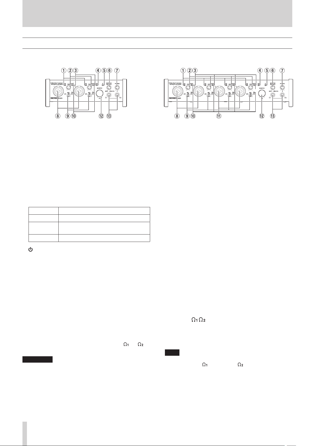
Front panel
SERIES 102i SERIES 208i
1 SIG indicators
These light green when signals (of at least -32 dBFS) are
input.
2 GAIN knobs
Use to adjust the input levels of the input jacks.
3 PEAK indicators
These light red when signals are about to distort (-1 dBFS or
higher).
Adjust these so that the PEAK indicators do not light red.
4 USB indicator
This indicator shows the status of the unit by lighting,
blinking and turning off.
Status Meaning
Lit Good USB connection
Blinking
Unlit Operating in standalone mode
Bad USB connection (disconnected or error
occurred)
5 indicator
This indicator lights when the STANDBY (u) switch is set
to ON.
This indicator blinks if the clock source or OPTICAL input is
irregular (when the clock source is set to OPTICAL).
6 MONITOR BALANCE knob
Use this to adjust the balance between the signals from this
unit’s input jacks and the output signals from the computer.
The volume of signals input through this unit's input jacks
increase the more the MONITOR BALANCE knob is set
to the left (INPUT) and signals output from the computer
increase the more this is set to the right (COMPUTER).
This knob does not affect the recording level of input signals.
Input monitoring without lag is possible by monitoring the
signals from the input jacks (direct monitoring).
7 PHONES knob
Use to adjust the output levels of the PHONES and
jacks.
V
CAUTION
Before connecting headphones, minimize the volume with
the PHONES knob. Failure to do so could result in a sudden
loud noise that could harm hearing, for example.
8 1-2 input jacks
These analog inputs are XLR/TRS combo jacks.
These support high impedance input, including direct guitar
input.
Use the input switches (9) to select balanced line (MIC/LINE)
or unbalanced (INST) input for the TRS jacks.
When directly connecting a guitar, bass or other instrument,
set the input switch (9) to INST.
9 Input switches
Set according to the input source of each input jack.
INST: Select when connecting a guitar, bass or other high-
impedance instrument. This makes it an unbalanced
input for high impedance.
MIC/LINE: Select when connecting a balanced-output mic or
line-level-output device.
+48V: This provides +48V phantom power to the 1-2 XLR
Jacks and 3-4 XLR jacks.
0 +48V indicators
These indicators light when their input switches (9) are set
to +48V.
q 3-4 input connectors (SERIES 208i only)
These analog inputs are XLR/TRS combo jacks.
These support high impedance input, including direct guitar
input.
Use the input switches (9) to select balanced line (MIC/LINE)
or unbalanced (INST) input for the TRS jacks.
When directly connecting a guitar, bass or other instrument,
set the input switch (9) to INST.
w MONITOR knob
Use to adjust the output level of the LINE OUT
(BALANCED) 1-2 (p) jacks on the back of the unit.
e PHONES / jacks
Use this standard stereo jack to connect stereo headphones.
These output the same signals as the LINE OUT
(BALANCED) 1-2 jacks (p) on the back of the unit.
Use an adapter to connect headphones with a mini plug.
NOTE
The same signals are output at the same level (volume) from
both PHONES and PHONES jacks.
TASCAM SERIES 102i / SERIES 208i
4
Page 5
2 - Names and Functions of Parts
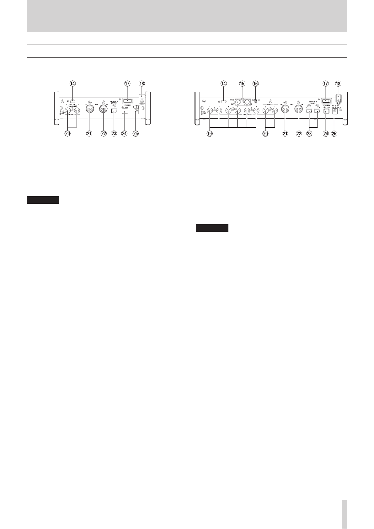
Rear panel
SERIES 102i SERIES 208i
r Kensington Security Slot
t WORD IN/OUT connectors (SERIES 208i only)
These BNC connectors are for the input and output of word
clock signals.
Word clock signals of 44.1, 48, 88.2, 96, 176.4 and 192 kHz can
be input and output.
ATTENTION
If a digital system has multiple word clock masters, serious
problems, including damage to equipment, could occur.
y
75Ω ON/OFF switch (SERIES 208i only)
When this switch is set to ON, the WORD IN connector
terminates to 75 Ω.
u STANDBY switch
Press to turn the unit on and to put it into standby.
i Cord holder
Hook the cord of the included PS-P1220E AC adapter here to
prevent accidental disconnection.
o
LINE OUT (BALANCED) 3-8 jacks (SERIES 208i only)
These standard TRS jacks are analog line outputs.
The nominal output level is +4 dBu.
(Tip: HOT, Ring: COLD, Sleeve: GND)
p LINE OUT (BALANCED) 1-2 jacks
These standard TRS jacks are analog line outputs.
The nominal output level is +4 dBu.
(Tip: HOT, Ring: COLD, Sleeve: GND)
a MIDI OUT connector
This 5-pin DIN is a standard MIDI output connector.
This outputs MIDI signals.
s MIDI IN connector
This 5-pin DIN is a standard MIDI input connector.
Use this to input MIDI signals.
d OPTICAL IN (S/MUX) connector(s)
These input multichannel digital audio in optical format.
44.1, 48, 88.2, 96, 176.4 and 192 kHz sampling frequencies are
supported.
88.2/96 kHz is supported by S/MUX2, and 176.4/192 kHz is
supported by S/MUX4.
f USB port
Use the included USB cable to connect the unit to a
computer.
(Supports USB 2.0.)
ATTENTION
i When connected to a USB 3.0 port, it will function in High
Speed mode equivalent to USB 2.0 (480 Mbps maximum).
i After waking a computer from suspend (sleep) mode, if the
unit does not operate properly, turn it off and turn it on again
or disconnect and reconnect the USB cable.
g DC IN 12V connector
Connect the included AC adapter (PS-P1220E) here.
TASCAM SERIES 102i / SERIES 208i
5
Page 6

3 - Installation
System requirements
Check the TEAC Global Site (http://teac-global.com/) for the
latest information about supported operating systems.
Windows
Supported operating systems
Windows 10 32-bit
Windows 10 64-bit
Windows 8.1 32-bit
Windows 8.1 64-bit
Windows 7 32-bit SP1 or later
Windows 7 64-bit SP1 or later
(Windows 8, Windows Vista and Windows XP are not
supported)
Computer hardware requirements
Windows computer with a USB port that supports at least
USB 2.0 or USB 3.0
CPU/processor speed
2 GHz or faster dual core processor (x86)
Memory
2 GB or more
ATTENTION
Operation of this unit was confirmed using standard
computers that meet the above requirements. This does not
guarantee operation with all computers that meet the above
requirements. Even computers that meet the same system
requirements might have processing capabilities that differ
according to their settings and other operating conditions.
Apple iOS devices
Supported operating systems
Apple device running iOS 10 or later
Supported audio drivers
Windows
USB Audio Class 2.0, ASIO 2.2, WDM (MME), MIDI
Mac
Core Audio, Core MIDI
Apple iOS devices
Core Audio for iPhone
NOTE
Since noise could occur depending on the computer system
used, we recommend selecting “High performance” for
“Plugged in” on the Power Options Control Panel page.
macOS
Supported operating systems
macOS Mojave (10.14 or later)
macOS High Sierra (10.13 or later)
macOS Sierra (10.12 or later)
Computer hardware requirements
Mac with a USB port that supports at least USB 2.0 or USB 3.0
CPU/processor speed
2 GHz or faster dual core processor
Memory
2 GB or more
TASCAM SERIES 102i / SERIES 208i
6
Page 7
3 - Installation
Installing the dedicated software
To use this unit, a dedicated software must be installed on a
computer.
The dedicated software might be updated at any time.
Download the latest software for the operating system you are
using from the TEAC Global Site (http://teac-global.com/).
o On a Windows computer, this will install the Windows driver
and Settings Panel application.
o Installing the dedicated software on a Mac will install only
the Mac Settings Panel application. The standard OS driver
will be used.
o With an iOS device, the standard OS driver will be used, so
there is no need to install any.
ATTENTION
Before starting to install software, quit other applications.
Installing the Windows dedicated software
Follow the procedures below to install the Windows dedicated
software.
ATTENTION
i Complete installation of the Windows dedicated software on
the computer before connecting the unit to it with the USB
cable.
i If you connected the unit to the computer using the USB
cable before installing the Windows dedicated software
and the “Found New Hardware Wizard” launched, close the
Wizard and disconnect the USB cable.
Windows dedicated software installation
procedures
1. Download the latest Windows dedicated software for the
operating system you are using from the TEAC Global Site
(http://teac-global.com/) and save it on the computer to
be used with the unit.
2. Uncompress the saved software (zip file) on the computer
desktop or another location.
3. Double-click the “TASCAM_SERIES_102i_208i_Installer_x.
xx.exe” (x.xx is the version number) file in the folder that
appears after uncompression to automatically launch the
installation software.
ATTENTION
If you open a zip file without decompressing it and
doubleclick the “TASCAM_SERIES_102i_208i_Installer_x.
xx.exe” file in the folder that opens, installation will not start.
Right-click the zip file and select “Extract All”, for example, to
decompress it and then try again.
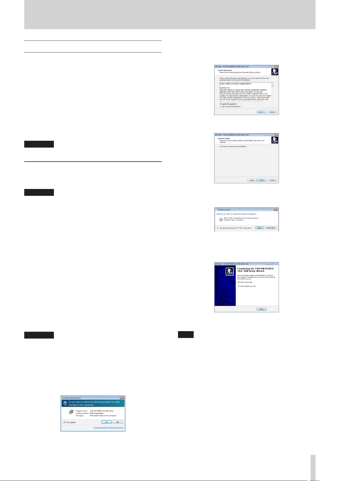
4. Depending on the computer set up, a “Security Warning” or
“User Account Control” screens might appear. If this occurs,
click the “Yes ” button.
5. Read the contents of the License Agreement, and select “I
accept the agreement” if you agree to the terms.
Then, click the “Next” button.
6. Next, click the “Install” button.
7. When the Windows security screen appears, click the
“Install” button to start installation.
8. The following screen appears when installation has
completed.
Click the “Finish” button.
The installer will quit and the Windows Settings Panel will
launch.
NOTE
The first time you connect the unit by USB to the computer
after installing the software, installation of the device driver
will be executed. Some time might be necessary before
the unit is recognized because Windows Update will be
automatically searched at this time. If the unit is still not
recognized after a while, open the software installation
screen from the notification area at the bottom right of the
computer display, and click “Skip obtaining driver software
from Windows Update” to stop the search.
TASCAM SERIES 102i / SERIES 208i
7
Page 8
3 - Installation
Installing the Mac dedicated software
NOTE
i Install the Mac dedicated software on the computer before
connecting the unit to it with the USB cable.
i Depending on the Gatekeeper setting, a warning message
might appear during installation. Please see “Working with
Gatekeeper” on page 8 for information about Gatekeeper.
Mac dedicated software installation
procedures
1. Download the latest Mac dedicated software for the
operating system you are using from the TEAC Global Site
(http://teac-global.com/) and save it on the computer to
be used with the unit.
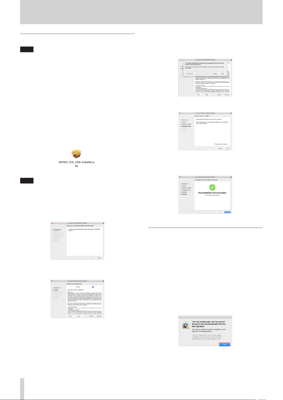
2. Double-click “TASCAM_SERIES_102i_208i_Installer_x.xx.dmg”,
which is the saved disk image file for the Mac dedicated
software, and double-click “SERIES_102i_208i_Installer.pkg”
inside the folder that opens.
5. Click the “Read License” button and check the contents
of the Software License Agreement. If you agree to the
contents of the license, click “Agree”.
Then, click the “Next” button.
6. Next, click the “Install” button to start installation.
7. The following screen appears when installation has
completed.
Click the “Close” button.
NOTE
Depending on the computer’s settings, the downloaded zip
file might not have been uncompressed automatically. In this
case, uncompress the zip file first and then double-click the
disk image file.
3. When the installer starts, click the “Continue” button.
4. Next, select the desired language and click the “Continue”
button.
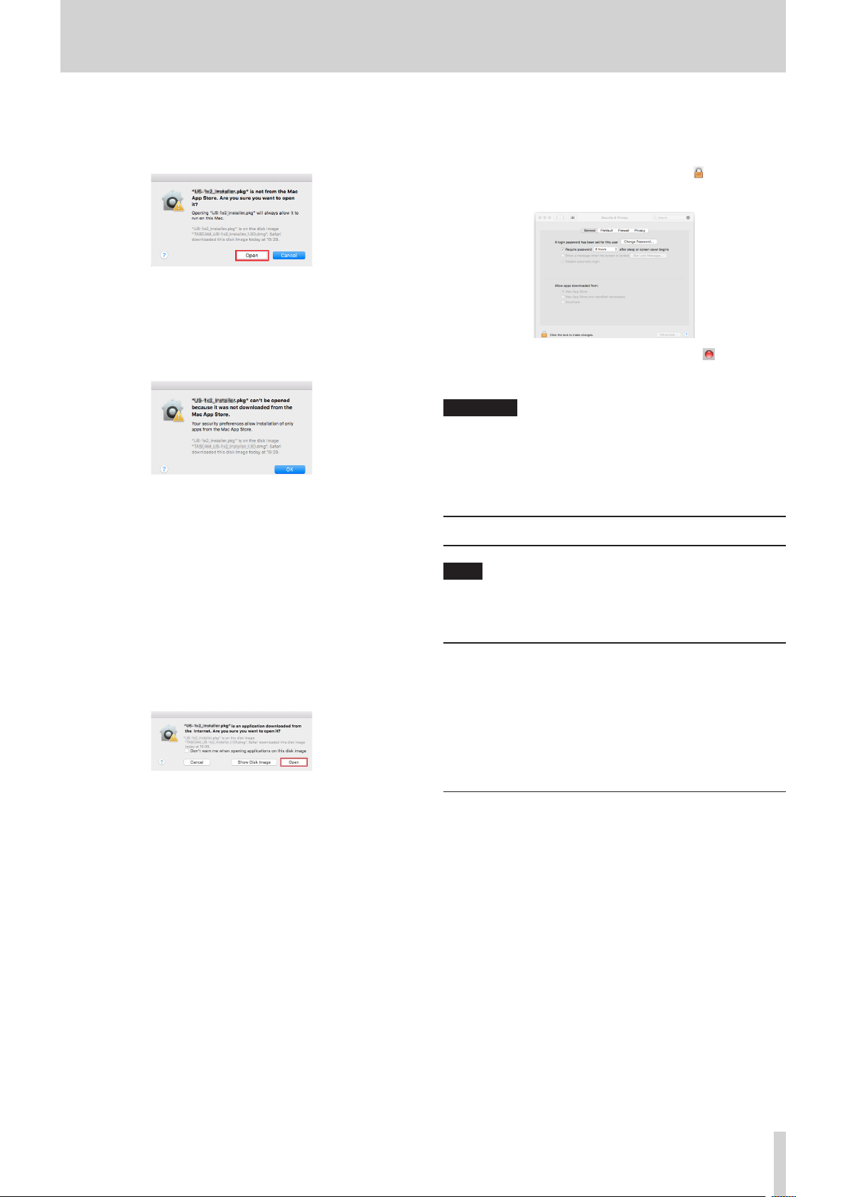
Working with Gatekeeper
When using macOS, depending on the Gatekeeper security
function setting, a warning message might appear during
installation.
The solution depends on the warning message shown.
See the following explanations for details.
When the Gatekeeper setting is “Allow
applications downloaded from: the Mac App
Store”
The following security warning might be shown:
““SERIES_102i_208i_Installer.pkg” can’t be opened because
it was not downloaded from the Mac App Store.” In this case,
click the “OK” button to close the message.
TASCAM SERIES 102i / SERIES 208i
8
In this case, click the OK button to close the message. Then,
control-click (or right-click) the file and click “Open”.
Page 9
3 - Installation
When the ““SERIES_102i_208i_Installer.pkg” can’t be opened
because it was not downloaded from the Mac App Store. Are
you sure you want to open it?” security warning message
appears, click the “Open” button.
This warning message might also appear when the
Gatekeeper setting is something other than “Allow
applications downloaded from: the Mac App Store.”
The file still might not open and “SERIES_102i_208i_Installer.
pkg” can’t be opened because it was not downloaded from
the Mac App Store.” might appear again.
In this case, copy the file from the folder where it is to the
desktop or another folder, and then open it. Alternatively,
change the Gatekeeper settings to “Allow applications
downloaded from: the Mac App Store and identified
developers” and try opening it again.
When the Gatekeeper setting is not “Allow
applications downloaded from: the Mac App
Store”
““TASCAM_SERIES_102i_208i_Installer_x.xx.dmg.” is an
application downloaded from the Internet. Are you sure you
want to open it?” might appear as a security warning message.
In this case, click the “Open” button.
Changing the Gatekeeper setting
The Gatekeeper setting can be changed using the “Allow
applications downloaded from:” item on the “General” page
of the “Security & Privacy” pane of the System Preferences.
To change this, you must click the lock icon ( ) at the bottom
left and enter a password to unlock the settings.
This setting will lock again when you click the button or
type command-Q to close the System Preferences or when
you click “Show All” to close the open pane.
ATTENTION
Changing the Gatekeeper settings could result in security
risks.
If you changed the Gatekeeper setting to decrease security
(use one of the lower settings), set it back to the original
setting after updating the driver and/or firmware.
Uninstalling the dedicated software
NOTE
Normally, there is no need to uninstall the dedicated
software. Follow these procedures if a problem occurs or you
no longer intend to use the unit with the computer.
Uninstalling the Windows dedicated software
1. Open the “Uninstall or change a program” screen using the
procedures for the operating system being used (Windows
10/Windows 8.1/Windows 7).
2. Select “TASCAM SERIES 102i_208i version x.xx” from the list,
and double-click it.
3. Then, follow the instructions that appear on the screen.
Uninstalling the Mac dedicated software
Delete “SERIES 102i_208i” from the Application folder to
complete uninstallation.
TASCAM SERIES 102i / SERIES 208i
9
Page 10
4 - Preparation
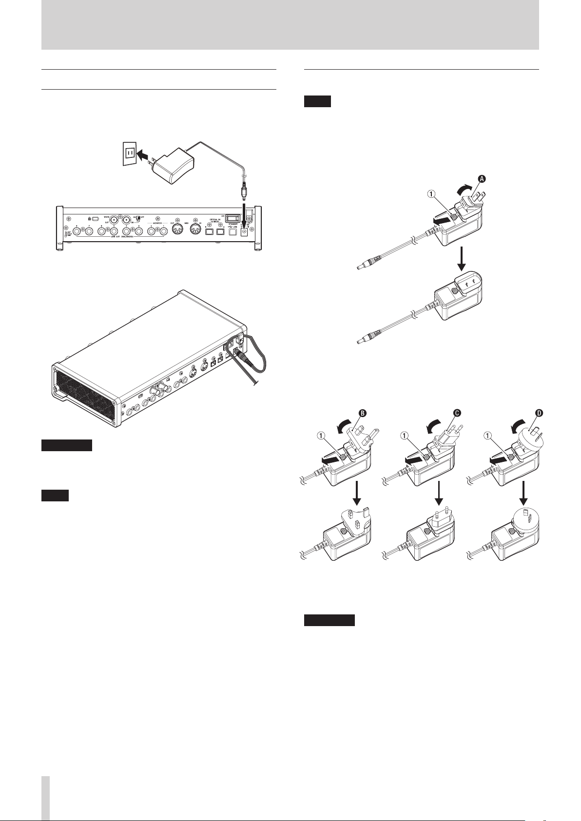
Connecting the power
Use the included AC adapter (PS-P1220E) to connect a power
supply to the unit as shown below.
Power outlet
PS-P1220E (included)
DC plug
In order to prevent the cord from becoming disconnected
during use, wrap it around the cord holder when connecting it.
Changing the outlet plug
NOTE
When purchased new, the included PS-P1220E AC adapter
for the unit has an outlet plug (A) already attached. There
should be no need to change the plug.
1. Move the knob (1) on the PS-P1220E AC adapter in the
direction of the arrow and remove the plug (A).
2. Select the plug that matches the AC outlet from the 3 other
types included (B, C or D).
3. Move the knob (1) in the direction of the arrow again, and
attach the plug to the AC adapter.
ATTENTION
Always use the AC adapter (PS-P1220E) that was shipped
with the unit. Using a different AC adapter could cause
malfunction, overheating, fire or other problems.
NOTE
The AC adapter for the unit includes 4 types of outlet plugs.
Attach the type of plug that matches the power outlet that
you are using. (see “Changing the outlet plug” on page 10)
This completes changing the outlet plug.
After changing the outlet plug, confirm that it is not loose or
crooked and that everything is normal before plugging it into an
outlet.
ATTENTION
Do not use the adapter if there is anything abnormal about
the plug after changing it. Use when the plug is abnormal
could cause fire or electric shock. Contact the retailer where
you purchased the unit or a TEAC service center (on the back
cover) to request repair.
TASCAM SERIES 102i / SERIES 208i
10
Page 11
4 - Preparation
Connecting other equipment
This is an example of SERIES 208i connections.
Precautions before making connections
o Carefully read the operation manuals of the devices to be
connected and then connect them correctly.
o Before making connections, turn this unit and all equipment
to be connected off (standby).
o If possible, install all connected devices so that they are
powered from the same AC power supply line. When using
a power strip or similar device, be sure to use one that has a
thick cable with high current capacity in order to minimize
voltage fluctuations in the AC power supply.
Guitar
Bass
Connecting with a computer
Use the included USB cable to connect the unit to a computer
USB port compatible with 2.0, 3.0 or higher USB specifications.
When the USB connection is working, the USB indicator on the
front of the unit lights.
ATTENTION
If you connect this unit to a computer via a USB hub, for
example, audio signal dropouts, clicking noises and other
interference could occur due to the influence of other USB
devices connected to that hub. For this reason, we strongly
recommend connecting this unit to a separate USB port.
Connecting USB keyboards and mice, however, to the same
bus should not be a problem.
Connecting with iOS devices
You will need a Lightning to USB Camera Adapter and the USB
cable included with this unit to connect an iOS device.
NOTE
i When connected, this unit will not provide power to the iOS
device.
i iOS does not support 176.4/192 kHz sampling frequencies.
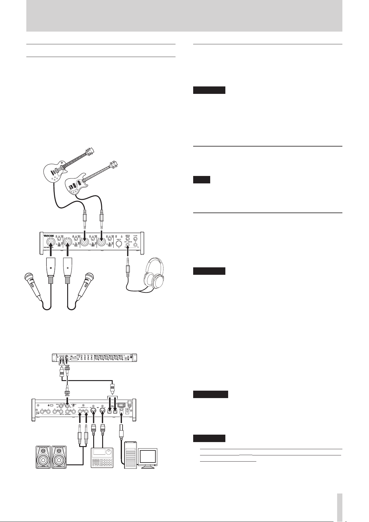
Audio connections
Analog audio signals input into this device from mics, guitars,
keyboards and other audio equipment can be converted into
digital signals and transmitted to the computer via USB. In
addition, by connecting speakers (through an amplifier if not
powered) or headphones to this unit, you can monitor audio
signals that are input to this unit and output from the computer.
Headphones
Mic
Mic preamp with S/MUX
(When using the word clock output of a TASCAM
SERIES 8p Dyna as the clock master for this unit)
ComputerDrum machinePowered speakers
Examples of connections to a SERIES 208i
ATTENTION
Before connecting audio equipment, set the GAIN,
MONITOR and PHONES knobs to their lowest values.
Failure to do so could cause sudden loud noises from
monitoring equipment, and this could damage the
equipment or harm hearing.
Connecting microphones
Dynamic mics
Connect these to the 1-2 (or 3-4 on SERIES 208i) input
jacks on the front of the unit.
Condenser mics
When using a condenser mic that requires phantom
power, connect it to a 1-2 (or 3-4 on SERIES 208i) input
jack, and then set the input switch to +48V.
When the input switch is set to +48V, the +48V indicator
on the front of the unit lights.
V
CAUTION
Set the MONITOR and PHONES knobs to their minimum
values before changing the input switch setting. Failure
to do so could cause sudden loud noises from monitoring
equipment, and this could damage equipment or harm
hearing.
ATTENTION
i Input switches can be set for each channel separately. Do not
set the switch to +48V when connecting a mic that does not
require phantom power.
i Do not connect or disconnect mics when the switch is set to
+48V. Doing so could cause a loud noise and might damage
this unit and connected equipment.
i Set the switch to +48V only when using a condenser
TASCAM SERIES 102i / SERIES 208i
11
Page 12

4 - Preparation
microphone that requires phantom power. Setting the
switch to +48V when a dynamic mic or other device that
does not require it is connected could damage this unit and
connected equipment.
i Supplying phantom power to some ribbon mics could break
them. If you are unsure, do not supply phantom power to a
ribbon mic.
Connecting guitars
When connecting a guitar or bass guitar directly to this unit, use
a 1-2 (or 3-4 on SERIES 208i) jack on the front of the unit and set
its input switch to INST.
Connecting electronic devices and other
audio equipment
When connecting an electronic instrument or other audio
equipment directly to this unit, use a 1-2 (or 3-4 on SERIES 208i)
jack on the front of the unit and set its input switch to MIC/
LINE.
Connecting analog record players
The output of an analog record player cannot be connected
directly to this unit. To connect an analog record player to this
unit, a phono amp and equalizer (or an audio amplifier that has
phono input jacks) must be connected between them.
MIDI connections
Connect sound modules, keyboards, synthesizers, drum
machines and other MIDI devices to the unit in the following
manner.
o If you want to monitor sound from a MIDI device, connect its
audio outputs to the 1-2 (or 3-4 on SERIES 208i) jacks on the
front of the unit or use an external mixer.
o You can also use the MIDI IN and MIDI OUT connectors on the
back of the unit to send and receive MIDI timecode (MTC). By
doing this, you can use an application that supports MTC to
synchronize a multitrack recorder (MTR) and MIDI devices.
Connecting monitor speakers
Connect monitor speakers (powered speakers or an amplifier
and speaker system) to the LINE OUT (MONITOR) 1-2 jacks
on the back of the unit.
Use the MONITOR knob on the front of the unit to adjust the
speaker volume.
Connecting headphones
Connect headphones to the PHONES and PHONES
jacks (standard stereo) on the front of the unit.
V
CAUTION
Before connecting headphones, minimize the volume with
the PHONES knob. Failure to do so could result in a sudden
loud noise that could harm hearing, for example.
NOTE
The same signals are output at the same level (volume) from
both PHONES and PHONES jacks.
TASCAM SERIES 102i / SERIES 208i
12
Page 13

5 - Using the Settings Panel
Opening the Settings Panel
You can use the Settings Panel to make settings for the various
functions of this unit.
Open the Settings Panel in the following manner.
NOTE
The Settings Panel cannot be used with an iPad or other iOS
device.
Windows
o From the Start menu select “SERIES 102i_208i” under
“TASCAM”.
Mac
o On the Launchpad, click SERIES 102i_208i.
o Using the Finder, open the Applications folder and double-
click SERIES 102i_208i to open the Settings Panel.
o In the Audio Devices window of the Audio MIDI Setup
application, right-click (control-click) “SERIES 102i” or “SERIES
208i”. Alternatively, click the button and click “Configure
device…” from the menu that appears to open the Settings
Panel.
MIXER page
SERIES 102i Settings Panel MIXER page in Windows
Settings Panel overview
The Settings Panel has three pages.
Click a tab at the top of the Settings Panel to open that page.
o MIXER: Make built-in mixer and effect settings.
o INFORMATION: This shows the current status of the driver
and information about connections. You can
also make various settings.
o ROUTING: Make output settings (and Monitor Control
settings for the SERIES 208i).
ATTENTION
When you open the Settings Panel, the state will be the
same as the last time closed. However, the setting values
on each page (MIXER, INFORMATION and ROUTING) will be
the same as when last closed, but will not have been saved
in a scene memory. To save settings in a scene memory, use
the Scene Memory menu in the menu bar. (see “Using the
SceneMemory menu” on page 24)
Moreover, to use settings in standalone mode, they must be
saved to the unit. To save settings to the unit, To save settings
to the unit, select “Save into the unit” under SceneMemory in
the menu bar. (see “Saving Settings Panel settings to the unit”
on page 26)
SERIES 208i Settings Panel MIXER page in Windows
1 EQUALIZER
This unit has a 4-band equalizer (with HIGH, HIGH MID, LOW
MID and LOW bands).
Use the equalizer to increase or decrease the levels of
specific frequency ranges. This can be used, for example,
to enhance the sound of individual instruments, to adjust
the balance of a wide frequency range and to cut specific
unwanted frequencies. (see “This can be selected when set to
BROADCAST, but it will always function as MONO.” on page
14)
Activate the Select button of a channel to make equalizer
settings for it.
Equalizer settings are shown here for the channel activated
using its Select button.
TASCAM SERIES 102i / SERIES 208i
13
Page 14

5 - Using the Settings Panel
2 COMPRESSOR area
When the input volume exceeds the THRESHOLD level,
the input volume is compressed, reducing output volume
variation.
For example, by reducing the levels of sounds that are high
level, lower level sounds become relatively louder, creating
a more even volume level throughout and a more sustained
sound. (see “COMPRESSOR display area overview” on page
15)
Activate the Select button of a channel to make compressor
settings for it.
Compressor settings are shown here for the channel
activated using its Select button.
NOTE
i If the input is a stereo signal (stereo-linked channel or
master), compression will start and be applied to both
channels when either the left or right input channel exceeds
the threshold level.
i When the compressor is off, the compressor curve will appear
but the meters will not be active.
3 REVERB area
This effect adds reverberations to the original sound. Multiple
sounds are delayed at various times with damping over time
that is as natural as possible to produce reverberations like
those of a hall, live-music club or studio, for example. (see
“REVERB display area overview” on page 15)
4 Channel Mixer
Check and make settings for each channel. (see “Channel
Mixer details” on page 16)
NOTE
All channels are available when a SERIES 208i is connected.
When a SERIES 102i is connected, the INPUT 3, INPUT 4
and OPT B1 – B8 channels cannot be used and will appear
dimmed.
5 Output adjustment section
Make REVERB, AUX MASTER and STEREO MASTER settings
here. (see “Output adjustment section” on page 18)
This can be selected when set to
BROADCAST, but it will always function as
MONO.
Use this to increase or decrease the levels of specific frequency
ranges.
This can be used, for example, to enhance the sound of
individual instruments, to adjust the balance of a wide
frequency range and to cut specific unwanted frequencies.
The equalizer has a high-shelf HIGH band, a low-shelf LOW band
and peaking (bell-shaped) HIGH MID and LOW MID bands.
1 EQ graph
This shows the frequency response with the current equalizer
settings.
The graph is shown even when the equalizer is off.
2 GAIN (HIGH/HIGH MID/LOW MID/LOW) knobs
Set the amount the levels are increased or decreased for the
HIGH, HIGH MID, LOW MID and LOW bands.
Range: ±12 dB (default: 0 dB)
3 FREQ (HIGH/HIGH MID/LOW MID/LOW) knobs
Set the cutoff frequencies of the HIGH, HIGH MID, LOW MID
and LOW bands.
Ranges
HIGH: 1.7 kHz - 18.0 kHz (default: 5 kHz)
HIGH MID: 32 Hz - 18.0 kHz (default: 1.2 kHz)
LOW MID: 32 Hz - 18.0 kHz (default: 300 Hz)
LOW: 32 Hz - 1.6 kHz (default: 80 Hz)
4 Q (HIGH MID/LOW MID) knobs
Set the acutenesses of the peaks of the HIGH MID and LOW
MID bands.
The higher the value the more acute it becomes, making it
affect a narrower frequency band. The lower the value, the
less acute it becomes, making it affect a broader frequency
band.
Ranges
HIGH MID: 0.25 - 16.00 (default: 1.00)
LOW MID: 0.25 - 16.00 (default: 1.00)
5 LCF button
Click the LCF button to enable a low cut filter that cuts noise
and other sounds at low frequencies. The LC F button lights
when enabled. (Default: off)
TASCAM SERIES 102i / SERIES 208i
14
Page 15

5 - Using the Settings Panel
COMPRESSOR display area overview
When the input volume exceeds the THRESHOLD level, the input
volume is compressed, reducing output volume variation.
For example, by reducing the levels of loud sounds, lower level
sounds become relatively louder, creating a more even volume
level throughout and a more sustained sound.
1 Compressor status display
Three meters show the level of the signal input to the
compressor (INPUT), the level of the signal output from the
compressor (OUTPUT) and the gain reduction caused by the
compressor (GR).
2 THRESHOLD knob
Sets the threshold level that will cause the compressor to
start.
Range: -32 dB - 0 dB (default: 0 dB)
3 RATIO knob
Sets the compression ratio for the input volume.
Turning it right raises the compression ratio, increasing the
amount of compression.
Range: 1.0:1 - inf:1 (default: 1.0:1)
4 GAIN knobs
Sets the gain of the output signal.
When the volume is compressed, the output level becomes
lower than the input level. Use the GAIN knob to increase the
output level so that it is close to the input level.
Range: 0 dB - 20 dB (default: 0 dB)
5 AT TACK knob
Sets the amount of time until the compression reaches the
compression RATIO setting after the input volume exceeds
the threshold.
Range: 2 ms - 200 ms (default: 2 ms)
6 RELEASE knob
Sets the amount of time until the compression stops and
the sound returns to its uncompressed level after the input
sound goes below the threshold level.
Range: 10 ms - 1000 ms (default: 10 ms)
REVERB display area overview
This effect adds reverberations to the original sound. Multiple
sounds are delayed at various times with damping over time
that is as natural as possible to produce reverberations like
those of a hall, live-music club or studio, for example.
1 Reverb status display
This shows the setting status of the PRE DELAY and REVERB
TIME knobs.
2 Reverb type switch
Use to select the type of reverb.
Depending on the type, the density and level of the reverb
sound changes.
Options: HALL (default), ROOM, LIVE, STUDIO, PL ATE
3 PRE DELAY knob
Set the amount of delay until the first reverberations.
The larger the value, the larger the reverberations make the
room sound.
Range: 0 ms - 250 ms (default: 90 ms)
4 REVERB TIME knob
Set the amount of time that the reverberations continue.
The larger the value, the longer they continue.
Range: 0.1 s - 10 s (default: 2.7 s)
5 DIFFUSION knob
Sets the breadth of the reverberations.
Range: 0 - 100 (default: 20)
NOTE
In the menu bar, open the View menu and click Initialize
Reverb to reset the settings shown in the REVERB section to
their default values. (see “Resetting the reverb settings” on
page 23)
NOTE
i If the input is a stereo signal (stereo-linked channel or
master), compression will start and be applied to both
channels when either the left or right input channel exceeds
the threshold level.
i When the compressor is off, the compressor curve will appear
but the meters will not be active.
TASCAM SERIES 102i / SERIES 208i
15
Page 16

5 - Using the Settings Panel
Channel Mixer details
Settings Panel MIXER page channels 1–2
1 Select button
The equalizer and compressor settings for the selected
channel are shown in the EQUALIZER and COMPRESSOR
sections.
Off (default): Select button unlit
ON: Select button lit
To select a different channel, click that channel's button. The
previously selected channel button will become unlit, and
the newly selected channel button will light.
2 φ button
Use these to change the phases of the signals on each
channel.
If the phase becomes reversed due to the wiring of a mic or
other cause, turn the φ button on (lit) to reverse the phase of
the channel. (Default: off)
3 THRU button
Click a THRU button to light it and send the input signal
for that channel directly to the computer without passing
through the input signal mixer.
Since the signal does not pass through the mixer, phase,
equalizer and compressor settings will have no effect.
4 EQ button
Use these to turn the equalizer on/off for each channel.
Click the EQ button to activate the equalizer. The EQ button
will light and the equalizer settings shown in the EQUALIZER
section will be applied.
5 COMP button
Use these to turn the compressor on/off for each channel.
Click the COMP button to activate the compressor. The COMP
button will light and the compressor settings shown in the
COMPRESSOR section will be applied.
6 PRE/POST buttons
Set whether the signal sent to the AUX bus is pre-fader or
post-fader.
The selected button lights.
Status Meaning
PRE button unlit
POST button unlit
(default)
PRE button lit
POST button lit
The signal is not sent to the AUX
bus.
The signal is sent to the AUX bus
before adjustment by the channel
fader.
The AUX level will not be affected by
the channel fader.
The signal is sent to the AUX bus
after adjustment by the channel
fader.
The AUX level will be affected by the
channel fader.
7 AUX 1-4 knobs and indicators
Use to adjust the levels of the signals sent to the AUX bus
(AUX levels).
Range: -inf. to 6 dB (default: -inf.)
Drag an AUX knob up or down to adjust that AUX level.
While dragging, the value being adjusted is shown below
and to the right of the AUX knob.
The indicator lights blue at levels of 0 dB or less and yellow at
levels from 0 dB to 6 dB.
8 SOLO button
When SOLO buttons are turned on, other channels will
automatically be muted (in place solo monitoring).
The MUTE buttons of muted channels will light. (Default: off )
Multiple channels can be soloed at the same time.
NOTE
i When all the SOLO buttons are off, clicking the SOLO button
of one channel will solo it, automatically muting the other
channels and lighting their MUTE buttons.
i If every SOLO button is turned off, channels that had been
automatically muted will become unmuted. Channels that
had been individually muted before any channel was soloed
will remain muted.
i The STEREO MASTER channel MUTE button will not turn on
automatically because of soloing.
9 MUTE button
Click a MUTE button to mute that channel. The button lights
when the channel is muted. (Default: off )
NOTE
In addition to turning the MUTE button on and off, channels
will be automatically muted and unmuted when SOLO
buttons are used.
TASCAM SERIES 102i / SERIES 208i
16
Page 17

5 - Using the Settings Panel
0 Pan slider
Use to adjust the stereo positions of the signals input to each
channel.
Drag the pan slider left or right to adjust the stereo position.
While dragging, the adjusted position is shown above the
channel level meter (w).
The value is L20 when set all the way to the left, R20 when set
all the way to the right and C when centered.
Setting range: L20 - L1, C (default), R1 - R20
The pan slider appears blue when centered (C) and yellow at
all other positions.
NOTE
i When the pan slider is centered (C), signals reduced by 3 dB
are sent to both the stereo left and right buses.
i Double-click the pan slider to return it to the center (C)
position.
i When the pan slider is at the left end (L20), the signal is sent
only to the left bus of the stereo bus. It is not sent to the right
bus.
i When the pan slider is at the right end (R20), the signal is
sent only to the right bus of the stereo bus. It is not sent to
the left bus.
q Channel fader
Use these to adjust the levels of the signals sent from each
channel to the stereo bus.
Range: -infinity to 6.0 dB (default: 0.0 dB)
Drag a channel fader up or down to adjust the channel level.
The gain value of the channel fader is shown in the fader
level display area (e).
t Channel note
You can input up to six alphanumeric characters.
Character input
i Click one of these areas. The cursor will blink when
ready for input. When the unit is ready, use a computer
keyboard to input characters. When done inputting, press
the computer Enter key to confirm.
i When done inputting characters, you must press the
computer Enter key to confirm. If you do not press the
Enter key before switching from the MIXER page to a
different page, the input characters will continue to be
shown but will not be saved.
NOTE
Shift-click the fader to set it to 0 dB.
w Channel level meter
These meter show the signal levels of each channel.
The channel level meter appear green at levels of -12 dB or
less, yellow at levels from -12 dB to -6 dB and red at levels
above -6 dB.
Each level meter has an overload indicator at its top.
NOTE
The channel meter show the level before being adjusted by
the fader. Level meter are not affected by fader adjustment or
even their channel being muted.
e Fader level display area
These show the level of the channel fader above them as
decibel value.
r LINK button
Click a LINK button to unite odd and even channel as a single
stereo channel. When linked, this button lights for those
channel. (Default: off )
When a pair is stereo linked, the buttons and knobs of the
channels are combined. The channel level meters are also
shown is a stereo pair.
See “LINK button overview” on page 19 for details.
TASCAM SERIES 102i / SERIES 208i
17
Page 18

5 - Using the Settings Panel
Output adjustment section
1 REVERB button
Click the REVERB button to apply reverb.
(Default: on)
When the reverb is on, the REVERB button lights.
NOTE
The reverb cannot be turned on if the sampling frequency is
176.4/192 kHz.
2 RETURN knob and indicator
Use to adjust the return level, which is the signal from the
reverb effect returned to the stereo bus.
Range: -inf. to 6 dB (default: -inf.)
Drag the RETURN knob up or down to adjust the return level.
While dragging, the value being adjusted is shown below
and to the right of the RETURN knob.
The indicator lights blue at levels of 0 dB or less and yellow at
levels from 0 dB to 6 dB.
3 AUX MASTER 1/REVERB knob and indicator
Use this to adjust the send master level of the signal sent to
the AUX 1 bus and reverb effect.
Range: -inf. to 6 dB (default: 0 dB)
Drag the 1/REVERB knob up or down to adjust the send level.
While dragging, the value being adjusted is shown below
and to the right of the 1/REVERB knob.
The indicator lights blue at levels of 0 dB or less and yellow at
levels from 0 dB to 6 dB.
4 AUX MASTER 2-4 knobs and indicators
Use these to adjust the send master levels of the signals sent
to the AUX 2-4 buses.
Range: -inf. to 6 dB (default: 0 dB)
Drag the 2-4 knobs up or down to adjust the send levels.
While dragging, the value being adjusted is shown below
and to the right of the 2-4 knob.
The indicator lights blue at levels of 0 dB or less and yellow at
levels from 0 dB to 6 dB.
5 MUTE button
This mutes the STEREO MASTER output. (Default: off )
6 STEREO MASTER fader
Use this to adjust the level of the output signal.
Range: -infinity to 6.0 dB (default: 0.0 dB)
Drag the STEREO MASTER fader up or down to adjust the
master level.
The value being adjusted is shown in the STEREO MASTER
fader level display area (8).
7 STEREO MASTER level meters
The master levels are shown by this stereo level meter.
The STEREO MASTER level meters appear green at levels of
-12 dB or less, yellow at levels from -12 dB to -6 dB and red at
levels above -6 dB.
Each level meter has an overload indicator at its top.
NOTE
The STEREO MASTER level meter shows the levels after
being adjusted by the fader (post fader). The level meters are
affected by fader adjustments and channels being muted.
8 STEREO MASTER fader level display area
This shows the level of the STEREO MASTER fader as a decibel
value.
TASCAM SERIES 102i / SERIES 208i
18
Page 19

5 - Using the Settings Panel
LINK button overview
When a LINK button on the MIXER page is turned on/off, the settings differ according to whether the stereo link is on or off.
The details of the settings are as follows.
When a LINK button is turned on
Button/knob Setting status
On if a Select button was on (lit)
Select buttons
φ (phase) buttons
THRU buttons
EQ buttons
COMP buttons
PRE/POST buttons
AUX knobs (1–4)
SOLO buttons
MUTE buttons
Pan sliders
Channel faders
Channel level meters
Fader level display areas
for either channel.
Off if the Select buttons were off
(unlit) for both channels.
Settings are not combined.
Both channels retain their
previous settings.
The setting of the odd channel is
used for both.
The setting of the odd channel is
used for both.
The setting of the odd channel is
used for both.
The setting of the odd channel is
used for both.
The setting of the odd channel is
used for both.
The setting of the odd channel is
used for both.
The setting of the odd channel is
used for both.
Settings are not combined.
Odd and even channels can each
be set independently.
The setting of the odd channel is
used for both.
The channel level meters are
shown as a stereo pair.
The setting of the odd channel is
shown.
When a LINK button is turned off
Button/knob Setting status
When on (lit), the odd channel
will be turned on and the even
Select buttons
φ (phase) buttons
THRU buttons
EQ buttons
COMP buttons
PRE/POST buttons
AUX knobs (1-4)
SOLO buttons
MUTE buttons
Pan sliders
Channel faders
Channel level meters
Fader level display areas
channel will be turned off.
When off (unlit), both channels
will be turned off.
Settings do not change. Both
channels retain their previous
settings.
Both channels use the settings
they shared when stereo-linked.
Both channels use the settings
they shared when stereo-linked.
Both channels use the settings
they shared when stereo-linked.
Both channels use the settings
they shared when stereo-linked.
Both channels use the settings
they shared when stereo-linked.
Both channels use the settings
they shared when stereo-linked.
Both channels use the settings
they shared when stereo-linked.
Both channels use the settings
they shared when stereo-linked.
Both channels use the settings
they shared when stereo-linked.
The channel level meters switch
to showing mono signals.
Both channels use the settings
they shared when stereo-linked.
NOTE
When a LINK button is on (lit), the select button names
change to a name used when the stereo link is active.
Examples
When the INPUT 1 and INPUT 2 buttons are linked, the
name of the button changes to INPUT 1-2.
TASCAM SERIES 102i / SERIES 208i
19
Page 20

5 - Using the Settings Panel
INFORMATION page
1 Status display area
This shows the current status of the unit.
Item displayed Meaning
Software Version This is the software version.
Firmware version
Device
Clock Source
Sample Rate
Clock Source Status
OPTICAL A Input Status
OPTICAL B Input Status
(SERIES 208i only)
* Note about the sample rate of this unit
i Win: Set the same sample rate for both the Playback and
Recording tabs of the Sound Properties in Control
Panel screen.
i Mac: Set the sample rate in the Audio Devices window of
Audio MIDI Setup.
This is the firmware version used
by the connected unit.
This is the name of the connected
unit. (No Device is shown when no
device is connected.)
This shows the name of the
currently selected clock source.
This shows the current sampling
frequency.
This shows the sampling clock
status.
Good: There are no problems.
Unlocked (or No Signal):
There is no valid signal or it is
disconnected.
Phase Error:
This unit and the device that
is optically connected are not
synchronized.
Sample Rate Mismatch:
This unit and the device that
is optically connected have
different sample rates.
This shows the OPTICAL input
status.
Good: There are no problems.
Unlocked (or No Signal):
There is no valid signal or it is
disconnected.
Phase Error:
This unit and the device that
is optically connected are not
synchronized.
Sample Rate Mismatch:
This unit and the device that
is optically connected have
different sample rates.
NOTE
i When the unit and the computer are not connected, “No
Device” is shown for the “Firmware Version” and “Device”
items.
i When the 2 Sample Clock Source item is set to “Internal”, the
Clock Source Status item will appear dimmed as “----------”.
2 Sample Clock Source
Use this to set the sampling clock source.
Option Meaning
INTERNAL
OPTICAL A
OPTICAL B
(SERIES 208i only)
WORD
(SERIES 208i only)
NOTE
i When set to OPTICAL A, OPTICAL B or WORD, if no
signal is input through the corresponding connector or
synchronization becomes impossible, the status will appear
in the Clock Source Status item and this unit's STANDBY
indicator will blink.
i When connecting multiple digital devices to the SERIES 208i,
synchronize them to a system word clock and input word
clock supplied by the master clock device to the SERIES 208i.
i After changing the clock source, proper continuation of
playback/recording might not be possible, so you should
restart the playback/recording software that you are using.
The unit's built-in clock is always
used.
The clock signal input through the
OPTICAL IN (S/MUX) connector
is used.
If the connected device is a
TASCAM device and 3 Rate
setting is “Auto - TASCAM Device”,
the input clock signal will be
automatically identified and set.
The clock signal input through the
WORD IN connector is used.
3 Rate items
Use these to set the connected OPTICAL (S/MUX) sample
rates.
If the connected device is also a TASCAM product, select
“Auto - TASCAM Device” to set this automatically.
Options:
Auto - TASCAM Device, Manual - 44.1kHz/48kHz,
Manual - 88.2kHz/96kHz, Manual - 176.4kHz/192kHz
4 Buffer Size (Windows only)
The Windows driver for the unit stores the audio signals
transferred to and from the computer temporarily in a buffer.
This buffer size can be adjusted.
Smaller buffer sizes result in less audio signal delay (latency),
but require high-speed processing by the computer.
If the processing cannot keep up, for example, due to other
system operations, clicking and popping noises might occur
and the audio signal might even drop out.
Increasing the buffer size will stabilize operation and
suppress negative effects on audio signals, but the delay in
audio signals sent to the computer will increase.
You can use the slider on the panel to adjust the buffer size,
according to the use conditions.
Use the slider to select fixed values that increase from left to
right.
Options: 4 Samples, 8 Samples, 16 Samples, 24 Samples,
32 Samples, 64 Samples, 128 Samples,
256 Samples, 512 Samples, 1024 Samples,
2048 Samples
TASCAM SERIES 102i / SERIES 208i
20
Page 21

ROUTING page
SERIES 102i Settings Panel ROUTING screen
SERIES 208i Settings Panel ROUTING screen
1 Status display area
This shows the connections between the signals selected
in the output signal selection area (2) and the output
connectors.
2 Output signal selection area
Click the output signal selection area to open a pull-down
menu and select the signal you want to output.
SERIES 102i options
Option Meaning
INPUT 1
INPUT 2
OPTICAL 1
OPTICAL 2
OPTICAL 3
OPTICAL 4
OPTICAL 5
OPTICAL 6
OPTICAL 7
OPTICAL 8
MASTER L
MASTER R
AUX 1
AUX 2
AUX 3
AUX 4
COMPUTER 1
COMPUTER 2
COMPUTER 3
COMPUTER 4
Output signals as Analog/Digital
Input 1-2.
Output signals as Analog/Digital
Input 3-10.
Output signals from the Stereo BUS
L/R.
Output signals from AUX BUS 1-4.
Output signals from Computer BUS
1-4.
5 - Using the Settings Panel
SERIES 208i options
Option Meaning
INPUT 1
INPUT 2
INPUT 3
INPUT 4
OPTICAL A1
OPTICAL A2
OPTICAL A3
OPTICAL A4
OPTICAL A5
OPTICAL A6
OPTICAL A7
OPTICAL A8
OPTICAL B1
OPTICAL B2
OPTICAL B3
OPTICAL B4
OPTICAL B5
OPTICAL B6
OPTICAL B7
OPTICAL B8
MASTER L
MASTER R
AUX 1
AUX 2
AUX 3
AUX 4
COMPUTER 1
COMPUTER 2
COMPUTER 3
COMPUTER 4
COMPUTER 5
COMPUTER 6
COMPUTER 7
COMPUTER 8
COMPUTER 9
COMPUTER 10
3 Monitor Select ENABLE button (SERIES 208i only)
This opens the Monitor Control screen for selecting
monitoring output.
NOTE
The illustration above the ENABLE button shows an image of
operation. The Monitor Select knob does not function.
Output signals as Analog/Digital
Input 1-4.
Output signals as Analog/Digital
Input 5-12.
Output signals as Analog/Digital
Input 13-20.
Output signals from the Stereo BUS
L/R.
Output signals from AUX BUS 1-4.
Output signals from Computer BUS
1-10.
TASCAM SERIES 102i / SERIES 208i
21
Page 22

5 - Using the Settings Panel
Monitor Control screen (SERIES 208i only)
On this screen, you can assign the Master and AUX bus
outputs to eight analog outputs, and make settings for each
output channel, including monitor speaker selection and level
adjustment for Small, Medium and Large types.
The set output channels and output levels, however, are only
effective while the Monitor Control screen is open. Returning to
the previous screen will disable these settings.
Closing the Monitor Control screen will switch the output
settings to those on the ROUTING screen.
1 Input source selection
Click the input source selection area to open a pull-down
menu with options and select the input source.
2 Monitor output channels
Drag each output channel fader up or down to adjust the
monitor output signal levels.
The adjusted values are shown above the faders.
The output channel names selected in the monitor output
selection area (3) are shown.
Range: -inf. to 0.0 dB (default: 0.0 dB)
3 Monitor output selection
Use these to select the output channels.
The names of the selected output channels are shown at the
top of the monitor output channel area (2).
4 MONITOR MASTER channel
Drag the MONITOR MASTER channel fader up or down to
adjust the monitor output signal level.
The adjusted values are shown above the faders.
Range: -inf. to 0.0 dB (default: 0.0 dB)
Using the Settings Panel View menu
Use the View menu in the menu bar to reset the Settings
Panel and reverb settings to their original values, as well as to
minimize the Settings Panel.
Windows version
Mac version
Initialize
Select this to reset all settings in the Settings Panel.
See “Initializing the Settings Panel” on page 23 for details.
Initialize Reverb
Select this to reset the settings in the REVERB section on the
MIXER page.
See “Resetting the reverb settings” on page 23 for details.
Minimize
This minimizes the Settings Panel software to the Windows
Taskbar or Mac Dock.
Close
Close the Settings Panel and quit/exit the software.
TASCAM SERIES 102i / SERIES 208i
22
Page 23

5 - Using the Settings Panel
Initializing the Settings Panel
Select this to reset all settings in the Settings Panel.
ATTENTION
Depending on the input signal level, sudden loud sounds
could be output unexpectedly. We recommend initializing
settings when no sound signals are being input from
instruments or playback devices.
NOTE
The items on the INFORMATION page will not be initialized.
1. In the menu bar, open the View menu, and click Initialize.
The following confirmation message will appear.
Windows version
2. Click the “OK” button in the message window to reset the
Settings Panel settings to their default values.
The items reset are as follows.
Following items on MIXER page
i EQUALIZER area settings: all initialized
i COMPRESSOR area settings: all initialized
i REVERB area settings: all initialized
i φ (phase) buttons (all channels): off
i THRU buttons (all channels): off
i EQ buttons (all channels): off
i COMP buttons (all channels): off
i PRE/POST buttons: off
i AUX 1-4 knobs (all channels): -inf.
i SOLO buttons (all channels): off
i MUTE buttons (all channels): off
i Pan sliders (all channels): center (C)
i Channel faders (all channels): 0.0 dB
i LINK buttons (all channel pairs): off
i REVERB buttons: on
i REVER RETURN knob: -inf.
i AUX MASTER 1/REVERB knob: 0 dB
i AUX MASTER 2-4 knobs: 0 dB
i STEREO MASTER fader: -infinity
Following items on ROUTING page
i LINE OUT 1: MASTER L
i LINE OUT 2: MASTER R
i LINE OUT 3: AUX 1 (SERIES 208i only)
i LINE OUT 4: AUX 2 (SERIES 208i only)
i LINE OUT 5: AUX 3 (SERIES 208i only)
i LINE OUT 6: AUX 4 (SERIES 208i only)
i LINE OUT 7: COMPUTER 1 (SERIES 208i only)
i LINE OUT 8: COMPUTER 2 (SERIES 208i only)
Resetting the reverb settings
Select this to reset the settings in the REVERB section on the
MIXER page.
ATTENTION
After resetting, you cannot restore the previous settings.
1. In the menu bar, open the View menu, and click Initialize
Reverb.
The following confirmation message will appear.
Windows version
2. Click the “OK” button in the message window to reset the
reverb settings to their default values.
The items reset and their default values are as follows.
Reverb
type
HALL 90 ms 2.7 s 20
ROOM 25 ms 1.4 s 60
LIVE 6 ms 2.6 s 50
STUDIO 60 ms 0.4 s 70
PLATE 42 ms 2.7 s 50
The reverb type will also be set to HALL (default value).
NOTE
Click the “Cancel” button to return to the previous screen
without initializing.
PRE DELAY REVERB TIME DIFFUSION
Reverb knobs
TASCAM SERIES 102i / SERIES 208i
23
Page 24

5 - Using the Settings Panel
Using the SceneMemory menu
Use the “SceneMemory” menu to save the current Settings Panel
settings in a scene memory or to initialize those settings.
SceneMemory1-10 items
Use to save the current Settings Panel settings as a scene
memory. Ten scene memories have been prepared in
advance.
Initialize Memory item
Use to reset all scene memories to their default values.
See “Resetting all scene memories” on page 26 for details.
Save into the unit item
You can transfer the current Settings Panel settings to the
unit.
By transferring the settings saved in the Settings Panel to
the unit, you can use them to operate the unit in standalone
mode when it is not connected to a computer by USB.
See “Saving Settings Panel settings to the unit” on page 26
for details.
NOTE
The Buffer Size item on the INFORMATION page is not saved.
Using the SceneMemory menu
Use to save the current Settings Panel settings as a scene
memory.
ATTENTION
Only one set of Settings Panel settings can be saved in each
scene memory. For this reason, saving settings will erase the
previously saved settings.
1. Open the “SceneMemory” menu from the menu bar, and
click the name of the scene memory where you want the
settings to be saved to open a submenu.
2. Click “Save” in the submenu to save the current Settings
Panel settings to the selected scene memory.
Windows version
Mac version
NOTE
The select button settings on the MIXER page are not saved.
TASCAM SERIES 102i / SERIES 208i
24
Page 25

5 - Using the Settings Panel
Loading Settings Panel settings
You can change the current Settings Panel settings by loading
settings stored in a scene memory.
ATTENTION
Depending on the settings of the saved scene memory,
sudden loud sounds could be output. We recommend
loading settings when no sound signals are being input from
instruments or playback devices.
1. Open the “SceneMemory” menu from the menu bar, and
click the name of the scene memory to be loaded to open a
submenu.
2. Click “Load” in the submenu to change the Settings Panel
settings to the settings in the selected scene memory.
Changing scene memory names
You can change the names of scene memories.
1. Open the “SceneMemory” menu from the menu bar, and
click the scene memory name that you want to change to
open a submenu.
2. Select “Rename” in the submenu.
Windows version
Windows version
Mac version
ATTENTION
A scene memory that has never been saved contains no
Settings Panel settings. If you try to load such a scene, the
following message will appear.
Windows version
Mac version
3. A window where you can change the scene memory name
will open.
Windows version
4. Input a new name for the scene memory, and click the “OK”
button to confirm the change.
TASCAM SERIES 102i / SERIES 208i
25
Page 26

5 - Using the Settings Panel
Resetting all scene memories
You can reset the 10 scene memories to the default values.
ATTENTION
After resetting, you cannot restore the previous settings.
1. In the menu bar, open the “SceneMemory” menu, and click
“Initialize Memory”.
Windows version
Saving Settings Panel settings to the unit
You can transfer the current Settings Panel settings to the unit.
1. In the menu bar, open the “SceneMemory” menu, and click
“Save into the unit”.
Windows version
Mac version
2. The following confirmation message, which explains that all
scene memories will be reset, will appear.
Windows version
3. Click the OK button to reset all the scene memories.
NOTE
Click the “Cancel” button to return to the previous screen
without resetting the 10 scene memories.
Mac version
2. The following confirmation message, which explains that all
the current Settings Panel settings will be saved to the unit,
will appear.
Windows version
3. Click the “OK” button on the screen to save all the current
Settings Panel settings to the unit memory.
NOTE
The Buffer Size item on the INFORMATION page is not saved.
TASCAM SERIES 102i / SERIES 208i
26
Page 27

Notification function
If the computer you are using is connected to the Internet,
notifications might appear when the Settings Panel is launched.
NOTE
Put a check in the “Do not show the same message again”
checkbox to prevent the same message from being shown
the next time it is launched.
Automatic software and firmware update function
If the computer you are using is connected to the Internet,
when a new version of the software or the firmware is released,
a notification about automatic updating will appear when the
software is launched.
5 - Using the Settings Panel
Software update notification
Firmware update notification
Click the “Update now” button to use the latest version of the
software or firmware.
The file will be downloaded automatically in the update
software will launch.
Click the “Update later” button to close the update window if
you do not want to update or want to update later.
NOTE
i Put a check (4) in the “Do not show the same message again”
checkbox to prevent the same window from being shown
the next time the software is launched.
i After closing the update window, you can reopen it by
selecting “Update” from the “Help” menu.
TASCAM SERIES 102i / SERIES 208i
27
Page 28

6 - Application Guide
In this chapter, we explain how to set some audio applications
for use with this unit.
DAW software
Bundled DAW software
Download quickstart guides for the bundled DAW software from
the TEAC Global Site (http://teac-global.com/), and refer to
them for instructions about downloading, installing and making
settings in these applications.
Other DAW software
When using any other DAW software, consult its operation
manual.
Windows Media Player
1. Open the “Sound” screen using the procedures for the
operating system being used (Windows 10/Windows 8.1/
Windows 7).
2. On the Playback page, right-click “Speakers SERIES 102i” or
“Speakers SERIES 208i”, and click “Set as Default Device” in
the pop-up menu that appears.
When you do this, the green check mark appears next to
the selected device.
macOS and iTunes
1. Open the “Utilities” folder in the “Applications” folder, and
double-click “Audio MIDI Setup”. Then open the “Audio
Devices” window.
2. Click “SERIES 102i” or “SERIES 208i” to select it. Then, while
right-clicking or control-clicking it, click “Use this device for
sound output” in the pop-up menu that appears.
The speaker mark moves next to “SERIES 102i” or “SERIES
208i”.
NOTE
To use this device as the recording device, set “SERIES 102i” or
“SERIES 208i” to “Use this device for sound input”.
3. Launch iTunes, select an audio file and start playback.
NOTE
Do not change the sampling frequency when YouTube,
iTunes or another application is playing back.
iOS
When using this unit with an iOS device, no special settings are
necessary. You can use the unit immediately after connecting it
to the device by USB.
NOTE
Connecting headphones or other equipment to the
headphone jack of the iOS device will interrupt USB
communication with the unit.
Windows 7 screen
NOTE
To use the unit as a recording device, set the default device
according to the ASIO device being used on the Recording
tab in the same manner as on the Playback tab.
3. After completing the setting, click the OK button.
4. Launch Windows Media Player, select an audio file and start
playback.
NOTE
i If you change the setting while Windows Media Player is
running, the software will not recognize that the device has
been changed. In this case, restart Windows Media Player.
i If you still cannot hear sound after correctly making the
settings and completing the procedures above, turn the
STANDBY switch off and restart the computer.
i If you make this setting, sound will be output through this
unit, but no sound will be output by the computer’s speakers
or headphones jacks.
TASCAM SERIES 102i / SERIES 208i
28
Page 29

Overview
o This unit will operate in standalone mode if it is turned on
when it is not connected to a computer by USB.
o You can use this unit as a mic preamp and to monitor input
signals. This function is convenient when you want to
practice an instrument without recording, for example.
Settings in standalone mode
When operating in standalone mode, input signals pass-through
the built-in digital mixer and output selector, which are set at
fixed values, and are output from the output jacks. In addition,
when operating in standalone mode, the USB indicator will be
unlit.
Various settings
When the power is turned on again, the various settings,
including for the internal digital mixer and routings, will be
those loaded when “Save into the unit” was executed while
connected to a computer.
7 - Standalone Mode
TASCAM SERIES 102i / SERIES 208i
29
Page 30

8 - MIDI Implementation Chart
MIDI Implementation Chart
Function Transmit Recognize Remarks
Basic channels
Mode
Note number Range × × Thru
Velocity
Aftertouch
Pitch bend × × Thru
Control change × × Thru
Program change
System exclusive × × Thru
System common
System real-time
Other
Notes
When power on × ×
Settable × ×
When power on × ×
Altered ....................
Note on × ×
Note off × ×
Polyphonic × ×
Channel × ×
× ×
Setting range ....................
Position × ×
Tune × ×
Clock × ×
Command × ×
Local on/off × ×
All notes off × ×
Active sense × ×
Reset × ×
Thru
ThruMessages × ×
Thru
Thru
Thru
ThruSong select × ×
Thru
Thru
Mode 1: OMNI ON, POLY Mode 2: OMNI ON, MONO –: YES
Mode 3: OMNI OFF, POLY Mode 4: OMNI OFF, MONO —: NO
TASCAM SERIES 102i / SERIES 208i
30
Page 31

9 - Troubleshooting
Please read this chapter if you are unable to use the unit
properly even after setting it following the procedures in this
manual.
If you are still unable to resolve your problems please contact
TASCAM customer support with the following information
about the operating environment and details about the trouble.
Operating environment
o Computer manufacturer :
o Model:
o CPU:
o Memory (RAM) :
o Operating system:
o Applications used:
o Antivirus software:
o Wireless LAN use:
See the end of this document for contact information.
The dedicated software cannot be installed.
1. Check the operating system
The operating system being used might not be compatible
with the software that you are trying to install.
Check the compatible operating system of the software you
are trying to install again.
2. Stop software running in the background
Antivirus software and other software that runs in the
background can prevent installation. Quit software that
runs in the background and try installation again.
The unit is connected, but the computer does
not recognize it.
1. Install the dedicated software
i If you have not done so, install the dedicated software.
“Installing the dedicated software” on page 7 Please
refer to this manual.
2. Change the USB port
i This unit cannot be used with USB 1.1. Use a port that
supports at least USB 2.0 or USB 3.0.
i Do not use a USB hub with this unit. Always connect the
unit directly to a USB port on the computer.
i If the above methods do not resolve the problem, connect
the unit to a different USB port on the computer.
There is no sound even when playing back on
the computer.
Confirm that the MONITOR BALANCE knob on the unit is not
turned all the way to the left (toward INPUT).
If that is the case, turn the MONITOR BALANCE knob to the
right of center.
In addition, check the status of the unit's connection with the
computer.
Moreover, if you make the following settings, sound will be
output through this unit, but no sound will be output by the
computer’s speakers or headphone jack.
Windows
See the “6 - Application Guide” on page 28 of this manual, and
set the default playback device as necessary for the OS.
Mac
1. Quit all applications and open “System Preferences…” from
the Apple menu.
2. Open “Sound” .
3. On the “Output” tab, select “SERIES 102i” or “SERIES 208i”.
After completing the setting, restart the computer and check
the sound of playback. Depending on the application that you
are using, you might need to make additional device settings.
In particular, DAW applications operate using audio engines
with settings that are different from the OS settings, so confirm
the DAW settings first after installing the driver and Settings
Panel software for this unit.
Please see the manuals for the applications that you are using
for detailed setting procedures.
The input sound has too much latency when
monitoring.
Use the direct monitoring function.
See “6 MONITOR BALANCE knob” in “Front panel” on page 4
for details.
The input sound can be heard doubled.
Confirm that the input is not set as an output (monitoring on,
for example) in the DAW or other recording software.
An input signal from an input jack could sound doubled
because along with direct monitoring it is also being monitored
as an output signal from the computer.
TASCAM SERIES 102i / SERIES 208i
31
Page 32

9 - Troubleshooting
Sound breaks up or there is noise.
The processing load on the computer causes sound to break up
and noise to occur.
Here are some methods to reduce the load on the computer.
1. A wireless LAN and software running in the background,
including antivirus software, regularly put processing
loads on the computer, which can cause sound to break up
and other noise. Stop wireless LAN transmission, antivirus
software and other software running in the background
when using this unit.
2. Set the buffer size (latency) in the audio application that
you are using or in this unit's Settings Panel to a larger
value. (Windows only)
NOTE
Consult the maker of the audio application that you are using
for methods to reduce its load on your computer.
3. Change the settings of your computer so that they are
optimal for audio processing.
Using Windows
i Performance Options
1 Open “System” using the appropriate method for the OS
you are using (Windows 10/Windows 8.1/Windows 7).
i In Windows 10, open the “Control Panel”. Then, click the
“System” icon.
i In Windows 8.1, right-click the ordinary Start screen
(Metro user interface screen) and then click “All apps”.
Then, right-click “Computer” and select “Properties”.
i In Windows 7, right-click “Computer” from the Windows
Start button, and select “Properties”.
2 Click “Advanced system settings”.
3 Click “Settings” in the “Performance” section of the
“Advanced” tab of the “System Properties” window.
4 In the “Visual Effects” tab of the “Performance Options”
window, select “Adjust for best performance”.
i Power Options
1 Open the Control Panel using the appropriate method
for the OS you are using (Windows 10/Windows 8.1/
Windows 7).
2 Click “Hardware and Sound”.
3 Click “Power Options”.
4 Click on “Create a power plan” and select “High
Performance”.
4. Change the USB port
Since the unit might not properly function with some USB
ports, try connecting it to a different USB port.
NOTE
i Try again after disconnecting other USB devices. (Keyboards
and mice can be left connected.)
i Do not use a USB hub. Always connect the unit directly to a
USB port on the computer (built-in)
I see that the SERIES 102i or SERIES 208i
recommends that I change the Windows
Power Management settings. How do I do
this?
Windows allows the processor to throttle to half speed when
the computer is idle. However, this can affect the performance
of DAW recording software. TASCAM recommends that this
function be disabled, especially when using a multi-channel
interface such as the SERIES 208i. To Change the Power
Management settings in Windows:
1. Open the Control Panel using the appropriate method for
the OS you are using (Windows 10/Windows 8.1/Windows
7).
2. Click “Hardware and Sound”.
3. Click “Power Options”.
4. Select “High Performance” from the “Power Options”.
NOTE
If an item is not shown, select the “Show Additional Plans”
downward triangular button. Alternatively, click “Create a
power plan”.
Using the tab key on a Mac does not move
the operation selection.
This function is enabled with a Mac setting.
1 Open “System Preferences…” from the Apple menu, and
select “Keyboard”.
2 Select the “Shortcuts” tab, and set “Full Keyboard Access: In
windows and dialogs, press Tab to move keyboard focus
between:” to “All controls”.
NOTE
If an item is not shown, select the “Show Additional Plans”
downward triangular button. Alternatively, click “Create a
power plan”.
Using Mac
1 Open “System Preferences…” from the Apple menu, and
select “Energy Saver”.
2 Set “Computer sleep” t o “ Never”.
3 Set “Display sleep” t o “Never”.
NOTE
Depending on the macOS version and Mac computer model,
this setting might not be available.
TASCAM SERIES 102i / SERIES 208i
32
Support for Bundled DAW software
TASCAM does not provide end-user support for the bundled
DAW software.
Please check the Help menu of the installed software to find
where this support is available.
Page 33

10 - Specifications
General
Sampling frequencies
44.1, 48, 88.2, 96, 176.4, 192 kHz
Quantization bit depth
24-bit
Inputs and outputs
Analog inputs
Mic inputs (balanced)
SERIES 102i: 1-2
SERIES 208i: 1-2, 3-4
(when the input switch is set to MIC/LINE)
Connector : XLR-3-31 equivalent (1: GND, 2: HOT, 3: COLD)
Input impedance: 1.5 kΩ
Rated input level:
-64 dBu (0.0005 Vrms, GAIN knob at maximum)
-6 dBu (0.388 Vrms, GAIN knob at minimum)
Maximum input level: +10 dBu (2.45 Vrms)
Gain range: 58 dB
Instrument inputs (unbalanced)
SERIES 102i: 1-2
SERIES 208i: 1-2, 3-4
(when the input switch is set to INST)
Connectors: 6.3mm (1/4") standard TS jacks
(Tip: HOT, Sleeve: GND)
Input impedance: 1 MΩ or more
Rated input level:
-64 dBV (0.0006 Vrms, GAIN knob at maximum)
-6 dBV (0.501 Vrms, GAIN knob at minimum)
Maximum input level: +10 dBV (3.162 Vrms)
Gain range: 58 dB
Line inputs (balanced)
SERIES 102i: 1-2
SERIES 208i: 1-2, 3-4
(when the input switch is set to MIC/LINE)
Connectors: 6.3mm (1/4") standard TRS jacks
(Tip: HOT, Ring: COLD, Sleeve: GND)
Input impedance: 10 kΩ
Rated input level:
-54 dBu (0.0015 Vrms, GAIN knob at maximum)
+4 dBu (1.228 Vrms, GAIN knob at minimum)
Maximum input level: +24 dBu (12.282 Vrms)
Gain range: 58 dB
Analog outputs
Monitor outputs (balanced, LINE OUT 1-2)
Connectors: 6.3mm (1/4") standard TRS jacks (Tip: HOT, Ring:
COLD, Sleeve: GND)
Output impedance: 230 Ω
Nominal output level: +4 dBu (1.228 Vrms)
Maximum output level: +20 dBu (7.75 Vrms)
Line outputs (balanced, LINE OUT 3-8, on
SERIES 208i only)
Connectors: 6.3mm (1/4") standard TRS jacks (Tip: HOT, Ring:
COLD, Sleeve: GND)
Output impedance: 230 Ω
Nominal output level: +4 dBu (1.228 Vrms)
Maximum output level: +20 dBu (7.75 Vrms)
Headphone outputs (PHONES / )
Connectors: 6.3mm (1/4") standard stereo jacks
Maximum output:
SERIES 102i: 18 mW + 18 mW
SERIES 208i: 45 mW + 45 mW
(THD+N 0.1% or less, into 32 Ω load)
Digital audio input ratings
OPTICAL (S/MUX) IN (SERIES 208i includes A
and B)
Connectors: OPTICAL (JEITA RC-5720C)
Signal format: Multi-channel optical format
(Supports S/MUX when 88.2 k, 96 k, 176.4 k or 192 kHz.)
Control input/output
USB
Connector: 4-pin USB B-type
Transfer rate: USB 2.0 High Speed (480 Mbps)
MIDI IN connector
Connector: 5-pin DIN
Format: standard MIDI
MIDI OUT connector
Connector: 5-pin DIN
Format: standard MIDI
WORD IN connector (SERIES 208i only)
Connector: BNC
Input voltage: 2.0 Vpp – 5.0 Vpp
Input impedance: 75 Ω ±10%
Permitted frequency deviation during external
synchronization: ±100 ppm
Terminal on/off switch
WORD OUT connector (SERIES 208i only)
Connector: BNC
Input voltage: 2.0 Vp-p (into 75 Ω)
Output impedance: 75 Ω ±10%
Sampling frequencies: 44.1, 48, 88.2, 96, 176.4 and 192 kHz
TASCAM SERIES 102i / SERIES 208i
33
Page 34

10 - Specifications
Audio performance
Mic amp EIN (equivalent input noise)
-129 dBu or lower
Frequency response
MIC/LINE IN
At 44.1/48 kHz, 20 Hz – 20 kHz: +0 dB/-0.4 dB (JEITA)
At 88.2/96 kHz, 20 Hz – 40 kHz: +0 dB/-0.8 dB (JEITA)
S/N ratio
109 dB
(MIC/LINE IN, GAIN knob at minimum, 20 kHz SPCL LPF +
A-Weight)
110dB
(LINE OUT, MONITOR knob at maximum, 20 kHz SPCL LPF +
A-Weight)
THD + N
SERIES 102i
0.0016%
(MIC IN, 1 kHz sine wave, GAIN knob at minimum,
20 kHz SPCL LPF)
0.0023%
(LINE IN, 1 kHz sine wave, GAIN knob at minimum,
20 kHz SPCL LPF)
0.0014%
(LINE OUT, 1 kHz sine wave, MONITOR knob at
maximum, 20 kHz SPCL LPF)
SERIES 208i
0.0013%
(MIC IN, 1 kHz sine wave, GAIN knob at minimum,
20 kHz SPCL LPF)
0.0019%
(LINE IN, 1 kHz sine wave, GAIN knob at minimum,
20 kHz SPCL LPF)
0.0014%
(LINE OUT, 1 kHz sine wave, MONITOR knob at
maximum, 20 kHz SPCL LPF)
Crosstalk
100 dB or more
(MIC/LINE w LINE OUT, 1kHz sine wave, GAIN knob at
minimum)
Computer system requirements
Check the TEAC Global Site (http://teac-global.com/) for the
latest information about supported operating systems.
Windows
Supported operating systems
Windows 10 32-bit
Windows 10 64-bit
Windows 8.1 32-bit
Windows 8.1 64-bit
Windows 7 32-bit SP1 or later
Windows 7 64-bit SP1 or later
(Windows Vista and Windows XP are not supported)
Computer hardware requirements
Windows computer with a USB port that supports at least
USB 2.0 or USB 3.0
CPU/processor speed
2 GHz or faster dual core processor (x86)
Memory
2 GB or more
ATTENTION
Operation of this unit was confirmed using standard
computers that meet the above requirements. This does not
guarantee operation with all computers that meet the above
requirements. Even computers that meet the same system
requirements might have processing capabilities that differ
according to their settings and other operating conditions.
Mac
Supported operating systems
macOS Mojave (10.14 or later)
macOS High Sierra (10.13 or later)
macOS Sierra (10.12 or later)
Computer hardware requirements
Mac with a USB port that supports at least USB 2.0 or USB 3.0
CPU/processor speed
2 GHz or faster dual core processor
TASCAM SERIES 102i / SERIES 208i
34
Memory
2 GB or more
iOS device
Apple iOS device running iOS 10 or later
Supported audio drivers
Windows
USB Audio Class 2.0, ASIO 2.2, WDM (MME), MIDI
Mac
Core Audio, Core MIDI
iOS device
Core Audio for iPhone
Page 35

General
Power
DC12V AC adapter (PS-P1220E)
Power consumption
SERIES 102i: 7.2 W
SERIES 208i: 14 W
Dimensions
SERIES 102i: 186 × 65 × 160 mm (width × height × depth)
SERIES 208i: 296 × 65 × 160 mm (width × height × depth)
Weight
SERIES 102i: 1.1kg
SERIES 208i: 1.6kg
Operating temperature range
5–35°C (41–95°F)
10 - Specifications
TASCAM SERIES 102i / SERIES 208i
35
Page 36

10 - Specifications
Dimensional drawings
SERIES 102i
160mm
SERIES 208i
186mm
296mm
65mm
160mm
65mm
o Illustrations in this manual might differ in part from the actual product.
o Specifications and external appearance might be changed without notification to improve the product.
TASCAM SERIES 102i / SERIES 208i
36
Page 37

Block diagrams
10 - Specifications
PHONES 1
PHONES 2
LINE OUT 1
LINE OUT 2
LINE OUT 3
LINE OUT 4
LINE OUT 5
LINE OUT 6
LINE OUT 7
LINE OUT 8
only SERIES 208i
PHONES
MONITOR
DAC
DAC
DAC
DAC
USB
LINE OUT 1
LINE OUT 2
LINE OUT 3
LINE OUT 4
LINE OUT 5
LINE OUT 6
LINE OUT 7
LINE OUT 8
only SERIES 208i
Computer 1
Computer 2
Computer 3
Computer 4
Computer 5
Computer 6
Computer 7
Computer 8
IN 1
IN 2
IN 3
IN 4
OPT A 1
OPT A 2
OPT A 3
OPT A 4
OPT A 5
OPT A 6
OPT A 7
Master L
Master R
AUX1 BUS
AUX2 BUS
AUX3 BUS
AUX4 BUS
REVERB
Meter
AUX 1 MAS TER
AUX 2 MAS TER
AUX 3 MAS TER
AUX 4 MAS TER
Operating at
44.1/48/88.2/96kHz
ON/OFF
OPT A 8
OPT B 1
OPT B 2
OPT B 3
OPT B 4
OPT B 5
OPT B 6
OPT B 7
OPT B 8
Computer 1
Computer 2
Computer 3
Computer 4
Computer 5
Computer 6
Computer 7
Computer 8
MUTE Fader
RETURN
ST B US AUX1-4 BUS
AUX 1
AUX 2
AUX 3
AUX 4
OFF
OFF
OFF
PRE
PRE
POST
POST
BALANCE
MONITOR
POST
OFF
PRE
PRE
POST
Fader PAN
SOLO
MUTE
COMP
EQ
4 BAND
P
Mixer True Bypass
PHASE
IN 1
SIG/PEAK Meter
ADC
ADC
SERIES 102i/208i
48V
48V
ADC
48V
ADC
Receiver
48V
Receiver
only SERIES 208i
only SERIES 208i
DSP BLOCK DIAGRAM
You are only able to use No.1 and No.2 optical inputs at 172.4/192kHz
You are only able to use No.1 to No.4 optical inputs at 88.2/96kHz
MIC/LINE/INST
IN 1
MIC/LINE/INST
IN 2
MIC/LINE/INST
IN 3
MIC/LINE/INST
IN 4
OPTICAL A 1-8
You are able to use all optical inputs at 44.1/48kHz
OPTICAL B 1-8
TASCAM SERIES 102i / SERIES 208i
37
Page 38

TEAC CORPORATION
Phone: +81-42-356-9143
1-47 Ochiai, Tama-shi, Tokyo 206-8530 Japan
https://tascam.jp/jp/
TEAC AMERICA, INC. https://tascam.com/us/
Phone: +1-323-726-0303
10410 Pioneer Blvd. Suite #1 and #4, Santa Fe Springs, California 90670, U.S.A.
TEAC UK Ltd. https://www.tascam.eu/
Phone : +44-1923-7972 05
Meridien House, Ground Floor,69 - 71, Clarendon Road, Watford, Hertfordshire, WD17 1DS, United Kingdom
TEAC EUROPE GmbH https://www.tascam.de/
Phone: +49-611-71580
Bahnstrasse 12, 65205 Wiesbaden-Erbenheim, Germany
TEAC SALES & TRADING(SHENZHEN) CO., LTD http://tascam.cn/
Phone: +86-755-88311561~2
Room 817, Xinian Center A, Tairan Nine Road West, Shennan Road, Futian District, Shenzhen, Guangdong Province 518040, China
0619.MA-2873A
 Loading...