

Page 1
TASCAM
TEAC Professional Division
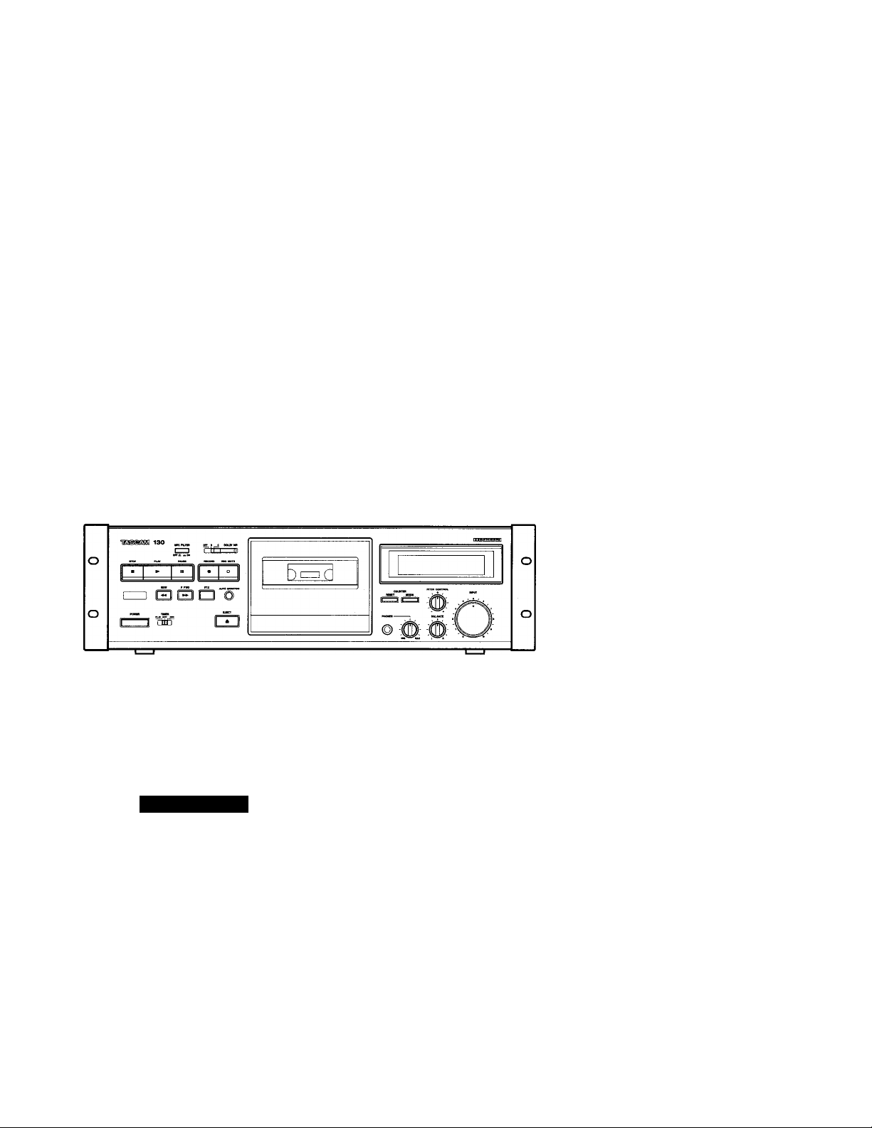
130
Stereo Cassette Deck
3D0017800A
OWNER’S MANUAL
CAUTION
RISK OF ELECTRIC SHOCK
Al
A
A
This appliance has a serial number located
on the rear panel. Please record the model
number and serial number and retain them
for your records.
Model number
Serial number
DO NOT OPEN
---------------------------------------
_______________________
lA
The lightning fiash with arrowhead symboi, within an equilateral triangle, is intended to aiert
the user to the*presence of uninsulated “dangerous voltage” within the product’s enclosure
that may be of sufficient magnitude to constitute a risk of electric shock to persons.
The exclamation point within an equilateral triangle is intended to alert the user to the pres
ence of important operating and maintenance (servicing) instructions in the literature
accompanying the appliance.
CAUTION: TO REDUCE THE RISK OF ELECTRIC SHOCK, DO NOT
REMOVE COVER (OR BACK). NO USER-SERVICEABLE PARTS INSIDE.
REFER SERVICING TO QUALIFIED SERVICE PERSONNEL.
WARNING: TO PREVENT FIRE OR SHOCK
HAZARD, DO NOT EXPOSE THIS
APPLIANCE TO RAIN OR MOISTURE.
Page 2
IMPORTANT SAFETY INSTRUCTIONS
CAUTION:
• Read all of these Instructions.
• Save these Instructions for later use.
• Follow all Warnings and Instructions marked on the audio
equipment.
1) Read Instructions — All the safety and operating instructions should
be read before the product is operated.
2) Retain instructions — The safety and operating instructions should
be retained for future reference.
3) Heed Warnings — All warnings on the product and in the operating
instructions should be adhered to.
4) Follow Instructions — All operating and use instructions should be
followed.
5) Cleaning — Unplug this product from the wall outlet before cleaning.
Do not use liquid cleaners or aerosol cleaners. Use a damp cloth for
cleaning.
6) Attachments — Do not use attachments not recommended by the
product manufacturer as they may cause hazards.
7) Water and Moisture — Do not use this product near water - for
example, near a bath tub, wash bowl, kitchen sink, or laundry tub; in a
wet basement; or near a swimming pool; and the like.
8) Accessories — Do not place this product on an unstable cart, stand,
tripod, bracket, or table. The product may fall, causing serious injury to a
child or adult, and serious damage to the product. Use only with a cart,
stand, tripod, bracket, or table recommended by the manufacturer, or
sold with the product. Any mounting of the product should follow the
manufacturer’s instructions, and should use a mounting accessory rec
ommended by the manufacturer.
9) A product and cart combination should be moved with care. Quick
stops, excessive force, and uneven surfaces may cause the product and
cart combination to overturn.
10) Ventilation — Slots and openings in the cabinet are provided for
ventilation and to ensure reliable operation of the product and to protect
it from overheating, and these openings must not be blocked or covered.
The openings should never be blocked by placing the product on a bed,
sofa, rug, or other similar surface. This product should not be placed in a
built-in installation such as a bookcase or rack unless proper ventilation
is provided or the manufacturer’s instructions have been adhered to.
11) Power Sources — This product should be operated only from the
type of power source indicated on the marking label. If you are not sure
of the type of power supply to your home, consult your product dealer or
local power company. For products intended to operate from battery
power, or other sources, refer to the operating instructions. •
12) Grounding or Polarization — This product may be equipped with a
polarized alternating-current line plug (a plug having one blade wider
than the other). This plug will fit into the power outlet only one way. This
is a safety feature. If you are unable to insert the plug fully into the out
let, try reversing the plug. If the plug should still fail to fit, contact your
electrician to replace your obsolete outlet. Do not defeat the safety pur
pose of the polarized plug.
13) Power-Cord Protection — Power-supply cords should be routed so
that they are not likely to be walked on or pinched by items placed upon
or against them, paying particular attention to cords at plugs, conve
nience receptacles, and the point where they exit from the product.
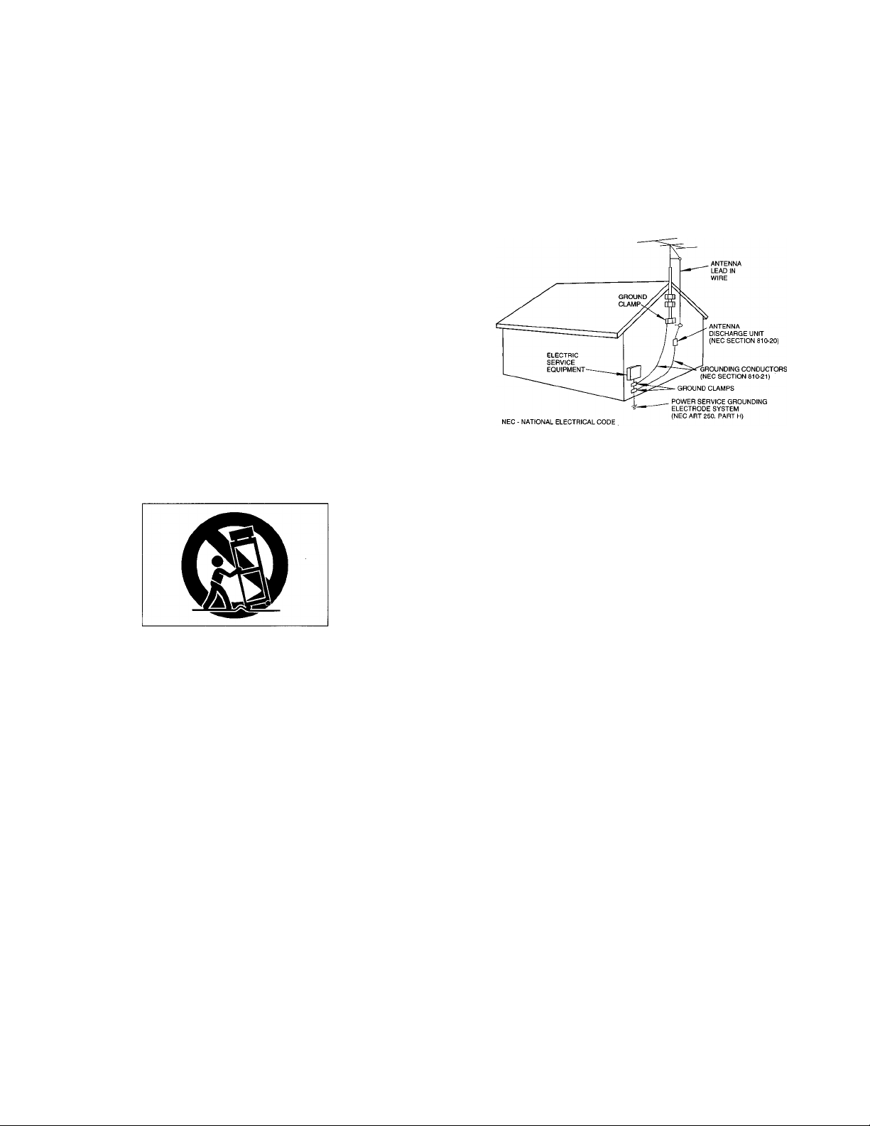
14) Outdoor Antenna Grounding — If an outside antenna or cable sys
tem is connected to the product, be sure the antenna or cable system is
grounded so as to provide some protection against voltage surges and
built-up static charges. Article 810 of the National Electrical Code,
ANSI/NFPA 70, provides information with regard to proper grounding of
the mast and supporting structure, grounding of the lead-in wire to an
antenna discharge unit, size of grounding conductors, location of anten
na-discharge unit, connection to grounding electrodes, and requirements
for the grounding electrode.
"Note to CATV system installer:
This reminder is provided to call the CATV system installer’s attention to
Section 820-40 of the NEC which provides guidelines for proper ground
ing and, in particular, specifies that the cable ground shall be connected
to the grounding system of the building, as close to the point of cable
entry as practical.
Example of Antenna Grounding as per
National Electricai Code, ANSI/NFPA 70
15) Lightning — For added protection for this product during a lightning
storm, or when it is left unattended and unused for long periods of time,
unplug it from the wall outlet and disconnect the antenna or cable sys
tem. This will prevent damage to the product due to lightning and power
line surges.
16) Power Lines — An outside antenna system should not be located in
the vicinity of overhead power lines or other electric light or power cir
cuits, or where it can fall into such power lines or circuits. When installing
an outside antenna system, extreme care should be taken to keep from
touching such power lines or circuits as contact with them might be fatal.
17) Overloading — Do not overload wall outlets, extension cords, or
integral convenience receptacles as this can result in risk of fire or elec
tric shock.
18) Object and Liquid Entry — Never push objects of any kind into this
product through openings as they may touch dangerous voltage points
or short-out parts that could result in a fire or electric shock. Never spill
liquid of any kind on the product.
19) Servicing — Do not attempt to service this product yourself as open
ing or removing covers may expose you to dangerous voltage or other
hazards. Refer all servicing to qualified service personnel.
20) Damage Requiring Service — Unplug this product from the wall
outlet and refer servicing to qualified service personnel under the follow
ing conditions:
a) when the power-supply cord or plug is damaged.
b) if liquid has been spilled, or objects have fallen into the product.
c) if the product has been exposed to rain or water.
d) if the product does not operate normally by following the operating
instructions. Adjust only those controls that are covered by the operating
instructions as an improper adjustment of other controls may result in
damage and will often require extensive work by a qualified technician to
restore the product to its normal operation.
e) it the product has been dropped or damaged in any way.
f) when the product exhibits a distinct change in performance - this indi
cates a need for service.
21) Replacement Parts — When replacement parts are required, be
sure the service technician has used replacement parts specified by the
manufacturer or have the same characteristics as the original part.
Unauthorized substitutions may result in fire, electric shock, or other haz
ards.
22) Safety Check — Upon completion of any service or repairs to this
product, ask the service technician to perform safety checks to deter
mine that the product is in proper operating condition.
23) Wall or Ceiling Mounting — The product should be mounted to a
wall or ceiling only as recommended by the manufacturer.
24) Heat — The product should be situated away from heat sources
such as radiators, heat registers, stoves, or other products (including
amplifiers) that produce heat.
-2-
Page 3
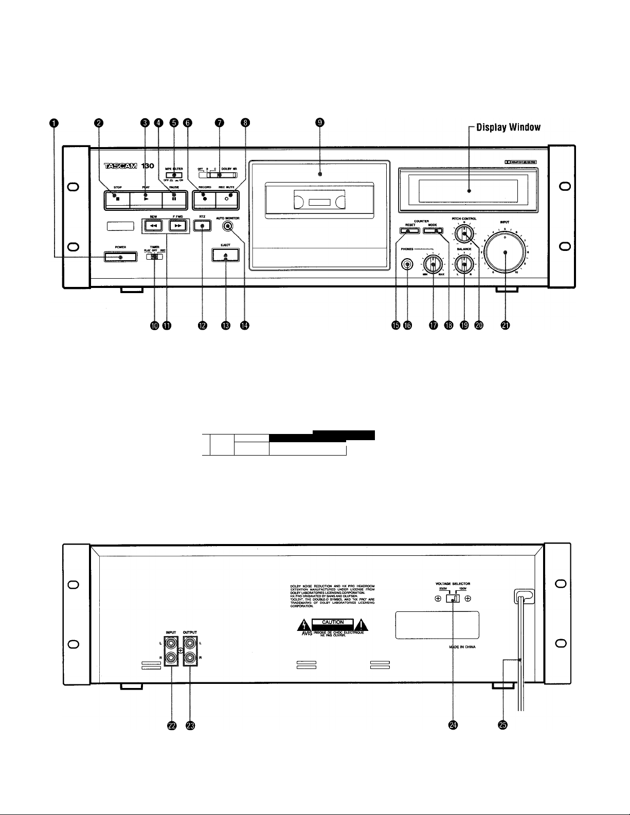
Reference Illustrations
Fig.1
Front Panel
Display Window
Rear Panel
dB -oo 40 30 20 10 7 5 3 2 00 0 1 2 3 5 7 +10
CEDiiiiiiiMiiiiiiiiiiiMiiiiiiiiiiiHiimiiiiiiiimmiiiiiiiiiiiiiiiiiiiiiiiiiiiiiii
TAPE
|MPX FILTER||HX PRO|
DOLBY NR
LI L/m LI Lh
► I I
n
Eiaa SOURCE
Page 4

Fig. 2
stereo amplifier
Fig. 4
Fig. 6
Amplifier
o o O O: O Ò:
Voltage Conversion
Ù
QO I CP I CD I S-1 -3 I -3
Fig. 5
Capstan Pinch Roller
Tuner
Spare AC outlet
ll-l-l - I
Cassette deck
G) CD CD O
1 Sf
Audio timer
□ig I AC
power
Page 5

Precautions
Connections (Fig. 2)
Features and Controis (Fig.i)
Environment
Avoid using the deck in the following cir
cumstances:
• High temperature (such as heater, direct
sunlight).
• Extremely low temperature.
• Excessive humidity.
• Dusty atmosphere.
• Where power line voltage fluctuation is
severe (the use of a voltage regulator may
be advisable).
• Be aware also that placing other units or
any objects on the deck can leave marks
depending on their weight.
Cassene Tape (Fig. 3)
Tape Selection:
For the automatic tape select function to
work properly, metal and chrome (cobalt)
formula tapes must have tape identification
holes.
C-120 cassette tapes:
120-minute tapes are very thin, they tend
to stretch and their magnetic layer is thin;
they also tend to introduce wow & flutter.
For these reasons, special attention is
required when using them. If the pinch
roller or capstan is dirty, tape might become
wrapped around it and this could cause
serious trouble. For this reason, it is re
commended that you do not use C-120
tapes.
Tape Handling:
Do not store tape in the following places:
• On top of heaters, in direct sunlight or in
any other high-temperature areas.
• Near speakers, on TV sets or amplifiers or
near any strong magnetic fields.
• High-humidity areas or dirty, dusty areas.
Avoid dropping or subjecting the cassettes
to excessive shock.
Voltage Conversion (For general export models) (Fig. 4)
Be sure to remove the povi/er cord from the
AC outlet before repositioning the voltage
converter switch.
1. Locate the voltage selector on the rear
panel.
2. Using a flat-bladed screwdriver, set to
the appropriate 230 V or 120 V position
according to your area.
• Turn off power for all equipment before
making connections.
• Read instructions for each component
you intend to use with the deck.
IMPORTANT
(for U.K. customers)
DO NOT cut off the mains piug from
this equipment. If the plug fitted is not
suitable for the power points in your home
or the cable is too short to reach a power
point, then obtain an appropriate safety
approved extension lead or consult your
dealer.
If nonetheless, the mains oluo is cut off.
remove the fuse and dispose of the pIuq
immediately, to avoid a possible shock
hazard by inadvertent connection to the
mains supply.
If this product is not provided with a mains
plug, or one has to be fitted, then follow
the instructions given below:
IMPORTANT. DO NOT make any
connection to the larger terminal which is
marked with the letter E or by the safety
earth symbol or coloured GREEN or
GREEN-and-YELLOW.
The wires in the mains lead on this
product are coloured in accordance with
the following code:
BLUE
BROWN
As these colours may not correspond with
the coloured markings identifying the
terminals in your plug proceed as follows:
The wire which is coloured BLUE must be
connected to the terminal which is marked
with the letter N or coloured BLACK.
The wire which is coloured BROWN must
be connected to the terminal which is
marked with the letter L or coloured
RED.
When replacing the fuse, only a correctly
rated approved type should be used and
be sure to re-fit the fuse cover.
IF IN DOUBT — CONSULT A
COMPETENT ELECTRICIAN.
Dolby noise reduction and HX Pro
headroom extension manufactured under
license from Dolby Laboratories Licensing
Corporation. HX Pro originated by Bang
& Olufsen.
"DOLBY", the double-D symbol □□ and
"HX PRO" are trademarks of Dolby
Laboratories Licensing Corporation.
NEUTRAL
LIVE
Freni Panel
O POWER Switch
Press to switch the deck on. The display
window will be illuminated. Press again to
turn the deck off.
Note: Be sure to wait more than 2 seconds
after the power has been switched
off before switching the power on
again.
0STOP Button
Press to stop the tape travel and release
any other mode.
0 PLAY Button
Pressing this button starts normal-speed
playback.
O PAUSE Button
Press to temporarily stop tape travel during
recording or playback. In the pause mode,
the PAUSE indicator in the display lights.
Press the PLAY button or PAUSE button
again to restart the tape (the indicator
goes out).
©MPX FILTER Switch
Press this switch when making a Dolby NR
recording of an FM broadcast; the indicator
lights. It eliminates the pilot tone (19 kHz)
and subcarrier tone (38 kHz) of the FM
broadcast which could affect operation of
the Dolby noise reduction system. To re
lease this function, press the MPX FILTER
switch again.
0 RECORD Button
Press the RECORD button to set the deck
to the record-pause mode. The REC and
PAUSE indicators will light. To start record
ing, press the PLAY button or PAUSE button.
O DOLBY NR Switch
OFF: Set to this position when you do not
want to use any noise reduction
system.
B: Set to this position when making a
recording using the Dolby B noise
reduction system, or playing back
tapes recorded with Dolby B NR.
C:Set to this position when making a
recording using the Dolby C noise
reduction system, or playing back
tapes recorded with Dolby CNR.
0 REC MUTE Button
Press this button during recording to leave
a blank section between tunes (approx. 4 se
conds). The deck will enter the recordpause mode. Press the PLAY button or
PAUSE button to start recording again.
(See page 7.)
-5 -
0 Cassette Holder
Load the cassette here.
Page 6

0 TIMER Switch
PLAY: For timer playback
OFF: Set to this position when not using
a timer.
REC: For timer recording
(See page 8.)
(D REW (Rewind) Button/ ►►
F FWD (Fast-Forward) Button
When these buttons are pressed, the tape is
rewound or fast-forwarded.
0 RTZ (Return to Zero) Button
If this button is pressed, the tape is fastforwarded or rewound until a tape counter
reading of "0000" is reached, then the
deck stops. (See page 8.)
0 EJECT Button
Press in the stop mode to open the cassette
holder. Do not press this button when the
deck is in the recording or playback mode.
0AUTO MONITOR Button
This button allows you to select which
signal is to be monitored with its level
displayed on the meter. When power is
applied to the deck, the monitor mode is
set to TAPE, showing that the signal recorded
on the tape is monitored with its level
displayed by the meter. When the deck
enters the record-pause mode, the monitor
mode is automatically switched to SOURCE,
showing the signal input to the deck (from
the INPUT jacks on the rear panel) is
monitored with its level displayed. And
when the record-pause mode is released,
it is automatically changed to TAPE.
To manually change the monitor mode,
press this button.
0 RESET Button
Pressing the RESET button resets the
multi-counter to “0000”.
0 PHONES Jack
Connect 8-ohm stereo headphones to this
jack for private listening or monitoring.
0 PHONES level Control
Adjust the level of the signals output from
the PHONES jack. This knob does not
affect the level of the signals output from
the OUTPUT jacks on the rear panel or the
level indicated by the peak level meter.
0 MODE Button
When this button is pressed, the display
alternates between the conventional tape
counter and the TRT (tape-run-time)
counter.
0 BALANCE Control
Adjust the balance of the left and right
channels of the input signals to be recorded
on tape.
0 PITCH CONTROL
You can change the tape speed during
playback, allowing to change the pitch of
the reproduced sound.
By turning the PITCH CONTROL to the right,
the tape speed becomes faster, resulting in
higher pitch. By turning it to the left, the
tape speed becomes slower, resulting in
lower pitch.
. At the fully clockwise position, the tape
speed is approx. 10% faster.
• At the fully counterclockwise position,
the tape speed is approx. 10% slower.
0 INPUT level Control
When recording, turn the INPUT level con
trol clockwise to fade the input sound in or
turn it counterclockwise to fade the sound
out, for smooth tune-to-tune transitions.
Display Window
® Peak Level Meter
This meter shows the peak level of the input
or playback signal. In the record mode,
the meter indicates the level of the source
signals which have been adjusted with the
INPUT level and BALANCE controls.
During playback, the meter indicates the
level of signals recorded on the tape.
d) Tape Type Indicator
The deck automatically detects the type of
tape which has been loaded, and these
indicators (NORMAL, CrO^ and METAL)
indicate the type of tape being used.
© Multi-Counter
Tape Counter Mode
In this mode, the counter functions as a
conventional tape counter, counting up
when the tape is moving forward and down
when the tape is being rewound. The dis
play can be cleared by pressing the RESET
button, which resets the counter index to
“
0000".
n n n n
LI LI LI LI
TRT (Tape-Run-Time) Counter Mode
In this mode, tape travel is measured in
minutes and seconds up to a maximum of
99M59S (99 minutes 59 seconds). Since this
counter only functions in the play and re
cord modes, it will be interrupted when the
tape is fast-forwarded or rewound (and, of
course, in the stop mode); counting up will
be resumed when playback or recording
restarts. The display can be cleared by
pressing the RESET button which resets
counter index to "OOMOOS".
n n n n
LI L/m LI Us
©Transport Mode Indicators
»¿TJJ: Lights when the deck is in the re
cord and record-standby modes, and
flashes during record-muting.
► (PLAY): Lights when the deck is in the
playback and record modes.
II (PAUSE): Lights when the deck is
standing by for playback or recording.
©Auto Monitor Indicators
TAPE: Lights when the tape signal is
selected either in playback or record.
SOURCE: Lights when the source signal is
selected.
The Auto Monitor indicators change auto
matically to the monitor mode so that the
SOURCE indicator lights when the deck
enters the record-pause mode. When record
ing starts, the SOURCE indicator auto
matically goes out and the TAPE indicator
lights.
©MPX FILTER Indicator
Lights when the MPX FILTER switch is
pressed in ( a ).
© HX PRO Indicator
Lights when the deck enters the record
mode, showing that the built-in Dolby HX
Pro circuit has been activated. For details,
refer to page 9.
©DOLBY NR [B] [C] Indicator
Lights when the DOLBY NR switch is set
to the B or C position.
Rear Panel
0 INPUT Terminals
Connect the amplifier's REC OUT jacks to
these jacks.
0 OUTPUT Terminals
Connect the amplifier's TAPE PLAY or
LINE IN jacks to these jacks.
0 Voltage Selector (General Export
Models Only)
See "Voltage Conversion" on page 5.
0 Power Supply Cord
Insert into an AC wall outlet, etc. The
voltage required by this unit is shown on
the rear panel.
-6-
Page 7

Operations
Playback ana Recording
Stereo Playback
1. Set the TIMER switch to OFF.
2. Press the POWER switch to ON.
3. Load a pre-recorded cassette.
4. Select the NR system with the DOLBY
NR switch.
5. Press the PLAY button to start playback.
6. Adjust the volume with the amplifier's
control.
Stereo Recording
1. Set the TIMER switch to OFF.
2. Press the POWER switch to ON.
3. Load a recordable cassette.
4. Select the required NR system with the
DOLBY NR switch.
5. Press the MPX FILTER switch to IN
when making a Dolby NR recording of
an FM broadcast.
6. Press the RECORD button {both the
REC and PAUSE indicators light). This
enables you to adjust the recording level
without actually recording on the tape.
7. Adjust the INPUT level and BALANCE
controls so that the loudest peak briefly
reaches the meter reference reading for
the type of tape used for both channels.
8. Press the PLAY button or PAUSE button
to start recording. The REC and PLAY
indicators light.
The Auto Monitor indicator is auto
matically changed to TAPE and the
signal can be directly monitored im
mediately after it is recorded. To com
pare the recorded sound with the
original source, press the AUTO
MONITOR button to switch the signal
being monitored between TAPE and
SOURCE.
AUTO MONITOR
Notes:
• To stop recording, press the STOP button.
• To momentarily stop recording, press the
PAUSE button. To resume recording, press
the PLAY button or PAUSE button.
Note:
Recording prerecorded tapes, records, or
other published or broadcast material
may infringe copyright laws. Check
these laws before recording.
Setting the Recording Levei
Setting the recording level correctly is es
sential if you want to make top-quality
recordings. If the level is too low, the
recording will be noisy. If the level is set
too high, the recording will be distorted.
Generally speaking, the recording level
should be set so that the loudest peak to be
recorded makes the meters briefty indicate
the meter reference reading for the type of
tape used. If the meters peak over the
reference reading, decrease the recording
level by turning the INPUT level control
counterclockwise. However, some program
material or different tape formulations may
require higher or lower recording levels.
With a little time and practice you will be
able to select the critical recording level
that gives you the best hi-fi recordings. The
optimum setting of the recording level will
differ according to the type and condition
of the tape, as well as the type of music
you are recording.
Erasing
A previously recorded tape will be auto
matically erased when you make a new
recording on it. Alternatively it can be
erased by "recording" on it with the INPUT
level control set to "0".
Record Muting Operation
The ability to leave blank unrecorded
(erased) portions on a tape during recording
is a real advantage in many recording
situations. For instance, you may want to
eliminate undesired portions of an FM
broadcast that you are recording, such as
commercials, station breaks or announce
ments. You may want to record a complete
program with controlled spacing between
each song. Such blank portions on a tape
can be easily left using the REC MUTE
function.
• Automatic Spacing operation — for a 4-second blank — (during recording or record-pause mode)
Press the REC MUTE button during the
recording or record-pause mode. The
tape continues to run, and a blank
space of about 4 seconds is recorded
(the REC indicator flashes).
The deck then switches automatically to
the record-pause mode (both the REC
and PAUSE indicators light). To start
recording the next tune, press the
PLAY button or PAUSE button (both the
REC and PLAY indicators light).
• For a Blank of More Than 4 Seconds
During recording, keep the REC MUTE
button pressed for a longer blank period.
Release the button to enter the recordpause mode. To begin recording, press
the PLAY button or PAUSE button.
• For a Blank of Less Than 4 Seconds
After pressing the REC MUTE button
during recording, press the PAUSE button,
before the 4-second interval has elapsed,
to cancel the muting mode and engage
the record-pause mode. To begin record
ing, press the PLAY button or PAUSE
button.
Multi-Counter Function
With the multi-counter facilities incorporat
ed in the unit, there are two different dis
play modes available, depending on the
setting of the MODE button.
Tape Counter Mode: The counter functions
as a conventional tape counter.
TRT Counter mode: The counter functions
as a tape-run-time counter, measuring tape
travel in minutes and seconds.
Using as a Tape Counter
Using the MODE button, call up the tape
counter mode; a 4-digit display will appear.
Its function is identical to that of a conven
tional tape indexing counter. During re
cording (including record muting), playback
and fast-forward, the counter counts up as
the tape moves from left to right, and down
during rewind as the tape moves from
right to left. The indicated numerals are
not related to elapsed time and are not
compatible with the counter readings of
other cassette decks. One typical example
of using this display in the conventional
tape counter mode is: First load a cassette
and before recording, press the RESET
button to reset the counter to "0000".
Then note the counter reading at the begin
ning of each piece of music to facilitate
locating that particular selection when
you wish to play it back.
-7-
Page 8

Maintenance (Fig. 5)
Using as a TRT Counter
Using the MODE button, call up the taperun-time mode; "M" appears between the
2nd and 3rd digits and "S" at the end of
the 4th digit. In this mode, tape travel is
measured in minutes and seconds while
the tape is running at normal speed during
recording (including record muting) and
playback. Counting stops during rewind
and fast-forward. This function can be
used to measure the approximate length
of a recorded song or to make an estimate
of how much tape is left.
"Visible" and "Invisible" Counters
Both counter modes are switchable at any
time, with the one selected appearing on the
display and the other functioning in memo
ry. For example, when the conventional
tape counter is selected with the MODE
button, counting of the tape-run-time
also takes place and its reading can be
called up at any time by pressing the MODE
button. Pressing the RESET button resets
only the counter which is currently display
ed. Both counters, "visible" and "invisible"
are reset when power is switched off.
RTZ (Return To Zero) Function
To locate the position on the tape corres
ponding to a tape counter reading of
"0000", press the RTZ button.
The fast-forward or rewind of the tape
starts. When a counter reading of "0000"
is detected, the deck stops.
This function is handy to locate the begin
ning of tune to be played back.
Timer-Conlroned Operations (Fig. 6)
Timer-Controlled Recording
1. Connect your deck and stereo system to
a commercially available audio timer as
shown in the diagram.
2. Make all the preparations as for normal
recording, but leave the deck in the stop
mode.
3. Set the audio timer to the required
start (power on) and stop (power off)
times.
4. Set the TIMER switch on the deck to
REC.
When the preset start time is reached,
power will be supplied and recording
will start.
Timer-Controlled Playback
1. Check that the deck is correctly con
nected to the amplifier for normal
playback operation.
2. Connect the deck and amplifier to an
audio timer as for timer-controlled re
cording (above).
3. Make all preparation as for normal play
back, but leave the deck in the stop
mode.
4. Set the audio timer to the required
start (power on) and stop (power off)
times.
5. Set the TIMER switch on the deck to
PLAY.
When the preset start time is reached,
power will be switched on and playback
will start.
Note: Be sure to set the TIMER switch to
OFF after timer-controlled recording
or playback is over.
The heads and tape path should be cleaned
and demagnetized periodically.
Cleaning Tape Path
• Apply head cleaning fluid* * to special
cotton swabs or a soft cloth, and lightly
rub the heads, capstans and all metal parts
in the tape path.
• Also clean the pinch rollers using rubber
cleaning fluid*.
• Both are available in TEAC HC-2 and
RC-2 in the U.S.A. or TEAC TZ-261
Tape Recorder Cleaning Kit in other
areas.
Demagnetizing Heads
Be sure that the power is off, then demag
netize the heads using a TEAC E-3 demagnetizer or equivalent. For details of its
use, read its instructions.
Troubleshooting
Basic troubleshooting of a cassette tape
deck is similar to troubleshooting any other
electrical or electronic equipment. Always
check the most obvious possible causes first.
To give you a few ideas of what to look for,
check the following:
• No power: Is the power cord connected?
• Tape begins running when power is turned
on: Is the TIMER function on?
• No audio output; Are all connections
properly made?
• Degraded sound quality: Are the heads
dirty or magnetized? Are you using
good quality tape? Is the proper NR
System select switch on?
• Unable to select record mode: Are the
record protection tabs on the tape in
place?
Rewind
To start playback from "0000":
While the tape is running after the RTZ
button is pressed, press the PLAY button.
The deck temporarily stops at the "0000"
counter reading, then playback starts.
To release the RTZ function:
Press the STOP button. If the (rewind)
or ►► (fast-forward) button is pressed
while the tape is running after the RTZ
button is pressed, the RTZ function is re
leased, and the deck enters the normal
rewind or fast-forward mode.
*The RTZ button cannot be used when the
deck is in the recording mode or near
the "0000" counter reading.
Fastforward
8-
Page 9

DOLBY HX PRO
Specifications
Dolby HX Pro is an "active bias" technique
that can improve the quality of audio tape
recordings. High-level high frequencies can
be recorded more accurately, without
sacrificing signal-to-noise ratio, while such
side effects of tape saturation as distortion
are reduced.
What Is Bias?
Bias is a very high-frequency signal generat
ed within a tape deck and recorded on the
tape simultaneously with the program
material. This inaudible signal allows a low
noise, low distortion recording and flat
frequency response. Different magnetic tape
formulations require different amounts
of bias for optimum performance. If the
bias level is too high, high-frequency
Maximum Output Level (MOL) decreases.
The Problem of Self-Bias
Unfortunately, bias level is often influenced
by the signal being recorded. The high fre
quencies contained in some music act as
bias. This unpredictable source of bias is
added to the existing bias, resulting in a loss
of high-frequency response. As the high-
frequency content of the signal increases.
the ability of the recorder to record high
frequencies (MOL) decreases. This pheno
menon is called self-biasing.
The Dolby HX Pro Solution
The Dolby HX Pro monitors the highfrequency content of the program material
and adjusts the recorder bias oscillator to
maintain a constant total bias level. The
result is improved high-frequency response
and lower distortion. Depending on the type
of tape, the improvement in headroom can
be 6 dB or more.
The Benefits
With Dolby HX Pro, it is easier to make
more accurate recordings of tbe kind of
music which contains high-level high fre
quencies. The improvement is similar to
that of high-performance tape over conven
tional tape, so regardless of the type of
tape used, the results will sound better.
Most important of all, Dolby HX Pro
requires no decoding process. Once the
tape is recorded with it, the improvements
will be realized when playing the tape back
on any machine.
Track System 4-Track, 2-Channel Stereo
Heads 3: 1 Erase, 1 Record and 1
Playback (Combination)
Type of Tape Cassette tape C-60 and C-90
(Philips type)
Tape Speed 4.8 cm/sec. (1-7/8 ips)
Motors 2: 1 DC Servo motor
(for capstan drive)
1 DC motor
(for reel drive)
Wow and Flutter
0.045 % (W. RMS)
Frequency Response (Overall) -20 dB
15 - 21,000 Hz ±3 dB Metal Tape
15 - 20,000 Hz ±3dBCrO, Tape
15 - 18,000 Hz ±3 dB Normal Tape
Signal-to-Noise Ratio (Overall)
60 dB (NR OFF, 3% THD Level,
Weighted)
70 dB (Dolby B In, over 5 kHz)
80 dB (Dolby C In, over 1 kHz)
Fast Winding Time Approximately 90
seconds for C-60
Inputs Line; 97 mV, 50k ohms
Outputs Line; 0.58 V for load impedance
of 50k ohms or more
Headphones; 1 mW/8-ohm load
Power Requirements 120/230 V
AC, 50 - 60 Hz (General export
models)
120 VAC, 60 Hz (U.S.A./Cariada)
230 V AC, 50 Hz (Europe)
240 V AC, 50 Hz (Australia)
Power Consumption 15 W
Dimensions (W x H x D)
483X140 X 289 mm
(19"X 5-1/2" X 11-3/8")
Weight 4.5 kg (9.94 lbs.)
Standard Accessories
Rack mounting screw kit
20Hz 50 100 200 500 1 k 2 5 10 20k
Example of improved frequency response using Dolby HX Pro function
• Specifications were determined using metal
tape except as noted.
• Improvements may result in specifications
or features changing without notice.
• Photos and illustrations may differ slightly
from production models.
Since this unit incorporates micro
computers, it may not operate correctly
because of external noise, etc. In such a
case, confirm that the TIMER switch is in
the OFF position, then switch off the
power once for approx, one minute
before restarting operation from the
beginning.
-9 -
Page 10

For U.S.A.
TO THE USER
This equipment has been tested and found to comply with the limits for a Class B digital device, pursuant to Part 15
of the FCC Rules. These limits are designed to provide reasonable protection against interference in a residential
area. This device generates and uses radio frequency energy and if not installed and used in accordance with the
instructions, it may cause interference to radio or TV reception. If this unit does cause interference with TV or radio
reception you can try to correct the interference by one or more of the following measures;
a) Reorient or relocate the receiving antenna.
b) Increase the separation between the equipment and the receiver.
c) Plug the equipment into a different outlet so that it is not on the same circuit as the receiver.
If necessary, consult the dealer or an experienced radio/TV technician for additional suggestions.
CAUTION:
Changes or modifications to this equipment not expressly approved by TEAC CORPORATION for compliance could
void the user's authority to operate this equipment.
For CANADA
AC POWER CORD CONNECTION CORDE DE CONNEXION CA
CAUTION: ATTENTION:
TO PREVENT ELECTRIC SHOCK, MATCH WIDE POUR ÉVITER LES CHOCS ÉLECTRIQUES, INTROBLADE OF PLUG TO WIDE SLOT, FULLY INSERT. DUIRE LA LAME LA PLUS LARGE DE LA FICHE
DANS LA BORNE CORRESPONDANTE DE
LA PRISE ET POUSSER JUSQU’AU FOND.
TEAC CORPORATION
TEAC AMERICA, INC.
TEAC CANADA LTD.
TEAC MEXICO, S.A. De C.V
TEAC UK LIMITED
TEAC DEUTSCHLAND GmbH
TEAC FRANCE S. A.
TEAC BELGIUM NV/SA
TEAC NEDERLAND BV
TEAC AUSTRALIA PTY., LTD.
A.C.N. 005 408 462
TEAC ITALIANA S.p.A.
3-7-3, Nakacho, Musashino-shi, Tokyo 180-8550, Japan Phone: (0422) 52-5082
7733 Telegraph Road, Montebello, California 90640 Phone: (213) 726-0303
340 Brunei Road, Mississauga, Ontario L4Z 2C2, Canada Phone: 905-890-8008
Privada De Corina, No.18, Colonia Del Carmen Coyoacon, Mexico DF 04100 Phone: 5-658-1943
5 Marlin House, Martins Meadow, The Croxiey Centre, Watford, Herts. WD1 8YA, U.K. Phone: 01923-819699
Bahnstrasse 12, 65205 Wiesbaden-Erbenheim, Germany Phone: 0611-71580
17 Rue Alexis-de-Tocqueville, CE 0.05 92182 Antony Cedex, France Phone: 01.42.37.01.02
P.A. TEAC Nederland BV, Perkinsbaan 11a, 3439 ND Nieuwegein, Netherlands Phone: 0031-30-6048115
Perkinsbaan 11a, 3439 ND Nieuwegein, Netherlands Phone: 030-6030229
106 Bay Street, Port Melbourne, Victoria 3207, Australia Phone: (03) 9644-2442
Via C. Canto 11, 20092 Cinisello Balsamo, Milano, Italy Phone: 02-66010500
PRINTED IN CHINA 0498
 Loading...