

Page 1

TASCAM
TEAC Professional Division
122MKHI/
112RMKlI/112MKn
stereo Cassette Deck
TASCAM 122MK1D
h38.Sg.Kl~
I
I
t
□
w
r^i II “irnnnnrsn
n
TASCAM 112RMKD
□
rs~irs~ir5~|| > II . ini~o~||
TJ
TASCAM 112MKH
□
(!)
|i^rsir^f^nnni°l
u
B cs
o o o
C3 ED ED
o o o
B IE] [E]
W W ‘Qffi'
|-SSU9g.g| ■■■°
0 0 o
CE]
s d: cè]
CED cm TffiT
g8gggl"'°
El ra
ED ED ED
"Sd QD Tltn
:
n
:
o o
:
IT
O o
IT
c
OWNER'S MANUAL
9101409300
Page 2

THE APPLIANCE CONFORMS WITH EEC DIREC
TIVE 87/308/EEC REGARDING INTERFERENCE
SUPPRESSION
CONFORME AL D.M. 13 APRI LE 1989
DIRETTIVA CEE/87/308
Bescheinigung des Herstellers/Importeurs
Note for U.K. Customers
Due to the variety of plugs being used in the U.K., this
unit is sold without an AC plug. Please request your dealer
to install the correct plug to match the mains power outlet
where your unit will be used as per these instructions.
IMPOflTANT
The wires in this mains lead are coloured in
accordance with the following code:
Hiermit wird bescheinigt, daß der/die/das
Stereo Kassetten-Rekorder 122 MKIII/112R MKII/112 MKII
(Gerät, Typ, Bezeichnung)
in Übereinstimmung mit den Bestimmungen der
AMTSBLATT 163/1984, VFG 1045/1984, VFG 1046/1984
(Amtsblattverfügung)
tunk-entstört ist.
Der Deutschen Bundespost wurde das Inverkehrbringen
dieses Gerätes angezeigt und die Berechtigung zur Über
prüfung der Serie auf Einhaltung der Bestimmungen eingeräumt.
TEAC CORPORATION
Name des Herstellers/Importeurs
For CANADA
AC POWER CORD CONNECTION CAUTION:
TO PREVENT ELECTRIC SHOCK, MATCH WIDE
BLADE OF PLUG TO WIDE SLOT, FULLY INSERT.
NEUTRAL
BROWN:
As the colours of the wires in the matrss lead of
this apparatus may not correspond with the
coloured markings identifyifig the terminal in your
plug, proceed as follows:
The wire which is coioured blue must be
connected to the terminal which is marked with
the ietter N or coloured BLACK. The wire which
is coloured BROWN .must be connected to the
terminal which is marked with the letter L or
coioured RED.
CORDE DE CONNEXION CA ATTENTION:
POUR ÉVITER LES CHOCS ÉLECTRIQUES,
INTRODUIRE LA LAME LA PLUS LARGE DE LA
FICHE DANS LA BORNE CORRESPONDANTE DE
LA PRISE ET POUSSER JUSQU'AU FOND.
LIVE
CAUTION: TO REDUCE THE RISK OF ELECTRIC SHOCK. DO NOT REMOVE COVER
(OR BACK). NO USER-SERVICEABLE PARTS INSIDE. REFER SERVICING TO
QUALIFIED SERVICE PERSONNEL.
A
CAUTION
RISK OF [LECTRIC SHOCK
DO NOT OPEN
A
The lightning flash with arrowhead symbol, within an equilateral triangle, is intended to alert the user
A
to the presence of uninsulated “dangerous voltage” within the product’s enclosure that may be of
sufficient magnitude to constitute a risk of electric shock to persons.
The exclamation point within an equilateral triangle is intended to alert the user to the presence of
A
This appliance has a serial number located
on the rear panel. Please record the model
number and serial number and retain them for
your records.
Model number
Serial number
_______________
________________
important operating and maintenance (servicing) instructions in the literature accompanying the
appliance.
WARNING: TO PREVENT FIRE OR SHOCK
HAZARD, DO NOT EXPOSE THIS
APPLIANCE TO RAIN OR MOISTURE.
Page 3
SAFETY INSTRUCTIONS
CAUTION:
• Read all of these instructions.
• Save these instructions for later use.
• Follow all warnings and instructions marked on the
audio equipment.
1. Read Instructions — All the safety and operating instructions
should be read before the appliance is operated.
2. Retain Instructions — The safety and operating instructions
should be retained for future reference.
3. Heed Warnings — All warnings on the appliance and in the
operating instructions should be adhered to.
4. Follow Irtstructions — All operating and use instructions
should be followed.
5. Water and Moisture — The appliance should not be used
near water — for example, near a bathtub, washbowl, kitchen
sink, laundry tub, in a wet basement, or near a swimming
pool, etc.
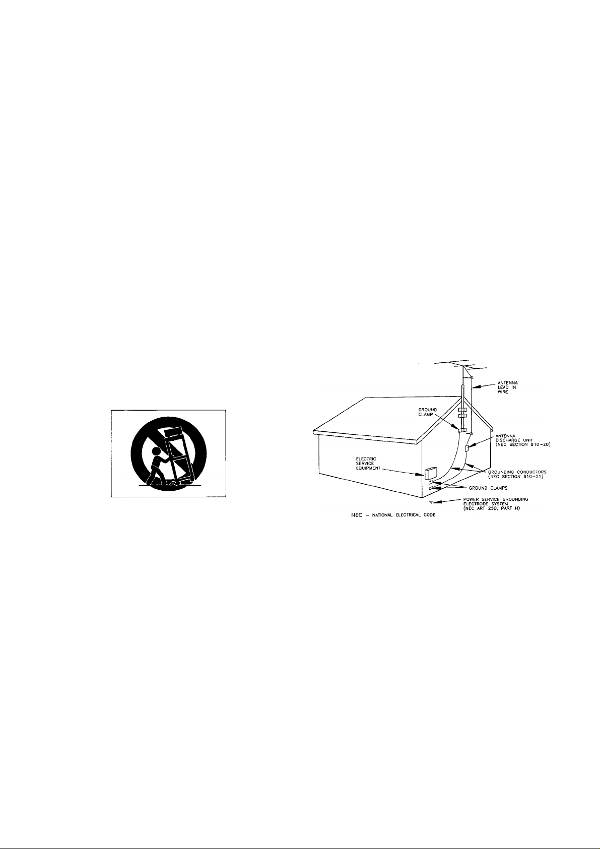
6. Carts and Stands — The appliance should be used only with
a cart or stand that is recommended by the manufacturer.
6A. An appliance and cart combination should be moved with
care. Quick stops, excessive force, and uneven surfaces may
cause the appliance and cart combination to overturn.
13. Cleaning — The appliance should be cleaned only as recom
mended by the manufacturer.
14. Power Lines — An outdoor antenna should be located away
from power lines.
15. Outdoor Antenna Grounding — If an outside antenna is
connected to the receiver, be sure the antenna system is
grounded so as to provide some protection against voltage
surges and built up static charges. Section 810 of the
National Electrical Code, ANSI/NFPA No. 70 — 1984, pro
vides information with respect to proper grounding of the
mast and supporting structure, grounding of the lead-in
wire to an antenna discharge unit, size of grounding con
ductors, location of antenna-discharge unit, connection to
grounding electrodes, and requirements for the grounding
electrode. See Figure below.
EXAMPLE OF ANTENNA GROUNDING
AS PER NATIONAL
ELECTRICAL CODE
7. Wall or Ceiling Mounting — The appliance shouid be mount
ed to a wall or ceiling only as recommended by the manu
facturer.
8. Ventilation — The appliance should be situated so that its
iocation or position does not interfere with its proper venti
lation. For example, the appliance should not be situated
on a bed, sofa, rug, or similar surface that may block the
ventilation openings; or, placed in a built-in installation,
such as a bookcase or cabinet that may impede the flow of
air through the ventilation openings.
9. Heat — The appliance should be situated away from heat
sources such as radiators, heat registers, stoves, or other
appiiances (including amplifiers) that produce heat.
10. Power Sources — The appliance should be connected to a
power supply only of the type described in the operating in
structions or as marked on the appliance.
11. Grounding or Polarization — The precautions that should
be taken so that the grounding or polarization means of an
appliance is not defeated.
12. Power-Cord Protection — Power-supply cords should be
routed so that they are not likely to be walked on or pinch
ed by items placed upon or against them, paying particular
attention to cords at plugs, convenience receptacles, and
the point where they exit from the appliance.
16. Nonuse Periods — The power cord of the appliance should
be unplugged from the outlet when left unused for a long
period of time.
17. Object and Liquid Entry — Care should be taken so that
objects do not fall and liquids are not spilled into the en
closure through openings.
18. Damage Requiring Service — The appliance should be ser
viced by qualified service personnel when:
A. The power-supply cord or the plug has been damaged; or
B. Objects have fallen, or liquid has been spilled into the
appliance; or
C. The appliance has been exposed to rain; or
D. The appiiance does not appear to operate normally or
exhibits a marked change in performance; or
E. The appliance has been dropped, or the enclosure dam
aged.
19. Servicing — The user shouid not attempt to service the
appiiance beyond that described in the operating instruc
tions. All other servicing should be referred to qualified
service personnei.
Page 4
Introduction
Optional Accessories
This manual covers the 122 MKIII, 112R MKII, and 112
MKII.
Your new TASCAM deck is a professional rack-mount 4track, 2-channel recorder/reproducer designed to offer
outstanding audio performance and convenient features.
Speed in operation is, enhanced by CPS (Computomatic
Program Search) (112R MKII only), 2-point Autolocator,
and Retum-to-zero. Dolby* HX Pro is provided to improve
high frequency response. The bias is automatically set to its
optimum value for each tape in use (except for the 122
MKIII). With the 122 MKIII, a built-in oscillator (400 Hz
and 10 kHz) along with individual Bias and Level trimmers
can be used to maximize performance with any tapes. The
3-head design of 122 MKIII and 112R MKII produces real
time, off-tape monitoring.
We suggest that you read this manual thoroughly
before using the machine. Even though a quick glance
will get you going, careful study will ensure that
misunderstanding won't slow you down.
Table of Contents
RC-134 Remote Control Unit
(for 122 MKIII/112 MKII)
Cable length:
5m/15ft
H
TASCAM
RC-134 REMOTE CONTROL UNIT
o n
□ □
RC-112R Remote Control Unit
(for 112R MKII)
Cable length:
5m/15ft
TASCAM
nC-112R REMOTE CONTROL UNfT
pSrnm
Note for U.K. Customers____________________________ 2
Safety Instructions_________________________________3
Introduction
Optional Accessories_______________________________4
Controls and Indicators
Basic Operation__________________________________.10
______________________________________
___________________________
5-9
Recording...........................................................................10
Playback.............................................................................10
Erasing a tape....................................................................10
Special Features
_______________________________
11-14
Autolocator functions..................................................... 11
Repeat play........................................................................12
Recording a blank space between programs
..................
13
Using CPS (Computomatic Program Search)
(112R MKII only)
Bias and Recording Level Calibration
(122 MKIII only)___________________________________15
Dolby HX PRO____________________________________16
Care and Maintenance
Specifications...................................................................17-18
Block Diagrams________________________________19-20
Dolby noise reduction and HX PRO headroom extension
manufactured under license from Dolby Laboratories
Licensing Corporation. HX PRO originated by Bang and
Olufsen. "Dolby", the double-D symbol and "HXPRO"
are trademarks of Dolby Laboratiries Lisensing Corporation.
.............................................................13
____________________________
.16
4
□
□ □ □
LA-112 Balanced Amp/Connector Kit
(for 112 MKII/112 RMKII)
■ PB-32 Series Patch Bay
■ Head Demagnetizer
■ HC-1 Head Cleaner & RC-1 Rubber Cleaner
(U.S. Only)
■ TZ-261 Cleaning Kit
(Except U.S.)
Page 5
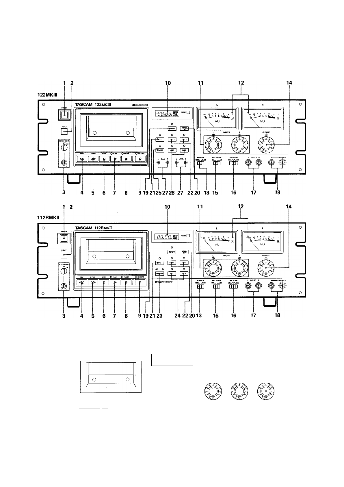
Controls and Indicators
112MKII
1 2
№
d)
TASCAM 112 MKn
QpUtT' QPAUSE QweCOBD
^r^rfiryiryinnri
10 11 12
\g H|—n
1 BB b
o o
ED ED OID
vu
Tim t INPUTS I
u
3 4 5 6 7 8 9 19 21 22 20 13 15 16 17 18
14
u
Page 6

1. POWER : Switches power on to the unit.
NOTE
Each time you turn on the deck, the last on/off status
of the ADJUST switch (122 MKIII only) and Auto
Reverse (CID / ZZD ) switch (112R MKII only) and
the last play/record direction as set with the
DIRECTION switch (112R MKII only) are retrieved from
a backup memory.
2. EJECT : Opens the cassette compartment.
3. PITCH CONT : Provides about a plus or minus 12 %
variation to the tape speed in both Play and Record modes.
Unless you use the function intentionally, make sure that
the knob is at its OFF position for the tape to roll at
normal speed (1-7/8 i.p.s. or 4.8 cm/sec.).
4. REW : Winds the tape at high speed in reverse. If
pressed during Play Pause, enables reverse cueing.
5. F.FWD : Winds the tape at high speed in the forward
direction. If pressed during Play Pause, enables the forward
6. STOP : Stops all tape motion.
122 MKIII and 112R MKII ; The tape counter is not a
clock. Its reading depends on the tape length, relative
tape packs on both reels and other mechanical
factors. Use a watch to measure the correct length of
particular program.
Discrepancy between measurements on the tape
counter and a clock (from beginning to end, one-way
run):
Normal/Cr02
C-30 +3 min. 00 sec. to
4 min. 00 sec.
C-46
C-60
C-90
+1 min.30 sec. to
2 min.45 sec.
-45 sec. to +30 sec.
-1 min.30 sec. to
-30 sec.
C-30/46 measurements made with narrow hub cassettes.
+2 min.OO sec.to
3 min.15 sec.
0 min.OO sec. to
+1 min.15 sec.
-1 min.15 sec. to
0 min. 00 sec.
Metal
—
11. INPUTS, L and R : Allow individual control of both
channel levels.
7. PLAY : Starts playback. If pressed together with
RECORD, starts recording. If pressed during Record Pause,
resumes recording.
8. PAUSE : Temporarily stops play or recording ; to
resume the function interrupted, press PLAY. If pressed
together with RECORD, activates Record Ready mode,
allowing you to start recording by pressing PLAY only.
9. RECORD : Starts recording when pressed together with
PLAY.
10. Tape Counter : Displays the distance from a zero
reference point, selected by pressing RESET (-99 M 59 S
to 99 M 59 S with the 122 MKIII and 112R MKII; or 00
00 to 99 99 with the 112 MKII).
A type of tape in use (NORMAL, Cr02 or METAL) is
indicated on the right hand side of the tape counter, and the
monitor source too—"INPUT" lights unless tape signal is
feeding the front PHONES and rear OUTPUT.
122 MKIII : Both controls are geared together to allow
simultaneous adjustment of the record level of both
channels. Each channel can be adjusted independently by
holding one knob and turning the other.
12. VU meters : indicate input or tape signal levels
depending on the transport mode and the MONITOR switch
setting.
13. MONITOR : Setting to INPUT routes the input
signal to the PHONES and OUTPUT Jacks, whatever the
transport mode. If set to AUTO, the input signal can be
monitored in Record Pause (Ready) mode, and the tape
signal while recording (off-tape monitoring) or playing.
The VU meters also switch the same way.
The 112 MKII does not provide off-tape monitoring ; you'll
hear the input signal instead while recording is taking place.
14. OUTPUT : Adjusts the signal level sent to the
OUTPUT Jacks on the rear panel.
Page 7

15. MPX FILTER : For making Dolby recording of FM
broadcasts. Without this filter, the pilot tone (19 Hz) and
subcarrier note (38 kHz) contained in FM programs may
"thwart" the DOLBY NR system.
16. DOLBY NR : Selects the Dolby B or C Noise
Reduction system or defeats them.
17. INPUTS, L and R : These 1/4" jacks accept
unbalanced line-level signals.
NOTE
Connecting signals to the front input jacks defeats the
rear input jacks. You cannot use both jacks at one
time.
18. PHONES : The knob adjusts the listening level in the
headphones plugged into the adjacent jack.
19. REPEAT : Initiates repeat play between Memo 1 and
Memo 2 (p.l2)
!CF DIRECTION cannot operate during :
O Repeat play
O Search with LOG or CPS
o Fast cueing
o 4-second blank recording
O” If pressed while in F.FWD or REW, switches the tape
side to play (or record) only when the tape reaches the
end or beginning or when stop is pressed.
24. Auto Reverse (112R MKII only) : In one-time,
auto-reverse mode ( ), both sides of the tape play or
record and stop. But, if play or record starts on the reverse
tape side, only that tape side plays or records and stops.
In continuous reverse mode ( ctld ), the entire tape plays
up to five times and stops, or both sides of the tape record
and stop.
25. ADJUST (122 MKIII only) : If pressed when
MONITOR is set to AUTO and the transport is in Record
mode, allows you to press the OSC and 10 kHz switches
and to "fine tune" the BIAS and LEVEL settings. For more
details, see page 15.
20. MEMO IN ; If pressed together with LOG 1 or 2,
stores the current tape point into memory.
cr MEMO IN cannot operate during repeat play or when
the tape is fast-winding as a result of pressing either
LOG.
21. RTZ : Fast-winds the tape at either direction, stopping
when the tape counter reads 00 00. Inertia may carry the
tape slightly past the 00 00 point.
22. LOC, 1 and 2 : Locate the tape to Memo 1 and
Memo 2 points, respectively.
23. DIRECTION (112R MKII only) : Switches over
the tape side to play or record.
Pressing26. OSC and 10 kHz (122 MKIII only)
OSC after ADJUST allows you to get 400 Hz or 10 kHz
oscillator signals for BIAS and LEVEL adjustments (you
get a 400 Hz signal unless you press the 10 kHz switch).
27. BIAS/LEVEL trimmers (122 MKIII only) : For
precise calibration of the bias/record levels to the tape being
used.
Page 8

□ The Rear Panel
28 29 30
33
28. INPUT XLR-type jacks : Accept +4 dBm balanced
signals. Pin assignment : Pin 1 is shield (ground). Pin 2 is
Hot (+), and Pin 3 is Cold (-).
29. INPUT UNBAL/BAL switch : Selects either the
XLR-type or RCA input jacks.
30. OUTPUT XLR-type Jacks : Transmit +4 dBm
balanced signals to your mixer, monitor amp, etc. Pin
assignment: Pin 1 is shield (ground). Pin 2 is Hot (+), and
Pin 3 is Cold (-).
31. OUTPUT RCA jacks : Transmit -10 dBV
unbalanced signals.
32. INPUT RCA jacks : Accept -10 dBV unbalanced
signals.
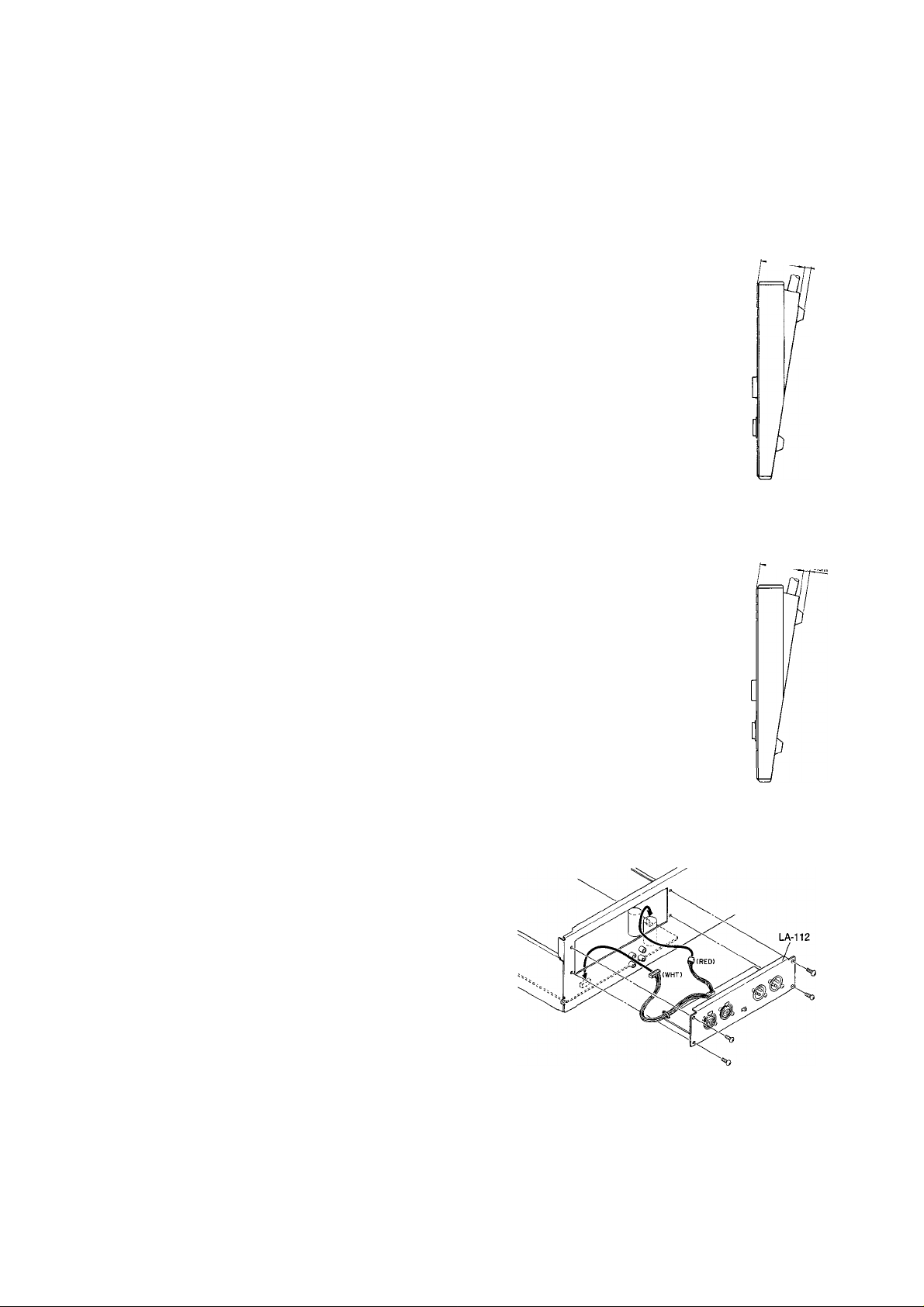
33. Blank Panel (except 122 MKIII) : Space for
mounting an optional balanced amp kit (LA-112).
8
When the LA-112 is installed, you who are using the
112R MKII/112 MKII will have access to the INPUT
XLR-type jacks (#28), the INPUT UNBAL/BAL switch
(#29) and the OUTPUT XLR-type jacks (#30) as with the
122 MKHI.
34. REMOTE CONTROL connector : This 25-pin D-
sub connector is for controlling the transport from the
optional remote RC-112R (for 112R MKII) or RC-134 (for
122 MKIII and 112 MKII), or for fader start from a mixer.
A 25-pin connector (Part No. 53363571-00) and its jacket
(Part No. 5336358100) are optionally available.
Fader start (122 MKIII and 112 MKII only) : Pins 22 and
24 are assigned for this function. The transport will toggle
Play and Pause, as depicted.
Page 9

REMOTE CONTROL
t
REMOTE CONTROL Pin Assignment
PLAY
PAUSE
->PIN N0.22
-»PIN N0.24
Pin
Signal
22 FADER START
23 Not Used
Closed, Play; opened.
Pause
Function
Y
- -
24 GND Y Y
+ 5V
25
Max. 5CmA Y
Y stands for Yes, N for No.
Input: To activate a function, the pin must be brought to
ground potential for 24 msec or more.
N
Y
REMOTE CONTROL
ooooooooooooo
oooooooooooo
l§|
122MKIII/112MKII-
Pin Signal Function
Activates Jhe
1
PLAY IN
corresponding transport
mode, active at low level
2 FFIN »
3 REWIN
4
PAUSE IN
5 STOP IN
n
n
-
6 REC IN
Lets the next deck start
playing during sequential
7
START COMMAND
play of two decks, active at
low level (only when
ordered to provide the
function).
8
Not Used
Indicates the tape travel
g UP/DOWNOUT
direction (UP; forward,
DOWN: rewind)
Indicates either end of the
END TALLY OUT
1C
tape is reached, active at
low level.
Indicates the corresponding
11
mode is activated, active at
low level.
12 FF TALLY OUT
13 REW TALLY OUT
14 PAUSE TALLY OUT
15 STOP TALLY OUT
»
ft
16 REC TALLY OUT
17
18
Activates reverse side play,
active at low level.
Indicates reverse side play
mode, active at low level.
19 REEL PULSE
20
Not Used
21 ^IN
Fast-winds the tape to
CC CC, active at low level.
112RMKII-
Y Y
Y Y
Y Y
Y Y
Y Y
Y Y
N Y
- -
Y Y
N Y
Y YF. PLAY TALLY OUT
Y Y
Y Y
Y Y
Y Y
Y Y
N
N
Y
- -
Y Y
Timing of Taliy Outs
Tally
STOP
FAST
F. PLAY
R. PLAY
PAUSE
Key Operation
I
400m SEC (from Fast mode)
650m SEC (from Play mode)
200m SEC (from Stop mode)
800m SEC (from Play mode)
450m SEC (from Stop mode)
1000m SEC (from R. Play mode)
200m SEC (from Pause mode)
450m SEC (from Stop mode)
1000m SEC (from F. Play mode)
200m SEC (from Pause mode)
300m SEC (from Stop mode)
200m SEC (from Play mode)
REC
REC PLAY 50m SEC (from Play mode)
450m SEC (from Stop mode)
REC PAUSE 20m SEC (from Pause mode)
300m SEC (from Stop mode)
END
600m SEC
YR. PLAY IN
YR. PLAY TALLY OUT
Y
Page 10

Basic Operation
Recording
DOLBY NR MPX FILTER
OFF OOB DOC OFF ____________ON
MONITOR
INPUT AUTO
If you are using the 122 MKIII, first adjust BIAS and LEVEL as per instructions
on page 15.
1. Plug the record source into the front or rear input Jacks.
If you have plugged the record source into the rear jacks, set the INPUT switch
(on rear) to the appropriate position.
2. Set the DOLBY NR switch to the desired position, and the MPX FILTER
switch to OFF unless you intend to record FM broadcasts.
3. Set the MONITOR select switch to AUTO.
Playback
\j/
—-QraUSE —“_O_-fieC0R0
%X /
DOLBY NR
OFF DOB ODC
MONITOR
INPUT AUTO
1^-
4. Press and hold RECORD and press PAUSE to activate Record Ready mode.
5. Start your record source and adjust the INPUT controls so that the VU meters
peak at about 0, and adjust the PHONES control for a comfortable listening
level.
6. When eveiything is ready, press PLAY to start recording.
7. To stop recording, press STOP. Or press PAUSE to temporarily stop recording;
to resume recording, press PLAY.
1. Set the DOLBY NR switch depending on the tape in use.
2. Set the MONITOR switch to AUTO.
3. To initiate playback, press PLAY.
Adjust the OUTPUT and/or PHONES level controls as required.
Erasing a Tape
10
4. To stop playback, press STOP. Or press PAUSE to temporarily stop playback;
to resume playback, press PLAY.
To erase a cassette tape not by overwriting, set the INPUT controls to 0 and press
RECORD and PLAY together.
To quickly erase both sides of a tape (except metal tapes), use the optional TEAC
E-2A Bulk Eraser.
Page 11

Special Features
Autoiocator Functions
□ Setting Memo 1 and
Memo 2 points
□ Checking Memo Points
□ Changing Memo Points
□ Erasing Memo points
/
Press MEMO IN and LOG (1 or 2) together at the desired moment. The tape
counter reading at that moment is stored into memory.
o* You cannot set any memory points during repeat play or when the tape is
fast-winding as a result of pressing either LOC.
When the tape counter is reset to 00 00, your Memo points are automatically
recalculated, so that they stay the same relative to their original tape positions.
Press STOP and LOC 1/2 together and hold them. The tape counter will read
the corresponding memory point until you release the buttons.
Each time you press MEMO IN and LOC 1 or 2, a new memory point is
established and the previous memory point is erased.
All memory points are erased when you
o Turn off the deck, or
o Eject the tape.
□ Locating the tape
To Memo points : Press LOC 1 to locate the tape to the Memo 1 point, and
LOC 2 to the Memo 2 point.
Auto Play : Press PLAY after LOC. The tape will automatically start playing
at the end of search operation.
Auto Pause : Press PAUSE after LOC. The transport will automatically go
into Pause mode at the end of search operation.
To 00 00 : Press RTZ.
11
Page 12

Repeat Play
~o-
A repeat function continually plays a segment between two memory points.
1. Mark the desired start point with MEMO IN and LOC 1, and the end of the
segment you want to repeat with the MEMO IN and LOC 2.
2. Press REPEAT.
The tape will be located to the Memo 1 point and start playing, automatically.
When it plays up to the Memo 2 point, it will again rewind to the Memo 1
point to resume playback.
• To exit the repeat mode, press REPEAT again.
O’ REPEAT is locked out during Record or Record Pause (Ready).
■ 122 MKIII/112 MKII: The Memo 1 point does NOT have to be higher than the
Memo 2 point. The tape will play to the higher Memo point on the tape,
rewind to the lower Memo point.
■ 112R MKII : The tape always plays to the Memo 2 point and rewinds to the
Memo 1 point: Memo 2 should be higher than Memo 1.
■ If you press LOC 1/2 during repeat play, the tape will be located to the Memo
1/2 point and start playing or rewind to the lower Memo point.
■ If you press a transport control, the function pressed is activated and the repeat
play mode is temporarily disabled; and the repeat sequence will resume when
you
o Press LOC 1 or 2, or
o Press PLAY when you are somewhere inside the programed loop or at a
point lower than the start point of loop.
112R MKII : To create a repeat loop over both tape sides, use the
continuous reverse mode ( czs>):
A ; Start point (Memo 1)
A : End point (Memo 2)
—►: Play
Opposite Tape Side
. Leader
) Tape
- - ►: Skip
cj> : Fonward play direction
Leader
Tape
X
J
1 . 1
Tape Side Facing You
12
Page 13

Opposite Tape Side
Leader
j Tape
1
1
Leader f
Tape )
Tape Side Facing You
Recording a Blank Space Between Programs
Pressing STOP while holding RECORD down during Record records 4 seconds of
silence, and the tape stops.
O’ When a 4-second blank space is recording, all controls are locked out
except :
Opposite Tape Side
Leader
) Tape
Opposite Tape Side
Leader " I
) Tape
Only the last example can either be in one-time, auto
reverse HD or continuous reverseCHDmode.
•
▼
------
---------
Leader (
Tape j
Tape Side Facing You
1
Leader
Tape )
Tape Side Facing You
c>
STOP, RESET, MEMO IN, CZD , ZZD (JJ2R MKII only), and ADJUST
(122 MKIII only)
O’ 122 MKlll : If the OSC LED is lit when you press STOP and RECORD, the
deck only goes into Stop mode.
Using CPS (Computomatic Program Search) (112R MKII only)
CPS counts a blank space of about 4 seconds between selections (programs) to
locate the beginning of a specific one, letting the tape start playing after the search
operation.
1. When the tape is stopped, press STOP and MEMO IN simultaneously. The
CPS mode is activated and the tape counter displays "1."
Pressing STOP and MEMO IN in other transport modes than stop, too,
activates the CPS mode, the transport going into stop.
13
Page 14

2. Specify how many selections from the current tape location is the desired
selection by pressing MEMO IN as many times as necessary. Each time you
press MEMO IN the number in the tape counter window will increment. You
can enter up to 15.
You can hold MEMO IN to scroll up the numbers.
3. Depending on whether your selection is ahead or behind the current tape
t»
location, press F.FWD or REW.
4. Each time a blank space of about 4 seconds is encountered, the tape counter
display will decrement, and at the end of search operation, the tape will
automatically start playing.
■ Before pressing F.FWD or REW in step 3 if any of the following is pressed,
the function pressed is activated and the CPS mode is disabled ;
o Transport controls except F.FWD and REW
o RTZ
o LOC 1/2
o REPEAT
■ If you press F.FWD or REW after once search starts, the function pressed is
activated and the CPS mode is disabled.
■ In continuous reverse mode ( CZD ), you can skip to a selection on either tape
side.
In once-through reverse mode ( ), you can skip from the tape side facing
you to a selection on the reverse tape side, but you cannot skip from the reverse
tape side to a selection on the tape side facing you ; the tape will stop when
either end of the reverse tape side is reached.
High speed cueing functions (#4 and 5, page 6): Depending on some conditions such as type of
tape in use, environmental temperature and humidity, etc. reverse cueing may not possibly start, or may start
but not smoothly, if the current tape location is close to the beginning of the tape. Similarly, the forward cueing
may not possibly start as expected if attempted near the end of the tape.
14
Page 15

Bias and Recording Level Calibration (122 MKIII only)
Tapes differ considerably in the bias required to record on them and in their
sensitivity. The 122 MKIII allows fine adjustment of bias to exactly match the
tape being used ; also the reference recording level can be precisely adjusted to
compensate for difference in sensitivity among tapes.
■ Before starting adjustment, clean the heads, tape guides, rollers, etc. and
demagnetize the heads and all metal parts in the tape path.
■ In you intend to make adjustment while monitoring through speakers, turn
down their volume to avoid damage to them.
■ Have at hand a crisscross screwdriver which fits in with the BIAS/LEVEL
trimmers.
1. Load the tape.
2. Make the following settings :
INPUT level controls to 0 ;
OUTPUT level control to 0 ;
MONITOR switch to AUTO ;
DOLBY NR switch to OFF ;
MPX FILTER to OFF.
si ^
\ t ✓
->0'*^CORD
• ■
3. Press PLAY and RECORD to put the deck into Record mode.
vl/
-Or
^
\ly
4. Press ADJUST, then press OSC.
5. Turn the BIAS trimmers all the way to the left with the appropriate screwdriver.
^ ©
6. Slowly turn the BIAS trimmers (one at time) clockwise for maximum reading
on the VU meters.
Suggestions : Turn the trimmers to the left and right alternately to "pinpoint"
the exact maximum position. If the meter needles deflect all the way to the
right, adjust the LEVEL trimmers until the meters read about 0 VU at a
maximum setting of BIAS.
L LEVEL R
© ©
O
I 1QkHz~~j
7. Adjust the LEVEL trimmers (one at time) for 0 VU.
8. While alternating the oscillator signal between 10 kHz and 400 Hz by pressing
the 10 kHz switch on and off (still in record mode), adjust the BIAS trimmers
so that the VU meters show almost the same reading at both frequencies.
9. Set the oscillator to 400 Hz (10 kHz LED off) and readjust the LEVEL
trimmers for 0 VU.
Repeat the procedure each time you change the tape, especially when you change
the type of tape.
15
Page 16

Dolby HX PRO
If the source you are recording is rich in high-frequency
signals, they can adversely affect the accuracy of the
recording and decrease the high-frequency response. The
Dolby HX Pro system takes care of these signals during
recording to prevent the accuracy of the recording from
decreasing and improve the high-frequency response (by 6
dB or more).
The Dolby HX Pro system uses no encoding/decoding
process and a cassette tape recorded with this system can be
played back on any stereo cassette players.
Care and Maintenance
A typical example of effect of Dolby HX Pro
(with Normal Tapes)
□ Cleaning the Heads and Tape Guides
All heads and metal parts in the tape path must be cleaned
after every 6 hours of operation, or before starting and after
ending a recording session.
1. Open the cassette door.
2. Using a good head cleaning fluid and a cotton swab,
clean the heads and tape guides until the swab comes off
clean. Wipe off any excess ceaning fluid with a dry
swab.
□ Cleaning the Pinch Roller
Clean the pinch roller at least once each day the deck is
used. Use a good rubber cleancer.
1. Clean the pinch roller with a cotton swab moistened
with rubber cleaner, until there is no visible residue on
the pinch roller
2. Using a clean cotton swab, wipe off all excess rubber
cleaner from the pinch roller. Make certain that there is
no foreign matter remaining on the pinch roller.
the tape path. Slowly move it away again to at least 1 m
(3 feet) from the recorder before turning if off.
122MKIII
112RMKII
Reo/Repro
□ Cleaning the Capstan Shaft
After cleaning the pinch roller, clean the capstan shaft with
a cotton swab moistened with head cleaning fluid.
□ Degaussing the Tape Path
Slowly move in to the tape path. Move the degausser
slowly back and forth, touching lightly all metal parts in
16
112MKII
Page 17

Specifications
Tape : Compact cassette C-30 to C-90
(Normal/Cr02/Metal)
Track Format: 4-track, 2-channel
Head Configuration
122 MKIII : 4-track, 2-channel
Record (xl)/repro (xl) combination
head (amorphous)
Half track
Erase head (xl) (ferrite)
112RMKII : 4-track, 2-channel
Record (xl)/repro (xl) combination
rotary head (permalloy)
Half track
Erase head (xl) (ferrite)
112MKII : 4-track, 2-channel
Record/repro head (xl) (permalloy)
Half track
Erase head (xl) (ferrite)
Motor
122 MKIII : EG servo direct-drive capstan motor x 1
DC servo reel motor xl
DC ancillary motor x 1
112R MKII/112 MKII :DC servo capstan motor xl
DC reel motor xl
DC ancillary motor x 1
Tape Speed : 4.8 cm/sec. (1-7/8")
Pitch Control : -i-/-12% (approx.)
Line Input
- Rear RCA jack/front 1/4" jack
Nominal Input Level: -10 dBV (0.3 V)
Minimum Input Level: -18 dBV (126 mV)
Input Impedance : 20k ohms, unbalanced
- XLR-type jack (standard on 122 MKHI; optional on
112R MKII/112 MKII—LA-112 required)
Nominal Input Level: +4 dBm (1.23 V)
Input Impedance : 10k ohms, balanced
Line Output
- RCA jack (rear)
Nominal Output Level: -10 dBV (0.3 V)
Maximum Output Level: -2 dBV (0.8 V)
Output Impedance : 100 ohms
Load Impedance : 25k ohms or more
- XLR-tyep jack (standard on 122 MKHI; optional on
112R MKII/112 MKII—LA-112 required)
Nominal Output Level: +4 dBm (1.23 V)
Minimum Load Impedance : 600 ohms
Headphone Output; 100 mW (8-ohm load) Bias/Erase Frequency:
122 MKIII: 150 kHz
112R MKII/112 MKII; 100 kHz
Equalization : 3180 ps-t-70 ps (Cr02/Metal)
3180 ps -t- 120 ps (Normal)
Reference Recording Level:
250 nWb/m = 0 VU (315 Hz) (EIAJ);
With Dolby : 200 nWb/m = -1 VU
Remote Connector : 25-pin D-sub (see also page 9)
Power Requirements:
USA/Canada : 120 V AC, 60 Hz
U.K./Australia : 240 V AC, 50 Hz
Europe : 230 V AC, 50 Hz
Consumption :
122 MKin/112R MKII: 23 W
112 MKII: 20 W
Dimensions (WxHxL) : 482 mm x 132 mm (rubber
feet not included)x 356.3 mm (19" x 5-3/16" x 14")
Weight:
122 MKm/112 MKII: 8.4 kg (18-8/16 lbs.)
112R MKII: 8.7 kg (19-3/16 lbs.)
Typical Performance
Speed Accuracy:
122 MKIII: -i-/-0.5%
112R MKII/112 MKII: +/-1.0%
Wow & Flutter! > ;
less than 0.04% WRMS
Fast Winding Time :
70 sec. (approx.) with C-60
Frequency Reponse, Overall2> (EIAJ, without NR)
122 MKHI : 25 Hz to 20 kHz, +/-3 dB (Metal)
25 Hz to 19 kHz, +/-3 dB (Cr02)
25 Hz to 17 kHz, +/-3 dB (Normal)
112R MKII : 25 Hz to 19 kHz, +/-3 dB (Metal)
25 Hz to 18 kHz, +/-3 dB (Cr02)
25 Hz to 17 kHz, +/-3 dB (Normal)
112MKn : 25 Hz to 19 kHz,+/-3 dB (Metal)
25 Hz to 18 kHz, +/-3 dB (Cr02)
25 Hz to 16 kHz, +/-3 dB (Normal)
Distorsion^): less than 1.0%, at 1 kHz,
160 nWb/m (Metal)
S/N Ratio2> (metal tape)
122 MKIII/112R MKII: 60 dB (without NR, ref.3%
THD, WTD)
70 dB (with Dolby-B NR, over 5 kHz)
80 dB (with Dolby-C NR, over 1 kHz)
112 MKII : 59 dB (without NR, ref.3% THD,
WTD)
68 dB (with Dolby-B NR, over 5 kHz)
78 dB (with Dolby-C NR, over 1 kHz)
17
Page 18

Channel Separation^): 45 dB or better (i kHz)
Erase Ration >:
65 dB or better (1 kHz)
In these specifications, 0 dBV is referenced to 1 Volt, and
0 dBm is referenced to 0.775 Volt. Actual voltage levels are
shown in parenthesis.
)) Measurements made with TEAC test tape MTT-111
2) Measurements made with TEAC blank test tapes MTT5571 (Metal), MTT-5562 (Cr02) and MTT-5512
(Normal).
□ Specifications and features subject to change without
notice or obligation.
(Illustration shows 122 MKIII. The measurements of the three
models are the same.)
18
Page 19

Block Diagrams
122MKIM
REPRO HEAD
i_ INPUTS J
(RÌÀr')"^
ae-^
m
LEVEL I
BIAS I
I P EQ I
INPUT J
—o BAL
3
i2^
DOLBY NR B. C
(DECODER)
I DOLBY N~^
DOLBY NR B. C
(ENCODER)
MPX FILTER I »V
..................
I MONITOR ~| I OUTPUT I
-0^
—0
[ phones I
A
'
fo
...
I 10kHz [
.......
4>
rl>
----------
------
o
UNBAL
(-lOdBV)
^11 I PHONES I
(100W/80)
@ I PEAKIND. ]
[outputs]
____
I
I ose I
...
I ADJUST I
...
o''^
.......
.
HX PRO
—o
I BIAS
AOJ.
I
----------------
OSC —'
I RECEQ I
■26
3
D
112RMKII
REPRO HEAD
I INPUTS 1
(FREAR)
19
(-lOdBV)
7
-------------------
1_________
(
i2^
I INPUTS 1
DOLBY NR B. C
(DECODER)
O-
I
-------------------
I DOLBY NR I -V
DOLBY NR B, C
(ENCODER)
I MPX FILTER I +v
......
•o'^
.........
r. ^
OFF
...................
1
I MONITOR~i I OUTPUT I
♦V
-
A
'
REPHO_q ^
------}à-----
I phones'!
-{>
i>
-{>
! OUTPUJS I
■V,
!A I PHONES I
— I PEAKIND.
I vu metefTI
(-lOdBV)
(100W/60)
-:3G
FWD
ERASE HEAD
:3Q
Page 20

112MKII
rouTPUT"!
(-lOdBV)
r inputs”!
,
---------------
1 (-lOdBV)
(FREAR)
INPUTS I n'
(FRONT) LL
I INPUTS ~1
-0^
*v I MPX FILTER
DOLBY NR -V
DOLBY NR B.C
REC
PLAY
I PHONEri
TASCAM
TEAC Professional Division
i>
{>
^ I PHONES
r
(10CPW/8Q)
---
I PEAKtND. 1
I VUMETER~|
X ERASE HEAD
3
G
I
122mkHI/112RmkII/112mk1I
TEAC CORPORATION 3-7-3, Nakacho, MusashIno-shI, Tokyo 180, Japan Phone: (0422) 52-5081
TEAC AMERICA, INC. 7733 Telegraph Road, Montebello, California 90640 Phone: (213) 726-0303
TEAC CANADA LTD. 340 Brunei Road, Mississauga, Ontario L4Z 2C2, Canada Phone: 905-890-8008
TEAC UK LIMITED 5 Marlin House, Marlins Meadow, The Croxley Centre, Watford, Herts. WD1 8YA, U.K. Phone: 01923-819699
TEAC DEUTSCHLAND GmbH Bahnstrasse 12, 65205 Wiesbaden-Erbenheim, Germany Phone: 0611-71580
TEAC FRANCE S.A.
TEAC NEDERLAND BV Perkinsbaan 11, 3439 ND Nieuwegein, Nederland Phone: 03-402-30229
TEAC AUSTRALIA PTY., LTD.
A.C.N. 005 408 462
TEAC ITALIANA S.p.A. Via C. Cantu 5, 20092 Cinisello Balsamo, Milano, Italy Phone: 02-66010500
17, Rue Alexis-de-Tocqueville, CE 005 92182 Antony Cedex, France Phone: (1) 42.37.01.02
106 Bay Street, Port Melbourne, Victoria 3207, Australia Phone: (03) 9644-2442
PRINTED IN TAIWAN 0796U0.7 M-0828K
 Loading...