

Tandberg TIA-3012 Owners manual

[I]
To prevent electrical shock or fire, do not expose
electronic products to rain or moistu re and do not
remove covers (or back). If anything fails, leave the
repairs to a qualified technician.
Pull out the power plug during thunderstorms and
when you are away for a long time (e.g. holidays,
etc.).
[[]
Zu Ihrer personlichen Sicherheit und der Vermeid-
ung yon Brandgefahr mlissen elektronische Gerate
vor Feuchtigkeit geschlitzt werden. Keinerlei
Abdeckungen z.B. Rlickwande und Bodenplatten
selbst entfernen. Jegliche Eingriffe in das Gerat
dlirfen nur yon einem qualifizierten Service-Tech-
niker vorgenommen werden.
Netzstecker bei Gewitter, und bei langerer Ab-
wesenheit (z.B. Urlaubsreisen u.s.w.) herausziehen.
Voor Uw eigen veiligheid!
Om elektrische schokken en brand te voorkomen,
mogen elektrische apparaten niet in de regen of bij
hoge vochtigheid worden gebruikt. Dekplaten om
het apparaat mogen niet worden verwijderd. Laat
aile service uitvoeren door een technicus.
Ais U op vakantie gaat, of bij onweer, kunt U het
beste de netsteker uit zijn kontakt trekken.
Pour eviter les electriques ou Ie feu, ne laissez pas
les materiels electroniques exposesala pluie ni
I'humidite et n'enlevez pas Ie couvercle (ni Ie
panneau arriere). En cas de panne, fa ites reparer
par un technicien qualifie.
Debranchez la prise secteur en cas d'orage et quand Dra ut nettplugg i tordenvrer og ved lengre tids
vous vous absentez pour longtemps (vacances etc.). fravrer (f.eks. ferier, etc.).
Mains voltage - Fuses. . . . . . . . . . . . . . . . . .. 4
Mains sockets (outlets) for extra equipment.. 4
Protection circuits. . . . . . . . . . . . . . . . . . . . .. 4
Connections. . . . . . . . . . . . . . . . . . . . . . . . .. 5
Mains switch. . . . . . . . . . . . . . . . . . . . . . . . .. 5
Peak clipping indicators. . . . . . . . . . . . . . . . .. 5
Volume - Balance. . . . . . . . . . . . . . . . . . . . .. 5
Headphones. . . . . . . . . . . . . . . . . . . . . . . . . .. 5
Speaker selector. . . . . . . . . . . . . . . . . . . . . .. 6
Program selector. . . . . . . . . . . . . . . . . . . . . .. 6
Record selector. . . . . . . . . . . . . . . . . . . . . . .. 6
Bass and Treble. . . . . . . . . . . . . . . . . . . . . . .. 7
Loudness. . . . . . . . . . . . . . . . . . . . . . . . . . . .. 7
Tone Defeat . . . . . . . . . . . . . . . . . . . . . . . . .. 7
Tone controls selectors. . . . . . . . . . . . . . . . .. 7
Playback from connected equipment. . . . . .. 8
Recording on a connected open-reel!
cassette recorder. . . . . . . . . . . . . . . . . . . . . .. 9
Copying between two open-reel/
cassette recorders . . . . . . . . . . . . . . . . . . . . .. 10
Combined recording/playback. . . . . . . . . . . ..
Mounting the
Mounting the side panels (extra) 44
Block diagram 45
Connections 46
Technical data 48
19/-rack
mount kit (extra) 44
Page
11
a
For a unnga elektrisk stCiit eller brann ma elektro-
niske apparater ikke utsettes for regn eller fuktig-
het. Apparatets deksler (kapsling) ma ikke fjernes.
Overlat enhver service ti I kvaIifisert serv icepersonell.
Tension d'alimentation - Fusibles 12
Prises secteur pour equipement accessoire 12
Circuits de protection 12
Connexions. . . . . . . . . . . . . . . . . . . . . . . . . .. 13
Interru pteu r secteu r . . . . . . . . . . . . . . . . . . .. 13
Indicateursd'ecretage 13
Volume - Balance 13
Ecouteurs 13
Selecteur de haut-parleurs . . . . . . . . . . . . . . .. 14
Selecteur de programme. . . . . . . . . . . . . . . .. 14
Selecteur d'enregistrement , , .. 14
Grave et aigu , 15
Loudness (correcteur
physiologique de volume) . . . . . . . . . . . . . . .. 15
Tone Defeat 15
Selecteurs de contr61e de tonalite " 15
Lecture des sources en branchment , 16
Enregistrement sur un enregistreur
a
cassette ouabobine. . . . . . . . . . . . . . . . . .. 17
Copie entre deux enregistreurs (a bobine
ouacassette) . . . . . . . . . . . . . . . . . . . . . . . .. 18
Enregistrement et reproduction combines. . .. 19
Montage des adapteurs pour
Montage des panneaus lateraux (extra) 44
Schema bloc, 45
Raccordements . . . . . . . . . . . . . . . . . . . . . . .. 46
Caracteristiques techniques 48
19/-rack
(extra) . 44
2
Page

Seite
Netzspannung - Sicherungen 20
Netz-Steckdosen fur Zusatzgerate . . . . . . . . .. 20
Sicherheitsschaltungen 20
Anschlusse 21
Netzschalter 21
Begrenzungsanzeige (Peak Clipping) 21
Lautstarke - Balance 21
Kopfhorer. . . . . . . . . . . . . . . . . . . . . . . . . . . . 21
Lautsprecher-Wahlschalter 22
Programm-Wahlschalter 22
Aufnahme-Wahlschalter 22
Basse und Hohen 23
Physiologische Lautstarke-Korrektur
(Loudness) . . . . . . . . . . . . . . . . . . . . . . . . . .. 23
Lineartaste (Tone Defeat) 23
Einsatzpunkte-Wahl der Klangeinsteller 23
Wiedergabe von angeschlossenen
Programmquellen 24
Aufnahme auf einem angeschlossenen Spulen-
Tonbandgerat bzw. Cassettenrecorder 25
Kopiermoglichkeiten zwischen zwei
Magnetbandgeraten . . . . . . . . . . . . . . . . . . . . . 26
Kombinierte Aufnahme/Wiedergabe 27
Montage der Griffe fur 19"-Einschub (extra). . 44
Montage der Seitenplatten(extra) 44
Block-Schaltbild 45
Anschlusse 46
Technische Daten 48
Side
Nettspenning - Sikringer 36
Nettkontakter for ekstrautstyr 36
Beskyttelseskretser . . . . . . . . . . . . . . . . . . . . . 36
Tilkoplinger 37
Nettbryter. . . . . . . . . . . . . . . . . . . . . . . . . . .. 37
Overstyringsindikatorer (Peak Clipping) 37
Lydstyrke - Balanse 37
Hodetelefoner 37
H(1)yttalervelger 38
Programvelger . . . . . . . . . . . . . . . . . . . . . . . .. 38
Innspillingsvelger 38
Bass og diskant 39
Loudness. . . . . . . . . . . . . . . . . . . . . . . . . . . .. 39
Tone Defeat 39
Tonekontrollvelgere 39
Avspilling fra tilkoplet utstyr 40
Innspilling pa tilkoplet band/kassettspiller 41
Kopiering mellom to band/kassettspillere 42
Kombinert innspilling/avspilling 43
Montering av 19"-rack monteringssett (ekstra) 44
Montering av sidepaneler (ekstra) 44
Blokkskjema 45
Tilkoplinger 46
Tekniske data 48
Pagina
Netspanning - Zekeringen 28
Netaansluiting voor extra apparatuur 28
Beveiligingscircuits 28
Aansluitingen 29
Netschakelaar 29
Piek-vervorming indicators (Peak Clipping) 29
Volume - Balans regeling 29
Hoofdtelefoon 29
Luidsprekerkeuze schakelaar 30
Programma keuze schakelaar 30
Opname keuze schakelaar 30
Lage en Hoge tonen 31
Fysiologische-volume regeling 31
Lineair-filter 31
Toonregel keuze schakelaars 31
Weergave van de aangesloten
programmabronnen 32
Opnemen op een spoelen/cassette recorder 33
Copieren met 2 spoelen- cassette recorders. .. 34
Gekombineerd weergeven/opnemen 35
Montage van de 19"-rack bevestiging (extra) .. 44
Montage van de zijwanden (extra) 44
Blokschema 45
Verbindingen 46
Technische Gegevens 48

Mains voltage - Fuses
Check that the equipment is set to the correct
voltage, see figure.
230 V, 50 Hz:
The equipment is set to 230 V, 50 Hz at the
factory and is fitted with a 4 A fuse for this
operating voltage.
115 V, 60 Hz:
• Set the voltage selector on the equ ipment to
the 115 V position (use a screwdriver).
• Change the fuse to 8 A (supplied). Open the
fuse holder with a screwdriver.
Fuses:
230 V, 50 Hz: 4 A, slow blow, 5 x 20 mm.
115 V, 60 Hz: 8 A, slow blow, 5 x 20 mm.
Mains sockets (outlets) for extra
equipment
115V
+ ,~,
I..;L-,
0
i\;-J ""
+ "0:'0%
230V
~~_CV50/60HZ600=W========
~~
115V-8A
230V-4A
UDc;~~~ed~OF""'~D;~c::;~.DOD
115VTSA
0
D
T"
0
0
The sockets for extra equipment are only
permitted in the USA.
The socket marked Unswitched 300 W goes direct
to the supply voltage and is designed for
connecting equipment with a maximum total
consumption of 300 watts.
The socket marked Switched 300 W Max. is
controlled by the mains switch on the equipment,
and is designed for connecting equipment with a
maximum total consumption of 300 watts.
Electronic circuits will protect the power
amplifier against:
- Load impedances lower than 2 ohms per
channel.
- Short circuit in the speaker connections. In this
event a relay will pull in and out (making a
clicking sound).
- Protect the speakers from damage caused by
d.c. voltages.
0'
,:,0
"
,,0~w·t.;360j:1A
8 ATTENTION: Sassu'er du voltage
0
o ~-
=============
60
(1160Hz 60C
0
°0 -
CAUTIONO
e","ccc~'~I,oIlA"""'o,'
VQRSICHT, Achten S<", auf
=======
I
dIe ctChl'gE!
Netzspannu
Furthermore a thermal fuse will operate if the
temperature inside the amplifier rises above
normal operating temperature. This fuse will be
reset automatically when normal temperature
conditions are resumed.
IMPORTANT! When placing this power amplifier
in a rack or in a shelf, always be sure that
sufficient ventilation is available.
4

IMPORTANT! All connections should be carried
out before the power is switched on.
For connecting record player with
Moving Coil pickup.
For connecting record player with
Moving Magnet pickup.
CAUTION! Do not use phono plugs
longer than 15 mm. At the bottom
of each phono socket is a switch
that can be damaged if the plug is
too long, see figure.
Tuner:
DD/Aux:
Tape Reel
Tape Play: For connecting an open-reel tape
The figures on pages 46 and 47 show examples of
connections, signal paths and plug types.
For connecting an FM/AM tuner.
For connecting a digital record
player or other audio equipment.
recorder or cassette recorder.
For connecting 4 loudspeakers.
CAUTION! Check the polarity of
the speakers.
NOTE! A protection circuit will cause a few
seconds delay.
Peak clipping indicators
The indicators (one for each channel) will
indicate when peak clipping of the signal occurs.
• Control the volume with the knob marked
Volume.
• Control the volume balance between the right
and left channels with the knob marked
Balance.
0110
,,6kHz
o3KHz Loudrless
Headphones
• Connect stereo headphones to the socket
marked Headphones.
• Adjust the volume in the headphones with the
knob marked Volume.
The balance control, marked Balance, is common
to the headphones and loudspeakers.

Speaker selector
The speaker selector switch marked Speakers has
four positions as follows:
Off:
A:
B:
A+ B:
All speakers disconnected.
Program to speaker outputs A only.
Program to speaker outputs B only.
Program to speaker outputs
A and B.
Program selector
The program selector, marked Program, provides
opportunities to choose between 5 different
program sources.
Phono:
Tuner:
Tape 1:
Tape 2:
Digital Disc:
The record selector, marked Record, provides
opportun ities to record from 5 different program
sources, regardless of which program you are
listen ing to.
Record player.
FM/AM tuner.
Open-reel/cassette recorder.
Open-reel/cassette recorder.
Digital record player.
Bass Treble D3kHz Loudness Record Program
~s:llo
--I
Phono:
Tuner:
Tape
1-2:
Tape
2-1:
Digital Disc:
Record player.
FM/AM tuner.
Playback from Tape 1, record on
Tape 2 (copying).
Playback from Tape 2, record on
Tape 1 (copying).
Digital record player.

• Control the bass and treble with the controls
marked Bass and Treble.
NOTE! The controls will only work when the
Tone Defeat button is released (out).
At low volume the ear is less sensitive to
low tones. To compensate for the ear's
lower sensitivity, push in the Loudness button.
This causes the low tones to be reproduced louder
in relation to the other tones.
The operation of the loudness facility is
dependent on the volume. The graphs (page 39)
show the effect of the loudness facility for
different positions of the Volume control.
• When the Tone Defeat button is pressed in, a
flat frequency response is obtained regardless
of the position of the bass and treble controls.
NOTE! The Loudness facility is not affected by
the position of the Tone Defeat button.
Tone control selectors
100Hz/200Hz
The bass control normally affects frequencies up
to 200 Hz.
• When the 100Hz/200Hz button is pressed in
the bass control only affects frequencies up to
100 Hz.
This facility provides a better chance to compen-
sate for reduced bass response in the speakers. In
addition it can be used to reduce acoustic
feedback in the room.
l
~o(f
Speakers
(-f
'
I
Peak CI,ppm'·J Tone DeiHl [
o
II
:2H'" -.:
2QCHz
.... ..
0
0 B?ss T'l'blp
>-.:0>
======f-
011.9H'0 -.:
0
:.+-.:0:.+ 005:11
___ rm,_eDr_""I ,,",
0
t=LCC=dce=oo =R=""=d ==P
~
0
The treble control normally starts to take effect
at 3 kHz.
• When the 6kHz/3kHz button is pressed in the
treble control starts to take effect at 6 kHz.
This facility provides a better chance to compen-
sate for reduced treble response in the speakers
and the room.
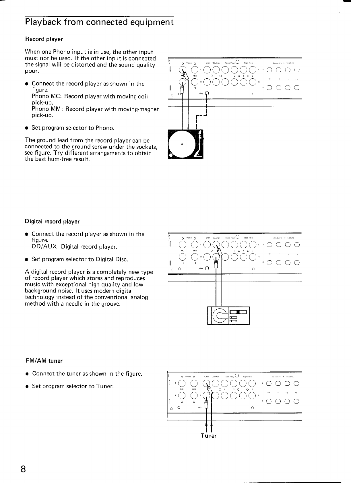
Playback from connected equipment
When one Phono input is in use, the other input
must not be used. If the other input is connected
the signal will be distorted and the sound quality
poor.
• Connect the record player as shown in the
figure.
Phono MC: Record player with moving-coil
pick-up.
Phono MM: Record player with moving-magnet
pick-up.
• Set program selector to Phono.
The ground lead from the record player can be
connected to the ground screw under the sockets,
see figure. Try different arrangements to obtain
the best hum-free result.
u
~'Q
RW
OoU
0
Phorlo
0
0'000000"
MM 00120102
0"000000"
!
0
nl.,lJ
I
r-..J
I
!
0 0 0 0
-RR
"0000
0
• Connect the record player as shown in the
figure.
DD/AUX: Digital record player.
A digital record player is a completely new type
of record player which stores and reproduces
music with exceptional high quality and low
background noise. It uses modern digital
technology instead of the conventional analog
method with a needle in the groove.
u
0
P~D"O
0
~,0
O,QOOOOO,'
Me MM 0120'02
RO ORC)
o
0
0000"
0 000
-RR
cO000

• Connect tape recorder(s) as shown in the
figu reo
• Set program selector to Tape 1 or Tape 2.
Tape 1: Playback from Tape Play 1 sockets.
Tape 2: Playback from Tape Play 2 sockets.
• Connect the equipment as shown in the figure.
• Set program selector to Digital Disc.
LINE
OUT
LINE
IN
0000"'0000
2 0 1 0 2'
OOOR
LINE LINE
IN OUT
'RR
eO
0 0 0
Recording on a connected
open-reel/cassette recorder
• Connect the program from the program source
to the corresponding input on the TIA 3012
and set the record selector to the correct
position.
The program is now connected to all Tape Rec.
sockets.
If the connected tape recorder has a B-test facility
(tape test) and it is set to carry out the B-test, the
test can be performed by setting the program
selector to respectively Tape 1 or Tape 2.
LINE
OUT
LINE
IN
LINE
IN
LINE
OUT
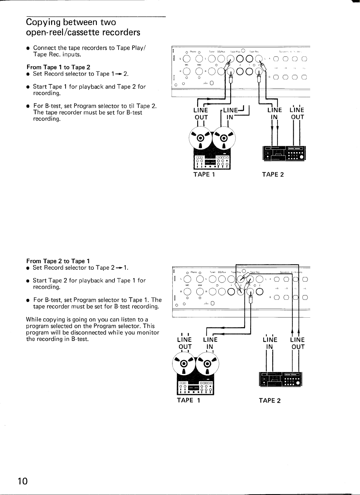
Copying between two
open- reel/cassette recorders
• Connect the tape recorders to Tape Play/
Tape Rec. inputs.
From Tape 1 to Tape 2
• Set Record selector to Tape
• Start Tape 1 for playback and Tape 2 for
recording.
• For 8-test, set Program selector to til Tape 2.
The tape recorder must be set for 8-test
recording.
1-
2.
o
0
PhorlO
0
~,0 0,00
Me MM
RO ORO
TAPE
0
1
00
OOG)
L1NE..J
IN
2 ,02
I
·R·R
80000
LINE LINE
IN OUT
t t
I~
TAPE 2
' I
From Tape 2 to Tape 1
• Set Record selector to Tape 2
• Start Tape 2 for playback and Tape 1 for
recording.
• For 8-test, set Program selector to Tape 1. The
tape recorder must be set for 8-test recording.
While copying is going on you can listen to a
program selected on the Program selector. Th is
program will be disconnected while you monitor
the recording in 8-test.
-1.
0
o
Phono
0
~
'0 0'000
Me MM
RO OROOO
0 0
o
I I
LINE
OUT
0
""0
LINE
I
IN
I
,
0
0 0
0
0
, ,
LINE
IN
LINE
OUT

Combined recording/playback
Recording Tape 1/playback Tape 2
• Set the desired program on the Program
selector.
• Make Tape 1 ready for recording.
Whilst recording takes place on Tape 1 you can
listen to another program from Tape 2.
• Set Program selector to Tape 2.
B-test on recording: Set Program selector to
Tape 1. The program played back from Tape 2
will now be disconnected.
o
0
Phone
~,0
OLOO
Me MM
RO ORO
o
0
0
0
LINE
IN
Recording Tape 2/playback Tape 1
• Select the desired program on the Program
selector.
Whilst recording takes place on Tape 2 you can
listen to another program from Tape 1.
B-test on recording: Set Program selector to
Tape 2. The program played back from Tape 1
will now be disconnected.
LINE
OUT
LINE
IN
LINE
IN
LINE
OUT
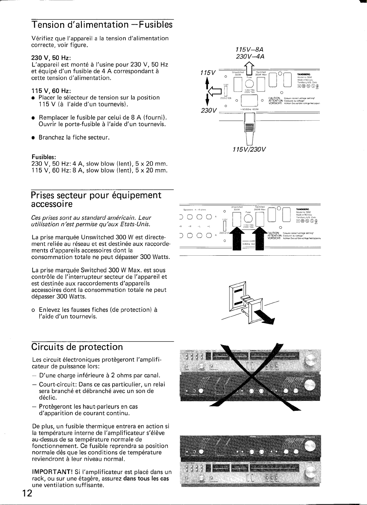
Verifiez que I'appareil a la tension d'alimentation
correcte, voir figure.
230 V, 50 Hz:
L'appareil est monteaI'usine pour 230 V, 50 Hz
et equipe d'un fusible de 4 A correspondant
cette tension d'alimentation.
a
115 V, 60 Hz:
• Placer Ie selecteur de tension sur la position
115 V (a I'aide d'un tournevis).
• Remplacer Ie fusible par celui de 8 A (fournil.
Ouvrir Ie porte-fusible
Fusibles:
230 V, 50 Hz: 4 A, slow blow (lent), 5 x 20 mm.
115 V, 60 Hz: 8 A, slow blow (lent), 5 x 20 mm.
a
I'aide d'un tournevis.
Prises s~cteur pour equipement
accessolre
Ces prises sont au standard americain. Leur
utilisation n'est permise qu'aux Etats-Unis.
La prise marquee Unswitched 300 West directe-
ment reliee au reseau et est destinee aux raccorde-
ments d'appareils accessoires dont la
consommation totale ne peut depasser 300 Watts.
La prise marquee Switched 300 W Max. est sous
contrale de I'interrupteur secteur de I'appareil et
est destinee aux raccordements d'appareils
accessoires dont la consommation totale ne peut
depasser 300 Watts.
o Enlevez les fausses fiches (de protection)
I'aide d'un tournevis.
a
Circuits de protection
Les circuit electroniques protegeront I'amplifi-
cateur de puissance lors:
- D'une charge inferieurea2 ohms par canal.
- Court-circuit: Dans ce cas particulier, un relai
sera branche et debranche avec un son de
declic.
- Protegeront les haut-parleurs en cas
d'apparition de courant continuo
De plus, un fusible thermique entrera en action si
la temperature interne de I'amplificateur s'eleve
au-dessus de sa temperature norma Ie de
fonctionnement. Ce fusible reprendra sa position
norma Ie des que les conditions de temperature
reviendront
IMPORTANT! Si I'amplificateur est place dans un
rack, ou sur une etagere, assurez dans tous les cas
une ventilation suffisante.
a
leur niveau normal.
12
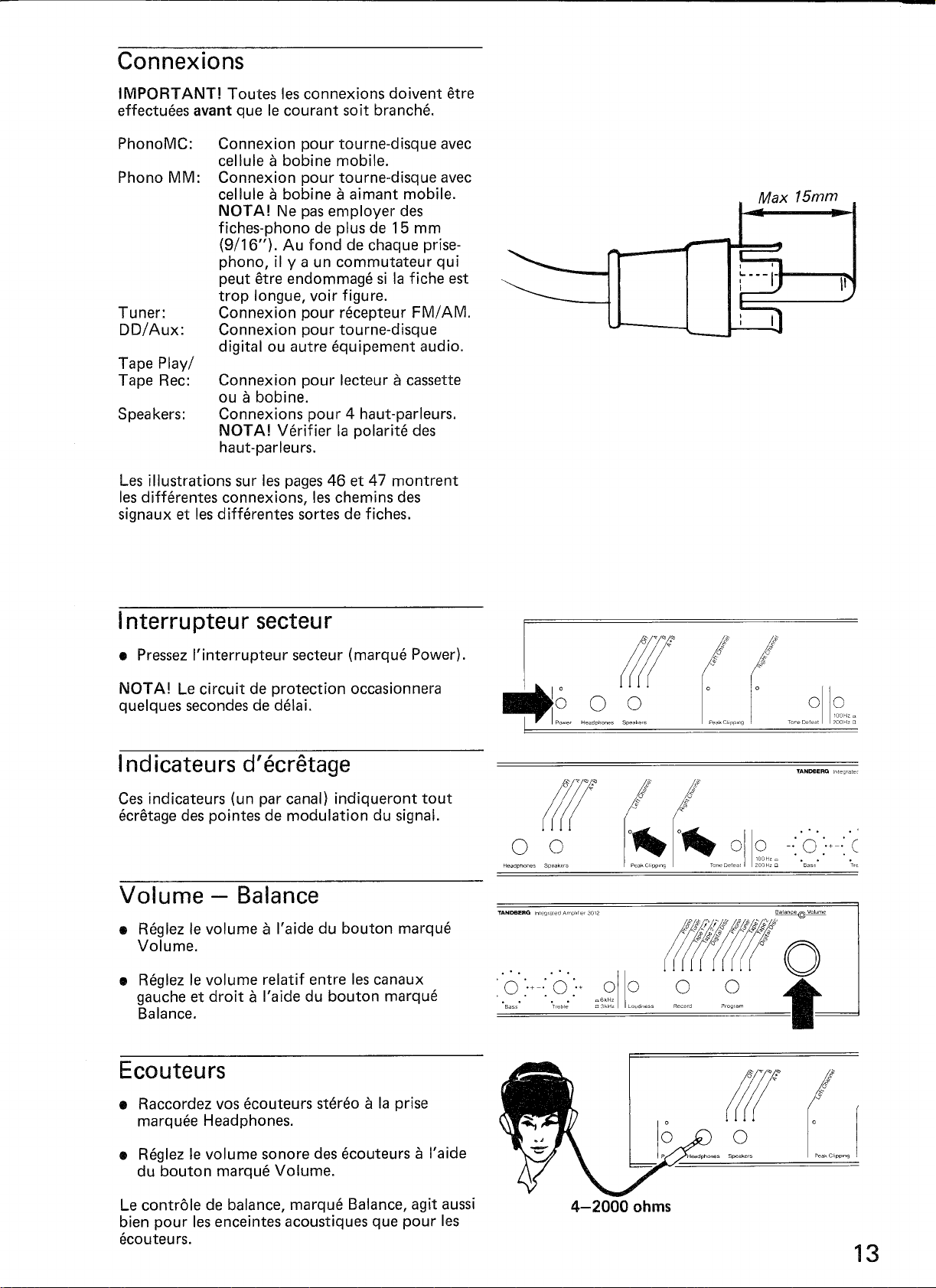
IMPORTANT! Toutes les connexions doivent etre
effectuees avant que Ie courant soit branche.
Connexion pour tourne-disque avec
celluleabobine mobile.
Connexion pour tourne-disque avec
celluleabobineaaimant mobile.
NOTA! Ne pas employer des
fiches-phono de plus de 15 mm
(9/16"). Au fond de chaque prise-
phono, il ya un commutateur qui
peut etre endommage si la fiche est
trop longue, voir figure.
Tuner:
DD/Aux:
Tape Play/
Tape Rec:
Les illustrations sur les pages 46 et 47 montrent
les differentes connexions, les chemins des
signaux et les differentes sortes de fiches.
Connexion pour nkepteur FM/AM.
Connexion pour tourne-disque
digital ou autre equipement audio.
Connexion pour lecteuracassette
ouabobine.
Connexions pour 4 haut-parleurs.
NOTA! Verifier la polarite des
haut-parleurs.
Interrupteur secteur
NOTA! Le circuit de protection occasionnera
quelques secondes de delai.
Indicateurs d'ecretage
Ces indicateurs (un par canal) indiqueront tout
ecretage des pointes de modulation du signal.
• Reglez Ie volumeaI'aide du bouton marque
Volume.
• Reglez Ie volume relatif entre les canaux
gauche et droitaI'aide du bouton marque
Balance.
0110
",6kHz
o3kHz Loudrless
• Raccordez vos ecouteurs stereoala prise
marquee Headphones.
• Reglez Ie volume sonore des ecouteursaI'aide
du bouton marque Volume.
Le contra Ie de balance, marque Balance, agit aussi
bien pour les enceintes acoustiques que pour les
ecouteurs.

Selecteur de haut-parleurs
Les boutons indiques Speakers permettent Ie
choix des 4 positions suivantes:
Off:
A:
B:
Tous les haut-parleurs sont
debranches.
Reproduction uniquement par les
deux enceintes acoustiques A.
Reproduction seulement par les
deux enceintes acoustiques B.
Reproduction par les quatre
enceintes acoustiques A et B.
ll
o@(lil(<e
0
0
1
Power Headphones Speakers Peak ChpPIIlQ Tone081('(11 200Hz 0 •E
0
I
011:?H'~ -.: (
Selecteur de programme
Le selecteur de programme, marque Program,
offre Ie choix de 5 sources de programme.
Phono:
Tuner:
Tape 1:
Tape 2:
Tourne-d isque.
Recepteur FMI AM.
Magnetophones a bobines ou a
cassette.
Magnetophones abobines ou a
cassette.
Tourne-disque digital, ou autre
equipement audio branch€! aux
prises
DDI
Aux.
0
Bil55 Treble D3kHz Loudness Record P
=6211
========f
Selecteur d'enregistrement
Le selecteur d'enregistrement, marque Record,
offre Ie choix de 5 differentes sources de
programmeaenregistrer, independamment du
programme que !'on ecoute.
Phono:
Tuner:
Tape
1-2:
Digital Disc:
Tourne-disque.
Recepteur FM/AM.
Lecture de la bande 1, enregistre-
ment sur bande 2 (copie).
Lecture de la bande 2, enregistre-
ment sur bande 1 (copie).
Tourne-disque digital.
14
0
Bass Treble D3kHz Loudness Record
=6211
--I

Grave et aigu
• Le grave et I'aigu se reglent avec les controles
marques Bass et Treble.
NOTA!
lorsque Ie bouton Tone Defeat est sorti.
Les controles ne fonctionnent que
Loudness (correcteur
physiologique de volume)
A bas volume, I'oreille perd sa sensibilite aux
gravesj.IPour compenser ce manque de
sensibilite, poussez Ie bouton Loudness. Ce
faisant, les graves seront rendus plus
forts que les autres tonalites'.
L'efficacite de Loudness depend de la position du
bouton de Volume. Les courbes du graphique
(voir page 39) montrent I'effet du Loudness pour
differentes positions du bouton de volume.
• Lorsque Ie bouton Tone Defeat est presser on
obtient une reponse en frequence lineaire
quelle que soit la position des controles de
tonalite.
NOTA!
volume) n'est pas affecte par la position du
bouton Tone Defeat.
Le Loudness (correcteur physiologique de
( ( oilS?" ··.0.·.0 .·gllo
==1 P=Cilk=U'=PPIn=9=====,,,=cDe=fe,,=,,=,=oCH=,o_f f=. =O=3kH=,==lOU=dP'="==
.:'0'
>-.:
0
:'+ 0110
~6<'"
:::='_B'='_"==-==-==-='_'P="_"=_=_=_o='_'="f
f
{""jig" ..•.~.•.•;::•.,
m
p_cog_co
__ ---
~-,~
Normalement Ie controle Bass (grave) regie les
frequences jusqu'a 200 Hz.
• Lorsque Ie bouton 100Hz/200Hz est pousse, Ie
controle Bass n'affecte que les frequences
jusqu'a 100 Hz.
Cette fonction offre une meilleure possibilite de
compenser la reduction dans les frequences basses
dans les haut-parleurs. En outre elle reduit aussi la
reaction acoustique dans la piece.
Le controle Treble (aigu) est actif a partir de
3 kHz.
• Lorsque Ie bouton 6kHz/3kHz est pousse, Ie
controle Treble commence a fonctionner a
6 kHz.
Cela donne une meilleure possibilite pour
compenser la reduction de reponse dans les
frequences aigues dans les haut-parleurs ainsi que
dans la piece.

On ne peut pas brancher deux tourne-disques
fois. Si on a branche deux tourne-disques, Ie son
sera deforme et la qualite du son pauvre.
• Raccordez Ie tourne-disque comme indique.
Phono
a
Phono MM: Tourne-disque equipe d'une cellule
a
• Tourner Ie selecteur de programmeala
position Phono.
Le cable terre du tourne-disque peut etre raccorde
a
la vis de terre (ground) en dessous des prises
(voir figure). Essayez divers cablages pour obtenir
Ie meilleur resultat, c'estadire Ie moins de
ronflement possible .
Me:
Tourne-disque equipe d'une cellule
bobine mobile.
aimant mobile.
a
la
~ 0
Phona
0
~'Q
o
0,000000,'
MM
00'
RW6OROOOOOOR
o
0 ~
r-..I
I
r
I
20102
0
~R
AO
0
!
• Tourner Ie selecteur de programmeala
position Digital Disc.
Un tourne-disque digital est un nouveau modele
de tourne-disque qui utilise une nouvelle
technologie d'enregistrement et de reproduction
de musique, d'une tres grande qualite.
• Tourner Ie selecteur de programmeala
position Tuner.
,0
O,QOOOOO,
Me MM 0120102
RO ORO
o
0
0000"
A
0 0 0 0
·n
80000
 Loading...