

Page 1

資料番号 W301-0411E
01
Load Moment Indicator
Model
AML-C
Page 2

Foreword
Foreword
This service manual (this document) is compiled to
provide information on the AML-C that is equipped on
the crane.
"Input/Output Signals of the AML System" in this
document offers the general description on the
electrical circuit of the crane. For the detailed electrical
circuit, refer to the service manual (Circuit diagrams
and Data) of each model.
For the actual works, perform appropriate repair and
service with referring to the separate operation and
maintenance manual, parts catalog, and service
manual of the applicable model.
When part replacement is needed, refer to the parts
catalog first to check the disassembly unit as well as
the parts sales unit.
1. Applicable Crane Model / Spec. No.
Crane model
GR-1000XL-2
Spec. No. GR-1000-2-00101
GR-1000-2-00103
GR-750XL-2
Spec. No. GR-750-2-00101
With the crane models not shown in the above table,
refer to this service manual when the document
number of this manual is noted in the service manual
for each model.
Figures and contents in this manual are subject to
change depending on improvements, etc.
i
W301-0411E
Page 3

Foreword
2. Table of Contents
Foreword
1. Applicable Crane Model / Spec. No................... i
2. Table of Contents...............................................ii
3. Acronyms and Abbreviations............................iv
4. International Standard ...................................... v
5.Crane Performance ......................................... vii
6.Reduction of Rated Capacity.......................... viii
Chapter A
(Component of AML System)
A-1 Components of the AML System ............... 1
A-2 Input/Output Signals
of the AML System ....................... 11
2.1 AML Control Unit (Pin Assignment)
CN1 – CN9
B-6 Do Output Control.................................... 59
6.1 Cause for AML Automatic Stop
Output .......................................... 59
6.2 Do Output Abnormality Processing.... 64
6.3 Drum Indicator Control Function........ 65
6.4 Output of warning .............................. 66
B-7 AML Control............................................. 67
7.1 Backward Stability Stop Function ...... 67
7.2 Working Range Limit Stop Function .. 67
7.3 Output of Interference Prevention
Warning .................................. 70
7.4 Winch Drum Position Selection
Function ....................................... 71
B-8 Proportional Control Function.................. 75
B-9 AML Cancel Function .............................. 76
Chapter C
(Maintenance Mode)
Chapter B
(User Mode)
B-1 Functions and How to use
the User Mode.............................. 26
B-2 Registration of Operating State and AML
Function Check ............................ 28
B-3 Alarm and Recovery Operation ............... 38
3.1 Type of Warning Codes and Buzzer .. 38
3.2 Warning Code and Crane Model
Comparison Table ........................ 39
3.3 Warning code and Remedy List......... 40
B-4 Other Functions ....................................... 43
4.1 Working Range Limit Function........... 43
4.2 TARE Function................................... 49
4.3 Mute Alarm Function .......................... 49
4.4 Fuel Consumption Indicator............... 50
4.5 User Adjustment Menu ...................... 51
Outline of Maintenance Mode......................... 80
C-1 Operation Keys and Menu ....................... 81
C-2 Individual Main Menu Functions .............. 85
C-3 Integrated Information Display Screen ...117
C-4 Error Code............................................. 122
4.1 Classification of Error Code ....................122
4.2 Error History............................................122
4.3 Error Notification .....................................123
4.4 Error Code Table.....................................124
4.5 CPU State Indicator LED ........................133
C-5 Required Adjustment after AML System
Part Replacement ...................... 134
C-6 Disassembly and Assembly................... 135
B-5 Action against AML System Error ............ 58
ii
W301-0411E
Page 4

Foreword
Chapter D
(Adjustment Mode)
Outline of Adjustment Mode.......................... 150
D-1 Operation Keys and Menu ..................... 151
D-2 Detector Adjustment .............................. 156
D-3 Valve Adjustment ................................... 166
3.1 Adjustment Sub Menu ............................ 166
3.2 Swing Output Adjustment
(Offset Method) ................................ 167
3.3 Swing Output Adjustment
(Characteristics Measurement Method) ....... 168
3.4 Elevating / Telescoping
Output Adjustment............................ 170
3.5 Function of Slow Stop............................. 171
Chapter E
(Information and Data)
E-1 AML Adjustment Value List.................... 180
E-2 Detector Check...................................... 184
E-3 AML Control Function List ..................... 190
E-4 AML Input/Output List............................ 192
A
B
C
D
E
D-4 Performance Setup................................ 172
D-5 Operation History Erase ........................ 174
D-6 Option Select ......................................... 175
D-7 AML Emergency / Override Switch
History Erase.............................. 178
D-8 Outrigger Emergency Setting
History Erase.............................. 179
iii
W301-0411E
Page 5

Foreword
3. Acronyms and Abbreviations
The following list contains some of the acronyms and
abbreviations used in this manual.
AML: Load Moment Indicator
AML override: Refer to Chapter B-9
Actuator: A mechanical device which converts
supplied energy into mechanical work
(Ex. hydraulic motor, hydraulic cylinder)
Ai: Analog Input
A/D conversion: Analog/Digital conversion
Ao: Analog Output
Aux.: Auxiliary
ASME: American Society of Mechanical Engineers
CAN: Controller Area Network (SAE1939)
CHG: Charge
CPU: Central Processing Unit
C/W: Counter weight
D/A: Digital/ Analog conversion
DCU: Display Control Unit (Meter controller)
Di: Digital Input
Do: Digital Output
Eco mode: Environmental communication mode
ECU: Engine Control Unit
FET: Field-effect Transistor
F.B.: Feed back
Fig.: Figure
Flash memory:
A Semiconductor memory device which can
be electrically erased and rewritten.
FMI: Failure Mode Identifier
FLJ: Full auto Luffing Jib
F/J: Front Jack
F/R: Front Right
F/L: Front Left
ICF: Information Controller for Telematics
ID: Identification
ISO: International Organization for Standardization
J/S: Joystick
LCD: Liquid Crystal Display
LED: Light Emitting Diode
MDT: Multiplex Data Transmitter
MMT: Moment
OE: Output Enable signal
(Fail-safe is active when the signal is ON.)
O/R: Outrigger
PC: Personal Computer
Pi: Pulse input
Pin Assignment:
Assignment of signals to the pins of
connectors
PT: Power Tilt
PTO: Power Take-off
RAM: Random Access Memory
ROM: Read Only Memory
rpm: Revolution per minute
RY: Relay
R/J: Rear Jack
SAE: Society of Automotive Engineers
Si: Serial input
SOL: Solenoid
SPN: Suspect Parameter Number
(Data Classification Number)
STM: Signal Transmitter (D, E type)
SW: Switch
S/T: Single Top
Tr: Transistor
T/C: Torque Converter
T/M: Transmission
USB: Universal Serial Bus
VCU: Vehicle Control Unit (node)
WDT: Watched dog timer
3S: 3 Second
20ms: 20 millisecond (20/1000 second)
Rated capacity = Max. Hoist medium load
Hoist medium load = _Net load + Hook Assy
_Net load = Payload + Sling
iv
W301-0411E
Page 6
Foreword
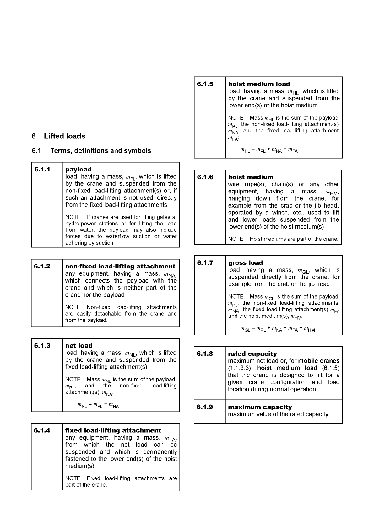
4. International Standard
ISO 4306-1
(Only description in English is shown here.)
Cranes – Vocabulary - Part 1: General
Fourth edition 2007.10.15
v
W301-0411E
Page 7

Foreword
(Only description in English is shown here.)
m
Hoist medium
Fixed load-lifting attachment(s)
Non-fixed load-lifting
attachment(s)
HM
Hoist rope hanging down from jib head Hoist rope hanging down from crab
m
FA
Hook assembly Hook assembly Bottom block Bottom block Bottom block
m
NA
Skip and chain Net Rope slings
Electromagnet
and chain
Grab
m
Net load + Hook
Hoist medium load =
Gross load
GL mHL mNL
Net load =
Payload + Slings
Payload
PL
Contents of
skip
Contents of net
m
Box and
contents
Scrap iron
Contents of
grab
Table 1
vi
W301-0411E
Page 8

5. Crane Performance
Foreword
vii
W301-0411E
Page 9

Foreword
6. Reduction of Rated Capacity
Boom Lift
The rated capacities for boom lift assume that the jib is stowed in the specified position and the main winch is
used. When the jib is attached to the boom end during boom lift, subtract the value in the table below from the
rated capacity.
Single Top Lift and Jib Lift
The rated capacities for single top lift or jib lift assume that the main winch is used. If you perform single top lift
or jib lift using the auxiliary winch, subtract the mass of the main hook block from the rated lifting capacity
values.
(ex. : GR-750XL-2)
1
343-979-01200
343-979-01190
△
△
1
viii
W301-0411E
Page 10

A
Chapter A
Components of AML System
Contents
A-1 Components of the AML System.... 1
1.1 System configuration ................................. 1
1.1.1 Diagram of the Main System ...................... 1
1.1.2 AML-C Block diagram.............................. 2
1.2 Display Unit................................................ 3
1.2.1 Display panel.............................................. 4
1.2.2 LED Display................................................ 6
1.2.3 Control switches......................................... 7
1.3 AML Main Unit ........................................... 8
1.3.1 Construction ............................................... 8
1.3.2 Panel outside view (CN1 – CN9)................ 9
1.3.3 Boards and Inner connectors ................... 10
A-2 Input/Output Signals of the
AML System ...........................11
2.1 AML Control Unit (Pin Assignment) ..........11
2.1.1 CN1 Connector (8-Pin) ............................. 11
2.1.2 CN2-1 Connector (20-Pin) ........................12
2.1.3 CN2-2 Connector (16-Pin) ........................14
2.1.4 CN3 Connector (12-Pin) ...........................16
2.1.5 CN4 Connector (6-Pin) .............................17
2.1.6 CN5 Connector (16-Pin) ...........................18
2.1.7 CN6 Connector (14-Pin) ...........................22
2.1.8 CN7 Connector (20-Pin) ...........................23
2.1.9 CN8 Connector (8-Pin) .............................24
2.1.10 CN9 (USB) Connector (4-Pin)................25
2.1.11 Explanation of the Signals (Di, Do) ........25
i
Page 11

Chapter A Chapter A
Components of AML System
A-1 Components of the AML System
1.1 System configuration
1.1.1 Diagram of the Main System
(Overwind detector)
(Overwind)
1. Load
2. Anti-twoblock (overwind) stop
3. Backward stability stop:
4. Working range limit stop:
moment ratio ≥ 100%
AML vent / compulsory unload of the main relief valve.
٠If an overload occurs, the AML stops the 24-V output from Do1. Thus the solenoid valve for VENT is
returned to neutral by the spring and vents the oil in the spring side of the balance piston in the main-circuit
safety valve into the tank circuit. The whole oil discharged by the pump is unloaded into the tank, making
crane operation toward critical sides impossible.
٠When crane operation toward non-critical sides (hoisting down, boom raising, boom retraction) is detected,
no oil is vented from the safety valve into the tank. Thus the crane operation becomes available.
:
If operation toward critical sides (hoisting up, boom lowering, boom extension) is attempted while the hook
block is over wound, 24-V output from Do1 stops. Thus the crane operation toward critical sides becomes
impossible due to AML vent (compulsory unload) in the same way as overload.
When operation toward non-critical sides is detected, the operation becomes available.
When the boom is raised over the specified angle, the output from Do1 stops and the crane operation stops
automatically due to AML vent. Recovery from the automatic stop is possible only by boom raising.
When the boom head approaches a pre-registered limit of the working range, slow stop function works and
the AML energizes the corresponding proportional solenoid valve. It slowly closes the pilot pressure circuit
for the main control valve to decelerate crane operation until the main control valve becomes neutral and
the output from Do1 stops to make AML vent disable crane operation. For swing limit, however, the
proportional solenoid valve makes the main control valve immediately to stop the crane. In this case the
crane does not swing beyond the limit even if the AML override is activated, and it swings only toward within
of the limit.
1
W301-0411E
Page 12

Chapter A Chapter A
Components of AML System
1.1.2 AML-C Block diagram
1. While the PTO switch is ON, AML-C and DCU give and take the data on the version No. of the DCU and error
occurring in the DCU.
For details of the data, refer to the "N-1 DCU" section in the service manual for the corresponding model.
2. The signal transmitter (STM-E) is common to all GR model.
For details of the data, refer to the "N-1 STM-E" section in the service manual for the corresponding model.
3. Communication between STM-E and ECU on the machine with Mitsubishi engine (GR-750XL-2,
GR-1000XL-2) is sent via K-LINE.
2
W301-0411E
Page 13

Chapter A Chapter A
Components of AML System
1.2 Display Unit
Composition of the display Unit
1. The LED display indicates the limit state of each working range, rotation state of the winch drum, and AML
control state. The display panel indicates the moment ratio, crane state, outrigger state, swing position, and
error code.
(LCD)
2. AML startup
When the PTO switch is set to "ON," the AML starts.
3
W301-0411E
Page 14

E
Chapter A Chapter A
Components of AML System
1.2.1 Display panel
NOTIC
• Load moment ratio is not a ratio of the
hoist medium load to the rated capacity.
Find the correct hoist medium load from
the rated capacity.
• The AML is not a hoist medium load
indicator. The hoist medium load
indication is a reference value, and not a
correct mass of the lifted load.
(1) Load moment ratio display
Shows the load moment ratio with a bar graph.
(2) Load moment ratio index
Serves as an index how critical the load moment ratio is by the bar graph; safe (green), warning (yellow),
orcritical (red).
(3) Jib lift indicator symbol
Appears when the jib lift is registered.
Flashes when the jib set state is registered to the load moment indicator.
4
W301-0411E
Page 15

Chapter A Chapter A
(4) Single top lift indicator symbol
Appears when the single top lift is registered.
(5) Counterweight indicator
Indicates the state of the mounted counterweight.
(6) Crane status indicator (A-1) Boom telescope
(7) Crane status indicator (A-2
(8) Crane status indicator (A-3) Jib dismount
(9) Crane status indicator (A-4) Winch selection
(10) Crane status indicator (B-1) Boom telescoping or Auxiliary winch Control
(11) Crane status indicator (B-2)
The indicator (icon) shows a crane state.
Refer to "Operation Indicator Display" (Chapter B-1) for the meaning of the icons.
(12) Swing position display
Shows the current swing position.
The display is graduated in 45°.
Components of AML System
) Jib lock
Hydraulic oil temperature, Outrigger switch out of neutral or Outrigger state emergency registration
(13) Front position symbol
Appears when the boom is directed to the front of the vehicle.
(14) On-rubber status indicator symbol
Flashes during on-rubber creep operation, and turns on steadily during on-rubber stationary operation.
(15) Outrigger status indicator symbol
Indicates the extension width of outriggers.
The outer frames of the symbol represent the maximum available steps of the outrigger extension, and the
inner frames (black-filled segments) represent the current step of outrigger extension.
(16) Boom Lift Indicator Symbol
Appears when the boom lift is registered to the AML.
(17) Fuel consumption indicator
The fuel consumption rate during crane operation is indicated.
(18) Eco mode indicator
Lights up when Eco mode switch is on and displays current mode such as Eco mode 1 or Eco mode 2.
5
W301-0411E
Page 16

Chapter A Chapter A
Components of AML System
1.2.2 LED Display
6
W301-0411E
Page 17

Chapter A Chapter A
Components of AML System
1.2.3 Control switches
Table 1.2.3
No. Name Description
0 Preset menu key Used for go to the preset menu.
1 F1 key Used to select the function shown as “F1” in the pop-up window.
2 F2 key Used to select the function shown as “F2” in the pop-up window.
3 F3 key Used to select the function shown as “F3” in the pop-up window.
4 F4 key Used to select the function shown as “F4” in the pop-up window.
5 Working range limit key Used to register/cancel the working range limit.
6 Counterweight set key Used to select the mass of the mounted counterweight on AML.
7 Rope part line key Used to select the number of part lines on AML.
8 Lift state select key
9 Outrigger state select key Used to select the outrigger extension width on AML.
Used to select the lift state (boom, jib in various length and offset angle)
on AML.
10 Exit key Used to close the pop-up window.
11 Display change key Used to change the display content.
12 Set key Used to confirm (register) the selected state.
13 Check key Used during pre-operational inspection.
7
W301-0411E
Page 18

Chapter A Chapter A
Components of AML System
1.3 AML Main Unit
1.3.1 Construction
1. Case assembly
2. Case assembly
3. Bracket
4. Case 1
5. Dustproof sponge assembly
6. CON1 board
LED (3 pcs)
7. CON2 circuit board
8. Case 2
9. Display board
10. CPU board
11. Surface sheet assembly
8
W301-0411E
Page 19

Chapter A Chapter A
Components of AML System
1.3.2 Panel outside view (CN1 – CN9)
Front
Rear
0
361-933-41030
9
W301-0411E
△
Page 20

Chapter A Chapter A
Components of AML System
1.3.3 Boards and Inner connectors
Jumper lead
CON2 board
CON1 board
CON1 + CON2 boards
Cable assembly for CN11
DISP board
CPU board
CPU + DISP boards
Jumper lead
LCD connection cable
Graphic liquid crystal display
(LCD)
10
W301-0411E
Page 21

Chapter A Chapter A
Components of AML System
A-2 Input/Output Signals of the AML System
2.1 AML Control Unit (Pin Assignment)
Below are the names of the signals that are input to/output from the connectors, and the descriptions of their
functions. (Refer to 1.3.2 Panel outside view, from the back)
2.1.1 CN1 Connector (8-Pin)
CN1 connector
Pin No. Name
1 MBGND Signal name: Ground Output voltage: DC 0 V
Signal names and functions
2 MBGND Signal name: Ground Output voltage: DC 0 V
3 DOPOW Signal name: Power for circuit Output voltage: DC 24 V
4 MBGND Signal name: Ground Output voltage: DC 0 V
5 MBGND Signal name: Ground Output voltage: DC 0 V
6 MBPOW Signal name: Power for AML main body Input voltage: DC 24 V
7 DOPOW Signal name: Power for circuit Output voltage: DC 24 V
8 DOPOW Signal name: Power for circuit Output voltage: DC 24 V
11
W301-0411E
Page 22

Chapter A Chapter A
Components of AML System
2.1.2 CN2-1 Connector (20-Pin)
CN2-1 connector SW status in AML
Pin No. Name
1 Di1+
2 Di2+
- Signal name: Boom telescoping / Aux. winch operation
Detects whether boom telescoping or auxiliary winch
operation is selected.
- Signal name:2nd boom section full retraction detection
Detects that 2nd boom section is fully retracted.
Signal names and functions
selection
(Data No. #---)
(#17206-21)
(#17204-11)
ON (0) OFF (1)
Aux. winch
operation
selected
Full
retraction
Boom
telescoping
selected
No full
retraction
3 Di3+
4 Di4+
5 Di5+
6 Di6+
7 Di7+
8 Di8+
9 Di9+
- Signal name:3rd—top boom section full retraction detection
Detects that 3rd, 4th and top boom sections are fully
retracted.
- Signal name: Swing free detection
Detects swing free/lock status.
- Signal name: Anti-twoblock cancel
Cancels the anti-twoblock function of the hook.
- Signal name: Anti-twoblock cancel indication
Detects the indication of anti-twoblock cancel.
- Signal name: 100% stop cancel (AML cancel)
Cancels the overload stop function.
- Signal name: 100% stop cancel indication
Detects the indication of 100% stop cancel.
- Signal name: Jib connecting (lock) pin insertion detection
Detects that the jib connecting (lock) pin is inserted when the
jib is stowed.
- Signal name: Jib extension detection
Detects the jib extension status.
- Signal name: Swing over-front detection
Detects the swing position is in over-front (within 2°
over-front).
- Signal name: Main hoist-up detection
Detects the main winch hoist-up operation.
(#17204-12)
(#17204-31)
(#17206-3)
(#17206-7)
(#17206-2)
(#17206-6)
(#17204-24)
(#17204-33)
(#17204-23)
(#17202-1)
Full
retraction
Swing free Swing lock
Stop disabled Stop enabled
Cancel
indication
Stop disabled Stop enabled
Cancel
indication
Inserted
(fixed)
Jib stowed Jib extension
Over-front
position
No operation Operation
No full
retraction
No cancel
indication
No cancel
indication
Not inserted
Other than
over-front
12
W301-0411E
Page 23

Chapter A Chapter A
CN2-1 connector SW status in AML
Pin No. Name
Components of AML System
(Data No. #---)
Signal names and functions
ON (0) OFF (1)
(#17202-2)
10 Di10+
- Signal name: Main hoist-down detection
Detects the main winch hoist-down operation.
No operation Operation
(#17202-3)
11 Di11+
- Signal name: Auxiliary hoist-up detection
Detects the auxiliary winch hoist-up operation.
No operation Operation
(#17202-4)
12 Di12+
- Signal name: Auxiliary hoist-down detection
Detects the auxiliary winch hoist-down operation.
No operation Operation
(#17202-9)
13 Di13+
- Signal name: Boom extension detection
Detects the boom extending operation.
No operation Operation
(#17202-10)
14 Di14+
- Signal name: Boom retraction detection
Detects the boom retraction operation.
No operation Operation
(#17202-11)
15 Di15+
- Signal name: Boom raising detection
Detects the boom raising operation.
No operation Operation
(#17202-12)
16 Di16+
- Signal name: Boom lowering detection
Detects the boom lowering operation.
No operation Operation
(#17202-17)
17 Di17+
- Signal name: Swing right detection
Detects the swing operation to the right.
No operation Operation
(#17202-18)
18 Di18+
19 Di19+
- Signal name: Swing left detection
Detects the swing operation to the left.
- Signal name: Outrigger emergency setting
Detects the selection of outrigger emergency setting.
(#17206-41)
No operation Operation
Normal
setting
Emergency
setting
20 Di20+ (Spare)
13
W301-0411E
Page 24

Chapter A Chapter A
Components of AML System
2.1.3 CN2-2 Connector (16-Pin)
CN2-2 connector SW status in AML
Pin No. Name
1 Di21+ (Spare)
2 Di22+
3 Di23+
- Signal name: Counterweight fitting detection
Detects fitting status of the counterweight.
- Signal name: Main over-unwind detection
Detects the over-unwinding status of the main winch drum.
Signal names and functions
(Europe spec.)
- Signal name: Aux. winch over-unwind detection
4 Di24+
Detects the over-unwinding status of the auxiliary winch
drum.
(Europe spec.)
(Data No. #---)
(#17204-3)
(#17202-37)
(#17202-38)
ON (0) OFF (1)
Mounted Not mount
Not
over-unwind
Not
over-unwind
Over-unwind
Over-unwind
5 FG Frame ground (Connected with ground on circuit board)
6 P3 (Spare)
7
8
P2A(P2)
P1A(P1)
Signal name: Drum indicator input (Aux.)
Detects the rotation of auxiliary winch drum.
Signal name: Drum indicator input (Main)
Detects the rotation of main winch drum.
(#17204-9)
9 Di25+
- Signal name: Jib removal detection
Detects removal of the jib from the crane boom.
Mounted Removed
(#17206-64)
- Signal name: Deactivation of over-unwinding cutout
10 Di26+
Deactivates stop due to over-unwinding only among the
automatic stop functions of the AML.
Over-unwinding
stop deactivated
Over-unwinding
stop activated
(Europe spec.)
11 Di27+
- Signal name:3rd—top boom section extension switch
Shifting operation of boom telescoping cylinder (from No. 1 to
No. 2)
(#17206-55)
Extension
Not
extension
14
W301-0411E
Page 25

Chapter A Chapter A
CN2-2 connector SW status in AML
Pin No. Name
12 Di28+
13 FG Frame ground (Connected with ground on circuit board)
14 PSRC (Spare)
15 P2B
16 P1B
- Signal name: Twoblocking detection
Detects the twoblocking.
Signal name: Drum indicator input (Aux.)
Detects the rotation of auxiliary winch drum.
Signal name: Drum indicator input (Main)
Detects the rotation of main winch drum.
Components of AML System
(Data No. #---)
Signal names and functions
(#17202-36)
ON (0) OFF (1)
Not
twoblocking
Twoblocking
15
W301-0411E
Page 26

Chapter A Chapter A
Components of AML System
2.1.4 CN3 Connector (12-Pin)
CN3 connector
Pin No. Name
1 +5V
2 Ai1
3 Ai2
4 Ai3
- Signal name: 5-V impressed voltage power output for detectors
Impressed voltage output to boom length detector, boom angle detector, swing angle detector
1, and swing angle detector 2
- Signal name: Boom length
Input voltage of boom length detector (DC 0 to 5 V)
- Signal name: Boom angle
Input voltage of boom angle detector (DC 0 to 5 V)
- Signal name: Swing angle detector 1
Input voltage of 2-potentiometer type swing angle detector 1 (DC 0 to 5 V)
Signal names and functions
5 AGND
6 SHIELD
7 +5V
8 Ai4
9 Ai5
10 Ai6
11 AGND
12 SHIELD
- Signal name: Analog ground
Ground for boom length detector, boom angle detector, swing angle detector 1, and swing
angle detector 2
Signal name: Shield (Connected with ground on circuit board)
Shield for boom length detector, boom angle detector, swing angle detector 1, and swing
angle detector 2
- Signal name: 5-V impressed voltage power output for detector
Impressed voltage output to elevating cylinder pressure sensor
Signal name: Swing angle detector 2
Input voltage of 2-potentiometer type swing angle detector 2 (DC 0 to 5 V)
- Signal name: Elevating cylinder extension side pressure
Detects the pressure of elevating cylinder tube side chamber (elevation raising).
Usage: Used for moment detection
- Signal name: Elevating cylinder retraction side pressure
Detects the pressure of elevating cylinder rod side chamber (elevation lowering).
Usage: Used for moment detection
- Signal name: Analog ground
Ground for elevating cylinder pressure sensor
- Signal name: Shield (Connected with ground on circuit board)
Shield for elevating cylinder pressure sensor
16
W301-0411E
Page 27

Chapter A Chapter A
Components of AML System
2.1.5 CN4 Connector (6-Pin)
CN4 connector
Pin No. Name
1 FG
2 +5V
3 Ai7
4 Ai8
5 AGND
Signal names and functions
(Spare)
Signal name: 5-V impressed voltage power for detector
Impressed voltage to main pressure detector
Signal name: Main pressure
Input voltage to main pressure detector
(Spare)
Signal name: Analog ground
Ground for main pressure detector
6 SHIELD
Signal name: Shield
Shield for main pressure detector
17
W301-0411E
Page 28

Chapter A Chapter A
Components of AML System
2.1.6 CN5 Connector (16-Pin)
CN5 connector
Pin No. Name
1 Do1+
2 Do2+
Signal names and functions
- Signal name: AML stop output (AML vent / compulsory unload)
Controls the unload solenoid valve, and performs the automatic stop output.
- Signal name: Lever non-operation output
Shifts the flow volume in the hydraulic circuit from the stand-by status to large-volume status
when a control lever is operated.
(Data No. #---)
(#17802-1)
(#17802-147)
- Signal name: Telescoping control output 1
Output of telescoping cylinder change solenoid valve
3 Do3+
The values for (A) and (B) are as follows:
Applied to special telescoping mode (Tel. mode II)
- Signal name: Telescoping control output 2
Output of No.2 telescoping cylinder retraction prevention solenoid valve
4 Do4+
(A), (B) data is/are as follows.
(#17802-142)
Output (ON) condition: (1) or (2) or (3)
(1) Boom length is (B) or more.
(2) Boom length is between (A) and (B), and the next boom section extension input is ON.
(3) Boom length is between (A) and (B), and the boom full retraction 2 detection is OFF.
Output (OFF) condition: (4) or (5)
(4) Boom length is (A) or less.
(5) Boom length is between (A) and (B), and the boom full retraction 2 detection is ON.
GR-750XL-2 : (A) 18.60m, (B):19.40m - for tel. mode I (#20586)
GR-1000XL-2 : (A) 20.35m, (B):21.15m - for tel. mode I
(#17802-143)
Output (ON) condition: (1) or (2)
(1) Boom length is(B) or more.
(2) Boom length is between (A) and (B), and the extension input of next boom section is
ON.
Output (OFF) condition: (3) or (4)
(3) Boom length is (A) or less.
(4) Boom length is between (A) and (B), and
the boom full retraction 2 detection is ON and the next boom section extension input is
OFF.
GR-750XL-2 : (A) 34.60m, (B) :35.40m (
#20584)
GR-1000XL-2 : (A)37.85m, (B) : 38.65m
18
W301-0411E
Page 29

Chapter A Chapter A
CN5 connector
Pin No. Name
5 Do5+
6 Do6+
- Signal name: Tactile type drum indicator (Main)
Interlocked with the drum indicator LED, output is performed to the tactile type drum indicator.
- Signal name: Tactile type drum indicator (Aux.)
Interlocked with the drum indicator LED, output is performed to the tactile type drum indicator.
Components of AML System
(Data No. #---)
Signal names and functions
(#17802-122)
(#17802-123)
(#17802-132)
7 Do7+
8 Do8+
9 Do9- (Spare)
- Signal name: Jib set output
Improves the winch capacity when in the jib set status.
(#17802-124)
-Signal name: AML normal output (Normal: 24V output, Abnormal: 0V)
Detects the reckless driving of task, and outputs the result.
[GR-1000XL-2]
- Signal name: Main winch high-speed hoist-down
10 Do10-
11 D o 11 -
12 Do12-
Output to drive the high-speed hoist-down valve of main winch
(Spare) [GR-750XL-2]
[GR-1000XL-2]
- Signal name: Auxiliary winch high-speed hoist-down
Output to drive the high-speed hoist-down valve of auxiliary winch
(Spare) [GR-750XL-2]
- Signal name: Buzzer output (AML warning)
Controls the external buzzer depending on the load moment ratio.
There are two outputs: intermittent output for when notice is made and continuous output for
when limit is reached.
Output when condition(s) is/are met: OFF output
(#17802-148)
(#17802-149)
(#17802-12)
Output condition: Load moment ratio of 90% or more and less than 100%; intermittent
output with 0.8 s interval
Load moment ratio of 100% or more: Continuous output
13 Do13-
- Signal name: Buzzer output (twoblocking warning)
Twoblocking warning buzzer sounds when the twoblocking status is reached.
Output when in twoblocking status: ON output
19
W301-0411E
(#17802-38)
Page 30

Chapter A Chapter A
CN5 connector
Pin No. Name
Components of AML System
(Data No. #---)
Signal names and functions
(#17802-9)
- Signal name: External indicator lamp (up to 90%, green)
When the moment load factor is less than 90%, the green external indicator lamp lights.
Output condition:
(1) and (2) and (3)
(1): Load moment ratio is less than 90%.
(2): 100% cancel indication (Di6) is "Not canceled" status.
(3): Twoblocking cancel indication (Di5) is "Not canceled" status.
When in the boom operation with jib elected
(during main operation with jib elected), the green
external indicator lamp lights when the load
moment ratio described below is reached.
14 Do14-
Output when condition is met: OFF output
Outrigger
extension
width
Maximum
extension
Middle
extension 2
Middle
extension 1
Output
GR-750XL-2 GR-1000XL-2
Less than 78% Less than 84%
Less than 77% Less than 83%
Less than 70% Less than 82%
(#20803)
- Signal name: External indicator lamp (90% to 100%, yellow)
When the moment load factor is 90% or more and less than 100%, the yellow external
indicator lamp lights.
Output condition:
When in the boom operation with jib
(during main operation with jib
yellow external indicator lamp lights when the
load moment ratio described below is reached.
15 Do15-
Output when condition is met: OFF output
(1) and (2) and (3)
(1): Load moment ratio is 90% or more and 100% or less.
(2) 100% cancel indication (Di6) is "Not canceled" status.
(3): Twoblocking cancel indication (Di5) is "Not canceled" status.
elected
elected), the
Outrigger
extension
width
Maximum
extension
Middle
extension 2
Middle
extension 1
GR-750XL-2 GR-1000XL-2
78% or more
Less than 88%
77% or more
Less than 87%
70% or more
Less than 80%
Output
(#17802-10)
(#20803)
84% or more
Less than 94%
83% or more
Less than 93%
82% or more
Less than 92%
20
W301-0411E
Page 31

Chapter A Chapter A
CN5 connector
Pin No. Name
Components of AML System
(Data No. #---)
Signal names and functions
(#17802-11)
- Signal name: External indicator lamp (100% or more, red)
When the load moment ratio is 100% or more, the red external indicator lamp lights.
Output condition:
When in the boom operation with jib
(during main operation with jib elected), the
red external indicator lamp lights when the
load moment ratio described below is
16 Do16-
reached.
Output when condition is met: OFF output
(1) or (2) or (3)
(1): Load factor exceeds 100%.
(2) 100% cancel indication (Di6) is "Canceled" status.
(3): Twoblocking cancel indication (Di5) is "Canceled" status.
Outrigger
extension
width
Maximum
extension
Middle
extension 2
Middle
extension 1
elected
(#20803)
Output
GR-750XL-2 GR-1000XL-2
88% or more 94% or more
87% or more 93% or more
80% or more 92% or more
21
W301-0411E
Page 32

Chapter A Chapter A
Components of AML System
2.1.7 CN6 Connector (14-Pin)
CN6 connector
Pin No. Name
1 Ao1+
2 Ao1-
3 Ao2+
4 Ao2-
Signal names and functions
- Signal name: Swing right proportional solenoid valve
Drives the proportional reducing valve for right swing.
- Signal name: Swing right proportional solenoid valve COM
(Output return terminal)
- Signal name: Swing left proportional solenoid valve
Drives the proportional reducing valve for left swing.
- Signal name: Swing left proportional solenoid valve COM
(Output return terminal)
(Data No. #---)
(
#17804-1)
(
#17804-2)
5 Ao3+
6 Ao3-
7 FG
8 Ao4+
9 Ao4-
10 Ao5+
11 Ao5-
12 AO6+
- Signal name: Boom raising proportional solenoid valve
Drives the proportional reducing valve for boom raising.
- Signal name: Boom raising proportional solenoid valve COM
(Output return terminal)
Frame ground
- Signal name: Boom lowering proportional solenoid valve
Drives the proportional reducing valve for boom lowering.
- Signal name: Boom lowering proportional solenoid valve COM
(Output return terminal)
- Signal name: Swing relief proportional solenoid valve
Drives the proportional reducing valve for swing relief.
- Signal name: Swing relief proportional solenoid valve COM
(Output return terminal)
(Spare)
(
#17804-9)
(
#17804-10)
(
#17804-16)
13 AO6-
14 FG
(Spare)
Frame ground
22
W301-0411E
Page 33

Chapter A Chapter A
Components of AML System
2.1.8 CN7 Connector (20-Pin)
CN7 connector
Pin No. Name
1 TX1+
2 TX1-
3 SHIELD
4 TX2+
5 TX2-
(Spare)
- Signal name: Serial port 2 transmission (+) output signal
[Transmission data to MDT (Multiplex Data Transmitter)]
Signal name: Serial port 2 transmission (-) output signal
[Transmission data to MDT (Multiplex Data Transmitter)]
Signal names and functions
6 SHIELD
- Signal name: Serial port 2 shield
Input voltage: DC 0 V
7 DGND
8 CAN1_L
9 CAN1_H
10 SHIELD
(Spare)
11 RX1 +
12 RX1-
13 SHIELD
14 RX2+
15 RX2-
- Signal name: Serial port 2 reception (+) input signal
[Reception data from MDT (Multiplex Data Transmitter)]
- Signal name: Serial port 2 reception (-) input signal
[Reception data from MDT (Multiplex Data Transmitter)]
16 SHIELD
(Spare)
17 DGND
18 CAN2_L
19 CAN2_H
20 SHIELD
CAN communication
CAN communication
Shield
23
W301-0411E
Page 34

Chapter A Chapter A
Components of AML System
2.1.9 CN8 Connector (8-Pin)
CN8 connector
Pin No. Name
1 FG
2 FG
3 BOOT
4 TXD
Signal names and functions
(Spare)
(Spare)
Boot (Boot mode activation with GND connection)
For maintenance (data readout and rewriting)
RS232C communication
For maintenance (data readout and rewriting)
5 FG
6 DGND
7 DGND
8 RXD
(Spare)
Digital ground
For maintenance (data readout and rewriting)
Digital ground
For maintenance (data readout and rewriting)
RS232C communication
For maintenance (data readout and rewriting)
24
W301-0411E
Page 35

Chapter A Chapter A
Components of AML System
2.1.10 CN9 (USB) Connector (4-Pin)
CN9 connector
Pin No. Name
1 VBUS
2 D-
(Spare)
3 D+
8 DGND
Signal names and functions
2.1.11 Explanation of the Signals (Di, Do)
[NOTICE]
¡ For the detailed electrical circuit, refer to the service manual (circuit diagrams) for each model.
1. Di signals
Di (+) and Di (-) indicate the digital input signal with the connection status shown in the figure below.
2. Do signals
Do (+) and Do (-) indicate the digital output signal with the connection status shown in the figure below.
25
W301-0411E
Page 36

Chapter B
B
Contents
B-1 Functions and How to use
the User Mode........................ 26
1.1 Mode Structure ........................................ 26
1.2 Display Selection ..................................... 26
1.3 Operation Indicator Display ..................... 27
B-2 Registration of Operating State and
AML Function Check............. 28
2.1 Registration of Outrigger State ................ 28
2.2 Registration of Crane State...................... 31
User Mode
3.3 Warning code and Remedy List............... 40
3.3.1 Stop warning code ....................................40
3.3.2 Warning Code (ex.: GR-750XL-2,
GR-1000XL-2) ....................................41
B-4 Other Functions .............................43
4.1 Working Range Limit Function ................ 43
4.1.1 Display of Limit Function State .................44
4.1.2 Registering Boom Angle, Lifting Height,
and Load Radius Limit ........................44
4.1.3 Registration of Swing Range
Limit Function .....................................46
4.1.4 Alarm for Work Range Limit
and Recovery Operation.....................48
2.3 Registration of counterweight state.......... 33
2.4 Registration of Number of Part-lines
of Wire Rope ................................ 34
2.5. Pre-operational Inspection on AML.......... 36
B-3 Alarm and Recovery Operation ....38
3.1 Type of Warning Codes and Buzzer ........ 38
3.2 Warning Code and
Crane Model Comparison Table ... 39
4.2 TARE Function ........................................ 49
4.3 Mute Alarm Function................................ 49
4.4 Fuel Consumption Indicator..................... 50
4.5 User Adjustment Menu ............................ 51
4.5.1 Adjustment menu/model
comparison table.................................51
4.5.2 User Adjustment Menu..............................51
4.5.3 Eco mode selection...................................52
4.5.4 Activating/Deactivating the Winch Drum
Rotation Buzzer Function ...................53
4.5.5 Fuel Consumption History Display............54
4.5.6 Selection of Winch to be used ..................55
4.5.7 Adjustment of Display Panel Contrast ......57
4.5.8 Transmission of Telematics alarm data.....57
i
Page 37

B-5 Action against AML
System Error.......................... 58
B-6 Do Output Control.......................... 59
6.1 Cause for AML Automatic Stop Output .... 59
6.1.1 100% Lifting Performance Stop................ 60
6.1.2 Anti-twoblock Stop.................................... 61
6.1.3 Backward Stability Stop............................ 61
6.1.4 Boom Upper Limit Stop ............................ 62
6.1.5 Boom Lower Limit Stop ............................ 62
6.1.6 Lifting Height Limit Stop............................ 62
6.1.7 Load radius Limit Stop.............................. 62
6.1.8 Elevation Lower Limit ............................... 63
6.1.9 Elevation Upper Limit ............................... 63
6.2 Do Output Abnormality Processing .......... 64
6.3 Drum Indicator Control Function.............. 65
6.3.1 Outline of Drum Indicator Control Function65
6.3.2 Input.......................................................... 65
6.3.3 Output....................................................... 65
6.3.4 Panel LED Control.................................... 65
6.3.5 Drum Indicator Do Output Control............ 65
6.3.6 Drum Indicator Do Output Restriction ...... 65
7.3 Output of Interference Prevention
Warning .................................. 70
7.3.1 Function ....................................................70
7.3.2 Data Specification .....................................70
7.3.3 Input ..........................................................70
7.3.4 Warning Condition.....................................70
7.3.5 Warning Code ...........................................70
7.4 Winch Drum Position Selection Function 71
7.4.1 Function ....................................................71
7.4.2 Processing Effective Condition .................72
7.4.3 Information Relevant to
Winch Drum Position Selection ..........73
7.4.4 Output .......................................................73
7.4.5 Processing Contents.................................73
7.4.6 Special Notes............................................74
B-8 Proportional Control Function ......75
8.1 Factors for Control................................... 75
8.2 Elevation Slow Stop................................. 75
8.3 Swing Slow Stop...................................... 75
6.4 Output of warning .................................... 66
6.4.1 Safety signal............................................. 66
6.4.2 90% warning............................................. 66
6.4.3 100% warning........................................... 66
B-7 AML Control ...................................67
7.1 Backward Stability Stop Function............. 67
7.1.1 Outline of Function ................................... 67
7.1.2 Restriction Contents ................................. 67
7.2 Working Range Limit Stop Function......... 67
7.2.1 Outline of Function ................................... 67
7.2.2 Restriction Contents ................................. 68
7.2.3 Cancel Condition...................................... 69
7.2.4 Storing of Setting Condition...................... 69
B-9 AML Cancel Function ....................76
9.1 Introduction.............................................. 76
9.2 Canceling Method.................................... 77
9.2.1 Cancel Status Judgment...........................77
9.2.2 Cancel Switch Abnormality Judgment ......77
9.3 Interlock Stop........................................... 78
9.3.1 Cancel Contents .......................................78
9.4 Overload Cancel...................................... 78
9.4.1 Cancel Contents .......................................78
9.5 Detector Abnormality ............................... 79
9.5.1 Stop Processing at Detector Abnormality
(Compulsory unload output) ...............79
ii
Page 38

Chapter B Chapter B
User Mode
B-1 Functions and How to use the User Mode
1.1 Mode Structure
The AML has the following three basic operation modes.
This chapter describes the operation method in user mode.
• User Mode: Used by the operator to operate the crane.
• Maintenance Mode: Used to perform the AML operation check, reference of history information, etc.
Also, some adjustment functions such as clock adjustment are included in the
maintenance mode.
For operation method of maintenance mode, refer to "Chapter C, Maintenance
Mode."
• Adjustment Mode: Used to adjust detectors, actuators, etc.
For operation method of adjustment mode, refer to "Chapter D, Adjustment Mode."
1.2 Display Selection
When the display change key < > is pushed during normal state, the content of the display panel changes
as shown below.
26
W301-0411E
Page 39

Chapter B Chapter B
User Mode
1.3 Operation Indicator Display
The crane state is displayed by the indicator (icon).
Operation indicators and displayed contents are as follows.
Icon Designation Position Display condition
Telescoping mode I
Telescoping mode II
Jib lock
Jib dismount
Winch selection
(Main winch)
A-1
A-2
A-3
The boom telescoping mode I is selected.
The boom telescoping mode II is selected.
Under the jib set state, the jib extension/retraction switch is set to "Ext".
and the jib offset cylinder is fully extended.
The jib is dismounted from the boom, and the jib status switch is set to
"REMOVED".
The main winch is selected.
A-4
Winch selection
(Auxiliary winch)
Boom telescoping
control
Auxiliary Winch
Control
Hydraulic oil
temperature 50°C
B-1
The auxiliary winch is selected during single top lift or jib lift.
The boom telescoping/auxiliary hoist control selector switch is set to
"Boom telescoping".
The boom telescoping/auxiliary hoist control selector switch is set to
"Auxiliary winch".
Flashes when the hydraulic oil temperature is between 122° F (50°C) and
185°F (85°C).
(If more than one icon are to appear in this area, they appear alternately
at each 3 seconds. )
Flashes when the hydraulic oil temperature exceeds 185°F (85°C).
(If more than one icon are to appear in this area, they appear alternately
at each 3 seconds. )
temperature 85°C
Hydraulic oil
B-2
Flashes when the extend/retract selector switch or jack/slide selector
Outrigger switch out of
neutral
Outrigger state
emergency
registration
switch is set to the positions other than neutral position.
(If more than one icon are to appear in this area, they appear alternately
at each 3 seconds. )
Flashes when the emergency outrigger control switch is set to "ON".
(If more than one icon are to appear in this area, they appear alternately
at each 3 seconds. )
27
W301-0411E
Page 40

Chapter B Chapter B
User Mode
B-2 Registration of Operating State and AML Function Check
WARNING
Before you start the crane operation, make sure that correct operation state is registered
and the AML system functions normally. If you register the operation state incorrectly or the
AML system does not operate normally, the machine can overturn or suffer damage, and
this can cause a fatal injury.
Before the crane operation, observe the steps below to register the operation state and be sure to do the AML
function check.
1. Set the PTO switch to "ON".
• The PTO indicator lights up, and the power is
supplied to the AML.
2. Set up the outriggers.
2.1 Registration of Outrigger State
3. Push the < > key (outrigger state select).
• The pop-up window for the outrigger state
registration is shown on the display panel.
Each time the <
pushed, the display changes as shown below..
> key (outrigger state select) is
When the power for the AML is turned on, the "On-rubber (creep) operation" state is automatically set.
Instead of the outrigger state select key, you can use the < > key (backward) or < > key (forward)to
change the display of the outrigger state.
28
W301-0411E
Page 41

Chapter B Chapter B
4. Make sure that the display agrees with the actual
outrigger state.
• The meanings of each indication of the outrigger
state symbol are as shown in the illustration on the
right.
Maximum extension 23' 11-3/8" (7.3m)
Middle extension 2 21' 11-3/4" (6.7m)
Middle extension 1 18' 1/2" (5.5m)
GR-750XL-2
GR-1000XL-2
User Mode
Minimum extension 8' 10-1/4" (2.7m)
When you want to stop registration, push the < > key (EXT).
The pop-up window closes and the AML returns to the state before start of the registration.
29
W301-0411E
Page 42

Chapter B Chapter B
5. If the display agrees with the actual condition, push
the < > key (set) to register the state.
• After registration is completed, the pop-up window
closes and the AML returns to the crane operation
state.
User Mode
6. Take out the main and auxiliary hook blocks from the
stowing positions.
30
W301-0411E
Page 43

Chapter B Chapter B
User Mode
2.2 Registration of Crane State
7. Push the < > key (lift state select) to register the lift
state (single top/jib/boom).
• The pop-up window for the outrigger state
registration is shown on the display panel.
Each time you push the< > key (lift state select),
the display changes as shown in the illustration.
When the power of the AML is turned on, the boom lift state is automatically set.
Instead of the lift state select key, you can use the
< > key (backward) or < > key (forward) to
change the display of the lift state.
When you want to stop registration, push the < >
key (EXT). The pop-up window closes and the AML
returns to the state before start of the registration.
31
W301-0411E
Page 44

Chapter B Chapter B
8. Push the < > key (set).
• When the booms are fully retracted, the popup
window for boom telescoping mode selection
appears on the display panel.
When a boom is extended, the boom
telescoping modes cannot be selected.
9. Push the< > key (backward) or < > key (forward)
to select one of the telescoping mode icons.
• The selected icon is highlighted.
User Mode
10. Push the < > key (set) to register the setting.
• After registration is completed, the pop-up window
closes and the AML returns to the crane operation
state.
32
W301-0411E
Page 45

Chapter B Chapter B
User Mode
2.3 Registration of counterweight state
11. Push the counterweight state select key.
• The pop-up window for counterweight state
registration appears on the display panel.
12. Check that the value of the counterweight indicated
on the AML agrees with the actual crane state.
WARNING
If the indication on the AML and actual
counterweight state does not agree, an
overturning accident or a crane damage can
occur.
13. Push the < > key (set) to register the setting.
• After the registration is completed, the pop-up
window closes, and the AML returns to the crane
operation state.
33
W301-0411E
Page 46

Chapter B Chapter B
User Mode
2.4 Registration of Number of Part-lines of Wire Rope
14. Push the < > key (rope part line) to register the number of part lines to be used.
• The pop-up window for rope part line registration
appears on the display panel.
Each time you push the < > key (rope part line),
the number of part lines changes.
The hook block is automatically selected and shown
according to the registered lift state. If the displayed
hook block symbol is not the one you want to register,
push the < > key (main hook block) to change the
indication.
You can register only the number of part lines specified for each model.
Instead of the rope part line key, you can use the < > key (backward) or < > key (forward) to
change the display of the number of part lines.
When you want to stop registration, push the < > key (EXT).
The pop-up window closes and the AML returns to the state before the start of the registration.
34
W301-0411E
Page 47

Chapter B Chapter B
15. Push the < > key (set) to register the setting.
• After registration is completed, the pop-up window
closes and the AML returns to the crane operation
state.
User Mode
16. Set the jib status switch to register the jib state.
• REMOVED: Jib dismounted
• EQUIPPED: Jib mounted
When the switch is set to "REMOVED", the jib
dismount icon appears on the display panel of the
AML.
WARNING
Make sure that the switch position
corresponds to the actual jib mounting
state. Otherwise, the calculation base of
the AML is inaccurate, and the machine
can overturn or be damaged.
When the jib is dismounted, the reduction of the
mass affects the measurement of the AML.
You can insert/remove the switch key either in the
"REMOVED" or "EQUIPPED" position.
35
W301-0411E
Page 48

Chapter B Chapter B
User Mode
2.5. Pre-operational Inspection on AML
17. Push the < > key (inspeciton) and make sure that
the AML is in the condition below.
• LED Display : All lit
• Display Panel : All highlighted
• Alarm buzzer : Continuously sounds.
18. Attempt hoist-up, boom extension, and boom
lowering operations to make sure that the crane does
not operate.
19. Push the < > key (inspeciton) again to return the
AML to the crane operation state.
36
W301-0411E
Page 49

Chapter B Chapter B
20. Make sure that the items on the display panel listed
below agree with the actual state.
(1) Hoist medium load
Make sure that approximate main hook mass
is shown under a no-load condition.
(2) Swing position display
(3) Front position symbol
(only when the boom is directed toward the front
of the vehicle)
(4) Boom angle
(5) Outrigger status indicator symbol
(6) Boom length
(7) Number of part lines
User Mode
(8) Jib length (When jib lift is registered)
(9) Jib offset angle (When jib lift is registered)
The hook block mass shown varies depending
on the crane configuration, etc.
Now, operation state registration and AML function check are completed.
You can start crane operation.
Even after you turn off the AML, the registered information is retained for approximately 2 hours.
When the AML is turned on, the operation starts with the retained information.
The registered information is erased approximately 2 hours after the AML is turned off. In this case, it is
necessary to register the operation state from the beginning.
37
W301-0411E
Page 50

E
Chapter B Chapter B
User Mode
B-3 Alarm and Recovery Operation
NOTIC
Repair/recovery is necessary if any of the events below occurs:
• The warning code other than given here is/are shown.
• The warning code remains even after you register the state that corresponds to the
warning code or perform the recovery operation.
• The crane stops and you cannot operate it.
When any failure occurs or improper operation is performed during crane operation, the buzzer sounds and an
warning code is/are shown to ensure safety and to prevent damage to the machine. Examine the contents of the
warning code, and perform the recovery operation.
3.1 Type of Warning Codes and Buzzer
The warning codes appear on the display panel.
There are 3 types of buzzers, and each buzzer sounds differently according to the cause of the alarm.
Warning codes appear on the display panel.
While the warning code(s) is/are displayed, pushing the < > key opens the pop-up window and displays
the code(s) individuality.
F1 key
38
W301-0411E
Page 51

Chapter B Chapter B
User Mode
3.2 Warning Code and Crane Model Comparison Table
Table 3.2.1 ●:Stop Warning Code, :Warning Code
Code Cause GR-750XL-2 GR-1000XL-2
W0001 Right front outrigger beam retraction
W0002 Right rear outrigger beam retraction
W0003 Left front outrigger beam retraction
W0004 Left rear outrigger beam retraction
W0005 Boom angle value becomes out of specified range
W0006 Improperly inserted jib lock pin
W0007 Stop at swing angle limit
W0012 Rear stability auto. stop range
W0013 Over-front detection switch is defective
W0015
W0016
W0017
Twoblocking condition
(When Anti-twoblock stop function is cancelled)
State 1 is not applied
(Outrigger, Swing angle, C/W, combinations)
State 2 is not applied
(Boom and Jib combination)
W0018 Boom full retraction switch 1 faulty
W0019 Boom full retraction switch 2 faulty
W0020 Boom full retraction switch 3 faulty
W0021 Boom full retraction switch 4 faulty
W0022 Jib full retraction switch 1 faulty
W0023 Stopped at 100% of crane performance
W0024 Stop due to twoblocking (overwind)
W0025 Stopped due to backward stability
W0026 Stopped at upper boom angle limit restriction
W0027 Stopped at lower boom angle limit restriction
W0028 Stopped at lifting height restriction
W0029 Stopped at load radius restriction
W0034
W0035
Stopped by main winch over-unwinding
prevention device (Europe spec.)
Stopped by aux. winch over-unwinding
prevention device (Europe spec.)
W0040 AML override sw “ON” condition (EN13000 spec.)
W0042 Right swing restriction limit
W0043 Left swing restriction limit
W0044 Jib stowed condition
W0054 Stopped by elevating cylinder stroke end (Ret.)
W0055 Stopped by elevating cylinder stroke end (Ext.)
W0056 Swing operation is dangerous
W0057 Right front outrigger state change
W0058 Right rear outrigger state change
W0059 Left front outrigger state change
W0060 Left rear outrigger state change
W0078 Altered counterweight state
W0106 Elevating speed is reducing
W0107 Telescoping speed is reducing
W0108 Swing speed is reducing
W0121 Stopped at elevating cylinder stroke end
W0122 Out of working range
W0123 During jib stowing
W0124 Stopped at limit range of boom with jib
W0189 Boom angle out of specified range for hook-in
W0190 Auto. stopped at critical range
W0191 Auto. stop override sw is defective (STD spec.)
W0197 Boom interference condition
W0198 Special lifting performance
W0214 Stopped due to Tension rod interference
W0215 Boom length detection is inconsistent
W0219 Stopped due to boom full extension
W0999 Back-up battery running down
○ ○
○ ○
○ ○
○ ○
● ●
○ ○
○ ○
○ ○
○ ○
○ ○
○ ○
● ●
● ●
● ●
● ●
● ●
● ●
● ●
● ●
● ●
● ●
● ●
● ●
● ●
○ ○
○ ○
○ ○
○ ○
○ ○
○ ○
○ ○
○ ○
● ●
● ●
○ ○
○ ○
39
W301-0411E
Page 52

Chapter B Chapter B
User Mode
3.3 Warning code and Remedy List
3.3.1 Stop warning code
[Warning code] Buzzer Cause Remedy
Ordinary bar graph display
(no warning code)
Load moment ratio is
100% or more.
[W0023]
[W0024]
[W0007]
[W0025]
[W0034]
[W0035]
Alarm buzzer:
Continuous sound
(low tone)
Overwind
(twoblocking) alarm
buzzer:
Tremolo sound
AML built-in buzzer:
beep-beep-beep
(Short beeps repeat
for 3 seconds. )
Crane is operated
toward a critical side
while the load moment
ratio is 100% or more.
Crane is operated
toward a critical side
while the hook block is
overwound
(twoblocking).
Overload occurs during
the swing operation.
Backward stability
decreases and the
crane can overturn.
Remaining wire rope on
the main winch drum is
short.
Remaining wire rope on
the auxiliary winch drum
is short.
Unwind the winch,
retract or raise the
boom, or swing to the
non-critical side.
Unwind the winch or
retract the boom to
lower the hook block.
Swing in the opposite
direction, or retract or
raise the boom.
Lower or extend the
boom.
Wind up the winch.
[W0054]
[W0055]
[W0121]
[W0124]
Boom is lowered at
elevation lower limit
stroke end.
During the elevation
slow stop cancel, the
boom is raised at the
elevation upper limit
stroke end.
Boom is raised at
elevation upper limit
stroke end when the
elevation slow stop is
activated.
Load moment ratio
exceeds 80% during
the boom lift with the jib
extended.
Raise the boom.
Lower the boom.
• Unwind the winch, or
retract or raise the
boom.
• Stow the jib.
40
W301-0411E
Page 53

Chapter B Chapter B
User Mode
3.3.2 Warning Code (ex.: GR-750XL-2, GR-1000XL-2)
[Warning code] Buzzer Cause Remedy
Ordinary bar graph display
(no warning code)
Alarm buzzer:
Intermittent sound
(low tone)
Load moment ratio is
90% or more and less
than 100%.
Carefully monitor the
load ratio.
[W0015]
[W0001]
[W0002]
[W0003]
[W0004]
[W0057]
[W0058]
[W0059]
[W0060]
[W0013]
Overwind
(twoblocking) alarm
buzzer:
Tremolo sound
AML built-in buzzer:
beep-beep-beep
(Short beeps repeat
for 3 seconds. )
The stop function is
canceled with the
anti-twoblock disable
switch while the hook
block is overwound
(twoblocking).
Outrigger beams
are retracted
during crane
operation
An outrigger beam
retracts during crane
operation, and the
performance (lifting
capacity) changes to
the one with smaller
extension width of
outriggers.
The state of front
position detector switch
and actual swing angle
do not agree.
R/F
R/R
L/F
L/R
Unwind the winch or
retract the boom to
lower the hook block.
Extend the outrigger
again, and insert the pin.
Then, register the
outrigger state again.
Inspect and maintain the
crane.
[W0016]
[W0017]
[W0018]
[W0019]
[W0056]
[W0078]
• Crane operation state
goes out of the states
that are registered to
the AML.
• An operation state
with no capacity rated
is registered to the
AML.
The state of the boom
full retraction detector
switch and actual boom
length do not agree.
The outriggers are
unequally extended,
and further swing
operation causes
overloading.
The state of the
counterweight mounted
on the crane does not
agree with the state of
registration on the AML.
• Register the operation
state again.
• For on-rubber
operation, retract the
boom to the capacity
range.
Inspect and maintain the
crane.
Swing in the opposite
direction, or retract or
raise the boom.
• Register the state of
counterweight on the
AML.
• Never operate a crane
while counterweight is
dismounted.
41
W301-0411E
Page 54

Chapter B Chapter B
[Warning code] Buzzer Cause Remedy
AML built-in buzzer:
[W0197]
[W0999]
beep-beep-beep
(Short beeps repeat
for 3 seconds. )
User Mode
When the boom (or jib)
may touch the engine
cover or the mirror.
When the power is
turned on, the battery
for the AML built-in
clock is low.
Carefully lower or swing
a boom.
Replace the battery.
[W0106]
[W0108]
AML built-in buzzer:
beep-beep-beep
(Long beeps repeat
for 3 seconds. )
The elevation slow stop
function is activated
and boom elevating
operation is
decelerating.
The swing stop function
is activated and swing
operation is
decelerating.
The crane is
approaching the stop
position.
Operate with care.
42
W301-0411E
Page 55

E
Chapter B Chapter B
User Mode
B-4 Other Functions
There are other 5 functions as shown below.
1. Working range limit function
2. TARE function
3. Mute alarm function
4. Fuel consumption display function
5. User control menu
• Eco mode selection (Eco1, Eco2)
• Winch drum rotation buzzer selection
• Fuel consumption history display
• Selection of the winch to be used
• Adjustment of display panel contrast
• Transmission of Telematics alarm data
Each function is as follows:
4.1 Working Range Limit Function
NOTIC
If the work range limit is registered too close to an obstacle, the machine can hit the
obstacle depending on the crane configuration and operation methods.
Consider a sufficient allowance when you register the limit.
The work range limit function restricts the operation of
the crane to the pre-registered boom angle (upper
limit, lower limit), lifting height, load radius, and swing
angle (left, right). Use this function when operating the
machine in a place where there are obstacles around
the machine or when requiring the working range limit
of the boom.
When the crane reaches the registered working range,
the limit function works as shown below:
Working range limit
function
Boom angle upper limit
Boom angle lower limit
Lifting height limit
Load radius limit
Left swing limit
Right swing limit
Crane state
• Crane stops
automatically.
• AML built-in buzzer
beep-beep-beep
(Short beeps repeat for
3 seconds. )
43
W301-0411E
Page 56

Chapter B Chapter B
User Mode
4.1.1 Display of Limit Function State
You can monitor the registered state of the work
range limit by the limit indicator lamps on the LED
display. The limit indicator lamp representing the work
range limit currently activated lights up. When the
crane reaches the limit and stops automatically, the
condition of the limit indicator lamp changes from
"staying lit" to "flashing".
4.1.2 Registering Boom Angle, Lifting Height, and Load Radius Limit
1. Push the < > key (working range limit) to select the
item to be registered.
• The pop-up window for work range limit registration
appears on the display panel.
• Every time you push the < > key (working range
limit), the item to be selected changes in the
following sequence.
1. Lifting height limit
2. Load radius limit
3. Boom angle upper limit
4. Boom angle lower limit
5. Left swing limit
6. Right swing limit
• The illustration on the right shows an example of
display where "load radius limit" is registered and
"boom angle upper limit" is selected.
Instead of the< > key (working range limit), you
can use the < > key (backward) or < > key
(forward) to change the display of the item to be
selected.
When you want to stop registration, push the < >
key (EXT). The pop-up window closes and the AML
returns to the state before start of the registration.
44
W301-0411E
Page 57

Chapter B Chapter B
2. After you operate the boom (jib) to the desired boom
angle, height, and load radius, push the < > key
(set).
• The corresponding limit indicator flashes in the LED
display, and the work range limit is registered.
• After registration is completed, the pop-up window
closes and the AML returns to the crane operation
state.
If you select the item with the limit value already
registered, remember that pushing the < > key
(set) cancels the registration of the work range limit.
3. Move the boom (jib) within the limit range.
• The indicator lamp turns to staying lit.
User Mode
• When the state of the crane reaches the registered
limit, the indicator lamp flashes.
The corresponding operation of the boom (jib)
automatically stops, and the warning code is shown
on the display panel. The AML built-in buzzer
repeats short beeps for 3 seconds.
4. To cancel the limit function, push the < > key
(working range limit) to select the item to be canceled.
• The pop-up window for work range limit registration
appears on the display panel.
5. Push the < > key (set).
• The corresponding limit indicator lamp goes out.
• The pop-up window closes and the AML returns to
the basic display.
When you push the < > key (clear), all the work
range limits are canceled.
45
W301-0411E
Page 58

Chapter B Chapter B
User Mode
4.1.3 Registration of Swing Range Limit Function
1. Push the < > key (working range limit) repeatedly
and select the item (left swing limit or right swing limit)
to be registered.
• The symbol for the selected item flashes.
• Every time you push the< > key (working range
limit), the item to be selected changes in the
following sequence.
1. Lifting height limit
2. Load radius limit
3. Boom angle upper limit
4. Boom angle lower limit
5. Left swing limit
6. Right swing limit
• The illustration on the right shows an example of
the display where "left swing limit" is selected.
Instead of the < > key (working range limit), you
can use the < > key (backward) or < > key
(forward) to change the display of the item to be
selected.
When you want to stop registration, push the < >
key (EXT). The pop-up window closes and the AML
returns to the state before start of the registration.
46
W301-0411E
Page 59

E
Chapter B Chapter B
2. After you swing the boom to the desired position
where the limit is to be set, push the < > key (set).
• The corresponding limit indicator lamp flashes, and
the swing limit is registered.
• After registration is completed, the pop-up window
closes and the AML returns to the crane operation
state.
If you select the item with the limit value
already registered, remember that pushing the
< > key (set) cancels the registration of the
work range limit.
User Mode
• The illustration on the right shows an example of
display, in which "swing limit" is registered.
Registration of swing range limit is the
function to set the allowable swing range.
Register it for both the left swing and right
swing.
NOTIC
3. Move the boom (jib) within the limit range.
• The indicator lamp turns to staying lit.
• When the boom reaches a registered swing limit, the indicator lamp flashes.
The swing operation automatically stops, and warning code appears on the display panel.
The AML built-in buzzer repeats short beeps for 3 seconds.
If you register the swing range limit only for one side (right or left), the crane does not operate
properly.
47
W301-0411E
Page 60

Chapter B Chapter B
4. To cancel the limit function, push the < > key
(working range limit) to select the item to be
canceled.
• The pop-up window for work range limit
registration appears on the display panel.
5. Push the < > key (set).
• The corresponding limit indicator lamp goes out.
• The pop-up window closes and the AML returns
to the crane operation state.
When you push the < > key (clear), all
the work range limits are canceled.
User Mode
Even after you turn off the AML, the registered information is retained for approximately 2 hours.
When the AML is turned on, the operation starts with the retained information.
The registered information is erased approximately 2 hours after the AML is turned off. In this case, it is
necessary to register the operation state from the beginning.
4.1.4 Alarm for Work Range Limit and Recovery Operation
When the crane state reaches the registered limit value, the AML buzzer sounds, and the warning code
appears on the display panel.
Examine the meaning of the warning code, and perform recovery operation.
[Warning code] Buzzer Cause Remedy
[W0026]
[W0027]
[W0028]
[W0029]
[W0042]
[W0043]
AML built-in buzzer:
"Beep-beep-beep"
(Long beeps repeat
for 3 seconds)
The boom angle reaches
the upper limit.
The boom angle reaches
the lower limit.
The boom head or jib
head reaches the lifting
height limit.
The load radius reaches
the limit.
The boom is swung to the
swing limit.
Lower the boom.
Raise the boom.
Retract or lower the
boom.
Retract or raise the
boom.
Swing the boom in the
opposite direction.
48
W301-0411E
Page 61

E
Chapter B Chapter B
User Mode
4.2 TARE Function
The mass of the load only is shown on the hoist
medium load display.
1. Before you lift a load, push the < > key (TARE).
• The indication of the hoist medium load display
turns to "0", and the TARE indicator lamp lights up.
2. Perform hoist-up operation to lift up the load.
• The mass of the load is shown on the hoist medium load
display.
3. To cancel the TARE function, push the < > key (TARE) again.
• The hoist medium load display returns to the normal hoist medium load display, and the TARE
indicator lamp goes out.
4.3 Mute Alarm Function
NOTIC
If the mute alarm function is activated, only the error code(s) and warning lamp indicate an
error, and the buzzer does not sound.
Be sure to deactivate the mute alarm function.
The following alarm buzzers can be muted.
• Alarm buzzer that sounds when the load moment ratio reaches or exceeds 90% (intermittent sound)
•
Alarm buzzer that sounds when the load moment ratio reaches or exceeds 100% (continuous sound)
To activate the function, push the< > key (mute alarm) while the alarm buzzer sounds.
• The mute alarm warning lamp lights up, and the buzzer
stops sounding.
To deactivate the function, push the < > key (mute alarm)
again.
• The mute alarm warning lamp goes out, and the alarm
buzzer sounds.
In the cases below, the mute alarm function is automatically deactivated.
• The AML is turned off.
• The alarm buzzer is necessary for other causes.
• The causes to sound buzzer no longer exist.
49
W301-0411E
Page 62

Chapter B Chapter B
User Mode
4.4 Fuel Consumption Indicator
When you check the fuel consumption indicator, be careful that a crane operation is not hindered.
Distraction can cause a serious accident.
This function shows the fuel consumption during a crane operation or standby.
Checking the indication enables you to operate a crane in a environmentally friendly way.
The fuel consumption is displayed when the PTO is "ON", the following items are shown.
The fuel consumption includes the moment when outriggers are not used (when traveling).
1.Current Fuel Consumption.................
The current fuel consumption (hour/gallon)
during a crane operation is shown.
The max. value in a bargraph is 1.0 hour/gallon.
2.Average Fuel Consumption...............
The average fuel consumption (hour/gallon)
during a crane operation is shown as a bargraph.
The average fuel consumption is reset during
standby or when PTO switch is turned to "OFF".
3.Fuel Consumption during Standby.....
The fuel consumption (gallon) during standby is
shown.
4.Standby Period.................................
The crane standby period (min) is shown.
The crane standby period is the period when each operation lever and pedal are in neutral position.
Fuel Consumption during Standby and Standby Period are displayed when a crane has been in
standby mode for a specified period.
The displayed data may be different from the actual data depending on work conditions.
Check the fuel gauge to see the remaining fuel amount.
The fuel consumption history during a crane operation and standby is displayed.
Refer to ”4.5 User Adjustment Menu”.
50
W301-0411E
Page 63

g
Chapter B Chapter B
User Mode
4.5 User Adjustment Menu
4.5.1 Adjustment menu/model comparison table
The following functions are available as the user adjustment menu.
Table 4.5.1
GR-750XL-2 GR-1000XL-2
1. Eco mode selection
2. Activating/Deactivating the Winch Drum Rotation Buzzer Function
3. Fuel Consumption History Display
4. Selection of Winch to be used
5. Adjustment of Display Panel Contrast
6. Transmission of Telematics alarm data
More details, refer to each model’s Operation and Maintenance Manual.
4.5.2 User Adjustment Menu
1. Push the < > key (User preset menu).
• The pop-up window for the preset menu selection
appears on the display panel.
○ ○
○ ○
○ ○
○ ○
○ ○
○ ○
2. Push the < > key (backward) key or < > key
(forward) to select the preset icon..
• The selected preset icon is highlighted.
Push < > key (EXT) to exit the preset
menu. The pop-up window closes, and the
crane operation state before the
adjustment is restored.
3. Push the < > key (set).
• The selected preset screen appears.
Fi
. 4.5.1
51
W301-0411E
Page 64

Chapter B Chapter B
User Mode
4.5.3 Eco mode selection
Select a crane operation mode when Eco mode switch is "ON".
・Eco mode 1 :
In this mode, a crane restricts the maximum engine speed,
consumes less fuel and makes less noise compared with
when Eco mode is "OFF".
・Eco mode 2 :
In this mode, a crane consumes further less fuel and makes
further less noise compared with when Eco mode 1 is
selected.
A crane operation becomes slower by restricting the maximum
engine speed. Select a suitable Eco mode depending on
crane operation.
1. Select the Eco mode selection icon, and then push
the < > key (set).
• The pop-up window for Eco mode selection
appears on the display panel.
2. Push the < > key (backward) or < > key
(forward) to select one of the Eco mode icons.
• The selected icon is highlighted.
3. Push the < > key (set).
• After the registration is completed, the pop-up
window closes and the AML returns to the crane
operation state.
• When Eco mode switch is turned "ON", Eco mode
indicator (Eco mode 1 or Eco mode 2) is
displayed.
Fig. 4.5.2
When you want to cancel the selection, push the
< > key (EXT). The pop-up window closes
and the AML returns to the crane operation state
without changing registration.
Even after the AML is turned off, the registered
information is retained. When the AML is turned
on, the operation starts with the retained
information.
52
W301-0411E
Page 65

Chapter B Chapter B
User Mode
4.5.4 Activating/Deactivating the Winch Drum Rotation Buzzer Function
This is the function to sound the buzzer according to the rotation speed of the winch drum.
Select whether or not to sound the buzzer.
The buzzer sounds only while the winch drum turns at a low speed.
When the winch drum rotation speed increases, the buzzer stops sounding.
1. Select the winch drum rotation buzzer selection menu
icon, and push the < > key (set).
• The pop-up window for winch drum rotation buzzer
selection appears on the display panel.
2. Push the < > key (backward) or < > key (forward)
to select one of the rotation buzzer icons.
• The selected icon is highlighted.
3. Push the < > key (set).
• After the registration is completed, the pop-up
window closes and the AML returns to the crane
operation state.
When you want to cancel the registration, push the
< > key (exit). The pop-up window closes and the
AML returns to the crane operation state without
changing registration.
Even after the AML is turned off, the registered
information is retained. When the AML is turned on,
the operation starts with the retained information.
Fig. 4.5.3
53
W301-0411E
Page 66

Chapter B Chapter B
User Mode
4.5.5 Fuel Consumption History Display
The fuel consumption history is displayed.
1. Hoist down a load and set each operation lever and
pedal to the neutral position.
2. Select the fuel consumption history icon, and then
push the < > key (set).
• The screen for fuel consumption history appears.
Fig. 4.5.4
3. The display changes when the < > key (display
change) is pushed.
• The fuel consumption history is shown in either a
bargraph or number.
• The items shown on the numeric display screen are
as follows.
G(N) ......... Fuel consumption during standby (gallon)
G(D) ......... Fuel consumption during crane operation
(gallon)
h/G ......... Fuel consumption ratio during crane
operation (hour/gallon) You can change
the unit of fuel consumption ratio in h/G
(hour/ gallon) or G/h (gallon/hour) by
pushing F2 (unit change) key.
The measurements restart when < > key
(reset) is pushed. The previous records are
moved down by pushing < > key (reset). 6
previous records including the current rate
are displayed.
Push < > key (exit) to exit the history display. The pop-up window closes and the AML returns to the
crane operation state.
The fuel consumptions of G(N) and G(D) include when the crane is operated without outriggers (when
traveling).
54
W301-0411E
Page 67

Chapter B Chapter B
User Mode
4.5.6 Selection of Winch to be used
WARNING
If the selection of the winch to be used does not agree with the actual state of the crane, the
AML does not indicate the correct value of the load. If you operate the crane in this state, the
crane may overturn or be damaged, resulting in an accident.
Make sure that the state of actual crane operation and the selection of the winch for use
agree before starting operation.
NOTICE
The crane operations other than those shown in the illustrations below are prohibited. Use the
specified combinations only.
Select the winch (main winch/auxiliary winch) to be used.
<Standard>Main winch should be selected when boom lift, S/T lift or Jib lift is registered following
conditions.(Memorized in the AML with main winch used)
When S/T lift or Jib lift status is registered following conditions, should be selected Aux. winch (Rear side
used by user adjustment menu). Then, subtract the mass of the main hook from the Rated capacity, gives
actual hoist medium load. (Refer to "Reduction of Rated Capacity" Foreword 6. Viii )
1. Select the winch select icon, and then push the < > key
(set).
• The pop-up window for winch selection appears on
the display panel.
2. Push the < > key (backward) or < > key (forward) to
select one of the winch icons.
• The selected icon (Aux. winch) is highlighted.
55
Fig. 4.5.5
W301-0411E
Page 68

Chapter B Chapter B
3. Push the < > key (set).
• After registration is completed, the pop-up window
closes and the AML returns to the normal display.
User Mode
When you want to cancel the registration, push the < > key (exit).
The pop-up window closes and the AML returns to the status before start of the registrati
When the AML (PTO switch) is turned off, the registered information is not retained.
When the AML (PTO switch) is turned on, the operation starts with "main winch" automatically.
56
W301-0411E
Page 69

Chapter B Chapter B
User Mode
4.5.7 Adjustment of Display Panel Contrast
1. Select the contrast adjustment menu icon, and push
the set key.
• The pop-up window for contrast adjustment
appears on the display panel.
2. Push the < > key (-) or < > key (+) to adjust the
contrast.
• Push the < > key (+) to increase contrast and the
< > key (-) to decrease contrast.
3. Push the < > key (set).
Fig. 4.5.6
• When registration is completed, the pop-up
window closes and the AML returns to the crane
operation state.
When you want to stop registration, push the
< > key (EXT). The pop-up window closes and
the AML returns to the crane operation state
without changing registration.
If you push the < > key (EXT) for 3 seconds or
more, the contrast returns to the initial setting.
Even after the AML is turned off, the registered
information is retained. When the AML is turned
on, the operation starts with the retained
information.
4.5.8 Transmission of Telematics alarm data
(Refer to Chapter C "2.16 Telematics Check)
57
W301-0411E
Page 70

R
E
Chapter B Chapter B
User Mode
B-5 Action against AML System Error
DANGE
When override key switch is turned to "ON" and the PTO switch is turned to "OVERRIDE",
load moment indicator automatic stop function is canceled. Never operate the crane in this
condition. The crane can overturn or suffer damage, and this can cause a serious accident.
NOTIC
The person having supervisory or management duties of the machine or the job shall keep
the key for the override key switch.
When the load moment indicator system is in error, the crane may not operate normally.
In this case, stow the crane by the following procedure.
1. When a load is suspended, unwind the winch to
lower the load to the ground.
2. Insert the key into the override key switch, and
turn it to "ON".
3. Set the PTO switch to "OVERRIDE".
The emergency operation warning lamp on the
load moment indicator will light up.
When the switch is release, it will
automatically return to "ON".
4. Stow the crane.
5. Return the override key switch to "OFF", and
remove the key.
6. Set the PTO switch to "OFF".
58
W301-0411E
Page 71

Chapter B Chapter B
User Mode
B-6 Do Output Control
6.1 Cause for AML Automatic Stop Output
The AML automatic stop output is an output to drive the solenoid of unload valve for main pumps circuit.
ON is output during crane operation, and OFF is output while the operation is being stopped. Once the
operation is stopped, in order to prevent the repetition of detection signal (stop <=> operation), the unload
status is maintained for 2 seconds even after the stop condition is resolved.
However, during this period of 2 seconds, when an operation is performed only to return to the safe side,
the on-load output is performed immediately to allow the return operation to be performed.
In the stop status, a warning is given using the AML built-in buzzer. At the same time, an warning code is
displayed on the graphic display.
The causes for stop are as follows:
Stop item Warning code
1 100% lifting performance stop
2 Anti-twoblock stop W0024
3 Backward stability stop W0025
4 Boom upper limit stop (When area limit is set) W0026
5 Boom lower limit stop (When area limit is set) W0027
6 Lifting height limit stop W0028
7 Load radius limit stop W0029
8 Elevation lower limit (At cylinder stroke end) W0054
9 Elevation upper limit (At cylinder stroke end) W0055
W0023 or
W0124 (In the case of main winch used for jib)
59
W301-0411E
Page 72

Chapter B Chapter B
User Mode
6.1.1 100% Lifting Performance Stop
When the load moment ratio (load ratio) exceeds 100%, the operation in the load ratio-increasing direction is
stopped. However, for the main boom operation with jib, the automatic stop is performed when the load
moment ratio (load ratio) becomes as follows:
(#20803)
Maximum extension 7.3m 88% or more 94% or more
Middle extension 2 6.7m 87% or more 93% or more
Middle extension 1 5.5m 80% or more 92% or more
Outrigger extension width Output
GR-750XL-2 GR-1000XL-2 GR-750XL-2 GR-1000XL-2
Main boom with jib judgment: (1) and (2)
(1) Jib extension detection is in "extension" status (Di7: OFF).
(2) "Boom operation" is set with AML.
Code at stop: W0023
W0124 (For the main boom with jib)
Cancel: 100% stop cancel (Di6: ON)
Stop operation: (×: Stop operation)
M winch A winch
Up Down Up Down Ext. Ret. Rse. Lwr. Ext. Ret. Rse. Lwr. Right Left Ext. Stw.
× × × × × × ×
Boom
telescoping
Boom
elevation
Jib
telescoping
Jib tilt Swing
mounting
Jib
Special note: The load ratio exceeds 100% when the boom raising stroke end is reached.
Therefore, when the boom angle is A° or more, the automatic stop will not be performed for the boom
lowering operation even when the load ratio is 100% or more.
GR-750XL-2 GR-1000XL-2
Angle A°
80.1 80.1
(#2782)
60
W301-0411E
Page 73

Chapter B Chapter B
User Mode
6.1.2 Anti-twoblock Stop
In the case of twoblocking, the operation in the hook block hoist-up direction is stopped.
However, while the jib is being set, anti-twoblock stop is not performed.
Code at stop: W0024
Cancel: Twoblocking cancel (Di5: ON)
Stop operation: (×: Stop operation)
M winch A winch
Up Down Up Down Ext. Ret. Rse. Lwr. Ext. Ret. Rse. Lwr. Right Left Ext. Stw.
× × × × × × ×
Boom
telescoping
Boom
elevation
Jib
telescoping
Jib tilt Swing
Jib
mounting
6.1.3 Backward Stability Stop
When the backward stability is lost, the operations that reduce the backward stability are stopped.
Stop condition: During on-rubber operation, the boom angle becomes as follows:
(data No.: #10722, #10724 to 10733, #10736)
GR-750XL-2
GR-1000XL-2
Model
Boom length
Boom length
11.00 m
19.00m
11.00 m
12.00m
20.75m
29.50m
12.00m
Stop angle Remark
Boom angle of 76° or
more
Boom angle of 80° or
more
Boom angle of 40° or
more
Boom angle of 68° or
more
Boom angle of 75° or
more
Boom angle of 78° or
more
Boom angle of 40° or
more
Boom lift
Jib lift
Boom lift
Single top lift
Jib lift
Single top lift
Stop condition: While either of the outriggers is at minimum extension, the boom angle becomes as follows:
Model
GR-750XL-2
GR-1000XL-2 Boom length 12.00m
---
Stop angle Remark
---
Boom angle of 78° or
more
Boom lift
Single top lift
Code at stop: W0025
Cancel: None (Not allowed)
Stop operation: (×: Stop operation)
M winch A winch
Up Down Up Down Ext. Ret. Rse. Lwr. Ext. Ret. Rse. Lwr. Right Left Ext. Stw.
× ×
Boom
telescoping
Boom
elevation
Jib
telescoping
Jib tilt Swing
Jib
mounting
61
W301-0411E
Page 74

Chapter B Chapter B
User Mode
6.1.4 Boom Upper Limit Stop
Restriction is implemented to the operations exceeding the boom angle that is set with the area limit.
Code at stop: W0026
Cancel: 100% stop cancel (Di6: ON)
Stop operation: (×: Stop operation)
M winch A winch
Up Down Up Down Ext. Ret. Rse. Lwr. Ext. Ret. Rse. Lwr. Right Left Ext. Stw.
×
Boom
telescoping
Boom
elevation
Jib
telescoping
Jib tilt Swing
Jib
mounting
6.1.5 Boom Lower Limit Stop
Restriction is implemented to the operations falling short of the boom angle that is set with the area limit.
Code at stop: W0027
Cancel: 100% stop cancel (Di6: ON)
Stop operation: (×: Stop operation)
M winch A winch
Up Down Up Down Ext. Ret. Rse. Lwr. Ext. Ret. Rse. Lwr. Right Left Ext. Stw.
×
Boom
telescoping
Boom
elevation
Jib
telescoping
Jib tilt Swing
6.1.6 Lifting Height Limit Stop
Restriction is implemented to the operations exceeding the lifting height that is set with the area limit.
Code at stop: W0028
Cancel: 100% stop cancel (Di6: ON)
Stop operation: (×: Stop operation)
M winch A winch
Up Down Up Down Ext. Ret. Rse. Lwr. Ext. Ret. Rse. Lwr. Right Left Ext. Stw.
× × × ×
Boom
telescoping
Boom
elevation
Jib
telescoping
Jib tilt Swing
6.1.7 Load radius Limit Stop
Jib
mounting
Jib
mounting
Restriction is implemented to the operations exceeding the load radius that is set with the area limit.
Code at stop: W0029
Cancel: 100% stop cancel (Di6: ON)
Stop operation: (×: Stop operation)
M winch A winch
Up Down Up Down Ext. Ret. Rse. Lwr. Ext. Ret. Rse. Lwr. Right Left Ext. Stw.
× × × ×
Boom
telescoping
Boom
elevation
Jib
telescoping
Jib tilt Swing
62
W301-0411E
Jib
mounting
Page 75

Chapter B Chapter B
User Mode
6.1.8 Elevation Lower Limit
As for the cranes whose moment detection is the differential pressure detection type, the moment detection
becomes no longer possible when the elevating stroke end is reached. This function stops the elevation
before the lowering stroke end is reached. However, to achieve the traveling configuration, when the swing
angle and boom length condition (#2784) are satisfied, the lowering can be performed to the stroke end
without a stop.
Stop condition: Boom angle
≤ Boom lowering stop angle (#2784), and in the crane status other than the one
specified by data (#2784)
GR-750XL-2 GR-1000XL-2
Angle A°
-30.0 -30.0
Cancel: 100% stop cancel
Code at stop: W0054
Stop operation:
M winch A winch
Up Down Up Down Ext. Ret. Rse. Lwr. Ext. Ret. Rse. Lwr. Right Left Ext. Stw.
×
Boom
telescoping
Boom
elevation
Jib
telescoping
Jib tilt Swing
Jib
mounting
The crane status (traveling retraction) specified by (#2784) is as follows:
Boom length (m) Left swing limit (°) Right swing limit (°) Boom angle (°)
GR-750XL-2 11.10 355.0 5.0 3.5
GR-1000XL-2 12.10 355.0 5.0 3.5
6.1.9 Elevation Upper Limit
With cranes whose moment detection is the differential pressure detection type, the moment detection
becomes no longer possible when the elevating stroke end is reached. This function stops the elevation before
the raising stroke end is reached.
When the raising stroke end is reached, an overload status is reached, and then the lowering operation
becomes prohibited, making the stowing impossible. Therefore, at the angle (#2783) or more than the ones
specified in the table below, the elevation lowering is allowed even when the moment value is 100% or more.
Stop condition: Detected boom angle
≥ Boom raising stop angle (#16719)
GR-750XL-2 GR-1000XL-2
Angle A° 80.8 81.0
Cancel: 100% stop cancel (Di6: ON)
Code at stop: W0055
Stop operation:
M winch A winch
Up Down Up Down Ext. Ret. Rse. Lwr. Ext. Ret. Rse. Lwr. Right Left Ext. Stw.
×
Boom
telescoping
Boom
elevation
Jib
telescoping
Jib tilt Swing
Jib
mounting
63
W301-0411E
Page 76

Chapter B Chapter B
User Mode
6.2 Do Output Abnormality Processing
The block diagram below shows the Do highside output.
Do0 output signal
Do output power monitor
Do output signal
Output monitor signal
(1) Do output power abnormality
- In case of Do0 operation failure (Do output power monitor is 18 V or less), an error is displayed.
At the Do0 operation failure, the Do highside ON output abnormality is not displayed.
- As for the Do highside output abnormality processing of (2), the error will not be displayed when Do0 is turned
OFF.
- As for Di, when PTO ON/OFF changeover is possible and PTO is OFF, the abnormality detection is not
performed.
(2) Do highside output abnormality
- When an output abnormality (a contradiction between Do output signal and output monitor signal) occurs to the
Do highside output (Do1 to 8), an error is displayed.
- When the Do output signal is OFF and the output monitor signal is ON, in order to prevent the dangerous
operation caused by the Do highside output clinging (such as FET output short, etc.), the output voltage of Do
highside output (Do1 to 8) is cut by turning OFF Do0.
+24V
RY(Relay)
FET
(Field Effect Transistor)
Do highside output
Output monitor
circuit
The table below shows the output status of Do0 output signal with each output abnormality.
Table 6.2.1 Output status of Do0 output signal for each output abnormalities
Do No. Do output signal Output monitor signal Do0 output signal status
Do1
.
.
Do8
- When the Do0 output signal is OFF, the abnormality is not detected for Do output signal ON and output
monitor signal OFF.
- To restore from the output voltage cutoff of Do highside output (Do1 to 8), turn OFF the machine main power
and then ON again because the error status is retained.
On (H) Off (H) ---
Off (L) On (L) Off
.
.
On (H) Off (H) ---
Off (L) On (L) Off
.
.
.
.
64
W301-0411E
Page 77

Chapter B Chapter B
User Mode
6.3 Drum Indicator Control Function
6.3.1 Outline of Drum Indicator Control Function
The panel LED changes depending on the drum rotation speed of displayed drum. According to the main drum
rotation and auxiliary drum rotation, the Do output (20 ms = 20/1000 second) is performed.
6.3.2 Input
1). #17216-1 Main drum rotation
2). #17216-2
Auxiliary drum rotation
6.3.3 Output
1). #17802-122 Main drum indicator Do output
2). #17708-123
Auxiliary drum indicator Do output
6.3.4 Panel LED Control
According to the rotation of displayed drum, the LED indicators (Fig. 6.3.1) in the AML-C body upper section are
sequentially illuminated.
However with models that winch drum position is selected in the user preset menu, the illumination switching
timing is calculated based on the information described in the table below (Table 6.3.1) according to the selected
winch drum, and the control is performed.
Fig. 6.3.1 Panel drum indicator LED
Table 6.3.1 Models with user preset menu selection, illumination switching timing
(Selection of adjustment method: " Front " ←→ "Front/rear")
Operation status Winch drum position status
Boom lift Front
Other than
boom lift
(Refer to Chapter B, 4.5.6 “Selection of Winch to be use”)
Front
Rear
Rotation detector
Main winch
Main winch
Auxiliary winch
(pulse)
drum
drum
drum
Frequency dividing
Number of main wire
part-lines
Number of auxiliary
wire part-lines
6.3.5 Drum Indicator Do Output Control
The Do (#17802-122) output control corresponding to main drum rotation speed (#17216-1) and the Do
(#17802-123) output control corresponding to auxiliary drum rotation speed (#17216-2) are performed
concurrently. ON is output for 20 ms, and then OFF is output.
6.3.6 Drum Indicator Do Output Restriction
The drum output exceeding the frequency of 7 Hz is stopped, and the output stop status will be maintained until
the frequency becomes to 5 Hz or less.
65
W301-0411E
Page 78

Chapter B Chapter B
User Mode
6.4 Output of warning
The aim of this output is to give information to operators via external warning lamps and buzzer.
6.4.1 Safety signal
This output controls the external warning lamps. (data No.:#17802-9)
Condition of output: (1), (2) and (3) exist.
(1)The load moment ratio is less than 90%. (When boom lift is performed with the jib mounted on the boom,
the ratio is below the value specified in #20803.)
(2)100% stop cancel input (#19206-6) is "no cancel display".
(3)Anti-twoblock stop cancel input (#17206-7) is "no-cancel display".
When the condition is fulfilled, "OFF" is output.
6.4.2 90% warning
This output controls the external warning lamps. (data No.:#17802-10)
Condition of output: (1), (2) and (3) exist.
(1)The load moment ratio is 90% or over and less than 100%. (When boom lift is performed with the jib
mounted on the boom, the ratio is in the range specified in #20803.)
(2)100% stop cancel input (#17206-6) is "no-cancel display".
(3) Anti-twoblock stop cancel input(#17206-7) is "no-cancel display".
When the condition is fulfilled, "OFF" is output.
6.4.3 100% warning
This output controls the external warning lamps. (data No.:#17802-11)
Condition of output: ①, ② or ③ exists.
①The load moment ratio is over 100%. (When boom lift is performed with the jib mounted on the boom, the
ratio is over the value specified in #20803.)
②100% stop cancel input (#17206-6) is "cancel display".
③Anti-twoblock stop cancel input (#17206-7) is "cancel display".
When the condition is fulfilled, "OFF" is output.
66
W301-0411E
Page 79

Chapter B Chapter B
User Mode
B-7 AML Control
7.1 Backward Stability Stop Function
7.1.1 Outline of Function
The backward stability stop function prevents the overturning of crane to the direction opposite to the boom side
(backward) by the weight of counterweight (C/W) and other components.
Unlike the overload stop and anti-twoblock stop, the stop cannot be canceled with this function.
7.1.2 Restriction Contents
When the boom elevation angle goes over the backward stability performance, a warning code "W0012" is
displayed regardless of the operation. Also, the crane stop output is performed while the crane is operated
toward the critical side exceeding the stability performance.
The critical side operations are as follows:
(1) Boom retraction
(2) Elevation raising
During the stop output, the code "W0025" is displayed.
Even after the stop output condition is canceled, the stop output is maintained for 2 seconds. In order to
suppress the hunting at performance limit, hysteresis is considered in the boom elevation angle judgment.
7.2 Working Range Limit Stop Function
7.2.1 Outline of Function
The working range limit stop function specifies the working range where the crane entry by operator is prohibited,
and performs the crane stop output when the crane is operated to enter the specified area. The area is specified
by the copying method (the crane is actually operated to before the entry prohibition area, and then the range
limit position is set at the position). The following 6 working range limit stops are performed.
(1) Boom height (lifting height)
(2) Boom upper limit angle
(3) Boom lower limit angle
(4) Load radius
(5) Right swing limit (Note)
(6) Left swing limit (Note)
Note: The swing hydraulic circuit adopts a route different from that of other operations, and no stop is performed
with the main pumps relief valve’s unload. Consequently, the stop is performed by the output of solenoid
proportional valve that is connected to the pilot pressure line for swing operation. Therefore, the swing range
limit works only the models equipped with the solenoid proportional valve for swing operation.
67
W301-0411E
Page 80

Chapter B Chapter B
User Mode
7.2.2 Restriction Contents
When the stored stop set value or higher is reached, the crane stop output is performed while the crane is
operated toward to the critical side. Even after the stop output condition is canceled, the stop output is
maintained for 2 seconds. In order to suppress the hunting, hysteresis is used in the range limit judgment.
The critical side operations of swing limit and displayed warning codes are as shown below. With the swing limit,
the warning code is displayed even when the limit is canceled.
(1) Boom height (lifting height) limit
- Boom extension
- Elevation raising
- Jib extension
- Jib tilt raising
Code at stop: "W0028"
(2) Boom upper limit angle restriction
- Elevation raising
Code at stop: "W0026"
(3) Boom lower limit angle restriction
- Elevation lowering
Code at stop: "W0027"
(4) Load radius limit
- Boom extension
- Elevation lowering
- Jib extension
- Jib tilt lowering
Code at stop: "W0029"
(5) Right swing limit
- Right swing
Code at stop: "W0042"
(6) Left swing limit
- Left swing
Code at stop: "W0043"
68
W301-0411E
Page 81

Chapter B Chapter B
User Mode
7.2.3 Cancel Condition
Regarding the range limit functions other than the swing, they can be canceled by the AML emergency (override)
switch. With the swing limit, swing motion differs depending on the re-stop setting status. The swing range limit
cancel conditions are shown in Table 7.2.1.
Table 7.2.1 Cancel condition of swing range limit
Re-stop data
Setting (#813)
Set ---
AML emergency
#17206-2
Swing stop
cancel
#17206-5
Cancel Without stop
No cancel With stop
Result
Emergency
(Override)
None
Normal
--- Without stop
Cancel Without stop
No cancel With stop
7.2.4 Storing of Setting Condition
With the range limit function, the set limit value is stored in the backup RAM, and the value is retained and used
when the machine is restarted within 2 hours. The set value is stored when the range limit value and limit status
are changed.
69
W301-0411E
Page 82

Chapter B Chapter B
User Mode
7.3 Output of Interference Prevention Warning
7.3.1 Function
With cranes whose boom or stowed jib may contact the carrier side-mirror or engine cover, a warning code is
displayed to alert the operator when the boom or others approach an obstacle (stop is not performed).
7.3.2 Data Specification
In order to enable this function, the data below is required.
#12785: Interference warning range data
7.3.3 Input
(1) Swing angle …………………. Swing angle calculated with AML
(2) Elevation angle ……………… Elevation angle calculated with AML
(3) Swing angle left limit ……..… "1. Swing angle left limit" of data #12785
(4) Swing angle right limit ……… "2. Swing angle right limit" of data #12785
(5) Elevation angle upper limit … "3. Elevation angle upper limit" of data #12785
Items (3) to (5) can be set concurrently.
7.3.4 Warning Condition
When the condition below is satisfied, the warning code is displayed.
{(3) Swing angle left limit
{(2) Elevation angle
When two or more of (3) to (5) are set concurrently, the warning code is displayed when any of the items
satisfies the above condition.
- The condition is not dependent on the boom status setting. (In any operating status, the warning code is
displayed when the above condition is satisfied.)
≤ (1) Swing angle ≤ (4) Swing angle right limit} and
≤ (5) Elevation angle upper limit}
7.3.5 Warning Code
[W0197]
The automatic stop output or any output to external buzzer and external indicator lamp are not performed.
70
W301-0411E
Page 83

E
Chapter B Chapter B
User Mode
7.4 Winch Drum Position Selection Function
NOTIC
The crane operations other than those shown in the illustrations below are prohibited.
Use the specified combinations only.
(A) When boom lift or S/T lift or Jib lift is registered following conditions, Main winch should be selected.
(Memorized in the AML with Main winch used.)
Fig. 7.7.1
(B) When S/T lift or Jib lift status is registered following conditions, should be selected Aux. winch (front side
used by user preset menu). Then, subtract the mass of the main hook from the Rated Capacity, gives actual
hoist medium road.
Fig. 7.7.2
7.4.1 Function
For the machine whose performance is determined on the assumption that the only main winch (drum position:
front
position: front and rear
1) is employed. Use the winch position selection function if both of main and auxiliary winches (drum
2) are used.
Select the winch position according to the crane operation status to decrease a lifting capacity reduction
(decrease a back moment by Aux. winch wire rope tension due to loosing the distance from the boom pivot pin).
(
1) Spec. selection flag differs according to #17200-96.
(
2) Spec. selection flag corresponding to setting of front/rear winch selection differs depending on #17200-96.
When the flag indicates " Front ←→ Front/rear (1), the main winch is in front and the aux. winch is in rear.
71
W301-0411E
Page 84

Chapter B Chapter B
User Mode
7.4.2 Processing Effective Condition
(1) Specification selection
When a lifting capacity setting winch position selection (#17200-53) is 1 "With setting" and
winch drum selection effective (#17200-79) is 1 "Changeover possible":
Select the winch drum position in the user preset menu.
Fig. 7.7.3 Adjusted working status
(Main winch front position)
Fig. 7.7.4 Normal (memorized) working status
(Aux. winch back position)
72
W301-0411E
Page 85

Chapter B Chapter B
User Mode
7.4.3 Information Relevant to Winch Drum Position Selection
(1) Specification selection flag
- A lifting capacity setting, winch position selection (#17200-53)
- Winch drum position selection effective flag (#17200-79)
- Winch drum selection method setting (#17200-96)
(2) By-models data
- Frame adjustment data (#10302)
(3) Winch drum select icon (#17204-62)
When the selection method (1) is employed, the winch selection status toggles between "front/rear" and
"front" every time the F3 or F4 key is pressed.
"Front" represents the condition that the auxiliary hook block is attached on the main wire rope
(i. e., the auxiliary winch is wound up all the way and the main hook block is detached.)
"Front/rear" represents the condition that the main hook block is attached on the main wire
rope and the auxiliary hook block is on the auxiliary wire rope.
(4) User preset menu (Refer to Chapter B, “4-5-6 Selection of winch to be used”)
(5) Boom and jib status setting (Refer to Chapter B, “2-2 Registration of Crane State”)
(6) Winch drum position selection adjustment menu (Refer to Chapter D, “4-1 Winch drum position selection”)
7.4.4 Output
(1) Models using user preset menu for winch position change
- Winch drum position icon display to normal operation status screen (Fig. 7.7.3, Fig. 7.7.4)
- Winch drum position icon display to integrated display screen
7.4.5 Processing Contents
(1) Models using user preset menu for winch position change
The winch drum position adjustment value is set in the adjustment menu. Then, the winch drum position is
determined in accordance with the adjustment value and with the boom and jib operating status, and the
rated capacity is determined. When the adjustment value is set as "Front," by Tadano, therefore, the
selection can be made by the winch drum position selection menu of user preset menu.
Adjustment value:
-Winch drum position adjustment value selection method = " Front — Front/Rear" (1)
Winch position = Front and Rear ... Main boom lift status: Front position,
S/T and jib lift status: Rear position
Winch position = Front ……………. Main boom lift status: Front position,
S/T and jib lift status: User preset menu selection
73
W301-0411E
Page 86

Chapter B Chapter B
User Mode
7.4.6 Special Notes
When the winch drum front-and-rear position changeover setting is performed in the user preset menu, an
inconsistency occurs with the information that is used to calculate the hook movement as indicated in the table
below (Table 7.4.1, 7.4.2). Therefore, the user preset menu drum position adjustment and hook position
initialization will be required.
Table 7.4.1 Information used for hook movement calculation
(no winch drum position selection menu available in user preset menu)
Hook
position
information
(
1)
For main
hook
For auxiliary
hook
Hook
position
information
(
Paid-out
length of
wire rope
For main
wire rope
For
auxiliary
wire rope
1)
No. of part
For main
auxiliary
Paid-out
length of
wire rope
lines
hook
For
hook
No. of part
Position
adjustment
(
Hook 1
Hook 2
lines
2)
Position
adjustment
2)
(
Selected
specification
(#17200-96)
Winch
Lift status
Boom lift - Main hook
Other than
boom lift
Lift status
drum
position
-
(with winch drum position selection menu available in user preset menu)
Displayed
hook status
Auxiliary
hook
Table 7.4.2 Information used for hook movement calculation
Winch
drum
position
hook status
Displayed
Selecting "Rear"
and "Front/rear"
(0)
(Used)
Selecting "Front"
and "Front/rear"
(1)
(Not used)
(
1) At the calculation of hook movement, the difference between the previous hook position and current hook
position is calculated. This is the information that stores the previous hook position.
(
2) This is the hook that is selected in the drum position adjustment of user preset menu.
Boom lift
Other than
boom lift
(S/T, Jib)
Boom lift Front Main hook
Other than
boom lift
(S/T, Jib)
Front
Rear
Auxiliary
hook
Auxiliary
hook
For main
hook
For auxiliary
hook
For auxiliary
hook
For main
wire rope
For main
wire rope
For
auxiliary
wire rope
For main
hook
For
auxiliary
hook
For
auxiliary
hook
Hook 1
Hook 1
Hook 2
74
W301-0411E
Page 87

Chapter B Chapter B
User Mode
B-8 Proportional Control Function
This section describes the deceleration and slow stop controls by the hydraulic pilot pressure restriction using
the solenoid proportional valve.
8.1 Factors for Control
Factors for deceleration and slow stop include the conditions below. The slow stop function can be canceled by
the switch input or software setting.
- Elevation slow stop
Load moment ratio 100% stop: Elevation lowering
(Load ratio 100% stop)
Backward stability stop: Elevation raising
Working Range limit stop: Elevation raising, elevation lowering
Elevating cylinder stroke end stop: Elevation raising, elevation lowering
Re-stop: Elevation lowering
Boom interference stop: Elevation lowering
- Swing slow stop
Working Range limit stop: Right swing, left swing
Capacity change at O/R beam differential extension: Right swing, left swing
Swing free control: Common with left and right swing
- Speed limit
Elevation speed limit: Elevation raising, elevation lowering
Swing speed limit: Right swing, left swing
- Other
Deceleration processing’s (specific to particular models, etc.)
When there is duplication of two or more control factors, the one with the largest output value is output.
8.2 Elevation Slow Stop
The elevation slow stop functions with the stop positions by load moment ratio (load ratio) 100% stop,
backward stability stop, working range limit stop, elevating cylinder stroke end stop, and boom
interference stop adopted as the target stop angle. However, when multiple conditions are met, the control
is implemented for the one having the smallest allowable angle in relation to the stop angle.
8.3 Swing Slow Stop
The swing slow stop functions while adopting the stop positions by working range limit stop, shift to lower
capacity at outrigger (O/R) slide beam differential extension, and boom interference stop as the target
stop angle. However, when multiple conditions are met, the control is implemented for the one having the
smallest allowable angle between the target stop angle and current swing angle.
75
W301-0411E
Page 88

Chapter B Chapter B
User Mode
B-9 AML Cancel Function
9.1 Introduction
This function aims to prevent an occurrence of accident caused by the canceling of AML. However, depending
on circumstances, because a returning to normal status is not possible unless the stop function is cancelled, the
specification for such circumstances are described below.
The table below indicates the availability of stop function cancel for each cancel mode defined in this
specification.
- User mode indicates the normal operation status.
Table 9.1.1 Relationship of cancel mode and stop condition
Load
User mode
Cancel mode
Normal
status
(Without
cancel)
Cancel status
Interlock
stop
No detector
abnormality { (Stop)
With detector
abnormality
No detector
abnormality
With detector
abnormality
U 5
(Mixed) ¯ (Cancel)
U 2
(Mixed) ¯ (Cancel)¯ (Cancel)¯ (Cancel) { (Stop)
moment
1
ratio 100%
stop
{
(Stop)
Operation impossible due to vent in this status
Re-stop
4
{
(Stop)
{
(Stop) ¯ (Cancel) { (Stop)
Range
limit
{
(Stop)
{: Stop function effective U: Stop function is effective or disabled depending on condition
¯: Stop function disabled
1: Stop function indicated in Table 9.3.1 Relationship between automatic stop function and cancel
availability.
2: When there is an abnormality with the detector needed for obtaining the machine information that
constitutes the stop condition, all stop functions will be canceled. However, when the detector is
normal which can detect the stop condition, the cancel-prohibited stop functions will not be canceled
even if the cancel status is judged.
4: It is the overload stop with which the stop is performed even during normal cancel status.
5: The details on the availability of stop function cancel are described in Table 9.3.1.
Anti-
twoblock
stop
{
(Stop)
Backward
stability
stop
{
(Stop)
{
(Stop)
U 2
(Mixed)
76
W301-0411E
Page 89

Chapter B Chapter B
User Mode
9.2 Canceling Method
9.2.1 Cancel Status Judgment
The cancel status is judged by the level detection of momentary type cancel switch. Therefore, the
canceling of interlock stop is effective only while the cancel switch is ON.
9.2.2 Cancel Switch Abnormality Judgment
As the cancel switch trouble judgment, if the cancel switch is ON when PTO is ON, a warning code
(W0191)
display panel lights up.
The external indicator lamp for cancel shall be red.
1. The warning code and beep sound are maintained for 120 seconds. Even during the warning status, the
warning is stopped when the switch is returned to the neutral.
The sounding of warning beep cannot be muted by the alarm OFF function.
2. If the cancel switch is ON when each of the boom/jib selection setting, outrigger status changeover
setting, and counterweight setting is performed, the warning code and beep sound are maintained for 5
seconds.
is displayed, and beep is sounded. In the cancel status, the cancel indicator LED of AML
Cancel indicator LED
Fig. 9.2.1 Cancel indicator LED
77
W301-0411E
Page 90

Chapter B Chapter B
User Mode
9.3 Interlock Stop
9.3.1 Cancel Contents
The table below shows the relationship between the automatic stop function and cancel availability described in
"6.1 Cause for AML Automatic Stop Output." (Including items that are not applicable depending on models)
Table 9.3.1 Relationship between automatic stop function and cancel availability
Stop function name
Elevation lower limit
Elevation upper limit
{: Stop function enable ¯: Stop function disable
Stop function at AML
cancel
¯
¯
9.4 Overload Cancel
When the status 1 or 2, specific to large-sized crane, is entered at load moment ratio (load ratio) 100%
stop, this function aims to return the crane to the safe side.
1 During the insertion operation into the indoors, when the lifted load reaches 100% while the boom is being
extended and the lifted load is being adjusted by winch hoist-down, the retraction and hoist-up operation
will need to be performed at the same time for the recovery operation (the winch hoist-up is recognized as
the dangerous operation). Therefore, the overload cancel becomes required.
2 During the operation with the boom raising, when the 100% stop is performed due to a physical contact of
boom top with an obstacle {if the elevation is raised with boom contacted against an obstacle, the
pressure becomes high at the tube (extension) side, resulting in the increase of detected hoist medium
load}, the elevation lowering will be needed for recovery operation (the elevation lowering is recognized
as the dangerous operation). Therefore, the overload cancel is required.
9.4.1 Cancel Contents
In the load moment ratio (load ratio) 100% stop status, the dangerous operation judgment is disabled.
The dangerous operations with load moment ratio (load ratio) 100% stop are as follows:
- Main winch hoist-up
-
Auxiliary winch hoist-up
- Boom elevation lowering
- Boom telescoping extension
- Right and left swing (when a capacity change occurs due to the differential outrigger slide extension
status, the capacity of swing destination is smaller than present hoist medium load)
78
W301-0411E
Page 91

A
A
A
A
A
A
A
A
A
A
A
A
Chapter B Chapter B
User Mode
9.5 Detector Abnormality
9.5.1 Stop Processing at Detector Abnormality (Compulsory unload output)
When a failure occurs with a detector that is needed to calculate the load moment ratio (load ratio) (error code Nos. of 1000s and 2000s), the automatic stop cannot be performed by the "re-stop condition."
Therefore, in the AML cancel status at detector abnormality, all the stop functions are canceled.
However, when the detector needed for stop function is working normally, the relevant automatic stop function is enabled (only the ones canceling is not allowed).
Chapter B
The list of necessary detectors for automatic stop functions is shown in the table below.
When a detector abnormality exists, compulsory unload is always performed due to the abnormality status but not by an operation.
However, the swing operation shall be permitted.
BM: Boom
S/T: Single top
JB: Jib
PJ: Power tilt jib
JS: Jib set
FLJ: Full auto Luff. Jib
Table 9.5.1 Relationship between detector abnormality and automatic stop function (including items that are not applicable depending on models)
Stop item
Do output control (Refer to P.59)
Stop condition
停止条件 AML状態
100%停止
100% lifting performance stop
nti-twoblock stop
過巻停止 -
Backward stability stop
後方安定停止 -
Boom upper limit stop
ブーム上限停止 -
Boom lower limit stop
ブーム下限停止 -
Lifting height limit stop
揚程制限停止
Load radius limit stop
半径制限停止
Jib tilt lower limit automatic stop
チルト下限自動停止 JB
Jib tilt upper limit automatic stop
チルト上限自動停止 JB
Main winch unwind stop
メインウィンチ捨て巻き停止 -
uxiliary winch unwind stop
サブウィンチ捨て巻き停止 -
utomatic stop by no-insertion of jib fixing pin
ジブ固定ピン未挿入自動停止
Boom retraction automatic stop
ブーム縮自動停止
Jib automatic pin stop
ジブオートピン停止
Jib set pin stop
ジブセットピン停止
utomatic stop by jib set abnormality
ジブセット異常自動停止
utomatic stop by unlock the jib connecting pin
ジブ連結ピン未挿入自動停止
utomatic stop by FLJ angle to ground 0°
FLJ対地角度0°自動停止
Minimum elevating capacity stop
起伏能力最小停止
utomatic stop by pivot side no-insertion of jib connecting pin
ジブ連結ピン支点側未挿入自動停止
Elevating cylinder stroke end stop
起伏シリンダストロークエンド停止
Elevation lower limit
起伏下限
Elevation upper limit
起伏上限 - ○○○○○○○○○○○○○×○○○○○○○○○○○○
ML status
BM,S/T
JB
BM,S/T
JB
BM,S/T
JB
- ×○×○×○×○×○×○○○○×○○○○○○○○○○
- ×○×○×○×○×○×○×○○○○○○○○○○○○○
- ×○×○×○×○×○×○○×○○○○○○○○○○○○
- ×○×○×○×○×○×○○×○○○○○○○○○○○○
PJ-JS×○×○×○×○×○×○○○×○○○○○○○○○○○
- ×○×○×○×○×○×○○○○○○○○○○○○○○○
- ×○×○×○×○×○×○○○○○×○○○○○○○○○
- ○○○○○○○○○○○○××○○○○○○○○○○○○
- ×○×○×○×○×○×○○○○○○○○○○○○○○○
- ○○○○○○○○○○○○○×○○○○○○○○○○○○
- ○○○○○○○○○○○○○×○○○○○○○○○○○○
E1001 E1002 E1003 E1004 E1005 E1006 E1007 E1008 E1009 E1010 E1011 E1012 E2003 E2004 E2005 E2006 E2007 E2009 E2010 E2011 E2012 E2017 E2019 E2021 E2023 E2030
BM角
度異常ジブ長
さ異常
abnormality
BM angle
Jib length
abnormality
ジブ角
度異
常
Jib angle
abnormality
ジブ角
度異
常
Jib angle
abnormality
右前
O/R
長さ異
常
Front right
O/R length
右後
O/R
長さ異
常
abnormality
左前
O/R
長さ異
常
Rear right
O/R length
abnormality
Front left O/R
length
abnormality
左後
O/R
検出
異常
Rear left O/R
length
abnormality
旋回
角度1
異常
Swing angle 1
abnormality
旋回
角度2
異常
Swing angle 2
abnormality
旋回
角度
異常
Swing angle
abnormality
モーメ
ント異
常
Moment
abnormality
起伏
縮圧
力異
常
Elevation retraction
pressure
AML
送信
ML
断線
AML
AML
送信
断線
communication
line open
AML
受信
ML
断線
transmission
line open
AML
受信
ML
断線
reception line
open
トランス
ミッタ異
ML
常
reception line
open
トランス
ミッタ異
常
Transmitter
abnormality
送信
データ
異常
Transmitter
abnormality
AML
送信
データ
ML transmission
異常
data abnormality
AML
受信
データ
ML transmission
異常
data abnormality
ML reception
AML
受信
データ
異常
data abnormality
ML reception
data abnormality
装置タ
イプ異
常
Device type
abnormality
装置タ
イプ異常BM長
さ異常
Device type
abnormality
BM length
abnormality
ЧЧЧЧЧЧЧЧЧЧЧЧЧЧ---ЧЧЧЧЧЧЧЧЧ
ЧЧЧЧЧЧЧЧЧЧЧЧЧЧЧЧЧЧЧЧЧЧЧЧЧЧ
○○○○○○○○○○○○○○○○○○○○○○○○○○
○Ч○Ч○Ч○Ч○Ч○ЧЧЧ○○○ЧЧЧЧЧЧЧ○○
○○○○○○○○○○○○○Ч○○○○○○○○○○○○
○○○○○○○○○○○○○Ч○○○○○○○○○○○○
○○○○○○○○○○○○ЧЧ○○○○○○○○○○ЧЧ
Ч○Ч○Ч○Ч○Ч○Ч○ЧЧЧЧЧ○○○○○○○ЧЧ
○○○○○○○○○○○○ЧЧ○○○○○○○○○○ЧЧ
Ч○Ч○Ч○Ч○Ч○Ч○ЧЧЧЧЧ○○○○○○○ЧЧ
Ч○Ч○Ч○Ч○Ч○Ч○Ч○○Ч○○○○○○○○○○
Ч○Ч○Ч○Ч○Ч○Ч○Ч○○Ч○○○○○○○○○○
○○○○○○○○○○○○○○○○○○○○○○○○○○
○○○○○○○○○○○○○○○○○○○○○○○○○○
abnormality
Canceling of automatic stop is not allowed.
自動停止解除不可
○ 異常時に解除しても停止機能を有効とする
× 異常時に解除すると停止機能が無効となる
Stop function is enabled even when cancel is performed while abnormal.
Stop function is disabled even when cancel is performed while abnormal
79
W301-0411E
79
Page 92

Chapter C
C
Maintenance Mode
Contents
Outline of Maintenance Mode................ 80
C-1 Operation Keys and Menu............. 81
1.1 Operation Keys ........................................ 81
1.2 Structure of Maintenance Mode Menu ..... 82
1.3 Mode Shift and Menu Structure ............... 83
1.3.1 Shift to Maintenance Mode....................... 83
1.3.2 Menu Selection......................................... 83
1.3.3 Maintenance Main Menu Functions ......... 84
C-2 Individual Main Menu Functions... 85
2.1 ROM ID check ......................................... 85
2.2 Di Check .................................................. 86
2.3 Ai Check .................................................. 87
2.8 MDT Check.............................................. 93
2.8.1 Description of Display Contents................93
2.8.2 Operation Method .....................................93
2.8.3 Selection of MDT Check Menu Item .........94
2.8.4 MDT Check, Display of
Upper Section Di Check State............95
2.8.5 MDT Check, Display of
Upper Section Ai Check State.............96
2.8.6 MDT Check, Display of
Upper Section Do Check State...........97
2.8.7 MDT Check, Display of Lower
Section Di Check State.......................98
2.8.8 MDT Check, Display of Lower
Section Ai Check State .......................99
2.8.9 MDT Check, Display of Lower
Section Do Power Check State.........100
2.8.10 MDT Check, Display of Lower
Section Do Check State....................101
2.8.11 MDT Check, Display of Lower
Section Ao Check State ....................102
2.8.12 MDT Check, Display of
Pi Check State ..................................103
2.4 Pi Check .................................................. 88
2.5 Si Check .................................................. 89
2.6 Do Check ................................................. 91
2.7 Ao Check ................................................. 92
2.9 System Voltage Check .......................... 104
2.10 Error History Display ............................ 105
2.11 Erasing Error History............................ 106
2.12 AML Emergency Switch History Display107
2.13 Latest Overload History Display........... 108
i
Page 93

2.14 Maximum Overload History Display ..... 109
2.15 Outrigger Emergency Setting
History Display ........................... 110
2.16 Telematics Check ..................................111
2.17 Clock Adjustment ................................. 112
2.18 Meter Adjustment ................................. 114
2.19 Unit Selection ....................................... 115
2.20 Language Selection ............................. 116
C-3 Integrated Information Display
Screen ..................................117
3.1 Crane Information Display Screen......... 117
3.2 Vehicle Information Display Screen ....... 117
C-5 Required Adjustment after AML
System Part Replacement...134
C-6 Disassembly and Assembly ........135
6.1 Disassembly of AML Main Unit.............. 135
6.2 Connector .............................................. 136
6.2.1 Removing and attaching the connector
contact ..............................................136
6.2.2 Crimping receptacle contact ...................148
6.3 Replacing the Clock Battery .................. 149
3.3 Display Contents.................................... 118
3.4 Vehicle Error Information ....................... 121
C-4 Error Code .................................... 122
4.1 Classification of Error Code ................... 122
4.2 Error History........................................... 122
4.3 Error Notification .................................... 123
4.4 Error Code Table.................................... 124
4.4.1 Communication Device Error (Transmitter,
etc.) .................................................. 124
4.4.2 Detector Abnormality or Abnormal
Combination of Detectors................. 127
4.4.3 AML Internal Abnormality (System
Abnormality) ..................................... 132
4.5 CPU State Indicator LED ....................... 133
ii
Page 94

Chapter C Chapter C
Maintenance Mode
Outline of Maintenance Mode
The AML has the following three basic operation modes.
This chapter describes the operation method in maintenance mode.
User Mode: Used by the operator to operate the crane.
For the operation method of User mode, refer to "Chapter B, User Mode."
Maintenance Mode: Used to perform the AML maintenance menu (operation check, reference of
history information, etc).
Also, some adjustment functions such as clock adjustment are included in the
maintenance mode.
Adjustment Mode: Used to adjust detectors, actuators, etc.
For the operation method of adjustment mode, refer to "Chapter D, Adjustment
Mode."
80
W301-0411E
Page 95

Chapter C Chapter C
Maintenance Mode
C-1 Operation Keys and Menu
1.1 Operation Keys
Liquid crystal display (LCD)
Fig. 1.1.1 AML display control panel
The following keys are used in the maintenance and adjustment mode. On and after, < > in the descriptions
indicates the operation key.
Key No. Key name Function
1 <
2 <
3 <
4 <
10 <
11 <
12 <
13 <
Function 1>: Used for functions displayed on the adjustment mode screen with F1.
Function 2>: Used for functions displayed on the adjustment mode screen with F2.
Function 3>: Used for functions displayed on the adjustment mode screen with F3.
Function 4>: Used for functions displayed on the adjustment mode screen with F4.
Cancel>: Used to quit the menu that is running.
Display change>: Used to change the displayed information.
Set>: Used to determine the menu selection or to register the adjustment value.
Inspection>: Used to erase the adjustment value for the precision adjustment.
Operation keys
81
W301-0411E
Page 96

Chapter C Chapter C
Maintenance Mode
1.2 Structure of Maintenance Mode Menu
Maintenance
mode
main menu
1. ID ROM Check
2. Adjust
3. Di Check
4. Ai Check
5. Pi Check
6. Si Check
7. Do Check
8. Ao Check
9. MDT Check (Applicable to GR series)
10. System Voltage
11. Er r o r H istory
12. Error Erase
13. Emergency History
14. New History
15. Max History
16. O/R Emergency History
17. Telematics Check
18. Clock Adjust
ID code input
Length/angle
(Adjustment mode)
adjustment
19. Meter Adjust
20. Unit Select
21. Language
82
W301-0411E
Page 97

Chapter C Chapter C
Maintenance Mode
1.3 Mode Shift and Menu Structure
1.3.1 Shift to Maintenance Mode
In the user mode, when all the three keys of the <
simultaneously for 0.5 seconds or more, the mode shifts to the maintenance mode.
When the maintenance mode is entered, the liquid crystal display (LCD) shows the maintenance main menu as
shown in Fig. 1.3.1.
Maintenance
menu items
> key, the < > key, and the < > key are pressed and held
Fig. 1.3.1 Maintenance main menu display
1.3.2 Menu Selection
Pressing the <
(highlighted).
Pressing the <
With the targeted menu selected, pressing the <
To quit the maintenance mode, press the <
> key (scroll up) or the < > key (scroll down) changes the selected maintenance menu item
> key (previous page) or the < > key (next page) changes the pages.
> key while the maintenance main menu is being displayed.
> key starts the selected menu.
83
W301-0411E
Page 98

Chapter C Chapter C
Maintenance Mode
1.3.3 Maintenance Main Menu Functions
Table 1.3.1 shows the maintenance main menu functions.
Table 1.3.1 Maintenance main menu functions
Displayed menu Menu function
1. ID ROM Check For checking the ROM ID. Displays the program ID, data ID, etc.
2. Adjust Transition to adjustment mode
3. Di Check Displays the status of digital input.
4. Ai Check Displays the status of analog input.
5. Pi Check Displays the value of pulse input counter.
6. Si Check Displays the status of serial input port.
7. Do Check Performs the digital output value monitoring and ON/OFF test output.
8. Ao Check
9. MDT Check Monitors the MDT internal information.
10. System Voltage Displays the voltage value of internal circuit for AML unit.
11. Error History Displays the error history (maximum of 50 items).
12. Error Erase Erases the error history.
13. Emergency History
14. New History Displays the latest overload history (maximum of 100 items).
15. Max History Displays the maximum overload history (maximum of 100 items).
16. O/R Emergency History
17. Telematics Check Displays various information of Telematics.
18. Clock Adjust Adjusts the built-in calendar and clock of AML.
Performs the analog output value monitoring and the command value
test output.
Displays the history of AML override switch input changeover
(maximum of 100 items).
Displays the history of outrigger emergency setting history (maximum
of 10 items).
19. Meter Adjust Adjusts the hour meter and odometer of DCU.
20. Unit Select Selects the unit of display (m / ton, ft / klb).
21. Language Selects the language to be displayed.
84
W301-0411E
Page 99

Chapter C Chapter C
Maintenance Mode
C-2 Individual Main Menu Functions
2.1 ROM ID check
In the maintenance main menu of Fig. 1.3.1, select "ID Code Check," and press the < > key to display the AML
ID check screen shown in Fig. 2.1.1.
Pressing the <
are listed below.
When the transmitter STM-D is connected, pressing the <
ID check screen shown in Fig. 2.1.2.
- ROM Code No.
- Crane Specification code
- Data ID
- Program ID
- Making date of data. (From left, year, month, day.)
- RC ChartMask ID (only for FAUN specification)
- STM-D ID (Refer to Chapter A 1.1.2 AML-C Block diagram)
> key quits the menu, and the display returns to the maintenance main menu. Displayed items
> key or the < > key displays the connected device
Fig. 2.1.1 AML ID check screen
Fig. 2.1.2 Connected device ID check screen
85
W301-0411E
Page 100

Chapter C Chapter C
Maintenance Mode
2.2 Di Check
Displays the status of digital input. In the maintenance main menu of Fig. 1.3.1, select "Di Check," and press the
> key to display the Di check screen shown in Fig. 2.2.1.
<
Pressing the <
To go back to the maintenance main menu, press the <
> key (previous page) or the < > key (next page) changes the pages.
> key.
Fig. 2.2.1 Di check screen
<Description of display contents>
Port State
Di1 to Di28: Input to AML Close: Contact ON
Ds11 to Ds18: Input to serial port 1 Open: Contact OFF
Ds21 to Ds28: Input to serial port 2
Reading method of Di signal (State)
Di signal “State” shows “Open” and “Close” of the each switch contact.
However, Main and Aux. winch twoblocking detection switch (circuit) contacted with the series circuit.
Therefore when either switch detects the overwound and the switch contact becomes “Open”, then, both
contacts become “Open”. In a word, State of Di5 changes two signals at the same time.
These functions are not provided in other Ai and Pi, etc.
86
W301-0411E
 Loading...