


TM
TTX850
2.4GHz 8-CHANNEL
C O M P U T E R R A D I O INSTRUCTION MANUAL
Tactic’s TTX850 computer transmitter uses the advanced 2.4GHz spread spectrum SLT “Secure Link Technology” protocol for solid, interference-free control of R/C models. A large backlit LCD, wired and wireless trainer systems, 30 model memories, plus advanced programming options are just a few of the benefits which can be used for models of all sizes. Tactic 2.4GHz transmitters are compatible only with Tactic brand receivers and those utilizing the SLT protocol.
™
For safe operation and best results, it’s strongly recommended to read this manual in its entirety before
use! Also read and understand the instructions included with the model. Damage resulting from misuse or modification will void your warranty.

TABLE OF CONTENTS
SLT TECHNOLOGY, Tx-R, AND
COMPATIBLE RECEIVERS . . . . . . . . . . . . . 3
RECEIVER INSTALLATION . . . . . . . . . . . . . . . . 3
TTX850 POWER SYSTEM . . . . . . . . . . . . . . . . . 4
Input Power . . . . . . . . . . . . . . . . . . . . . . . . . . 4
Charge Jack and Charging
Rechargeable Batteries . . . . . . . . . . . . . 4
Power LED . . . . . . . . . . . . . . . . . . . . . . . . . . . 4
FLIGHT CONTROLS . . . . . . . . . . . . . . . . . . . . . . 4
Gimbal Sticks. . . . . . . . . . . . . . . . . . . . . . . . . 5
Stick Tension and Throttle Ratchet . . . . . . . . 5
Case Separation and Assembly . . . . . . . . . . 5
Digital Stick Trims . . . . . . . . . . . . . . . . . . . . . 6
Toggle Switches. . . . . . . . . . . . . . . . . . . . . . . 6
LCD, PROGRAMMING CONTROLS,
MENU NAVIGATION . . . . . . . . . . . . . . . . . . 7
MENUS . . . . . . . . . . . . . . . . . . . . . . . . . . . . . . . . 7
SYSTEM SETUP . . . . . . . . . . . . . . . . . . . . . . . . . 7
User Name. . . . . . . . . . . . . . . . . . . . . . . . . . . 8
Stick Mode . . . . . . . . . . . . . . . . . . . . . . . . . . . 8
Contrast . . . . . . . . . . . . . . . . . . . . . . . . . . . . . 8
Speaker Volume. . . . . . . . . . . . . . . . . . . . . . . 8
Battery Alarm . . . . . . . . . . . . . . . . . . . . . . . . . 8
Vibration Power . . . . . . . . . . . . . . . . . . . . . . . 8
Back Light . . . . . . . . . . . . . . . . . . . . . . . . . . . 8
MODEL SETUP MENU – AIRPLANES. . . . . . . . 8
Model Select . . . . . . . . . . . . . . . . . . . . . . . . . 8
Model Management . . . . . . . . . . . . . . . . . . . . 9
Wing Type . . . . . . . . . . . . . . . . . . . . . . . . . . . 9
Channel Assignments . . . . . . . . . . . . . . . . . .11
Warnings . . . . . . . . . . . . . . . . . . . . . . . . . . . 12
Trainer . . . . . . . . . . . . . . . . . . . . . . . . . . . . . 12
Trim Step Setting . . . . . . . . . . . . . . . . . . . . . 12
SETTINGS MENU – AIRPLANES . . . . . . . . . . 12
Servo Set . . . . . . . . . . . . . . . . . . . . . . . . . . . 12
Dual-Rates, Exponential . . . . . . . . . . . . . . . 13
CH 5-CH 8 Set. . . . . . . . . . . . . . . . . . . . . . . 13
Throttle Curve . . . . . . . . . . . . . . . . . . . . . . . 14
Throttle Cut . . . . . . . . . . . . . . . . . . . . . . . . . 15
Advanced Gyro Gain . . . . . . . . . . . . . . . . . . 15
Aileron Mixer . . . . . . . . . . . . . . . . . . . . . . . . 16
Rudder Mixer . . . . . . . . . . . . . . . . . . . . . . . . 16
Aileron Differential . . . . . . . . . . . . . . . . . . . . 16 Flap Mixer . . . . . . . . . . . . . . . . . . . . . . . . . . 16 Air Brake Set . . . . . . . . . . . . . . . . . . . . . . . . 17 Programmable Mixer . . . . . . . . . . . . . . . . . . 17 RF Output . . . . . . . . . . . . . . . . . . . . . . . . . . 17 Timers . . . . . . . . . . . . . . . . . . . . . . . . . . . . . 17 Camera Gimbal . . . . . . . . . . . . . . . . . . . . . . 18 Digital Switch Assignments . . . . . . . . . . . . . 18
MODEL SETUP MENU – HELICOPTERS . . . . 19 Swashplate Type . . . . . . . . . . . . . . . . . . . . . 19
SETTINGS MENU – HELICOPTERS . . . . . . . . 19 Throttle Curve . . . . . . . . . . . . . . . . . . . . . . . 19 Throttle Hold . . . . . . . . . . . . . . . . . . . . . . . . 20 Pitch Curve . . . . . . . . . . . . . . . . . . . . . . . . . 20 Pitch Curve Hold . . . . . . . . . . . . . . . . . . . . . 20 Swashplate Ring . . . . . . . . . . . . . . . . . . . . . 20 Throttle Mixer. . . . . . . . . . . . . . . . . . . . . . . . 20 Swashplate Mixer. . . . . . . . . . . . . . . . . . . . . 21 Cyclic Mixer . . . . . . . . . . . . . . . . . . . . . . . . . 21 Rudder Mixer . . . . . . . . . . . . . . . . . . . . . . . . 21
MODEL SETUP – MULTI-ROTORS . . . . . . . . . 21 SETTINGS MENU – MULTI-ROTORS . . . . . . . 21
LINK THE Rx TO THE Tx . . . . . . . . . . . . . . . . . 21 FAILSAFE FUNCTION . . . . . . . . . . . . . . . . . . . 21 WIRELESS TRAINER . . . . . . . . . . . . . . . . . . . . 22 WIRED TRAINER . . . . . . . . . . . . . . . . . . . . . . . 24 RANGE TEST . . . . . . . . . . . . . . . . . . . . . . . . . . 24 FIRMWARE UPDATES . . . . . . . . . . . . . . . . . . . 24 WARNING INDICATIONS . . . . . . . . . . . . . . . . . 25
SYSTEM CHECK AND OPERATION . . . . . . . . 25
FLYING THE AIRCRAFT. . . . . . . . . . . . . . . . . . 26
IMPORTANT WARNINGS
AND PRECAUTIONS . . . . . . . . . . . . . . . . . 26
TTX850 SPECIFICATIONS . . . . . . . . . . . . . . . . 27
TROUBLESHOOTING. . . . . . . . . . . . . . . . . . . . 27 SAFETY GUIDE. . . . . . . . . . . . . . . . . . . . . . . . . 28 ACCESSORIES . . . . . . . . . . . . . . . . . . . . . . . . . 28 FCC STATEMENT . . . . . . . . . . . . . . . . . . . . . . . 29
INDUSTRY CANADA NOTICE . . . . . . . . . . . . . 29
CE COMPLIANCE INFORMATION
FOR THE EUROPEAN UNION . . . . . . . . . 30 1-YEAR LIMITED WARRANTY. . . . . . . . . . . . . 30
2

Carrying |
LED Power |
|
Handle |
|
|
Indicator |
|
|
|
|
|
Toggle |
Neck |
Side |
Switches |
Strap |
Lever |
Trim |
Eyelet |
|
Power |
|
|
Levers |
|
|
|
Switch |
Accessory |
Charge |
|
|
LCD |
Port |
|
Jack |
|
|
|
|
Firmware |
|
|
Upgrade |
|
Pushbuttons |
Jack |
|
|
|
|
|
Battery Connector Socket |
SLT TECHNOLOGY, Tx-R, AND COMPATIBLE RECEIVERS
SLT technology ensures that transmitters emit a strong, clear, frequency-hopping
™2.4GHz signal, and that your compatible receiver accepts no signal except yours. Linking Tactic brand receivers is as simple as pushing a button, which creates a


 locked-in, interference free link. The TTX850 is also compatible with non-Tactic brand receivers which use the *SLT protocol, for the ultimate in convenience and fl exibility.
* Make sure optional receivers have the genuine SLT protocol before use with the TTX850.
TM
The TTX850 is also compatible with all transmitter-ready aircraft bearing the “Tx-R” logo. Such aircraft include receivers having the SLT protocol.
RECEIVER INSTALLATION
Always mount the optional receiver, servos, switch harness, battery, electronic speed control, etc. as explained in the manual included with such equipment and/or the model. Keep the Rx and its antenna(s) as far away from the engine/motor, servos, and ESC and other electronic items as possible. It may also be a good idea to mount the Rx inside certain models using Velcro,® and wrap it in foam rubber to prevent damage from strong vibrations or crash damage (except in extremely warm environments). It’s best to have as few items surrounding the receiver’s antenna tips as possible inside the model, to allow for the most obstruction-free signal path to the transmitter. Exposing the receiver’s antenna tip outside the model is recommended if possible. For receivers with two antennas, position the antennas at 90 degree angles with the tips resting at least 5 inches apart. If possible, allow one antenna to point vertically above the receiver itself.
3

TTX850 POWER SYSTEM
INPUT POWER
One assembled 4.8V 1000mAh nickel-metal hydride (NiMH) battery pack is included. Optional 1.2V NiCd or 1.5V alkaline batteries can be used with an optional 4-cell fl at battery holder with universal connector. Do not mix cell types, or old and new cells, etc.
Battery voltage is shown on the LCD’s home screen for easy monitoring. A “LOW BATTERY” warning will show when battery power drops to the voltage value shown in the BATTERY ALARM screen as described on page 8.
WARNING! Never operate an R/C model with weak Tx batteries! Reduced operational range and/or possible loss of control of the aircraft could result. Replace weak alkaline batteries, or re-charge NiCd or NiMH batteries, before attempting a flight!
A “Tx Battery” timer in the TIMER menu described on page 18 can track the total amount of time the transmitter has been operational.
See the ACCESSORIES section on page 28 for optional batteries and chargers available at local hobby retailers.
CHARGE JACK AND CHARGING RECHARGEABLE BATTERIES
The charge jack should only be used for rechargeable batteries. Do not try to recharge alkaline batteries. Charge adapters for Futaba® brand transmitters are compatible, with the center pin being positive polarity. The Tx power switch must be in the OFF position to recharge batteries. For depleted batteries, connect the included TC100 charger to the Tx charge jack and allow to charge for 10 to
12 hours. Charge is being delivered to the battery when the charger’s LED is red. The battery is fully charged when this LED is green, and the charger should be disconnected. Do not allow charger to remain connected indefi nitely. Do not charge batteries at greater than 1 amp. Cycling of the Tx batteries can be accomplished through this jack. Misuse, improper charging, or over-charging of rechargeable cells can result in damage to the cells that could include cell rupture, explosion, or fire!!
WARNING! Do not accidentally short circuit the terminals inside the charge jack, as this can cause permanent damage to the radio’s charge circuitry and battery and void the warranty.
POWER LED
The blue LED illuminates when the power switch is turned on and ample voltage is supplied by the battery. This LED will fl ash if battery voltage drops to the voltage set in the BATTERY ALARM setting described on page 8.
FLIGHT CONTROLS
|
All channels are fully proportional, depending if controlled by a switch or mixed to another proportional |
|
channel. Channels 5-8 can be controlled by a non-proportional switch or proportional side lever. However, |
|
if a proportional channel (1-4) is mixed to channel 5-8 these channels can provide proportional control. |
4 |
Aircraft control is accomplished through various devices by the pilot (sticks, switches, etc.), and other control |
inputs can be manipulated electronically by the Tx to alter the control signals before they are delivered to the |
receiver (mixes, exponential, etc.). Some electronic functions can be turned on/off by the pilot during fl ight such as a timer. Other functions can only be altered while the model is on the ground, such as changing travel limits or reversing for a particular channel.
For multi-rotors, sideways movement of the aileron control (right stick for radios set on mode 2) controls right / left movement. Up/down movement of the elevator control (right stick for mode 2) controls forward/ backwards movement. Pushing the stick towards the Tx handle moves the nose of the model forward; pulling the stick down away from the handle moves the nose of the model backwards. Up/down movement of the throttle control (left stick for mode 2) increases motor speed (RPM) and controls the up / down movement. Pushing the stick up (towards the Tx handle) moves the model up vertically. Pulling the stick down (away from the handle) moves the model downward. Sideways movement of the rudder control (left stick for mode 2) controls clockwise/counter-clockwise rotation of the model.
GIMBAL STICKS
Ball-bearing construction allows both sticks to provide the ultimate in smooth, precise control. Stick length can be adjusted for optimum feel and control. Each stick consists of a base and a tip. To adjust, hold the base tightly, then loosen the tip by turning it counter-clockwise. Adjust the stick tip to the desired length. Tighten the stick by holding the tip in place and turning the base counter-clockwise until it’s tight against the tip.
STICK TENSION AND THROTTLE RATCHET
Each control stick can be adjusted for softer or stiffer movement tension. A ratchet is also included for the throttle stick which can be adjusted for feel depending on personal preference. Adjustment of either feature requires removal of the rear of the Tx case as explained in the CASE SEPARATION AND ASSEMBLY section below.
CASE SEPARATION AND ASSEMBLY
WARNING! Failure to follow these instructions for separating and re-assembling the Tx case can result in permanent damage to the transmitter and void the warranty. Contact Hobby Services if you do not feel comfortable that you can safely and accurately perform these steps.
ALWAYS disconnect and remove the batteries from the battery compartment FIRST. Failure to do so can result in permanent damage to the Tx.
Remove the six screws from the back of the Tx case. Carefully pull the case rear away from the case front and note exactly how all wires are routed inside the case.
After adjustments are made as described in other sections of this manual, close the case by first carefully tucking all cables back inside as when the case was opened. Align the case rear back onto the case front, making sure that no wires are pinched between the case parts. Press the case halves together. Insert the screws back into their positions and carefully tighten them until snug - making sure not to cross the threads or over-tighten the screws. Re-connect the battery holder’s connector to the socket inside the Tx. Insert the battery into the compartment, and carefully tuck the wires inside the cavity so they do not become pinched when the door is closed. Close the battery door.
5
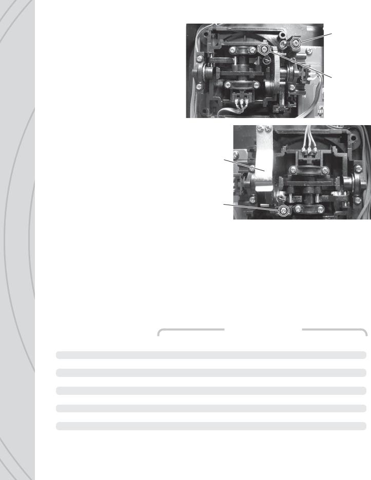
STICK TENSION: Silver screws on the back of each gimbal are used to adjust the stick tension. Turn the screw clockwise to make stick tension more fi rm. Turn the screw counter-clockwise to make stick tension more light.
THROTTLE RATCHET: A silver ratchet bar is mounted across the throttle gimbal. For smooth throttle feel for helicopter use, you may wish to remove this bar. Remove both screws which hold the ratchet bar then remove the bar.
DIGITAL STICK TRIMS
The trim controls for the four main channels are digital. Holding the trim lever will cause the servo output to move repeatedly. Trim positions are visible on the LCD’s home screen, and stored into that respective memory. Changing the model memory will also cause trim settings to change accordingly.
Left stick, up/down tension ratchet
Left stick, sideways tension adjustment
Right stick, up/down tension adjustment
Right stick, sideways tension adjustment
For aircraft with glow engines, the precise
position of the trim lever is helpful when determining the engine’s preferred idle point. When the throttle stick is above 50% full throttle it will not be possible to trim the throttle servo – even though the indicator on the LCD will move.
The amount of servo movement for each increment of a digital trim can be adjusted as desired, as explained in the TRIM STEP SETTING section on page 12.
TOGGLE SWITCHES
Each switch can be assigned to control one of a variety of functions as desired and described throughout this manual. The identifi cation of each switch by letter is marked on the Tx. The factory default switch assignments are as follows:
|
|
|
Default Functions |
|
Switch |
Type |
Airplane |
Helicopter |
Multi-Rotor |
|
|
|
|
|
A |
3-position |
Elevator D/R |
Timer Control |
Timer Control |
B |
3-position |
Flaps |
Gyro Gain |
Gyro Gain |
C |
3-position |
(no setting) |
(no setting) |
(no setting) |
D |
3-position |
Aileron D/R |
Ail/Ele/Rud D/R |
Ail/Ele/Rud D/R |
E |
3-position |
Rudder D/R |
Normal/Idle-up |
(no setting) |
F |
2-position mom. |
Trainer |
Throttle Cut |
(no setting) |
G |
3-position |
(no setting) |
(no setting) |
(no setting) |
H |
2-position |
(no setting) |
Throttle Hold |
Throttle Hold |
I |
Sweep Lever |
(no setting) |
(no setting) |
(no setting) |
J |
Sweep Lever |
(no setting) |
(no setting) |
(no setting) |
6

LCD,HOMEPROGRAMMINGSCREEN CONTROLS, MENU NAVIGATION
LCD contrast and backlight intensity are adjustable for optimum viewing. Six pushbuttons navigate the menus and settings. Single button pushes will result in a single incremental adjustment on-screen. Holding a button for a short time will result in slow scrolling of adjustments; continued holding will result in fast adjustments.
LEFT SIDE BUTTONS


 Press any time to see the servo position screen. Indicators for certain channels will change depending on model type, wing type, etc. Moving any Tx control will graphically be shown on this screen. When setting / adjusting mixes to determine if the mix is as desired, set the mix and then
view this screen. Move all controls to determine if the mix moves each respective channel as needed.
Quickly resets certain values and settings back to factory defaults. Press to backspace in the model and user name screens.
Jumps back to the previous screen, and removes certain pop-up messages from the screen.
RIGHT SIDE BUTTONS
Adjustment of values on-screen.
Moves the cursor up, and increases highlighted values/settings.
Moves the cursor down, and decreases highlighted values/settings.
To select or de-select a setting, or enter a screen. Press briefl y to access the SETTINGS menu. Press and hold to access the MODEL SETUP menu.
MENUS
The TTX850 has three types of menus.
The SYSTEM SETUP menu allows for setting basic operational functions for the radio itself.
Selecting and managing the model memories, configuring the radio for the structure of the airplane, helicopter, or multi-rotor is done in the MODEL SETUP menu. Most functions apply for all model types. Select functions are available for certain model types only.
Setting various radio functions to control the model is done in the SETTINGS menu. Some settings apply for all model types, while certain functions are available for certain model types only.
SYSTEM SETUP
Fundamental settings for the transmitter itself are located in this menu. With the power switch in the OFF position, press and hold ENTER, turn the power switch ON and wait for the SYSTEM SETUP screen to show. Move the cursor and press ENTER to select any setting. Press
 and
and
 to change settings. Press ENTER to confirm the setting.
7

USER NAME
Enter your name to identify the radio. The cursor will be under the first character. Press ENTER to highlight this character. Press 
 and
and 
 to fi nd the desired character, then ENTER to confirm. The cursor will automatically move to the next cursor. Repeat as necessary for up to 11 characters. Pressing CLEAR will move the cursor back one space and erase the character in that space. Press ESC when fi nished.
STICK MODE
The TTX850 is factory set to Mode 2 confi guration, but can be changed to Mode 1, 3, or 4 as explained below. To change modes in the programming, move the cursor to the STICK MODE line, highlight and press ENTER, then press 
 or
or 
 to fi nd the desired mode. Press ENTER to confi rm.
Mode |
Left Stick |
Right Stick |
1 |
elevator/rudder |
throttle/aileron |
2 |
throttle/rudder |
aileron/elevator |
3 |
aileron/elevator |
throttle/rudder |
4 |
throttle/aileron |
elevator/rudder |
In addition to programming changes, stick mode changes require relocation of gimbal stick parts to achieve the proper control. Go to www.tacticrc.com and click on the TTX850 link to fi nd directions for how to change gimbal settings.
CONTRAST
Adjust the LCD’s contrast level for optimum viewing.
SPEAKER VOLUME
Adjust the loudness of the radio’s beeper as desired. This volume setting affects all tones that are emitted from the radio including trim adjustments, alarms, programming changes, etc. Speaker volume for all alarms is not adjustable.
BATTERY ALARM
An alarm will sound and the display will show a warning when the Tx battery’s voltage drops to the level shown in this setting. Do NOT set this value too low, as the radio could lose power very rapidly as the battery nears full discharge and cause a loss of control of the model. Land the model immediately once this alarm has sounded!
VIBRATION POWER
Turn the vibration feedback ON or OFF.
BACK LIGHT
Adjust the intensity of the LCD’s red backlight.
Once all functions in this menu are set, press ESC to return to the home screen.
MODEL SETUP MENU – AIRPLANES
|
From the home screen, press and hold ENTER for 2 seconds to fi nd the MODEL SETUP menu for setting |
||
|
of fundamental operating parameters as explained here. |
||
|
MODEL SELECT |
||
|
Memories are available to store parameters for up to 30 different models. With this selection highlighted |
||
|
press ENTER. Press or |
|
to move the cursor up/down the screen to fi nd the desired memory to make |
|
|
||
8 |
active, and press ENTER twice to confi rm the selection and automatically return to the home screen. Or |
||
press ESC to return to the home screen. |
|||
Changing the model memory is not possible if the Tx battery voltage is too low. See the INPUT POWER section on page 4. It’s a good idea to keep a record of all settings in each memory as a backup in case parameters in a particular memory are accidentally changed, etc.
MODEL MANAGEMENT |
Model |
Management |
||
Shows basic information regarding the model setup |
Model :OO |
Name : |
|
|
Sensei SS1 |
||||
in the “Model” memory number at top-left. Move the |
Model Type : Airplane |
|||
cursor up or down to select / change the function to |
||||
Model Copy |
|
|
||
adjust, and press ENTER to adjust the function. |
|
|
||
Model Reset
Name: With the cursor on this line press ENTER. The method for setting the model name is the same as for entering the USER NAME as described on
page 7. The maximum number of characters is eleven. Press ESC when fi nished.
Model Type: Press 
 to place the cursor on this line, and ENTER to highlight the selection. Press
 or
or 
 to select the model type as airplane, helicopter, or quadcopter. Press ENTER to confirm.
Model Copy: To copy all parameters from one model memory to another, place the cursor at this line and press ENTER. The “COPY FROM” page will show. Highlight the memory to copy FROM and press ENTER. Now the “COPY TO” page will show.
Place the cursor over the memory number to copy TO, and press ENTER. The “COPY CONFIRM” screen will show. To abandon the copy function as shown on-screen, highlight “NO” and press ENTER to return to the “COPY TO” screen. Press ESC to return to the “MODEL MANAGEMENT” screen.
Otherwise, press 
 to highlight “YES” and press ENTER. All settings that previously existed in the receiving memory will be permanently erased. The display will return to the COPY TO screen. Return to the “MODEL SELECT” screen to confirm the copy function was successful by looking at the memory that was copied “to”.
Model Reset: Use this function to clear all parameters of any single memory except model type back to factory defaults. Enter this screen, move the cursor over the memory to reset and press ENTER. Select “NO” to cancel or “YES” to proceed with the reset, and press ENTER. The display will then return to the “MODEL RESET” screen.
Wireless Transfer: To transfer all parameters of one memory in this transmitter to another Tactic TTX850 transmitter, move the cursor to this line and press ENTER. Press 
 or
or 
 to select “Send” or “Receive”. Press ENTER, then
 or
or 
 to select the model number to send or receive data. Press ENTER to perform the function, or ESC to cancel.
|
Wireless |
Transfer |
|
|
OO |
Sensei |
SS1 |
Send |
|||
Receive OO |
Sensei |
SS1 |
|
Transferring . |
|
|
|
WING TYPE
This is for setting the type of tail and wing confi guration for the model. Depending on the mixes used and setup of the aircraft, it might be necessary to change the aileron, elevator, or rudder reversing settings to achieve the proper throw directions for the model.
For best results, selecting certain tail or wing types might require some servos to be connected to different outputs on the receiver (not the normal channel slots). The TTX850 will automatically map all controls accordingly. See the servo connection charts in this section for details.
TAIL SETTINGS |
|
|||
“Normal” is the factory default setting for the “TAIL” type. Move the cursor over “Normal”, press ENTER |
|
|||
then |
or |
|
to select from V-Tail, Delta (elevon), and 2 Elevator options. Press ENTER to confi rm the |
9 |
|
||||
selection. The charts below can aid in determining the preferred tail and fl ap setting for the model. |
||||

Normal: One servo each is used for aileron(s), elevator(s), and rudder.
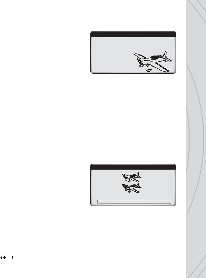
V-tail: Elevator and rudder channels are mixed. Two servos are used in the tail – one for each control surface, with connections as shown in the graphic below. V-tail mixing controls the airplane’s “pitch” and “yaw” axis at the same time. If the elevator and rudder functions appear reversed at the control surfaces, it may be necessary to swap the channel 2 and channel 4 servo plug positions in the Rx. The travel limits for each servo can be adjusted independently.
Delta wing (elevon): Elevator and aileron channels are mixed, useful for aircraft such as fl ying wings and other models not having a tail. Elevon mixing controls the airplane’s “pitch” and “roll” axis at the same time. One servo is used for each control surface. Travel limits for each servo can be adjusted separately. If the elevator and aileron functions appear reversed at the control surfaces, it may be necessary to swap the channel 1 and channel 2 servo plug positions at the Rx for the delta wing mix. If the delta wing option is selected, and the “FLAP” option below is set to 2AI1FL, the elevator channel will mix 100% to the aileron channel.
2-Elevators: Elevator channel 2 and another channel are mixed for aircraft which have two separate servos moving separate elevator surfaces. Both elevators move independently, and are independently adjustable for travel limits, etc. See the charts below for details.
FLAP SETTINGS
The “FLAP” setting allows for confi guration of the ailerons and/or fl aps of the airplane. Move the cursor over “1AI” to select from the following options:
1AI: Use this “1 aileron” setting for normal wing types having one aileron on each wing connected with a Y-harness or where one servo controls the movements of both ailerons simultaneously.
1AI & V-tail
1AI1FL: This “1 aileron |
1AI1FL & Normal |
|
1AI1FL & V-tail |
|
1AI1FL & 2 Elev |
||||
+ 1 fl ap” setting is for |
|
|
|
|
|
|
|
|
|
CH 1 |
Aileron |
|
CH 1 |
Aileron |
|
CH 1 |
Aileron |
||
wings |
having one |
|
|
||||||
servo |
(or 2 servos |
CH 2 |
Elevator |
|
CH 2 |
V- tail 1 |
|
CH 2 |
Elevator 1 |
on a Y-harness) that |
|
|
|||||||
CH 3 |
Throttle |
|
CH 3 |
Throttle |
|
CH 3 |
Throttle |
||
controls the ailerons on |
|
|
|||||||
both wings, and another |
CH 4 |
Rudder |
|
CH 4 |
V- tail 2 |
|
CH 4 |
Elevator 2 |
|
servo that controls the |
CH 5 |
Flap |
|
CH 5 |
Flap |
|
CH 5 |
Flap |
|
flaps on both wings |
|
|
|||||||
|
|
|
|
|
|
|
|
||
(both servos moving |
CH 6 |
Aux 1 |
|
CH 6 |
Aux 1 |
|
CH 6 |
Rudder |
|
in the same direction). |
CH 7 |
Aux 2 |
|
CH 7 |
Aux 2 |
|
CH 7 |
Aux 1 |
|
Connect the aileron |
|
|
|||||||
|
|
|
|
|
|
|
|
||
servo to Rx channel 1, |
CH 8 |
Aux 3 |
|
CH 8 |
Aux 3 |
|
CH 8 |
Aux 2 |
|
and the fl ap servo to |
|
|
|
|
|
|
|
|
|
10 |
channel 5 (not available for delta). See the CH5-CH8 Set section for switch assignments for fl aps. |
|
 Loading...