


TM
2.4GHZ RADIO CONTROL SYSTEM
INSTRUCTION MANUAL
™
Thank you for making the Tactic
TTX300 2.4GHz SLT system
your choice for radio control!
This system uses modern 2.4GHz Spread
Spectrum technology – an innovation that
allows for automatic channel selection and
interference-free control of R/C models.
TTX300
For safe operation and best results, it’s strongly
recommended to read this manual in its entirety
before use! Also read and understand the instructions
included with the model. Damage resulting from
misuse or modifi cation will void your warranty.
FEATURES
● 2.4GHz Spread Spectrum Technology
● Ergonomic and stylish case design
● Transmitter can bind to multiple receivers
● Tiny, lightweight receiver with internal antenna
● Built-in fail-safe
● Steering and Throttle trim dials
● Steering rate adjustment
● Power LED with low battery warning indication
● Multi-function programmable 3rd channel
● Steering and throttle end point adjustments
TRANSMITTER
IMPORTANT: Do not operate an R/C model with weak batteries as
it could result in reduced range and/or possible loss of control!
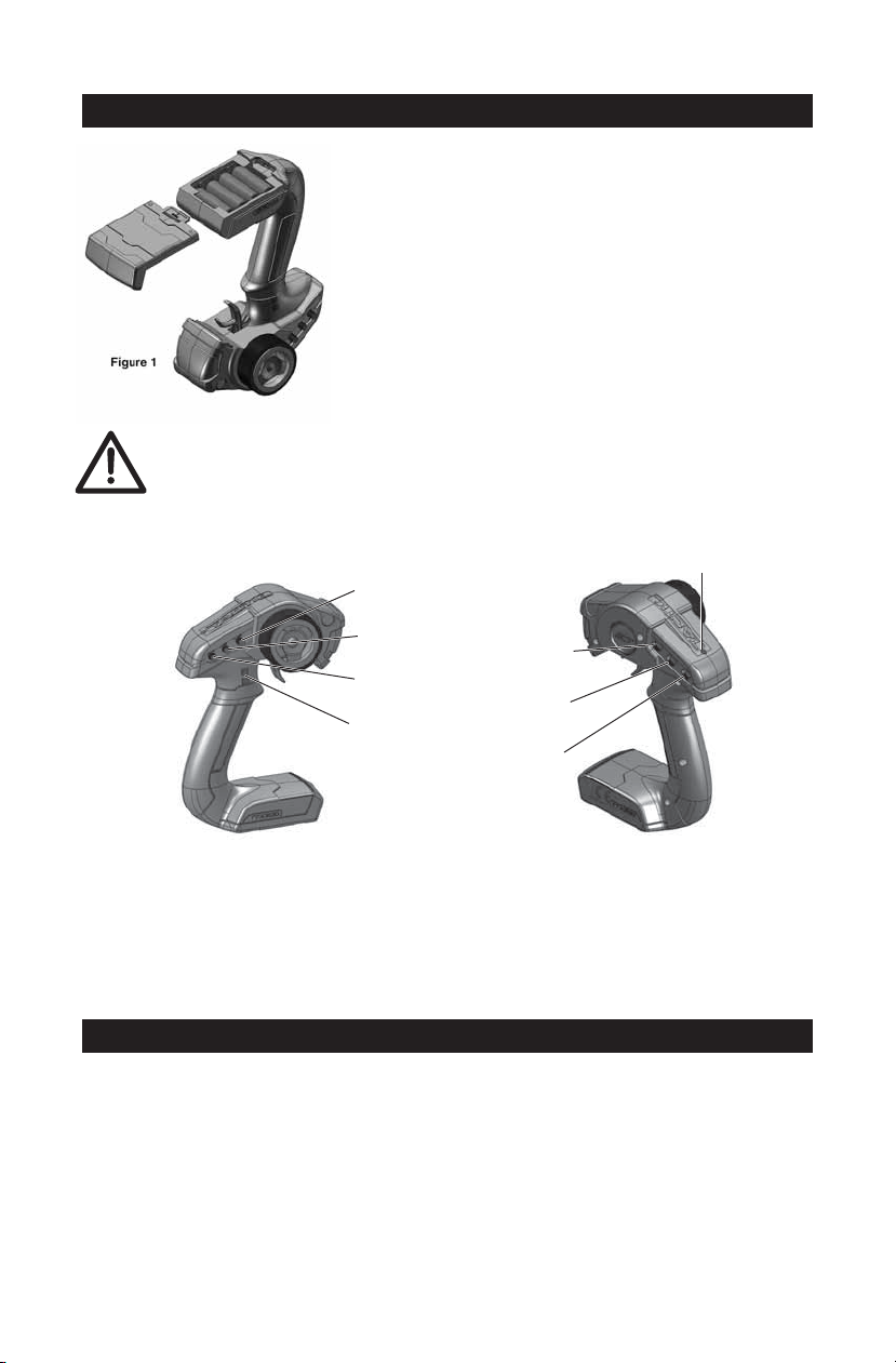
The transmitter (Tx) requires 4 “AA” batteries.
Non-rechargeable alkaline or rechargeable nickelcadmium (NiCd) or nickel-metal hydride (NiMH) cells
can be used. Do not mix old and new cells, or mix
non-rechargeable alkaline cells with rechargeable
NiCd or NiMH cells, etc. See the SERVOS AND
ACCESSORIES section at the end of this manual
for optional rechargeable NiCd and NiMH batteries
and chargers. Note the TTX300 transmitter does
not include a charge jack for rechargeable cells. A
separate “AA” cell charger will be necessary.
Figure 2
Steering
Trim
Throttle
Trim
Steering
Rate
Channel 3
Buttons
Steering
Reversing
Throttle
Reversing
On/Off
Power
Switch
Power
LED
Press the power switch to turn the Tx on (see fi gure 2). The “POWER” LED
should illuminate. If not, turn off the Tx and check the batteries to make sure
each cell is fi rmly in place and in the proper direction. If the Tx LED blinks, the
batteries are low on power and should be replaced.
BIND THE RECEIVER TO THE TRANSMITTER
For proper installation and operation of the 2.4GHz transmitter and receiver
system, it is necessary to “bind” them together electronically. This ensures
sole communication between the two and prevents other transmitters from
being able to control the receiver. To bind the Tx and Rx:
1. Turn on the transmitter.
2. Apply power to the receiver (see the INSTALLATION section that follows
for how to do this).
2
3. If the receiver’s LED fl ashes once and then stays on, the Rx is already
bound to the Tx and you can skip to the next section. Otherwise, push
and hold the receiver’s “BIND” button until its LED glows red and then
turns off after about one second.
4. Release the bind button.
5. If the binding is successful, the LED will fl ash once and then remain ON.
6. Test for proper Tx / Rx functionality by completing the next section. If it
doesn’t seem the radio has bound properly, repeat steps 1-6 above.
INSTALLATION
Receiver: Mount the receiver as specifi ed in your model’s instructions. As a
guideline, mount in a secure location using double-sided tape. Route the servo
wires so they do not interfere with any moving parts. For boat applications,
it’s highly recommended to wrap the receiver in a balloon or enclose it in a
water-tight box.
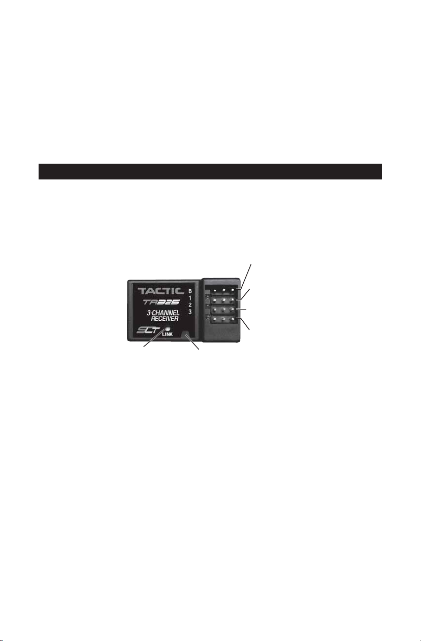
Figure 3
Link
Button
Link LED
(B) Battery/
Switch
(1) Steering
Servo
(2) Throttle
Servo
Channel 3
Servos: See the SERVOS AND ACCESSORIES section at the end of this
manual for a full list of optional servos. CENTER THE TRIM DIALS on the Tx.
Mount the servos inside the model and connect the linkages to the servo using
an appropriate length servo arm. Make sure all mechanical linkages are free
of obstructions and can move smoothly. Connect the servos to the receiver as
shown in Figure 3. Turn the transmitter’s trim dials to fi nely adjust the servo’s
center point as needed to match the installation.
Electronic Speed Control (ESC): If using an electronic speed control,
connect it to channel 2 of the receiver (throttle). Center the transmitter’s
throttle trim and follow the ESC instructions for programming.
3

PROGRAMMING
Several of the TTX300 features are adjusted electronically by entering the
programming mode. To enter the programming mode, follow these steps:
1. With the transmitter turned off, turn steering wheel full right, pull the trigger
to the full throttle position and turn the transmitter’s power switch to ON. The
LED will fl ash to confi rm when performed correctly.
2. Release the wheel and trigger at this time.
End Point Adjustments
Steering:
1. Enter programming mode.
2. LEFT EPA: Turn wheel FULL
COUNTERCLOCKWISE, use 3rd
channel push buttons to adjust.
3. RIGHT EPA: Turn wheel FULL
CLOCKWISE, use 3rd channel
push buttons to adjust.
Channel 3:
The TTX300 3rd channel is programmable and offers a wide variety of options
to suit many applications. Selecting the number of positions and end point
adjustments are performed at the same time. To change the function and set
end point adjustments for CH3, follow these steps:
REVERSE: Press and hold the bottom push button and power ON
transmitter. The LED will fl ash one time. After 3 seconds, the LED will fl ash
two times when performed correctly. Release the bottom push button.
MULTI-POSITION: The TTX300 3rd channel can be programmed to
function as 2 position, 3 position, 4 position or proportional control switch.
Selecting each position and end points for each position are performed
simultaneously. The default position of CH3 is 2 position. To change the
function of CH3, follow these steps:
1. Enter programming mode: Press and hold the top push button, power
ON transmitter. Continue to hold until the LED fl ashes fi ve times.
Release the top push button.
2.
Use CH3 push buttons to adjust CH3
accessory/servo to desired 1st position.
Turn steering wheel clockwise (right) to
confi rm position 1. The LED will fl ash
one time to confi rm position 1 has been
saved. Note: Press and holding CH3
push buttons will adjust rapidly. Press
and release will fi nely adjust positions.
Throttle:
1. Enter programming mode.
2. THROTTLE EPA: Pull trigger to the
FULL THROTTLE position, use 3rd
channel push buttons to adjust.
3. BRAKE EPA: Push trigger to the
FULL BRAKE position, use 3rd
channel push buttons to adjust.
First use
CH3 buttons
to set.
4
Then turn wheel
clockwise
to confirm.

Moving the steering wheel during adjustment of CH3 will save the position.
Do not move steering wheel unless position is ready to be saved.
3.
Use CH3 push buttons to adjust CH3 accessory/servo to desired 2nd
position. Turn steering wheel clockwise (right) to confi rm position 2.
The LED will fl ash two times to confi rm position 2 has been saved. If
programming for two position switch, skip to step 6. Otherwise, proceed
to step 5 to program 3rd or 4th position.
4. If programming as 3 or 4 position switch, follow the procedures in
steps 2 and 3 and select additional positions (3 and/or 4). Turn steering
wheel clockwise (right) to confi rm each individual position. The LED will
fl ash in relation to the position that is being saved. Three fl ashes is 3rd
position, 4 fl ashes is 4th position. Proceed to step 6 when programming
as 3 or 4 position switch has been completed.
5.
To program CH3 as proportional, enter programming mode and select
desired position 1 as listed in Step 1 above. Use CH3 push buttons to
adjust to desired end point and turn steering wheel clockwise four times.
The LED will fl ash fi ve times to confi rm the position has been saved.
6. After programming of CH3 is completed, turn off transmitter to save
settings.
SYSTEM CHECK
Turn on the Tx, then the Rx. Make sure all servos operate according to the
movement of the Tx controls (refer to fi gure 4).
Steering: Turn the steering wheel
left and right. Make sure there are
Reversing
Switches
Steering
(L & R)
no obstructions with the steering
servo’s movements, and the servo
moves in the proper direction.
If the steering wheel is turned
to the right but the model turns
left, reverse the position of the
Steering Reversing switch.
Steering
Rate
Forward Throttle
Reverse
or Brake
Figure 4
Steering Rate: This dial adjusts the limits that the steering servo can travel
on each side. Turning the dial will widen or narrow the steering end points.
Adjusting this dial to your preference can help to customize control of steering
in different applications.
Throttle: Squeeze the throttle trigger to make the car move forward. If the
car moves backwards, reverse the position of the Throttle Reversing switch.
(See the model’s instruction manual for specifi c set-up instructions.) Push the
trigger forward for reverse or brake function.
Failsafe: This radio system includes a “fail-safe” function, which will
5

automatically center (bring to neutral) all servos if the receiver loses signal
communications from the transmitter. When the receiver regains signal it will
automatically resume normal function.
Range Check: The “range” or safe operating distance from the Tx to the Rx is
typically as far as you can clearly see the model. Before operating the model,
perform a simple range check to make sure the transmitter maintains good
radio contact with the receiver within your operating area.
SYSTEM CHECK
● NEVER allow water or moisture to make contact with the
electronic components inside the transmitter, receiver,
servos, switch harness, etc.! This could lead to failure or
improper functionality of components and poor control of
vehicle which could pose a safety hazard.
● NEVER operate R/C equipment if you are physically impaired as it could
pose a safety hazard to yourself or others in the area.
● NEVER allow small children to operate/control model R/C equipment
without the supervision of an adult.
● NEVER allow the transmitter’s throttle trigger to accidentally be moved
away from the neutral position while the vehicle is powered up.
● ALWAYS range check the radio system before use.
● ALWAYS make sure that all transmitter movements operate all servos
properly in the model.
● Do not store your radio equipment in extremely hot or cold locations, in
direct sunlight, or in locations with high humidity. Store R/C equipment in
a cool and dry location.
● Do not allow chemicals to come in contact with any parts of the radio
system. Substances such as glow fuel, gasoline, CA glue, etc. could
permanently damage plastic parts of the radio system.
● If rechargeable batteries were installed in the transmitter, remove the
batteries before placing the radio in long-term storage.
TROUBLESHOOTING
RANGE IS SHORT: Interference – check Rx installation and servo connections.
Low Tx or Rx battery – replace the batteries or recharge if applicable. Crash
damage – send the radio to Hobby Services for repair.
RUN TIME IS SHORT:
servo linkages causing excess battery drain – free the linkages/pushrods.
Low Tx or Rx batteries – replace the batteries. Obstructed
6

Tx POWER SWITCH ON BUT SERVOS DO NOT FUNCTION: Tx or Rx
batteries are low or – replace the batteries or check Tx or Rx battery polarity.
Switch harness or ESC is connected incorrectly – check all connections and
the ESC instruction manual. Rx is not binded to the Tx properly – perform
binding process again. Rx antenna located too closely to engine, motor,
servos or other moving mechanical parts which might be creating unwanted
electrical noise – relocate the Rx inside the model or relocate the ESC.
INTERFERENCE OR SERVOS GLITCHING:
model more closely to the transmitter. Outside radio interference (pagers,
strong industrial or other commercial transmitters in the area) – check your local
R/C club for confi rmation of dangerous/interfering frequencies in your area.
CONTROL SURFACE MOVES IN THE WRONG DIRECTION: Change the
position of that channel’s reversing switch.
ONLY ONE SERVO GLITCHES: Servo is bad – replace the servo or send to
Hobby Services for repair.
Contact Hobby Services for other problems.
Out of range – operate the
TTX300 SPECIFICATIONS
TRANSMITTER
Channels: 3
Frequencies: 2.403-2.480GHz
Protocol: Tactic SLT
Modulation: FHSS spread spectrum
Input Power: 3.40-7.00V DC, four 1.5V
alkaline or 1.2V NiCd/NiMH
“AA” single cells.
Output Power: <0.1W
Power On Indicator: red LED
RECEIVER
Channels: 3
Receiving Frequencies: 2.403-2.480GHz
Modulation: FHSS spread spectrum
Input Power: 3.40 - 7.00V DC, four “AA”
alkaline, NiCd or NiMH cells
Dimensions: .75 x .55 x 1.4"
(19 x 14 x 35 mm)
Weight: 18 oz (5.2 g)
FCC STATEMENT
This device complies with part 15 of the FCC rules. Operation is subject to the
following two conditions.
(1) This device may not cause harmful interference.
(2) This device must accept any interference received, including
interference that may cause undesired operation.
FCC Rf Radiated Exposure Statement: The equipment complies with FCC
Rf radiation exposure limits set forth for an uncontrolled environment. This
equipment should be installed and operated with a minimum distance of 20
centimeters between the radiator and your body.
NOTE: THE MANUFACTURER IS NOT RESPONSIBLE FOR ANY RADIO
OR TV INTERFERENCE CAUSED BY UNUAUTHORIZED MODIFICATIONS
TO THIS EQUIPMENT. SUCH MODIFICATIONS COULD VOID THE USER’S
AUTHORITY TO OPERATE THE EQUIPMENT.
7

SERVOS AND ACCESSORIES
Stock #
TACM0235
TACM0240
TACM0245
TACM0247
TACM0255
TACM0257
TACM0265
TACM2000
TACM2001
TACM2002
TACM2020
TACM2090
TACM2091
TACM2092
TACM2093
DTXP4704
DTXP4191
DTXP4225
DTXP4235
DTXP4245
DTXP4615
DTXC3164
DTXC3165
DTXC3166
DTXC3172
DTXC3174
Description
TSX35 Standard Servo Sport
TSX40 Standard Servo High Speed MG 2BB
TSX45 Standard Servo High Torque MG 2BB
TSX47 Standard Servo Digital High Torq MG 2BB
TSX55 Standard Servo Ultra Torque MG 2BB
TSX57 Standard Servo Digital Ultra Torq MG 2BB
TSX65 Std Servo Digital Ultra Torq High Volt MG 2BB
Switch Harness FUT J Conn No Charge Lead
Switch Harness w/Charge Lead Futaba J
Switch Harness w/Charge Plug Universal
4 Cell AA Battery Holder w/Fut J Connector
Servo Extension 6” (150mm) Futaba J
Servo Extension 6” (150mm) Futaba J (10)
Servo Extension 6” (150mm) Universal
Servo Extension 12” (300mm) Futaba J
Onyx AA Alkaline Battery (4)
Onyx 110 AC/DC Peak Charger
Onyx 225 AC/DC Advanced Charger
Onyx 235 AC/DC Advanced Charger with Balancing
Onyx 245 AC/DC Dual Charger with Balancing
Power Kit w/ 1500mAh NiMH, AC Wall Charger, 8 “AA” Alkalines
Onyx 1/10th 3930kV Brushless System
Onyx 1/10th 4420kV Brushless System
Onyx 1/10th 5900kV Brushless System
Onyx 1/10th 3650kV Short Course Brushless System
Onyx 1/10th 4550kV Short Course Brushless System
CE COMPLIANCE INFORMATION FOR THE EUROPEAN UNION
INSTRUCTIONS FOR DISPOSAL OF WASTE EQUIPMENT BY
PRIVATE USERS IN THE EUROPEAN UNION:
This symbol on the product or its packaging indicates this product
must not be disposed of with other household waste. Instead, it
is the user’s responsibility to dispose of their waste equipment by
handing it over to a designated collection point for the recycling of
waste electrical and electronic equipment. The separate collection
and recycling of your waste equipment at the time of disposal will help to
conserve natural resources and ensure that it is recycled in a manner that
protects human health and the environment. For more information about
where you can drop off your waste equipment for recycling, please contact
your local city offi ce, your household waste disposal service or location where
you purchased the product.
8

DECLARATION OF CONFORMITY:
Product: Tactic TTX300 2.4GHz 3-Channel Pistol Tx Rx
Item number: TACJ0300
Equipment class: 1
TACTIC TTX300 TRANSMITTER AND TACTIC TR325 RECEIVER:
The objects of the declaration described here are in conformity with article
3.1(a) the requirements of safety contained in the European 2006/95/EC
Directive and article 3.1(b) the requirements of EMC contained in Directive
2004/108/EC and article 3.2 requirements of radio equipment in Directive
1999/5/EC.
EN 60950-1:2006 + A11:2009 + A1:2010 + A12:2011
ETSI EN 300 328 V1.8.1
ETSI EN 301 489-1 V1.9.2 (2011-09)
ETSI EN 301 489-17 V2.2.1 (2012-09)
ETSI EN 62311:2008
US standard: FCC 15.247
Japan standard: ARIB STD-T66
Canada standard: RSS210&RSS GEN
Product name: TTX300
Product type: TACJ0300
Brand: Tactic
Tactic
c/o Hobbico, Inc.
2904 Research Road
Champaign, IL USA 61826
INDUSTRY CANADA NOTICE
This device complies with Industry Canada license-exempt RSS standard(s).
1. Operation is subject to the following two conditions: (1) this device may not
cause interference, and (2) this device must accept any interference, including
interference that may cause undesired operation of the device. 2. Changes or
modifi cations not expressly approved by the party responsible for compliance
could void the user’s authority to operate the equipment.
This equipment complies with IC radiation exposure limits set forth for an
uncontrolled environment. In order to avoid the possibility of exceeding the IC
radio frequency exposure limits, Human proximity to the antenna shall not be
less than 20cm (8 inches) during normal operation.
Avis d’Industrie Canada
Le présent appareil est conforme aux CNR d’Industrie Canada applicables
aux appareils radio exempts de licence. L’exploitation est autorisée aux deux
conditions suivantes : (1) l’appareil ne doit pas produire de brouillage, et (2)
l’utilisateur de l’appareil doit accepter tout brouillage radioélectrique subi,
même si le brouillage est susceptible d’en compromettre le fonctionnement.
Cet appareil numérique ne dépasse pas les Rèlements sur l’interférence
radio par un appareil numérique de classe B stipulées dans les Règlement
sur l’interférence redio d’industrie Canada.
9

2.Les changements ou modifi cations de cette unité non expressément
approuvés par la partie responsable de la conformité pourraient annuler
l’autorité de l’utilisateur à utiliser l’équipement.
IC RF Déclaration sur la radioexposition:
Cet appareil est conforme avec I’exposition aux radiations IC Défi nies pour
un environnement non contrôlé. Les utilisateurs fi naux dovivent suivre les
instructions de fonctionnement spécifi ques pour satisfaire la conformité aux
expositions RF.
WARRANTY AND REPAIR
1-YEAR LIMITED WARRANTY
Tactic warrants this product to be free from defects in materials and workmanship
for a period of one (1) year from the date of purchase. During that period, Tactic
will, at its option, repair or replace without service charge any product deemed
defective due to those causes. You will be required to provide proof of purchase
(invoice or receipt). This warranty does not cover damage caused by abuse,
misuse, alteration or accident. If there is damage stemming from these causes
within the stated warranty period, Tactic will, at its option, repair or replace it
for a service charge not greater than 50% of its then current retail list price. Be
sure to include your daytime telephone number or e-mail address in case we
need to contact you about your repair. This warranty gives you specifi c rights.
You may have other rights, which vary from state to state.
For service on your Tactic product, send it post paid and insured to:
HOBBY SERVICES Tel: (217) 398-0007
3002 N. Apollo Dr., Suite 1 (9:00am - 5:00pm CST, M-F)
Champaign, IL 61822 E-mail: hobbyservices@hobbico.com
*For warranty and service information if purchased outside the U.S.A. or Canada, ask
your retailer for more information.
In the European Union, send it postpaid and insured to:
Service Abteilung Revell GmbH Tel: 01805-110111 (nur für Deutschland)
Henschelstrasse 20-30 E-mail: Hobbico-Service@Revell.de
32257 Bünde Germany
Distributed in the EU by Revell GmbH, Bünde Germany
● This product is suitable only for people of 14 years and older. This is not a toy!
● WARNING: CHOKING HAZARD - May contain small parts. Keep away from
children under 3 years. Please retain packaging for future reference.
● No part of this manual may be reproduced in any form without prior permission.
● The contents of this manual are subject to change without prior notice.
● Tactic is not responsible for the use of this product.
10

QUICK REFERENCE CHART
REVERSING
FUNCTION
Steering
Wheel
Steering
Trim
CHANNEL 1
Steering
Dual Rates
SWITCH DIRECTION
Normal
Normal
n/a
Clockwise (right)
Anti-Clockwise (left)
Clockwise (right)
Anti-Clockwise (left)
Clockwise (right)
Anti-Clockwise (left)
REVERSING
FUNCTION
Throttle
Trigger
Throttle
Trim
CHANNEL 2
FUNCTION
Reverse Normal
2, 3, or 4
Position
Switch
CHANNEL 3
Proportional
FUNCTION
CH1 EPA
CH2 EPA
END POINT ADJUSTMENTS
CH3 EPA
SWITCH DIRECTION
Normal
Normal
Throttle (pull)
Brake (push)
Clockwise
Anti-Clockwise
ACTION
Press and hold CH3 bottom push button. Power on transmitter.
Continue to hold until LED flashes. Release bottom push button.
Refer to CHANNEL 3 PROGRAMMING section (page 4).
Refer to CHANNEL 3 PROGRAMMING section (page 4).
ACTION
Enter Programming Mode: Wheel full clockwise (right),
trigger full throttle (pull), power on Tx
Left EPA
Right EPA
Enter Programming Mode: Wheel full clockwise (right),
trigger full throttle (pull), power on Tx
Throttle EPA
Brake EPA
Enter Programming Mode: Wheel full clockwise (right),
trigger full throttle (pull), power on Tx
Refer to CHANNEL 3 PROGRAMMING section (page 4).
Turn wheel anti-clockwise.
Use CH3 buttons to adjust.
Turn wheel clockwise.
Use CH3 buttons to adjust.
Pull trigger to full throttle.
Use CH3 buttons to adjust.
Push trigger to full brake.
Use CH3 buttons to adjust.
SERVO
ACTION
Anti-Clockwise
Clockwise
Anti-Clockwise
Clockwise
Wide
Narrow
SERVO
ACTION
Clockwise
Anti-Clockwise
Anti-Clockwise
Clockwise
settings from
Factory Reset.
settings from
Factory Reset.
DEFAULT
SETTING
Mechanical.
No default
DEFAULT
SETTING
Mechanical.
No default
DEFAULT
SETTING
X
DEFAULT
SETTING
0
0
0
0
0
FUNCTION
Factory
Reset
DEFAULT
ACTION
Wheel full anti-clockwise (left), trigger full brake (push), power
on transmitter. LED will flash 5x and reset radio to default.
11
See Above
DEFAULT
SETTING

tacticrc.com
TM
FCC ID: IYFTTX300
© 2014 Tactic, a Hobbico® company Made in China
TACJ0300 v2.1
 Loading...