


TM
TTX650
2.4GHz 6-CHANNEL
C O M P U T E R R A D I O INSTRUCTION MANUAL
Tactic’s TTX650 computer transmitter uses the advanced 2.4GHz spread spectrum SLT “Secure Link Technology” protocol for solid, interference-free control of R/C models. Ballbearing gimbals, a wireless trainer system, 20 model memories, and advanced programming options are just a few of the benefits which can be used on models of all sizes. Tactic 2.4GHz transmitters are compatible only with Tactic brand receivers and those utilizing the SLT protocol.
™
For safe operation and best results, it’s strongly recommended to read this manual in its entirety before
use! Also read and understand the instructions included with the model. Damage resulting from misuse or modification will void your warranty.

TABLE OF CONTENTS
SLT TECHNOLOGY, Tx-R, AND COMPATIBLE RECEIVERS . . . . . . . . . . . . . . . . . . .5 RECEIVER INSTALLATION . . . . . . . . . . . . . . . . . . . . . . . . . . . . . . . . . . . . . . . . . . . . .5 TTX650 POWER SYSTEM. . . . . . . . . . . . . . . . . . . . . . . . . . . . . . . . . . . . . . . . . . . . . .5 Input Power . . . . . . . . . . . . . . . . . . . . . . . . . . . . . . . . . . . . . . . . . . . . . . . . . . . . . .5 Charge Jack and Rechargeable Batteries . . . . . . . . . . . . . . . . . . . . . . . . . . . . . . .6 Power LED . . . . . . . . . . . . . . . . . . . . . . . . . . . . . . . . . . . . . . . . . . . . . . . . . . . . . . .6 FLIGHT CONTROLS . . . . . . . . . . . . . . . . . . . . . . . . . . . . . . . . . . . . . . . . . . . . . . . . . .6 Gimbal Sticks . . . . . . . . . . . . . . . . . . . . . . . . . . . . . . . . . . . . . . . . . . . . . . . . . . . . . 7 Stick Tension and Throttle Ratchet. . . . . . . . . . . . . . . . . . . . . . . . . . . . . . . . . . . . . 7 Case Separation and Assembly. . . . . . . . . . . . . . . . . . . . . . . . . . . . . . . . . . . . . . . 7 Digital Stick Trims. . . . . . . . . . . . . . . . . . . . . . . . . . . . . . . . . . . . . . . . . . . . . . . . . .8 Toggle Switches . . . . . . . . . . . . . . . . . . . . . . . . . . . . . . . . . . . . . . . . . . . . . . . . . . .8 Antenna . . . . . . . . . . . . . . . . . . . . . . . . . . . . . . . . . . . . . . . . . . . . . . . . . . . . . . . . .8 HOME SCREEN. . . . . . . . . . . . . . . . . . . . . . . . . . . . . . . . . . . . . . . . . . . . . . . . . . . . . .9 MENUS . . . . . . . . . . . . . . . . . . . . . . . . . . . . . . . . . . . . . . . . . . . . . . . . . . . . . . . . . . . .9 LCD AND PROGRAMMING CONTROLS, MENU NAVIGATION. . . . . . . . . . . . . . . .10 SYSTEM SETUP . . . . . . . . . . . . . . . . . . . . . . . . . . . . . . . . . . . . . . . . . . . . . . . . . . . . 11 User Name. . . . . . . . . . . . . . . . . . . . . . . . . . . . . . . . . . . . . . . . . . . . . . . . . . . . . . 11 Stick Mode . . . . . . . . . . . . . . . . . . . . . . . . . . . . . . . . . . . . . . . . . . . . . . . . . . . . . . 11 Contrast . . . . . . . . . . . . . . . . . . . . . . . . . . . . . . . . . . . . . . . . . . . . . . . . . . . . . . . .12 Beep Volume . . . . . . . . . . . . . . . . . . . . . . . . . . . . . . . . . . . . . . . . . . . . . . . . . . . .12 Battery Alarm . . . . . . . . . . . . . . . . . . . . . . . . . . . . . . . . . . . . . . . . . . . . . . . . . . . .12 MODEL SETUP MENU – AIRPLANES . . . . . . . . . . . . . . . . . . . . . . . . . . . . . . . . . . .13 Model Select . . . . . . . . . . . . . . . . . . . . . . . . . . . . . . . . . . . . . . . . . . . . . . . . . . . .13 Model Management . . . . . . . . . . . . . . . . . . . . . . . . . . . . . . . . . . . . . . . . . . . . . . .13 Wing Type . . . . . . . . . . . . . . . . . . . . . . . . . . . . . . . . . . . . . . . . . . . . . . . . . . . . . .15 Flap Settings . . . . . . . . . . . . . . . . . . . . . . . . . . . . . . . . . . . . . . . . . . . . . . . . . . . .15 Tail Settings . . . . . . . . . . . . . . . . . . . . . . . . . . . . . . . . . . . . . . . . . . . . . . . . . . . . .15 Channel Assignments . . . . . . . . . . . . . . . . . . . . . . . . . . . . . . . . . . . . . . . . . . . . . 17 Warnings . . . . . . . . . . . . . . . . . . . . . . . . . . . . . . . . . . . . . . . . . . . . . . . . . . . . . . . 17 Trainer . . . . . . . . . . . . . . . . . . . . . . . . . . . . . . . . . . . . . . . . . . . . . . . . . . . . . . . . .18 Trim Setting . . . . . . . . . . . . . . . . . . . . . . . . . . . . . . . . . . . . . . . . . . . . . . . . . . . . .18 SETTINGS MENU – AIRPLANES . . . . . . . . . . . . . . . . . . . . . . . . . . . . . . . . . . . . . . .18 Servo Set (reverse, sub-trim, travel limits) . . . . . . . . . . . . . . . . . . . . . . . . . . . . . .18 Dual-Rates and Exponential . . . . . . . . . . . . . . . . . . . . . . . . . . . . . . . . . . . . . . . .19 CH5 and CH6 Set . . . . . . . . . . . . . . . . . . . . . . . . . . . . . . . . . . . . . . . . . . . . . . . .20 Throttle Curve . . . . . . . . . . . . . . . . . . . . . . . . . . . . . . . . . . . . . . . . . . . . . . . . . . . 21 Throttle Cut . . . . . . . . . . . . . . . . . . . . . . . . . . . . . . . . . . . . . . . . . . . . . . . . . . . . .22
2

Aileron Differential . . . . . . . . . . . . . . . . . . . . . . . . . . . . . . . . . . . . . . . . . . . . . . . .23
Aileron Mixer . . . . . . . . . . . . . . . . . . . . . . . . . . . . . . . . . . . . . . . . . . . . . . . . . . . .24
Rudder Mixer . . . . . . . . . . . . . . . . . . . . . . . . . . . . . . . . . . . . . . . . . . . . . . . . . . . .25
Flap Mixer . . . . . . . . . . . . . . . . . . . . . . . . . . . . . . . . . . . . . . . . . . . . . . . . . . . . . .25
Air Brake Set . . . . . . . . . . . . . . . . . . . . . . . . . . . . . . . . . . . . . . . . . . . . . . . . . . . .26
Programmable Mixer . . . . . . . . . . . . . . . . . . . . . . . . . . . . . . . . . . . . . . . . . . . . . . 27
Rf Output . . . . . . . . . . . . . . . . . . . . . . . . . . . . . . . . . . . . . . . . . . . . . . . . . . . . . . .28
Timer . . . . . . . . . . . . . . . . . . . . . . . . . . . . . . . . . . . . . . . . . . . . . . . . . . . . . . . . . .28
MODEL SETUP MENU – HELICOPTERS. . . . . . . . . . . . . . . . . . . . . . . . . . . . . . . . .29
Swash Type . . . . . . . . . . . . . . . . . . . . . . . . . . . . . . . . . . . . . . . . . . . . . . . . . . . . .29
SETTINGS MENU – HELICOPTERS. . . . . . . . . . . . . . . . . . . . . . . . . . . . . . . . . . . . .30
Servo Set, Dual-Rates, Exponential, RF Output, Timer. . . . . . . . . . . . . . . . . . . .30
Throttle Cut . . . . . . . . . . . . . . . . . . . . . . . . . . . . . . . . . . . . . . . . . . . . . . . . . . . . . 31
Throttle Hold . . . . . . . . . . . . . . . . . . . . . . . . . . . . . . . . . . . . . . . . . . . . . . . . . . . . 31
Throttle Curve . . . . . . . . . . . . . . . . . . . . . . . . . . . . . . . . . . . . . . . . . . . . . . . . . . .32
Pitch Curve . . . . . . . . . . . . . . . . . . . . . . . . . . . . . . . . . . . . . . . . . . . . . . . . . . . . .33
Gyro Mixing . . . . . . . . . . . . . . . . . . . . . . . . . . . . . . . . . . . . . . . . . . . . . . . . . . . . .34
Swash Mixing. . . . . . . . . . . . . . . . . . . . . . . . . . . . . . . . . . . . . . . . . . . . . . . . . . . .34
Throttle Mixing . . . . . . . . . . . . . . . . . . . . . . . . . . . . . . . . . . . . . . . . . . . . . . . . . . .35
Rudder Mixing . . . . . . . . . . . . . . . . . . . . . . . . . . . . . . . . . . . . . . . . . . . . . . . . . . .35
Swash Ring . . . . . . . . . . . . . . . . . . . . . . . . . . . . . . . . . . . . . . . . . . . . . . . . . . . . .35
Programmable Mixer . . . . . . . . . . . . . . . . . . . . . . . . . . . . . . . . . . . . . . . . . . . . . .36
LINK THE RX TO THE TX . . . . . . . . . . . . . . . . . . . . . . . . . . . . . . . . . . . . . . . . . . . . .36
FAILSAFE FUNCTION . . . . . . . . . . . . . . . . . . . . . . . . . . . . . . . . . . . . . . . . . . . . . . . . 37
WIRELESS TRAINER . . . . . . . . . . . . . . . . . . . . . . . . . . . . . . . . . . . . . . . . . . . . . . . . 37
RANGE TEST. . . . . . . . . . . . . . . . . . . . . . . . . . . . . . . . . . . . . . . . . . . . . . . . . . . . . . .39
FIRMWARE UPDATES. . . . . . . . . . . . . . . . . . . . . . . . . . . . . . . . . . . . . . . . . . . . . . . .40
WARNING INDICATIONS. . . . . . . . . . . . . . . . . . . . . . . . . . . . . . . . . . . . . . . . . . . . . .40
SYSTEM CHECK AND OPERATION. . . . . . . . . . . . . . . . . . . . . . . . . . . . . . . . . . . . .40
FLYING THE AIRCRAFT . . . . . . . . . . . . . . . . . . . . . . . . . . . . . . . . . . . . . . . . . . . . . . 41
IMPORTANT WARNINGS AND PRECAUTIONS. . . . . . . . . . . . . . . . . . . . . . . . . . . .42
TTX650 SPECIFICATIONS. . . . . . . . . . . . . . . . . . . . . . . . . . . . . . . . . . . . . . . . . . . . .43
TROUBLESHOOTING . . . . . . . . . . . . . . . . . . . . . . . . . . . . . . . . . . . . . . . . . . . . . . . .43
SAFETY GUIDE . . . . . . . . . . . . . . . . . . . . . . . . . . . . . . . . . . . . . . . . . . . . . . . . . . . . .44
ACCESSORIES . . . . . . . . . . . . . . . . . . . . . . . . . . . . . . . . . . . . . . . . . . . . . . . . . . . . .44
FCC STATEMENT . . . . . . . . . . . . . . . . . . . . . . . . . . . . . . . . . . . . . . . . . . . . . . . . . . .45
WARRANTY INFORMATION . . . . . . . . . . . . . . . . . . . . . . . . . . . . . . . . . . . . . . . . . . .45
3
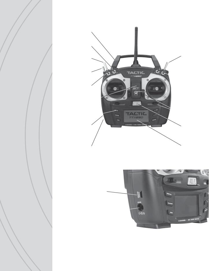
Carrying
Handle
Switch B
Switch F
Switch E
Switch A
LED Power 
Indicator
Pushbuttons 
Firmware
Upgrade
Jack
Charge Jack
Firmware
Upgrade
Jack
Charge Jack 
 Antenna
Switch H
 Switch C
 Switch D


 Neck Strap
Eyelet
 Trim Levers
Power
Switch
LCD
4

SLT TECHNOLOGY, Tx-R,
AND COMPATIBLE RECEIVERS
Tactic’s custom SLT technology ensures that transmitters emit a strong, clear, frequencyhopping 2.4GHz signal, and that your compatible receiver accepts no signal except yours.
Binding Tactic brand receivers is as simple as pushing a button,
™which creates a locked-in, interference free link. The TTX650 radio can store up to 20 models in memory, making it perfect


 to control a full fleet of models with the super-affordable Tactic brand 2.4GHz receivers.The TTX650 is also compatible with non-Tactic brand receivers which use the *SLT protocol, for the ultimate in convenience and fl exibility.
* Make sure optional receivers have the genuine SLT protocol before use with the TTX650.
|
TM |
The TTX650 is also compatible with all transmitter-ready |
|
|
|
|
|
aircraft bearing the “Tx-R” logo. Such aircraft include |
|
|
receivers having the SLT protocol. |
|
|
|
|
|
RECEIVER INSTALLATION
Always mount the optional receiver, servos, switch harness, battery, electronic speed control, etc. as explained in the manual included with such equipment and/or the model. Keep the Rx and its antenna(s) as far away from the engine/motor, servos, and ESC and other electronic items as much as possible. It may also be a good idea to mount the Rx inside certain models using Velcro,® and wrap it in foam rubber to prevent damage from strong vibrations or crash damage (except in extremely warm environments). It’s best to have as few items surrounding the receiver’s antenna tips as possible inside the model, to allow for the most obstruction-free signal path to the transmitter. Exposing the receiver’s antenna tip outside the model is recommended if possible. For receivers with two antennas, position the antennas at 90 degree angles with the tips resting at least 5 inches apart. If possible, allow one antenna to point vertically above the receiver itself.
TTX650 POWER SYSTEM
INPUT POWER
Four 1.5V “AA” alkaline cells (included) or 1.2V “AA” NiCd or NiMH cells supply power to the TTX650. Do not mix cell types, or old and new cells, etc. Slide open the battery door to fi nd the four “AA” cell battery holder. Insert all cells with the proper polarity as shown inside the battery holder. Carefully tuck the wires and battery holder inside the battery compartment so not to damage them when closing the battery door.
Alternatively, an assembled 4.8V NiCd or NiMH “AA” fl at pack can be installed. Remove |
5 |
the alkaline cell holder from the battery compartment and carefully observe the polarity |
|
|

of the wires before disconnecting the plug from the Tx. Install the NiCd or NiMH battery by fi rst inserting its connector into the jack in the battery compartment.
Battery voltage is shown on the LCD’s home screen for easy monitoring. A “LOW BATTERY” warning will show when battery power drops to the voltage value shown in the BATTERY ALARM screen as described on page 12.
WARNING! Never operate an R/C model with weakTx batteries! Reduced operational range and/or possible loss of control of the aircraft could result. Never mix used and new alkaline batteries. Replace weak alkaline batteries, or re-charge NiCd or NiMH batteries before attempting a flight!
A “Tx Batt.” timer in the TIMER menu described on page 28 can track the total amount of time the transmitter has been operational.
See the ACCESSORIES section on page 44 for optional batteries and chargers available at local hobby retailers.
CHARGE JACK AND CHARGING
RECHARGEABLE BATTERIES
The charge jack should only be used for recharging optional NiCd or NiMH batteries (charger not included). Do not try to recharge alkaline batteries.
Charge adapter leads for Futaba® brand transmitters are compatible, with the center pin being positive polarity. The Tx power switch must be in the OFF position to recharge batteries. Do not charge batteries at greater than 1 amp.
Cycling of the Tx batteries can be accomplished through this jack. Misuse, improper charging, or over-charging of rechargeable cells can result in damage to the cells that could include cell rupture, explosion, or fi re!!
WARNING! Do not accidentally short circuit the terminals inside the charge jack, as this can cause permanent damage to the radio’s charge circuitry and battery and void the warranty.
POWER LED
The blue LED illuminates when the power switch is turned on and ample voltage is supplied by the battery. This LED will fl ash if battery voltage drops to the voltage set in the BATTERY ALARM setting described on page 12.
FLIGHT CONTROLS
Channels 1– 6 are fully proportional. Channels 5 and 6 can be controlled by a nonproportional switch or mixed to channels 1– 4 for full proportional control.
Aircraft control is accomplished through various electro-mechanical devices which are manipulated by the pilot, such as the control sticks and toggle switches. In addition, the Tx can automatically manipulate the pilot’s control inputs electronically to alter the control
6 |
signals before they are delivered to the receiver (e.g. mixing two channels, applying |
|

differential reduction to a channel, etc.). Some electronic functions can be turned on/off by the pilot during fl ight such as a timer. Other functions should only be altered while the model is on the ground, such as changing travel limits or reversing for a particular channel.
GIMBAL STICKS
Ball-bearing construction allows both sticks to provide the ultimate in smooth, precise control. Stick length can be adjusted for optimum feel and control. Each stick consists of a base and a tip. To adjust, hold the base tightly, then loosen the tip by turning it counter-clockwise. Adjust the stick tip to the desired length. Tighten the stick by holding the tip in place and turning the base counter-clockwise until it’s tight against the tip.
STICK TENSION AND
THROTTLE RATCHET
Each control stick can be adjusted for softer or stiffer movement tension. A ratchet is also included for the throttle stick which can be adjusted for feel depending on personal preference. Adjustment of either feature requires removal of the rear of the Tx case as explained in the CASE SEPARATION AND ASSEMBLY section below.
CASE SEPARATION AND ASSEMBLY
WARNING! Failure to follow these instructions for separating and re-assembling the Tx case can result in permanent damage to the transmitter, and void the warranty. Contact Hobby Services if you do not feel comfortable that you can safely and accurately perform these steps.
ALWAYS disconnect and remove the batteries from the battery compartment FIRST. Failure to do so can result in permanent damage to the Tx.
Remove the six screws from the back of the Tx case. Carefully pull the case rear away from the case front and note exactly how all wires are routed inside the case.
After adjustments are made as described in other sections of this manual, close the case by fi rst carefully tucking all cables back inside as when the case was opened. Align the case rear back onto the case front, making sure that no wires are pinched between the case parts. Press the case halves together. Insert the screws back into their positions and carefully tighten them until snug - making sure not to cross the threads or over-tighten the screws. Re-connect the battery holder’s connector to the socket inside the Tx. Insert the battery into the compartment, and carefully tuck the wires inside the cavity so they do not become pinched when the door is closed. Close the battery door.
7
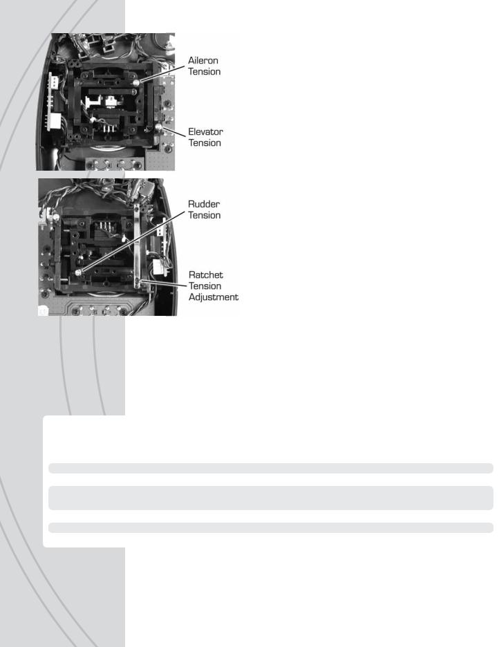
●StickTension: Silver screws on the back of each gimbal are used to adjust the stick tension, as shown at left. Turn the screw clockwise to make stick tension more fi rm. Turn the screw counter-clockwise to make stick tension more light.
●Throttle Ratchet: A silver ratchet bar is mounted across the throttle gimbal. For airplane use, a more firm ratchet feel might be desired for the throttle. In this case, turn the adjustment screw clockwise. For helicopter use, less of a ratchet feel might be desired. Turn this adjustment screw counter-clockwise to achieve the desired feel.
DIGITAL STICK TRIMS
The trim controls for the four main channels are digital. Holding the trim lever will cause the servo output to move repeatedly. Trim positions are visible on the LCD’s home screen, and stored into that respective memory. Changing the model memory will also cause trim settings to change accordingly.
For aircraft with glow engines, the precise position of the trim lever is helpful when determining the engine’s preferred idle point. When the main throttle stick is above 50% full throttle, it will not be possible to trim the throtle servo – even though the indicator on the LCD will move.
The amount of servo movement for each increment of a digital trim can be adjusted as desired, as explained in the TRIM SETTING section on page 18.
TOGGLE SWITCHES
Each switch can be assigned to control one of a variety of functions as desired and described throughout this manual. See page 4 for the location of all switches, which are also marked on the Tx by letter. The factory default switch assignments are as follows:
Switch |
Type |
Default Function |
Default Function |
Airplane |
Helicopters |
||
A |
2-position |
Ch2 Elevator Dual-rate |
Timer Control |
B |
2-position |
(No Setting) |
Gyro Gain |
C |
3-position |
(No Setting) |
(No Setting) |
D |
2-position |
Ch1 Aileron Dual-rate |
Aileron, Elevator, and Rudder |
|
|
|
Dual-rates (All) |
E |
3-position |
Ch4 Rudder Dual-rate |
Normal/Idle-up Control |
F |
2-position, Momentary |
Trainer |
Throttle Cut |
H |
2-position |
Throttle Cut |
Throttle Hold |
ANTENNA
|
The strongest signals are emitted at a 45 degree angle from the sides of the antenna. |
|
8 |
Rotate and fold the antenna so that it’s not pointing directly towards the model during |
|
fl ight. Do not grab the antenna during operation as it may affect radio signal quality. |
||
|
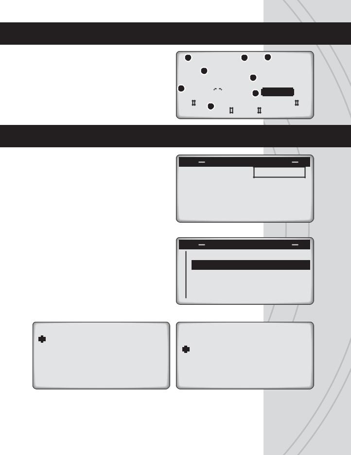
HOME SCREEN
The factory default screen and menus will be for airplanes. |
1 |
01>NAME 2 |
3 |
5.3V |
|
|
|
||||||||||||||||||||||||
|
|
|
|
|
|
|
|
|
|
|
|
|
|
|
|
|
|
|
|
|
|
|
|
|
|
||||||
See the next section for navigating and changing menus for |
|
|
|
|
|
|
|
|
|
|
|
|
|
|
|
|
|
|
|
|
|
|
|
|
|
|
|||||
|
|
|
|
|
|
|
|
|
|
|
|
|
|
|
|
|
|
|
|
|
|
|
|
|
|
|
|
||||
model type and other functions. |
|
|
|
|
|
4 |
|
|
|
|
|
|
|
|
|
|
|
5 |
O |
|
OO |
|
|
|
|||||||
|
|
|
|
|
|
|
|
|
|
|
|
|
|
|
|
|
|
|
|
||||||||||||
1. |
Memory Number |
5. |
Timer |
|
|
|
|
|
|
|
|
|
|
|
|
|
|
|
|
|
|
|
|
|
|
|
|||||
6 |
|
|
|
|
|
|
|
|
|
|
|
|
|
|
|
|
|
|
|
RF-ON |
|
|
|
||||||||
2. |
Model Name |
6. |
Trim Indicators |
|
|
|
|
|
|
|
|
|
|
|
|
|
|
|
|
|
7 |
|
|
|
|
||||||
|
|
|
|
|
|
|
|
|
|
|
|
|
|
|
|
|
|
|
|||||||||||||
|
|
|
|
|
|
|
|
|
|
|
|
|
|
|
|
|
|
|
|
|
|
|
|||||||||
3. |
Battery Voltage |
7. |
Signal Status |
|
|
|
|
|
|
|
|
|
|
|
|
|
|
|
|
|
|
|
|
|
|
||||||
|
|
|
|
|
|
|
|
|
|
|
|
|
|
|
|
|
|
|
|
|
|
|
|
|
|
|
|
||||
4. |
Model Type |
|
|
|
|
|
|
|
|
|
|
6 |
|
|
|
|
|
|
|
|
|
|
|
|
|
|
|
|
|
||
|
|
|
|
|
|
|
|
|
|
|
|
|
|
|
|
|
|
|
|
|
|
|
|
|
|
|
|
|
|
|
|
|
|
|
|
|
|
|
|
|
|
|
|
|
|
|
|
|
|
|
|
|
|
|
|
|
|
|
|
|
|
|
|
MENUS
The TTX650 has three types of menus.
The SYSTEM SETUP menu allows for setting basic operational functions for the radio itself.
SYSTEM SETUP
USER NAME : TACTIC STICK MODE: MODE2 CONTRAST : 0 BEEP VOL. : 0 BATT.ALARM: 4.8v
Selecting and managing the model memories, confi guring the radio for the structure of the airplane or helicopter, etc. is done in the MODEL SETUP menu. Most functions apply for both airplanes and helicopters. Select functions are available for airplanes only or helicopters only.
MODEL SETUP MODEL SELECT
 MODEL MANAGEMENT SWASH TYPE
CHANNEL ASSIGNMENTS WARNINGS
|
|
|
|
SETTINGS |
|
|
|
|
|
|
|
SETTINGS |
|
|
|
|
|
|
|
|
|
|
|
|
|
|
|
||||
|
|
|
|
|
|
|
|
|
|
|
|
|
|
|
|
|
|
SERVO SET |
|
|
|
SERVO |
SET |
||||||||
|
|
DUAL, EXPO |
|
|
|
DUAL, |
EXPO |
||||||||
|
|
CH5 AND CH6 SET |
|
|
|
CH5 AND CH6 SET |
|||||||||
|
|
THROTTLE CURVE |
|
|
|
THROTTLE CUT |
|||||||||
|
|
THROTTLE CUT |
|
|
|
THROTTLE HOLD |
|||||||||
|
|
|
|
|
|||||||||||
Setting various radio functions to control the model is done in the SETTINGS menu. |
|
Some settings apply for both airplanes and helicopters. Select settings are available for |
9 |
airplanes only or helicopters only. |
|
|

LCD, PROGRAMMING CONTROLS, MENU NAVIGATION
The LCD contrast is adjustable for optimum viewing. Six pushbuttons navigate the menus and settings. Single button pushes will result in a single incremental adjustment on-screen. Holding a button for a short time will result in slow scrolling of adjustments; continued holding will result in fast adjustments.
1AILE
2ELEV
3THRO
4RUDD
5AUX1
6AUX2
0%
0%
0%
0%
0%
0%
1AILE
2ELEV
3THRO
4RUDD
5GYRO
6PITC
- -


0%
0%
58%
0%
0%
58%
Left side buttons:
Press any time to see the servo position screen shown above. Indicators for certain channels will change depending on model type, wing type, etc. Moving any Tx control will graphically be shown on this screen. When setting / adjusting mixes to determine if the mix is as desired, set the mix and then view this screen. Move all controls to determine if the mix moves each respective channel as needed.
Quickly resets certain values and settings back to factory defaults. Press to backspace in the model and user name screens.
Jumps back to the previous screen, and removes certain pop-up messages from the screen.
Right side buttons: adjustment of values on-screen
Moves the cursor up, and for increasing highlighted values/settings.
 Moves the cursor down, and for decreasing highlighted values/settings.
 To select or de-select a setting, or enter a screen. Press briefl y to access the SETTINGS menu. Press and hold to access the MODEL SETUP menu.
10
SYSTEM SETUP
Fundamental settings for the transmitter are located in this menu. With the power switch in the OFF position, press and hold ENTER, turn the power switch ON and wait for the SYSTEM SETUP screen to show. Move the cursor and press ENTER to select any setting. Press 
 or
or 
 to change settings. Press ENTER to confi rm the setting.
SYSTEM SETUP
USER NAME : TACTIC STICK MODE: MODE2 CONTRAST : 0 BEEP VOL. : 0 BATT.ALARM: 4.8v
|
USER NAME |
USER NAME |
||||||||||||||
|
USER: |
|||||||||||||||
|
|
|
|
|
|
|
|
|
|
|
|
|
|
Enter your name to identify the |
||
|
|
|
|
|
|
|
|
|
|
|
|
|
|
|||
|
|
|
|
|
|
|
|
ABCDEFGHIJKLMNOP |
radio. The cursor will be under the |
|||||||
|
|
|
|
|
|
|
|
|||||||||
|
|
|
|
|||||||||||||
|
|
|
|
|||||||||||||
|
QRSTUVWXYZabcdefghi |
fi rst character to enter. Press |
||||||||||||||
|
or |
|
to fi nd the desired character, |
|||||||||||||
|
jklmnopqrstuvwxyz01 |
|
||||||||||||||
|
then ENTER to confi rm. The cursor |
|||||||||||||||
|
|
|
|
|
|
|
|
|
|
|
|
|
|
will automatically move to the next |
||
character. Selecting  or
or  can move the cursor freely. Repeat as necessary for up to 8 characters. Pressing CLEAR will move the cursor back one space and erase the character in that space. Press ESC when fi nished.
STICK MODE
The TTX650 is factory set to Mode 2 confi guration, but can be changed to Mode 1 (elevator on left, throttle on right). To change modes in the programming, move the cursor to the STICK MODE line, highlight and press ENTER, then press 
 or
or 
 . Press ENTER to confi rm.
NORMAL STICK CONFIGURATIONS
LEFT |
RIGHT |
STICK |
STICK |
Rudder |
Aileron |
Mode1: Elevator |
Mode1: Throttle |
Mode2: Throttle |
Mode2: Elevator |
In addition to programming changes, stick mode changes require reversal of the throttle ratchet and elevator arm/spring. Refer to the CASE SEPARATION AND ASSEMBLY section on page 7 for opening and safely re-assembling the case after the mechanical adjustments are made. Failure to do this properly can cause permanent damage to the radio and void the warranty.
Throttle Ratchet: The long metal bar resting across the throttle gimbal must be moved to the other gimbal. Carefully remove the screws at each end of the bar. Re-locate the bar to the other gimbal and install across the ratcheted surface of the gimbal. Re-install both screws. Carefully install the screw at top until snug – do not over-tighten! The screw at bottom should be tightened until the vertical movement of this stick has the
desired amount of resistance. |
11 |
|
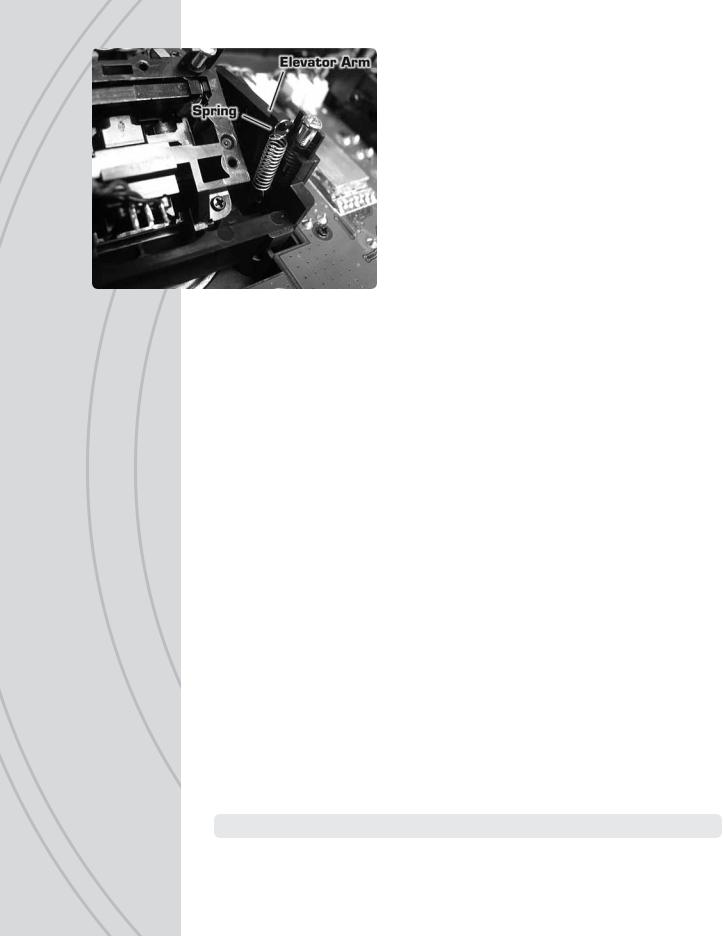
Elevator arm and spring: The black plastic arm and spring must be re-located from the elevator gimbal to the opposite gimbal. Using a pair of needle nose pliers or hemostats, carefully grip the end of the spring which is looped over the end of the black plastic arm and gently lift it off the arm. Then slide the spring towards the center of the gimbal to remove it from the gimbal. Set the spring aside.
Raise the plastic arm to a vertical position. Slide the arm towards the center of the gimbal to remove it from its mounting pin.
Rotate the arm 180 degrees to mount it to the opposite gimbal.While in the vertical position, slide the arm over the mounting pin on the opposite gimbal. Lay the arm down across the gimbal.
Gripping one loop on the end of the spring with pliers or hemostat, carefully lower the opposite loop of the spring into the gimbal to slide it over the appropriate mounting pin. With the spring holding onto the pin inside the gimbal, carefully stretch the spring and hook the loop over the end of the plastic arm. Confi rm the arm and spring are mounted properly by moving this stick and ensuring all movement is smooth but with resistance from the spring.
Close the transmitter as explained in the CASE SEPARATION AND ASSEMBLY section.
CONTRAST
Adjust the LCD’s contrast level for optimum viewing.
BEEP VOLUME
Adjust the loudness of the radio’s beeper as desired. This volume setting affects all tones that are emitted from the radio including while making adjustments such as trim adjustments, programming changes, etc. Beep volume for all alarms is not adjustable.
BATTERY ALARM
An alarm will sound and the display will show “LOW BATTERY” when the Tx battery’s voltage drops to the level shown in this setting. Do NOT set this value too low, as the radio could lose power very rapidly as the battery nears full discharge and cause a loss of control of the model. Land the model immediately once this alarm has sounded!
Battery type |
Default Recommended Minimum |
Nickel-Cadmium (NiCd) or Nickel-Metal Hydride (NiMH)
Alkaline
4.00V |
4.40V |
4.00V |
4.00V |
4.00V |
3.60V |
Once all functions in this menu are set, press ESC to return to the home screen.
12
MODEL SETUP MENU – AIRPLANES
From the home screen, press and hold ENTER for 2 seconds to fi nd the MODEL SETUP menu which is for setting of fundamental operating parameters as shown here.
MODEL SELECT
MODEL SETUP MODEL SELECT
 MODEL MANAGEMENT WING TYPE
CHANNEL ASSIGNMENTS WARNINGS
Memories are available to store parameters for up to 20 different models. This screen is for selecting the model to be active. Move the cursor to fi nd the desired model to make active, and press ENTER. You will be forced to select a model type (airplane or heli). The radio will automatically return to the home screen.
Changing the model memory is not possible if the Tx battery voltage is too low. See the INPUT POWER section on page 5. It’s a good idea to keep a record of all settings for each memory as a backup in case parameters in a particular memory are accidentally changed, etc.
MODEL
SELECT
MODEL MANAGEMENT
01: GeeBee
02:
 Axe100
03: Extra
Extra
04: Cirrus
05:
 Novus
Novus
06: Yak-54
Mode1 Management[01]
Type:  Airplane
Name: GeeBee
Copy
Reset
Erase
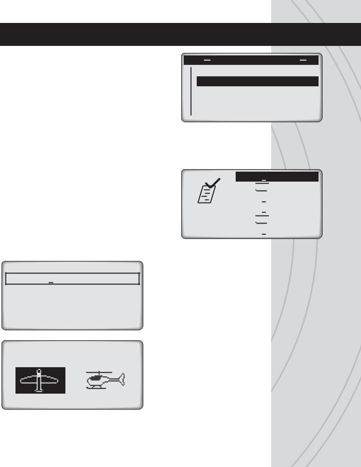
MODEL TYPE
Shows basic information regarding the model setup in the memory number shown at top in brackets. Move the cursor up or down to select / change the function to adjust, and press ENTER to enter the function screen.
Type: Press 
 or
or 
 to select the model type as airplane or helicopter. Press ENTER to confi rm.
AIRPLANE HELICOPTER
Name: Move the cursor to this line and press ENTER. The method for setting the |
|
model name is the same as for entering the USER NAME as described on page 11. The |
13 |
maximum number of characters is six. Press ESC when fi nished. |

Copy: To copy all parameters from one model memory to another, place the cursor over “Copy” and press ENTER. The “COPY FROM” page will show. Highlight the memory to copy FROM and press ENTER. Now the “COPY TO” page will show.
COPY FROM
01: GeeBee
02:
 Axe100
03: Extra
Extra
04: Cirrus
05:
 Novus
Novus
06: Yak-54
COPY
TO
01: GeeBee
02:
 Axe100
03: Extra
Extra
04: Cirrus
05:
 Novus
Novus
06: Yak-54
Place the cursor over the memory number to copy TO, and press ENTER.The confirmation screen will show.
To NOT proceed with the copy function as shown on-screen, highlight “NO” and press ENTER to cancel and return to the main MODEL MANAGEMENT screen.
01: GeeBee
03: Extra
Extra
CONTINUE? NO YES
Otherwise, press 
 to highlight “YES” and press ENTER. All settings that previously existed in the receiving memory will be permanently erased. The display will return to the main MODEL MANAGEMENT screen. Return to the MODEL SELECT screen to confi rm the copy function was successful by looking at the memory that was copied “to”.
MODEL RESET
01: GeeBee
02:
 Axe100
03: Extra
Extra
04: Cirrus
05:
 Novus
Novus
06: Yak-54
Reset: To change the parameters of any single memory except model type and model name use this reset function. Enter this screen, move the cursor over the memory to reset and press ENTER. Select “NO” to cancel or “YES” to proceed with the reset, and press ENTER.
05:
 Novus
Novus
CONTINUE? NO YES
Erase: Use the erase function to completely clear all settings in any single memory to factory default settings.The method for selecting, cancelling, and approving this function is the same as for reset. You will be forced to select a model type before proceeding (airplane or helicopter).
14

WING TYPE
This is for setting the type of tail and wing confi guration for the model. Depending on the mixes used and setup of the aircraft, it might be necessary to change the aileron, elevator, or rudder reversing settings to achieve the proper throw directions for the model.
FLAP |
1AI |
TAIL |
Normal |
FLAP SETTINGS
The “FLAP” setting allows for confi guration of the ailerons and/or fl aps of the airplane. Move the cursor over “1AI” to select from the following options:
1AI: Use this “1 aileron” setting for normal wing types having one aileron on each wing, where by utilizing a Y-harness one servo input controls the movements of both servos simultaneously.
1AI1FL: This “1 aileron + 1 flap” setting is for wings having one servo that controls the ailerons on both wings, and another servo (or 2 servos on a Y-harness) that controls the fl aps on both wings (both servos moving in the same direction). Connect the aileron servo to Rx channel 1, and the flap servo to channel 5. (Not available for delta.)
2AI: This “2 ailerons” setting is for airplanes having one aileron servo for each wing. Connect one aileron servo to Rx channel 1, and the other to channel 6. This setting allows each aileron servo to function independently of the other.
2AI1FL: This “2 ailerons + 1 fl ap” setting is for airplanes having two separate aileron servos, requiring one servo to control each aileron, and also one servo (or 2 servos on a Y-harness) that will control fl aps for both wings simultaneously. (Not available for 2 elev tail settings.)
TAIL SETTINGS
“Normal” is the factory default setting for the “TAIL” type. Move the cursor over “Normal”, press ENTER then
 or
or
 to select from V-Tail, Delta (elevon), and 2 Elevator options. Press ENTER to confi rm the selection. The charts below can aid in determining the preferred tail and fl ap setting for the model.
Airplane - Normal Tail
|
|
1AIL/ |
|
2AIL/ |
|
1AIL |
1FLAP |
2AIL |
1FLAP |
CH1 |
AIL |
AIL |
AIL |
AIL |
CH2 |
ELEV |
ELEV |
ELEV |
ELEV |
CH3 |
THRO |
THRO |
THRO |
THRO |
CH4 |
RUDD |
RUDD |
RUDD |
RUDD |
CH5 |
AUX1 |
FLAP |
AUX1 |
FLAP |
CH6 |
AUX2 |
AUX2 |
AIL2 |
AIL2 |
Normal: One servo each is used for aileron(s), elevator(s), and rudder.
15
 Loading...