

Page 1

Page 2

TABLE OF CONTENTS
FEATURES. . . . . . . . . . . . . . . . . . . . . . . . . . . . . . . . . . . . . . . . . . . . . . . . . . . . . . . . . . . . . . . . . . . . . . . . . 3
SLT TECHNOLOGY, Tx-R, AND COMPATIBLE RECEIVERS . . . . . . . . . . . . . . . . . . . . . . . . . . . . . . . . . . 3
TTX610 TRANSMITTER. . . . . . . . . . . . . . . . . . . . . . . . . . . . . . . . . . . . . . . . . . . . . . . . . . . . . . . . . . . . . . . 4
Input Power . . . . . . . . . . . . . . . . . . . . . . . . . . . . . . . . . . . . . . . . . . . . . . . . . . . . . . . . . . . . . . . . . . . . . 4
Power Switch, LED, and Low Battery Alarm . . . . . . . . . . . . . . . . . . . . . . . . . . . . . . . . . . . . . . . . . . . . 4
Charge Jack and Charging Rechargeable Batteries . . . . . . . . . . . . . . . . . . . . . . . . . . . . . . . . . . . . . . 4
FLIGHT CONTROLS . . . . . . . . . . . . . . . . . . . . . . . . . . . . . . . . . . . . . . . . . . . . . . . . . . . . . . . . . . . . . . . . . 5
Gimbal Sticks . . . . . . . . . . . . . . . . . . . . . . . . . . . . . . . . . . . . . . . . . . . . . . . . . . . . . . . . . . . . . . . . . . . . 5
Aileron . . . . . . . . . . . . . . . . . . . . . . . . . . . . . . . . . . . . . . . . . . . . . . . . . . . . . . . . . . . . . . . . . . . . . . . . . 5
Elevator . . . . . . . . . . . . . . . . . . . . . . . . . . . . . . . . . . . . . . . . . . . . . . . . . . . . . . . . . . . . . . . . . . . . . . . . 5
Throttle. . . . . . . . . . . . . . . . . . . . . . . . . . . . . . . . . . . . . . . . . . . . . . . . . . . . . . . . . . . . . . . . . . . . . . . . . 5
Rudder . . . . . . . . . . . . . . . . . . . . . . . . . . . . . . . . . . . . . . . . . . . . . . . . . . . . . . . . . . . . . . . . . . . . . . . . . 5
Channel 5 . . . . . . . . . . . . . . . . . . . . . . . . . . . . . . . . . . . . . . . . . . . . . . . . . . . . . . . . . . . . . . . . . . . . . . 5
Channel 6. . . . . . . . . . . . . . . . . . . . . . . . . . . . . . . . . . . . . . . . . . . . . . . . . . . . . . . . . . . . . . . . . . . . . . . 6
Digital Trims . . . . . . . . . . . . . . . . . . . . . . . . . . . . . . . . . . . . . . . . . . . . . . . . . . . . . . . . . . . . . . . . . . . . . 6
Reversing Switches . . . . . . . . . . . . . . . . . . . . . . . . . . . . . . . . . . . . . . . . . . . . . . . . . . . . . . . . . . . . . . . 6
TRAINER FUNCTION. . . . . . . . . . . . . . . . . . . . . . . . . . . . . . . . . . . . . . . . . . . . . . . . . . . . . . . . . . . . . . . . . 7
Wired Trainer . . . . . . . . . . . . . . . . . . . . . . . . . . . . . . . . . . . . . . . . . . . . . . . . . . . . . . . . . . . . . . . . . . . . 7
Wireless Trainer . . . . . . . . . . . . . . . . . . . . . . . . . . . . . . . . . . . . . . . . . . . . . . . . . . . . . . . . . . . . . . . . . . 7
ELEVON AND V-TAIL MIXING . . . . . . . . . . . . . . . . . . . . . . . . . . . . . . . . . . . . . . . . . . . . . . . . . . . . . . . . . . 8
STABILIZATION AND RECOVERY . . . . . . . . . . . . . . . . . . . . . . . . . . . . . . . . . . . . . . . . . . . . . . . . . . . . . . 8
RECEIVER AND FLIGHT EQUIPMENT INSTALLATION. . . . . . . . . . . . . . . . . . . . . . . . . . . . . . . . . . . . . . 9
Receiver. . . . . . . . . . . . . . . . . . . . . . . . . . . . . . . . . . . . . . . . . . . . . . . . . . . . . . . . . . . . . . . . . . . . . . . . 9
Servos . . . . . . . . . . . . . . . . . . . . . . . . . . . . . . . . . . . . . . . . . . . . . . . . . . . . . . . . . . . . . . . . . . . . . . . . . 9
ELECTRIC AND COMBUSTION POWERED APPLICATIONS . . . . . . . . . . . . . . . . . . . . . . . . . . . . . . . . . 9
Electric Models. . . . . . . . . . . . . . . . . . . . . . . . . . . . . . . . . . . . . . . . . . . . . . . . . . . . . . . . . . . . . . . . . . . 9
Combustion Models . . . . . . . . . . . . . . . . . . . . . . . . . . . . . . . . . . . . . . . . . . . . . . . . . . . . . . . . . . . . . . 10
LINK THE RECEIVER TO THE TRANSMITTER . . . . . . . . . . . . . . . . . . . . . . . . . . . . . . . . . . . . . . . . . . . 10
FAILSAFE FUNCTION . . . . . . . . . . . . . . . . . . . . . . . . . . . . . . . . . . . . . . . . . . . . . . . . . . . . . . . . . . . . . . . 10
SYSTEM CHECK AND OPERATION. . . . . . . . . . . . . . . . . . . . . . . . . . . . . . . . . . . . . . . . . . . . . . . . . . . . 11
FLYING THE AIRCRAFT . . . . . . . . . . . . . . . . . . . . . . . . . . . . . . . . . . . . . . . . . . . . . . . . . . . . . . . . . . . . . 11
SAFETY GUIDE . . . . . . . . . . . . . . . . . . . . . . . . . . . . . . . . . . . . . . . . . . . . . . . . . . . . . . . . . . . . . . . . . . . . 12
SERVOS AND ACCESSORIES . . . . . . . . . . . . . . . . . . . . . . . . . . . . . . . . . . . . . . . . . . . . . . . . . . . . . . . . 12
SPECIFICATIONS . . . . . . . . . . . . . . . . . . . . . . . . . . . . . . . . . . . . . . . . . . . . . . . . . . . . . . . . . . . . . . . . . . 12
TTX610 Transmitter . . . . . . . . . . . . . . . . . . . . . . . . . . . . . . . . . . . . . . . . . . . . . . . . . . . . . . . . . . . . . . 12
TR625 Receiver . . . . . . . . . . . . . . . . . . . . . . . . . . . . . . . . . . . . . . . . . . . . . . . . . . . . . . . . . . . . . . . . . 12
Other Items Included . . . . . . . . . . . . . . . . . . . . . . . . . . . . . . . . . . . . . . . . . . . . . . . . . . . . . . . . . . . . . 12
IMPORTANT WARNINGS AND PRECAUTIONS. . . . . . . . . . . . . . . . . . . . . . . . . . . . . . . . . . . . . . . . . . . 13
TROUBLESHOOTING . . . . . . . . . . . . . . . . . . . . . . . . . . . . . . . . . . . . . . . . . . . . . . . . . . . . . . . . . . . . . . . 13
CE COMPLIANCE INFORMATION FOR THE EUROPEAN UNION . . . . . . . . . . . . . . . . . . . . . . . . . . . . 14
INDUSTRY CANADA NOTICE. . . . . . . . . . . . . . . . . . . . . . . . . . . . . . . . . . . . . . . . . . . . . . . . . . . . . . . . . 14
FCC STATEMENT . . . . . . . . . . . . . . . . . . . . . . . . . . . . . . . . . . . . . . . . . . . . . . . . . . . . . . . . . . . . . . . . . . 15
WARRANTY INFORMATION . . . . . . . . . . . . . . . . . . . . . . . . . . . . . . . . . . . . . . . . . . . . . . . . . . . . . . . . . . 15
2
Page 3
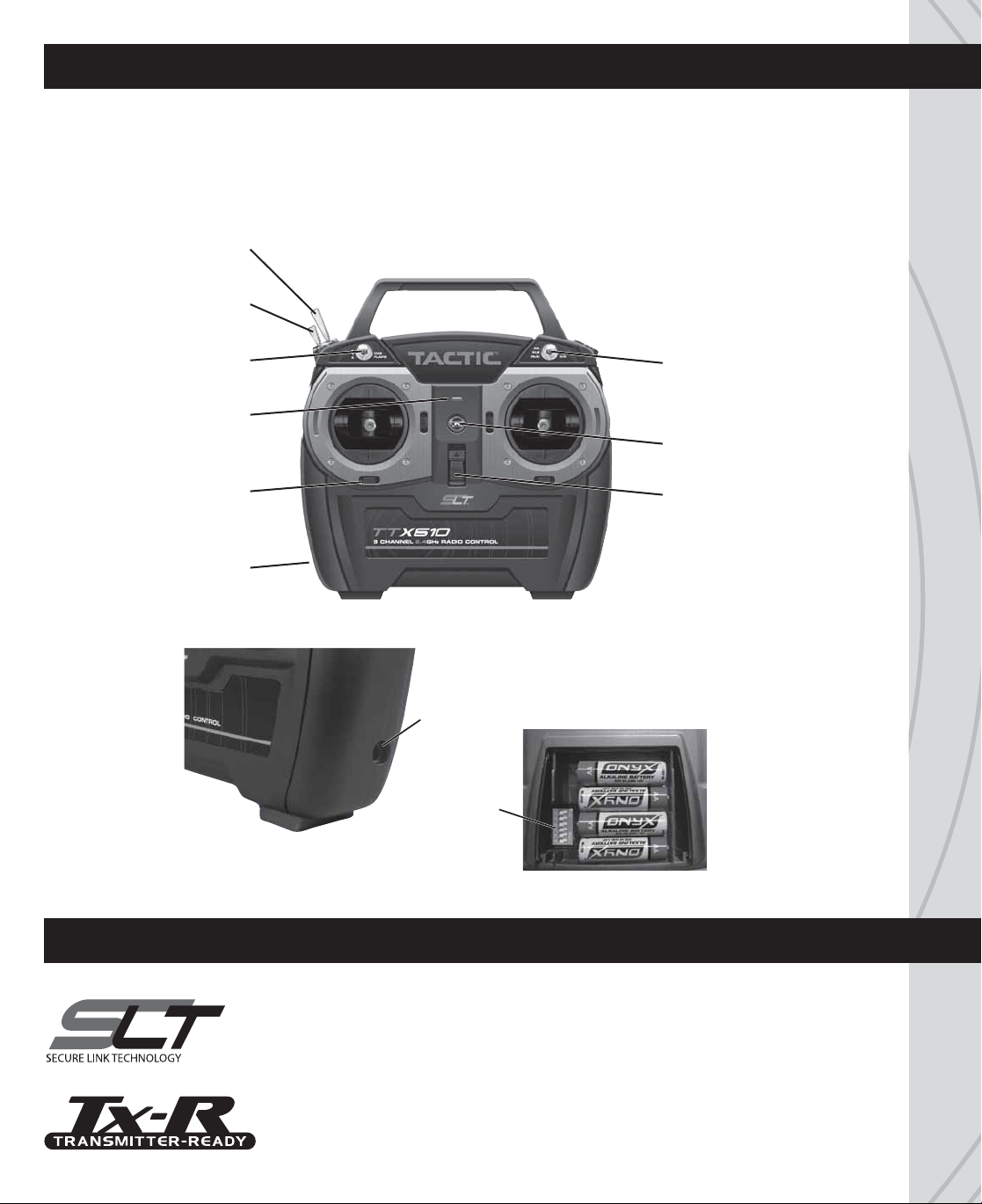
FEATURES
● Ball-bearing gimbals ● Charge jack for optional rechargeable batteries
● Digital trims ● Failsafe function in the tiny Tactic 6 channel receiver
● Power LED with low voltage warning ● Wired and wireless trainer functions
Trainer
Switch
Channel 5
Switch
Channel 6
Switch
LED Power
Indicator
Trim Lever
Trainer Jack
(rear)
Dual Rate
Switch
Neck Strap
Eyelet
Power
Switch
Charge Jack
Reversing
Switches
Battery Compartment
SLT TECHNOLOGY, Tx-R, AND COMPATIBLE RECEIVERS
The SLT technology ensures that transmitters emit a strong, clear, frequency-
hopping 2.4GHz signal, and that your compatible receiver accepts only your signal.
™
Binding most Tactic brand receivers is as simple as pushing a button. The TTX610
is also compatible with all transmitter-ready aircraft bearing the Tx-R™ logo, and
non-Tactic brand receivers having the SLT protocol*.
TM
* Make sure optional receivers have the genuine SLT protocol before use with the TTX610.
3
Page 4
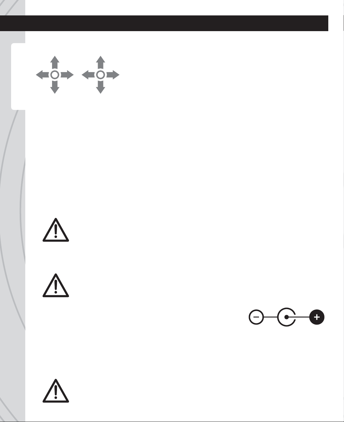
TTX610 TRANSMITTER (Tx)
LEFT
STICK
Rudder
Mode1: Elevator
Mode2: Throttle
Mode1: Throttle
Mode2: Elevator
Aileron
RIGHT
STICK
NORMAL STICK CONFIGURATIONS
TTX610 Charge Jack
INPUT POWER
Four 1.5V “AA” alkaline batteries or 1.2V rechargeable nickel-cadmium (NiCd) or nickel-metal hydride (NiMH)
batteries are required (not included). Do not mix cell types, or old and new cells, etc. See the SERVOS AND
ACCESSORIES section on page 12 for optional batteries available at local hobby retailers. Slide open the
battery door. Insert all cells with the proper polarity as shown inside the battery holder. Close the battery door.
POWER SWITCH, LED, AND LOW BATTERY ALARM
The red LED should light when the power switch is moved upwards to the “ON” position. The Tx should have
adequate power for flight when the LED is on constantly. Flashing of this LED accompanied by beeps means
the Tx batteries have weakened and operation of the model should NOT be attempted!
The TTX610 is available in either a “Mode 2” configuration with
throttle on the left and elevator on the right, or “Mode 1” configuration
with throttle on the right and elevator on the left. Be sure the radio
purchased is of the correct mode.
To change between stick modes (mode2 <> mode1), see www.
tacticrc.com/transmitters and follow the link for the TTX610 radio
to find detailed instructions.
WARNING! Never operate an R/C model with weak Tx batteries! Reduced operational range
and/or possible loss of control of the aircraft could result. Replace weak alkaline batteries,
or re-charge NiCd or NiMH batteries before attempting a flight! If this alarm activates
during flight land the aircraft immediately! Failure to do so could result in destruction of
the model and possibly bodily injury!
CHARGE JACK AND CHARGING RECHARGEABLE BATTERIES
WARNING!! Do NOT attempt to recharge alkaline batteries! The charge jack should ONLY be
used if rechargeable cells are used in the transmitter. Do not accidentally short circuit the terminals
inside the charge jack as permanent damage could result and void the warranty.
The TTX610 includes a built-in charge jack for convenient recharging of
NiCd or NiMH batteries, and is compatible with charge leads designed
for Futaba
This jack is NOT compatible with charge leads for Hitec®, Airtronics®, JR
or Spektrum® radios. Always make sure to use a charger (not included)
which is 100% compatible with the selected battery type.
To use the charge jack, make sure the Tx power switch is in the OFF position. Connect a compatible charge
lead (such as TACP0101) to the charger first, then to the Tx charge jack. Follow the instructions included
with the charger.
®
brand transmitters with the center pin being positive polarity.
WARNING!! Do not charge batteries at currents greater than 1 amp through this charge
jack. Misuse, improper charging, or over-charging of rechargeable cells can result in
damage to the cells that could include cell rupture, explosion, or fire!!
4
®
Page 5
FLIGHT CONTROLS
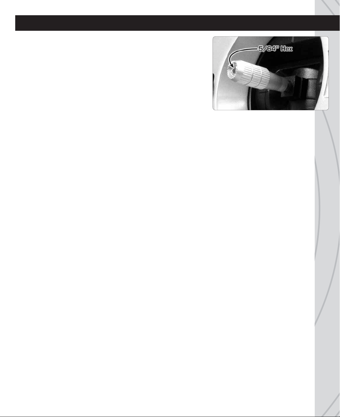
GIMBAL STICKS
Ball-bearing construction allows both sticks to provide the ultimate in
smooth, precise control. Stick length can be adjusted for optimum feel
and control. Using a 5/64 inch hex wrench, loosen the set screw inside
the tip of the stick. Rotate the stick tip counter-clockwise to lengthen or
clockwise to shorten the stick. Once the desired stick length is found,
tighten the set screw.
AILERON (CH1)
Controls the moveable surfaces at the end of both main wings to rotate the airplane about the “roll” axis (an
imaginary line which extends from the airplane’s nose to the tail). The aileron reversing switch must be set so
moving the aileron stick to the right will cause the airplane’s right aileron to deflect up, thus causing the right
wing to drop and the airplane will bank to the right. Moving the aileron stick to the left will cause the airplane’s
left wing to drop and the airplane will bank to the left. This is one important method for turning the aircraft.
ELEVATOR (CH2)
Controls the moveable horizontal surfaces on the airplane’s tail to rotate the airplane about the “pitch” axis
(an imaginary line extending through the center of both main wings, from one wing tip to the other wing tip).
The elevator reversing switch must be set so that pulling the elevator stick back (towards you) will cause
the elevators to deflect up, thus causing the nose of the airplane to rise. Pushing the elevator stick forwards
(away from you) will cause the nose of the airplane to drop. When using the ailerons to bank the airplane’s
wings, pulling the elevator stick back will help the aircraft maintain altitude and turn the aircraft more quickly.
THROTTLE (CH3)
Controls the speed (R.P.M.) at which the engine or electric motor operates. With the throttle reversing switch
in the normal position, pulling the throttle stick back will cause the engine’s speed to decrease. Pushing the
throttle stick forward will cause the engine’s speed to increase.
RUDDER (CH4)
Controls the sideways movement of the airplane’s tail and will rotate the airplane about the “yaw axis” (an
imaginary line from the top of the airplane’s fuselage to the bottom of the fuselage, located near the centerpoint of the fuselage). The rudder reversing switch must be set so that moving the rudder stick to the right
causes the rudder to deflect to the right, thus causing the nose of the airplane to point to the right. Moving the
rudder stick to the left will cause the nose of the airplane to turn left. When using the rudder in conjunction
with the ailerons, the airplane’s nose can point into a turn (instead of pointing up and “skidding” through the
turn), allowing the airplane to perform tighter, more coordinated turns.
CHANNEL 5
This channel offers two-position non-proportional control and is typically used to control retractable landing
gear, controlled by the switch shown on page 3. Rotational servo movement is limited to full clockwise
movement and full counter-clockwise movement.
5
Page 6

CHANNEL 6
This channel offers three-position non-proportional control, and is often used for control of airplane flaps for full up,
center, and full down positions. This switch as shown on page 3 can also be used to change the sensitivity setting
of gyros or other accessory items.
DIGITAL TRIMS
One trim lever is included for each of the four main controls, located adjacent to the respective stick. All trims are
digital in function, and always rest at mechanical center position. Briefly depressing the lever to either side away
from center will cause the respective servo output to finely rotate to one direction. Pressing and holding the trim
lever will cause the servo output to move repeatedly. Ideally during a flight, when the main sticks are released
and spring back to center position the aircraft should not veer in any direction. If the aircraft veers in a particular
direction, click the respective trim lever until the aircraft maintains a straight attitude on its own.
For airplanes with glow engines, the position of the throttle trim lever is helpful for determining the engine’s preferred
idle point. The throttle trim lever is not active when the main throttle stick is above 50% full throttle
.
REVERSING SWITCHES
Inside the battery compartment is a bank of switches, with one reversing switch for each channel. Each
switch can reverse the rotational direction of the servo that is connected to that respective channel. This is
often a much easier method for changing the direction of a servo’s movement as opposed to altering the
mechanical connections between the model’s surface and the servo. Refer to the model’s instructions for
specific details.
The switch bank is numbered 1, 2, 3, 4, 5, and 6 for each respective channel. Moving the small switch lever
for the respective channel number will change the direction of control for that channel.
DUAL RATE SWITCH
The travel distance of the servos for the aileron, elevator, and rudder channels can be changed at any time
by using the switch marked AIL / ELE / RUD D/R, located above the right stick. This switch will change the
travel distance of all three channels at the same time (not separately). With the switch in one position, each
channel’s servo will be capable of rotating through its full travel range (100%). Moving the switch to the
opposite position will limit the rotational range of each channel’s servo to 60% of its maximum rotational
range. Placing the dual-rate switch in one position can allow for better control of the model while on the
ground, at low altitudes, or while performing certain maneuvers. Moving the switch to the opposite position
can allow for optimum control of the aircraft in mid-flight.
6
Page 7

TRAINER FUNCTION
The TTX610 Tx includes both wired and wireless trainer functions.
IMPORTANT!
reverse settings and trim adjustments on the teacher and student transmitters match! Otherwise, the
model could suddenly veer in an unwanted manner when the teacher’s trainer switch is activated.
Proper matching of the student and teacher’s Tx settings should ensure that no unexpected
movements occur when the trainer switch is pressed. This is especially true of the throttle control!
Before flying the model in training situations it’s important to make sure all channel
WIRED TRAINER
This option allows for connection to another Tx having a trainer jack, and can function as either the teacher
or student’s Tx. This also allows for connection of the TTX610 to some computer based flight simulators. See
the SERVOS AND ACCESSORIES section on page 12 for recommended trainer cords. Refer to instructions
included with those cords. To properly assign control of the aircraft to the teacher/student when using two
Tactic brand transmitters for training, follow these steps in order:
1. Link the teacher’s Tx to the receiver inside the aircraft as explained on page 10. Remove power from
the Rx, then the Tx.
2. Connect the student’s Tx to the teacher’s Tx with the appropriate trainer cord.
3. Turn the student’s transmitter power switch ON.
4. Turn the teacher’s transmitter power switch ON.
5. To transfer control of the aircraft to the student, pull the teacher’s trainer switch and hold. Release
the switch to immediately return control of the aircraft to the teacher.
6. When the training session has ended and power has been safely removed from the model, disconnect
the trainer cord.
WIRELESS TRAINER
This option allows for communication with another Tactic Tx by wireless means, and can function as the teacher
or student’s Tx. This function is not compatible with other brand radios.
1. Link the teacher’s Tx to the receiver inside the aircraft. Remove power from the Rx, then the Tx.
2. The student must use a separate Tactic Tx with wireless trainer function.
3.
Place both transmitters within 1 meter of each other, with the throttle stick for each Tx in the idle position.
4. Turn the student’s Tx power switch ON.
5. Pull and hold the teacher’s Tx trainer switch, and then turn the teacher’s Tx power switch ON.
6. The LED on the teacher’s Tx will flash 3 times to indicate it has linked to the student’s Tx.
7. Release the trainer switch on the teacher’s Tx.
8. Once both transmitters are linked together, power can be applied to the Rx to prepare for flight. Make
sure both transmitters are kept within 15 feet of each other at all times while training.
9. To transfer control of the aircraft to the student, pull the teacher’s trainer switch and hold. Release
the switch to immediately return control of the aircraft to the teacher.
10. When the training session has ended and power has been safely removed from the model, turn
OFF the power switch of both transmitters. This will break the wireless link between both transmitters.
Return to step 1 above to re-establish the wireless link for additional training.
7
Page 8

ELEVON and V-TAIL MIXING
Left Rudder
ch2 ch4 ch2 ch4
Right Rudder
ch2 ch4
Up Elevator
Elevator
Function
Aileron
Function
The TTX610 includes elevon and v-tail mixing functions. The default setting for all mixing will be “off”, meaning
functionality will be suitable for traditional airplane wings and a normal T-shaped tail. To change the mix setting:
3.
The LED should flash. If accompanied by two beeps the V-tail mix function has been activated. “V-tail”
is a mixture of the elevator and rudder channels. Two servos are used in the tail; one for each control
surface. This will control the airplane’s “pitch” and “yaw” axis at the same time. If the elevator and rudder
functions appear reversed at the control surfaces it may be necessary to swap the channel 2 and channel
4 servo plug positions in the receiver. If this is the desired mix function move to the next section.
1. With the Tx power switch off, move the right stick to the bottomright corner, the left stick to the bottom-left corner, and hold in
these positions.
2. Turn the Tx power switch ON.
4. To skip the V-tail mix and instead activate the elevon (delta
wing) mixer, turn the Tx power switch OFF and repeat the
above procedure. When the flashing LED is accompanied
by three beeps the elevon mixer will be active. “Elevon” is
a mixture of the elevator and aileron channels and controls
the airplane’s “pitch” and “roll” axis simultaneously. One
servo is used for each control surface. If the elevator and
aileron functions appear reversed at the control
surfaces it may be necessary to swap the
channel 1 and channel 2 servos’ plug positions
at the receiver.
STABILIZATION GYROS
Optional stabilization gyros can be used to help maintain stable control of an airplane during flight. Gyros
can supply feedback to the aileron, elevator, and rudder controls separately. Many gyros also offer the ability
to change the sensitivity of the on-board sensors during flight. By connecting a gyro’s input connector to
receiver channel 6, the TTX610’s channel 6 switch can be used to change between the gyro’s different
sensitivity selections. See the gyro’s instructions for details about all connections and settings.
8
5. To cancel all mixes, repeat this procedure
again. When the flashing LED is accompanied
by one beep all mixes will be off.
Page 9
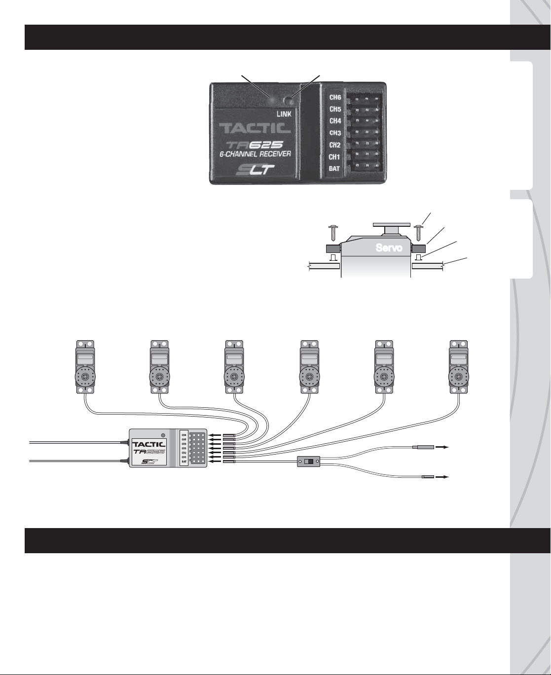
RECEIVER and FLIGHT EQUIPMENT INSTALLATION (if applicable)
CH6 Auxiliary (Flaps)
CH5 Auxiliary (Landing Gear)
CH4 Rudder
CH3 Throttle (ESC or Servo)
CH2 Elevator
CH1 Aileron
BAT Battery
LED Link Button
Rubber Grommet
Brass Eyelet
S
ervoServoServo
Screw
Servo Tray
RECEIVER (Rx)
Mount the Rx as specified in the model’s
instructions. Wrapping the Rx with foam
rubber can help to prevent damage
resulting from vibration but could prevent
adequate airflow from passing over the Rx.
See the SERVOS AND ACCESSORIES
section for additional Tactic receivers.
SERVOS
Center all trims on the Tx. Install the servos in the model and
connect linkages as shown in the model’s instructions. Do NOT
over-tighten the mounting screws, as the servos should be able to
move slightly to compensate for engine vibration. Make sure the
pushrods are not too loose or bind in any way, and use a servo
arm which allows for full range of motion for the servo. This can
be tested by moving the Tx sticks to maximum positions several
times while observing the movement of the control services. Adjust binding servos/linkages to prevent excessive
draining of the battery. Move the Tx trims to finely adjust the servo’s center point as needed for the application.
Connect the servos to the Rx as shown. Route the wires to not interfere with moving parts.
Auxiliary
Servo
(Ch6)
See the SERVOS AND ACCESSORIES section on page 12 for a full list of optional servos.
Auxiliary
Servo
(Ch5)
6-CHANNEL RECEIVER
Receiver
Rudder
Servo
(Ch4)
LINK
Throttle
Servo
or ESC
(Ch3)
Switch Harness
Elevator
Servo
(Ch2)
Aileron
Servo
(Ch1)
To Rx Battery
To Charger
ELECTRIC and COMBUSTION POWERED APPLICATIONS
ELECTRIC MODELS
An optional ESC (electronic speed control) will be necessary to control speed of the electric motor, and
to supply power to the receiver and servos. Connect the ESC’s receiver plug to Rx slot marked CH3 (for
throttle). Center the transmitter’s throttle trim and follow the ESC instructions for proper operation and
connection of the battery.
9
Page 10

COMBUSTION MODELS
Individual “AA” NiCd or NiMH rechargeable batteries can be installed in the included battery holder to power
the flight electronics (do not use alkaline cells). An optional rechargeable battery pack could instead be used.
See the SERVOS AND ACCESSORIES section on page 12 for suggested options. The included switch harness
can conveniently turn power ON/OFF to the flight electronics. Refer to the model’s instructions for the location
to mount the battery, Rx, and switch harness for optimum weight distribution.
IMPORTANT! Apply power to the Tx BEFORE applying power to the Rx, and make sure the Tx
throttle stick is at minimum (idle) position. Failure to do so could result in the model becoming
uncontrollable and cause a safety hazard.
Locate the switch harness away from the propeller and the glow engine exhaust. Cut a hole in the side of
the fuselage large enough to allow the switch’s lever to move fully from end-to-end - but not so long that
the mounting screws cannot be secured to the fuselage. Connect the wire at the “ON” side of the switch to
the receiver’s “BAT” slot. Connect the battery to the appropriate wire at the “OFF” side of the switch. The
remaining wire at the “OFF” side of the switch can be used for re-charging the battery through the switch
harness. Make sure the switch is in the “OFF” position to charge the battery through the switch.
LINK THE RECEIVER TO THE TRANSMITTER
Linking the TTX610 to the included receiver ensures sole communication between the two, and prevents
other transmitters from being able to control the receiver.
1. Turn on the Tx.
2. Apply power to the Rx.
3. If the Rx LED flashes once and then stays on, the Rx is already linked to the Tx and you can skip
to the next section. Otherwise, insert a small diameter screwdriver through the hole marked “LINK”
and press the pushbutton until the Rx LED glows red and then turns off after about one second.
4. Release the “LINK” button.
5. If the linking is successful, the Rx LED will flash once and then remain ON.
6. Test for proper Tx / Rx functionality before use. If the radio doesn’t appear to have become properly
linked, repeat steps 1-5 above and move the Tx at least three feet away from the Rx.
FAILSAFE FUNCTION
The failsafe function is controlled by the included receiver. This function engages in the event the signal
from the Tx somehow becomes interrupted. In such case, channels 1, 2, 4, 5, and 6 (not channel 3) will
hold their last received position.
The factory default failsafe position for channel 3 is 0% throttle. The throttle’s failsafe position can be manually
set to any other position if desired, as follows:
1. IMPORTANT: Make sure the servo reversing switches are in the correct position for the application.
2. Apply power to the Tx, then the Rx.
3a . If using an ESC: Do NOT arm the ESC, or attempt to adjust the throttle’s failsafe position if the ESC
is armed. NOTE: If using an ESC which has a signal loss feature, its pre-set failsafe position will be
irrelevant as the receiver’s failsafe function will cease the throttle operation if the signal becomes lost.
3b . If using a combustion engine: Do NOT attempt to adjust the throttle’s failsafe position while the
engine is operating.
4. Move the Tx throttle stick to the desired throttle failsafe position.
5. Press and hold the receiver’s “LINK” button. The Rx’s LED should blink twice. Release the LINK
button, and the LED should stay on continuously. The Tx and Rx should now be linked, with the
10
throttle failsafe in the new position as set above.
Page 11

SYSTEM CHECK and OPERATION
WARNING! Always make sure that power is applied to the transmitter BEFORE applying power
to the receiver and servos, and the Tx throttle stick is at minimum (idle) position. Failure to do
so could result in the model becoming uncontrollable and cause a safety hazard. During all pre-
flight preparations, do not stand the Tx upright on the ground. Carefully lay the Tx on its back
on the ground to prevent it from falling over and possibly dislodging the throttle stick which would create
a safety hazard. Make sure all devices are properly mounted inside the model, and all wiring connections
are solid to prevent them from easily becoming dislodged during normal flight. It’s best to check the system
with the propeller removed from the aircraft.
1. Once all connections are made, check the general operation of the radio and all other components
before attempting a flight.
2. Move the Tx throttle stick to the minimum (idle) position.
3. Turn on the Tx, and then the Rx.
4. Make sure all controls are operating in the proper direction. If any servo is turning in the wrong
direction, change the reverse setting for that particular channel.
5. With both sticks at center position, move the trim levers for the aileron, elevator, and rudder channels
so each respective control surface is perfectly aligned with the main surface. For example: When
the aileron trim lever is in the center position, it’s best that the trailing edge of the aileron is aligned
with the trailing edge of the wing itself (not above or below the wing’s trailing edge).
6. Make sure movements of the throttle stick result in an equal adjustment of the throttle in the model.
Depending on whether the airplane is electric or combustion powered:
a. Electric: confirm that when the throttle stick is at maximum position the ESC gives the appropriate
indications (LED and/or beeps) for full forward flight. And, when the throttle stick is at minimum
position the ESC gives the appropriate indications for “off” or no motor rotation.
b. Combustion: confirm that when the throttle stick is at maximum position the mechanical linkage
allows the engine to be at full throttle. And, when the throttle stick is at minimum position and the
throttle trim lever is moved to minimum position, the engine stops completely.
7.
Perform a “range check” to confirm the safe operating distance from the Tx to the Rx. With the assistance
of another person, place the aircraft on the ground and walk 100 feet (30m) away from the model. With
the Tx pointed directly at the model move the controls and confirm all surfaces move appropriately.
8. Anytime power is to be removed from the radio system, it’s important to shut down power in the
aircraft first. Otherwise, the aircraft could become out of control and cause a safety hazard! Move
the throttle stick and throttle trim lever to minimum position to stop the combustion engine or shut
down the ESC. Once the propeller has stopped rotating, move the switch harness in the model to
the OFF position, then disconnect the power battery from the ESC in electric airplanes. Then turn
off the power switch on the Tx.
FLYING THE AIRCRAFT
1. Once all setup procedures have been confirmed, and power has been removed from the model and
transmitter, re-attach the propeller to the model and prepare for flight.
IMPORTANT: Be very careful to stay clear from moving propellers!!
2. Make sure the combustion engine’s fuel tank has an adequate amount of fuel, and power batteries
for electric airplanes are fully charged.
11
Page 12

3. Move the Tx throttle stick to minimum position, then turn on the Tx power switch. Turn on the power
switch in the model or connect the flight battery.
4. During the first flight, it might be necessary to re-trim the aileron, elevator, and rudder channels to
allow the airplane to sustain smooth, even flight. If further adjustments are required on the ground,
make sure to turn off the engine or ESC/motor beforehand.
5. When the flight is completed, remove power from the system as described before. Shut down power
to the electronic speed control or combustion engine first, then the receiver, and finally the transmitter.
SAFETY GUIDE
The Academy of Model Aeronautics (AMA) has established a Membership Manual which includes a description
of the AMA’s function and mission, insurance benefits, the Model Aircraft Safety Code, membership renewal
information, and more. Model flying MUST be in accordance within AMA guidelines for AMA Liability Protection
to apply. See the website listed below, or contact the AMA for further details:
Academy of Model Aeronautics (765) 287-1256 – Business
5161 East Memorial Drive (765) 289-4248 – Fax
Muncie, Indiana 47302 (800) 435-9262 – Membership Services
http://www.modelaircraft.org
http://www.modelaircraft.org/files/Memanual.PDF
Practice good safety precautions at all times when flying model aircraft. The AMA can assist in locating
authorized local flying clubs and fields. The TTX610 is intended for use with radio control model hobby
airplanes. Use with non-hobby related products for non-hobby related activities is not recommended or
encouraged. Any alterations or modifications to any parts of this product are not recommended. Tactic is
not responsible for unauthorized repairs or modifications. All unauthorized repairs will void the warranty.
SERVOS and ACCESSORIES
TACL0424 TR424 4CH Micro Receiver
TACL0624 TR624 6CH Receiver
TACL0625 TR625 6CH Twin Antenna Receiver
TACM0205 TSX5 Micro High Speed Servo
TACM0210 TSX10 Micro Digital High Torque Metal Geared Servo
TACM0225 TSX25 Mini Digital High Speed 2BB Servo
TACM0235 TSX35 Standard Sport Servo
TACM0245 TSX45 Std High Torque Metal Gear 2BB Servo
TACM2090 Servo Extension 6” Futaba J
TACM2500 Y-Harness 20” Futaba J
TACP0101 Tx Rx Charge Leads Tactic
DTXP4704 Onyx “AA” Alkaline Battery (4)
DTXP4708 Onyx “AA” Alkaline Battery (8)
TACM1000 Tactic to Tactic Trainer Cord
TACM1005 Tactic to Spektrum® JR® Trainer Cord
TACM1010 Tactic to Futaba® Round Trainer Cord
TACM1011 Tactic to Futaba Square Trainer Cord
See www.tactic.com for a full list of radio parts and accessories.
12
Page 13
SPECIFICATIONS
TTX610 TRANSMITTER
Channels: 6
Frequencies: 2.403 – 2.480GHz
Modulation: FHSS spread spectrum
Input power: four “AA” alkaline, NiCd, or NiMH cells (not included)
Output power: < 0.1W
Power indicators: LED, with low voltage alarm
Reversing switches: DIP switches, all channels
Trims: digital for each channel
Antenna: built-in non-removable
Charge jack: built-in (Futaba compatible, for use with optional NiCd or NiMH cells)
Trainer function: wired, and wireless (compatible with Tactic brand transmitters only)
Trainer jack: 3.5mm mono headphone socket
Optional mixes: elevon, V-tail
TR625 RECEIVER
Channels: 6
Frequencies: 2.403 – 2.480GHz
Modulation: FHSS spread spectrum
Input power: four “AA” NiCd or NiMH cells (4.0-6.0V, not included)
Failsafe: throttle adjustable, all other channels maintain last recognized positions
Dimensions: 1.77 x 0.98 x 0.5” (45 x 25 x 13mm)
Weight: 0.28 oz. (8g)
OTHER ITEMS INCLUDED
● On/off switch harness with built-in charge lead ● Neck strap
● 4 cell “AA” battery holder for receiver
IMPORTANT WARNINGS and PRECAUTIONS
● NEVER allow water or moisture to make contact with the electronic components inside the
transmitter, receiver, servos, switch harness, etc.! This could lead to failure or improper
functionality of components and poor control of aircraft which could pose a safety hazard.
● NEVER operate R/C model aircraft near power lines, radio or cell phone towers, roads or automobiles,
buildings, or pedestrians. Be very careful in locations where many R/C aircraft are being used simultaneously.
● NEVER operate R/C equipment if you are physically impaired as it could pose a safety hazard to yourself
or others in the area.
● NEVER allow small children to operate/control model R/C equipment without the supervision of an adult.
● NEVER allow the transmitter’s throttle stick to accidentally be moved away from the “off” or minimum
position while the model’s engine/motor is moving.
● ALWAYS range check the radio system before use.
● ALWAYS make sure that all transmitter stick movements operate all servos properly in the model. Check
the proper operation of control surfaces before and after starting the engine/motor.
● Do not store your radio equipment in extremely hot or cold locations, in direct sunlight, in locations with
high humidity. Store R/C equipment in cool and dry locations.
13
Page 14

● Do not allow chemicals to come in contact with any parts of the radio system. Substances such as glow
fuel, gasoline, CA glue, etc. could permanently damage plastic parts of the radio system.
● If rechargeable batteries were installed in the Tx, remove the batteries before placing the radio in long-
term storage.
TROUBLESHOOTING
RANGE IS SHORT: Interference – check Rx installation. Weak Tx or Rx battery – replace the batteries or
recharge as applicable. Rx may need to be located to a different position in the model for better reception.
Crash damage – send the radio to Hobby Services for repair.
RUN TIME IS SHORT: Weak Tx or Rx batteries – replace or recharge the batteries. Obstructed servo
linkages causing excess battery drain – free the linkages / pushrods.
Tx ON BUT SERVOS DO NOT FUNCTION: Weak Tx or Rx batteries – replace or recharge the batteries.
Rx switch is in the off position – turn on the switch harness or ESC. Switch harness or ESC is connected
incorrectly – check all connections and the ESC instruction manual. Rx is not linked to the Tx properly –
perform linking process again.
INTERFERENCE OR GLITCHING SERVOS: Out of range – operate the model more closely to the Tx. Rx
located too closely to engine, motor, or servos or other moving mechanical parts which might be creating
unwanted electrical noise – relocate the Rx inside the model or relocate the ESC.
CONTROL SURFACE MOVES IN THE WRONG DIRECTION: Reverse the position of the reversing switch
for the appropriate channel.
ONLY ONE SERVO GLITCHES: Servo is bad – replace the servo or send to Hobby Services for repair.
FAILSAFE NOT WORKING CORRECTLY: Rx not properly linked to the Tx – re-link and re-try. Contact
Hobby Services for further details.
WIRELESS TRAINER FUNCTION NOT LINKING: Confirm that another 2.4GHz SLT system is not on in your
area. The teacher’s and student’s transmitters were not powered in the proper sequence or are positioned
too far from each other. Carefully follow the instructions on page 7 for proper linking and operation for training.
RECHARGEABLE BATTERIES WON’T ACCEPT CHARGE THROUGH THE TX: Check the charger for
proper setup and operation. Make sure the charge plug is inserted fully into the charge jack. Make sure the
Tx power switch is in the OFF position. Make sure the cells are inserted inside the battery compartment in
the proper direction.
Contact Hobby Services for other problems.
waste. Instead, it is the user’s responsibility to dispo
FCC STATEMENT
This device complies with part 15 of the FCC rules. Operation is subject to the following two conditions.
FCC Rf Radiated Exposure Statement: The equipment complies with FCC Rf radiation exposure limits set
forth for an uncontrolled environment.
NOTE: THE MANUFACTURER IS NOT RESPONSIBLE FOR ANY RADIO OR TV INTERFERENCE CAUSED
BY UNAUTHORIZED MODIFICATIONS TO THIS EQUIPMENT. SUCH MODIFICATIONS COULD VOID
THE USER’S AUTHORITY TO OPERATE THE EQUIPMENT.
14
FCC ID: IYFTTX610
(1) This device may not cause harmful interference.
(2) This device must accept any interference received, including interference that may
cause undesired operation.
Page 15

CE COMPLIANCE INFORMATION FOR THE EUROPEAN UNION
Instructions for Disposal of Waste Equipment by Private Users in the European Union:
the product or its packaging indicates this product must not be disposed of with other household waste.
Instead, it is the user’s responsibility to dispose of their waste equipment by handing it over to a designated
collection point for the recycling of waste electrical and electronic equipment. The separate collection and
recycling of your waste equipment at the time of disposal will help to conserve natural resources and ensure
that it is recycled in a manner that protects human health and the environment. For more information about
where you can drop off your waste equipment for recycling, please contact your local city office, your
household waste disposal service or location where you purchased the product.
Declaration of Conformity:
Product: Tactic TTX610 2.4GHz 6-Channel Tx and TR625 Rx
Item number: TACJ2610
Equipment class: 2
The objects of the declaration described here are in conformity with the requirements of the specifications
listed below, following the provisions of the European 2006/95/EC Low Voltage Directive:
EN 60950-1:2006+A11:2009+A1:2010+A12:2011
The objects of the declaration described here are in conformity with the requirements of the specifications
listed below, following the provisions of the European R&TTE directive 1995/5/EC:
ETSI EN 300 328 V1.8.1
ETSI EN 301 489-1 V1.9.2 (2011-09)
ETSI EN 301 489-17 V2.2.1 (2012-09)
Tactic
c/o Hobbico, Inc.
2904 Research Road
Champaign, IL USA 61826
This symbol on
INDUSTRY CANADA NOTICE
This device complies with Industry Canada license-exempt RSS standard(s). 1. Operation is subject to
the following two conditions: (1) this device may not cause interference, and (2) this device must accept
any interference, including interfer-ence that may cause undesired operation of the device. 2. Changes or
modifications not expressly approved by the party responsible for compliance could void the user’s authority
to operate the equipment.
Avis d’Industrie Canada
Le présent appareil est conforme aux CNR d’Industrie Canada applicables aux appareils radio exempts
de licence. L’ex-ploitation est autorisée aux deux conditions suivantes: (1) l’appareil ne doit pas produire
de brouillage, et (2) l’utilisateur de l’appareil doit accepter tout brouillage radioélectrique subi, même si le
brouillage est susceptible d’en compromettre le fonctionnement. Cet appareil numérique ne dépasse pas
les Rèlements sur l’interférence radio par un appareil numérique de classe B stipulées dans les Règlement
sur l’interférence redio d’industrie Canada.
US standard: FCC 15.247 Product name: TTX610
Japan standard: ARIB STD-T66 Product type: TACJ2610
Canada standard: RSS 210 & RSS GEN Brand: Tactic
15
Page 16

1-YEAR LIMITED WARRANTY
Tactic warrants this product to be free from defects in materials and workmanship for a period of one (1)
year from the date of purchase. During that period, Tactic will, at its option, repair or replace without service
charge any product deemed defective due to those causes. You will be required to provide proof of purchase
(invoice or receipt). This warranty does not cover damage caused by abuse, misuse, alteration or accident.
If there is damage stemming from these causes within the stated warranty period, Tactic will, at its option,
repair or replace it for a service charge not greater than 50% of its then current retail list price. Be sure to
include your daytime telephone number in case we need to contact you about your repair. This warranty
gives you specific rights. You may have other rights, which vary from state to state.
For service on your Tactic product in North America, send it postpaid and insured to:
HOBBY SERVICES Tel: (217) 398-0007 (9:00am - 5:00pm CST, M-F)
3002 N. Apollo Dr., Suite 1 E-mail: hobbyservices@hobbico.com
Champaign, IL 61822
In the European Union, send it postpaid and insured to:
Service Abteilung Revell GmbH Tel: 01805-110111 (nur für Deutschland)
Henschelstrasse 20-30 E-mail: Hobbico-Service@Revell.de
32257 Bünde Germany
tacticrc.com Made in China
Tx-Ready.com TACJ2610MNL
© 2014 Tactic, a Hobbico company.
Distributed in the EU by Revell GmbH, Bünde Germany
● This product is suitable only for people of 14 years and older. This is not a toy!
● WARNING: CHOKING HAZARD - May contain small parts. Keep away from children under 3 years.
Please retain packaging for future reference.
● No part of this manual may be reproduced in any form without prior permission.
● The contents of this manual are subject to change without prior notice.
● Tactic is not responsible for the use of this product.
 Loading...