

Page 1
Dust covers are fitted to the detectors to help protect units during shipment and when first installed. They are not intended to
CAUTION
provide complete protection against contamination; therefore detectors should be removed before beginning construction, major
0832
0832-CPD-0060
INSTALLATION AND MAINTENANCE INSTRUCTIONS FOR MODEL 2351TEM
PHOTO-THERMAL FIRE DETECTORS
Before installing detectors, please thoroughly read system sensor’s guide for the proper use of system smoke and heat detectors, which provides
detailed information on detector spacing, placement, zoning, wiring, and special applications. Copies of this manual are available at no charge
from System Sensor.
GENERAL DESCRIPTION
The model 2351TEM Photo-Thermal fire detector combines a state of the art optical sensing chamber with a thermistor to offer greater flexibility
and higher immunity to nuisance alarms. The ability to plug these detectors into a variety of base options extends panel compatibility and
application flexibility. These detectors are designed to provide open area protection and to be used with compatible control panels
only .
A bicolour LED on each detector lights red to provide a local visible alarm indication, flashes yellow to indicate a chamber fault or drift
compensation limit reached, and may also be set to flash green to indicate correct operation of the detector. Remote LED annunciator capability
is available as an optional accessory wired to the standard base terminals. These detectors
also have a latching alarm feature. The alarm can only be reset only by a momentary power
interruption.
A dedicated tool is available from System Sensor, which may be used to access operating data
from the detector, see the operating manual for the tool for further details.
SPECIFICATIONS
Height 57mm (mounted in a B401 base)
Diameter 102 mm
Weight 105g (excluding base)
Operating temperature range -30°C to 70°C
Supply voltage 8 - 30VDC
Air velocity 20m/s (4000 ft/min)
Humidity 5 - 95%RH (non-condensing)
Quiescent current 65µA Typical
Latching alarm Reset by momentary power interruption.
The 2351TEM Photo-Thermal detector has been independently tested and approved to CEA
4021, EN54-7: 2000 and EN54-5: 2000 Class A1R.
Note: Do not install in locations where the normal ambient temperature range extends
beyond 0°C to 50°C for extended periods, particularly if icing or condensation is
expected.
BASE MOUNTING AND WIRING INSTRUCTIONS
Verify that the detector base supplied is compatible with the system control panel.
400 series bases may be mounted to standard electrical junction boxes with 50-60 mm centre fixings.
See figure 1 for terminal connections on standard bases. If relay bases are to be used, please refer to the relevant base instructions, and
packaging.
Notes:
1. Series 300 detectors are polarity conscious, and must be wired as indicated.
2. Do not loop wire under terminals: break the wire run to ensure supervision of connections.
3. All wiring must conform to applicable local and national codes and regulations.
Each 400 series base is fitted with a shorting spring, which may be used to connect across terminals 2 and 3 to permit loop wiring to be checked
before installation of detector heads. This spring automatically disengages when the detector is fitted into the base.
WARNING
Remove power from detector monitoring circuits before installing detectors.
DETECTOR INSTALLATION
1. Place the detector into the detector base and rotate the detector
clockwise with gentle pressure until the detector drops into place.
2. Continue rotating the detector clockwise to lock it in place.
3. After all detectors have been installed, apply power to the detector
monitoring circuits.
4. Test the detector as described under TESTING.
5. Reset the detector at the system control panel.
Figure 2: Tamper Resist Feature
TO ACTIVATE THE TAMPER RESIST FEATURE, BREAK TAB ON PLASTIC
LEVER AT DOTTED LINE BY TWISTING TOWARD CENTRE OF BASE
Tamper-resistance
The detector bases include a feature that, when activated, prevents
removal of the detector without the use of a tool. See figure 2 for details.
D300-04-01 Pittway Tecnologica S.p.A, Via Caboto 19/3, 34147 Trieste, Italy © System Sensor 2004
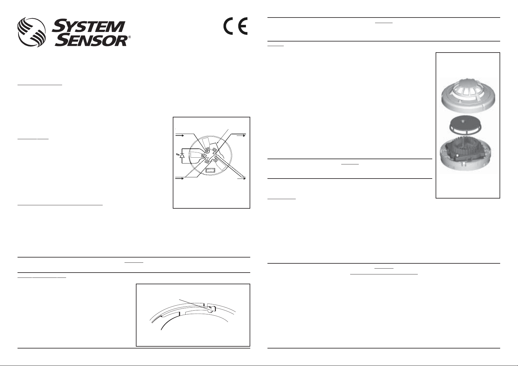
Figure 1: Base Terminal Wiring
SHORTING
SPRING
V- V-
2
+
V+ V+
NOTE: WHEN A BASE FITTED WITH A RESISTOR (R) BETWEEN
TERMINALS 4 AND 5 IS USED, THE WIRING SHOULD FOLLOW
THE DASHED LINE.
A SCHOTTKY DIODE CONNECTED BETWEEN TERMINALS 2
AND 3 DOES NOT AFFECT THE BASE WIRING.
TO REMOVE A DETECTOR ONCE THE TAMPER RESIST
FEATURE HAS BEEN ACTIVATED, INSERT A SMALL
SCREWDRIVER INTO THE SLOT IN THE SIDE OF THE BASE
AND APPLY PRESSURE TOWARDS THE BASE WHILST
ROTATING THE DETECTOR IN AN ANTI-CLOCKWISE
DIRECTION.
3
1
4
5
R
1
re-decoration or other dust producing activity. Dust covers m ust be removed before the system can be made operational.
TESTING
Detectors must be tested after installation and following periodic maintenance. However, before testing,
notify the proper authorities that the system is undergoing maintenance and the system will be
temporarily out of service. Disable the zone or system undergoing maintenance to prevent unwanted
alarms.
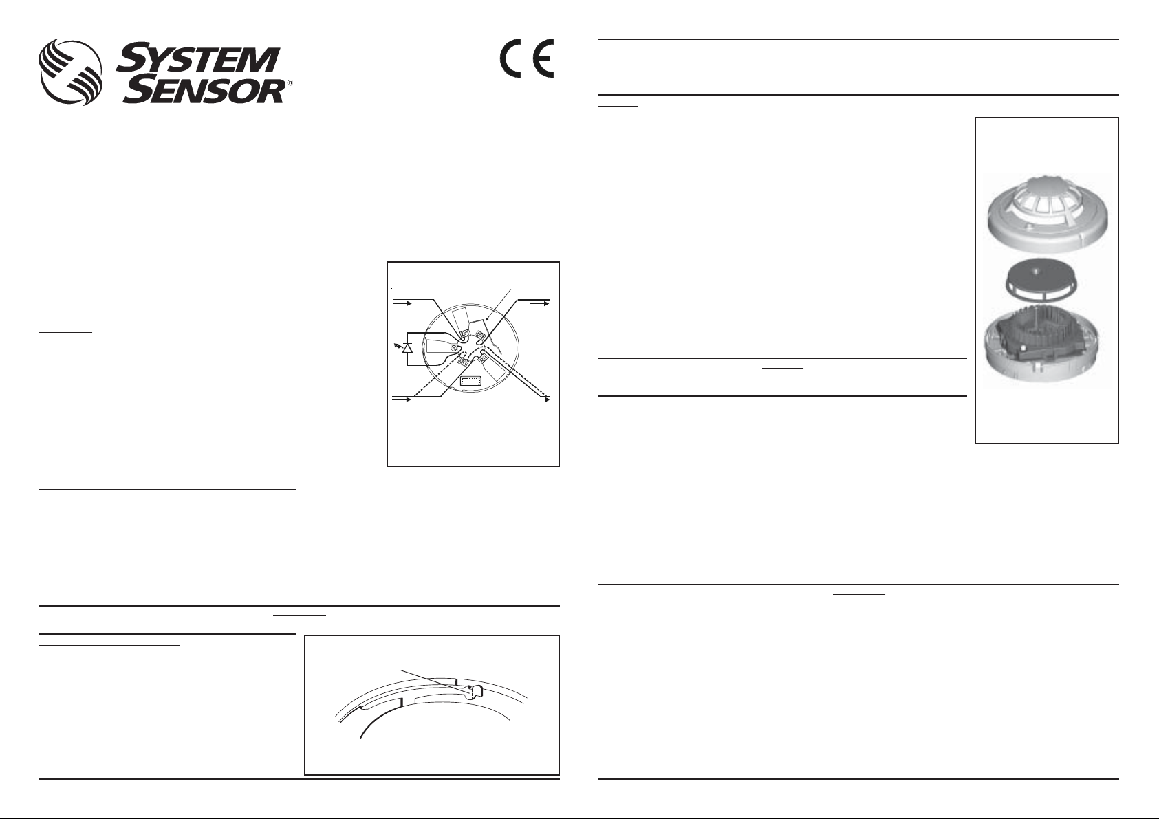
Figure 3: 2351TEM Photo
/ Thermal Fire Detector
T est the detector as follows:
Smoke method
1. Using generated smoke, or synthetic smoke aerosol from an approved manufacturer such as No
Climb Products Ltd, subject the detector to controlled amounts of smoke in accordance with local
codes of practice and manufacturer recommendations.
2. The red led on the detector should latch into alarm within 40 seconds, and the control panel should
activate into alarm.
DETECTOR COVER
Direct Heat Method
1. Use either a specialised tool such as supplied by No Climb Products Limited, or a hairdryer of
1000 to 1500 Watts.
2. Direct the heat towards the sensor thermistor from its side. Hold the heat source about 15cm
away from the detector to prevent damage during the test.
3. The red LED on the detector should latch into alarm within 40 seconds, and the control panel
should activate into alarm.
Laser test tool method (model no. S300RTU)
Note: this method does not carry out a complete functional test of the detector.
1. Align the flashing red spot produced by the laser beam with the led on the detector.
2. The red led on the detector should latch into alarm within a few seconds, and the control panel
should activate into alarm.
SCREEN
SENSING
CHAMBER
CAUTION
Do not direct the beam towards a person’s face or eyes, as eye damage may occur
Detectors that fail these tests should be cleaned as described under MAINTENANCE and re-tested. If
the detectors still fail these tests they should be returned for repair.
The S300RTU test tool is a Class II laser product.
DETECTOR
BASE
After completion of all tests notify the proper authorities that the fire system is operational.
MAINTENANCE
Before cleaning, notify the proper authorities that the system is undergoing maintenance and will be
temporarily out of service. Disable the system to prevent unwanted alarms.
1. Remove the detector to be cleaned from the system.
2. Gently release each of the cover removal tabs that secure the cover in place by inserting a small screwdriver into the recess, and gently
levering outwards, and remove the detector cover.
3. Vacuum the outside of the screen carefully without removing it.
4. Carefully remove the screen from the sensing chamber. Replacement screens are available.
5. Use a vacuum cleaner and/or clean, compressed air to remove dust and debris from the sensing chamber and the inside of the screen.
6. Re-install the screen by aligning the arrow moulded on it with the arrow on the sensing chamber, sliding the screen over the chamber and
applying gentle pressure to secure it in place.
7. Reinstall the detector cover. Align the led with the cover assembly and snap the cover into place, ensuring that all the cover removal tabs
are correctly engaged.
8. When all the detectors have been cleaned, restore power to the circuit and test the detector as described in TESTING abov e.
After maintenance has been completed, notify the proper authorities that the fire system is operational.
WARNING
LIMITATIONS OF SMOKE DETECTORS
This smoke detector is designed to activate and initiate emergency action but will do so only when used in conjunction with other equipment.
Smoke detectors will not work without power.
Smoke detectors will not sense fires which start where smoke does not reach the detectors. Smoke from fires in chimneys, in walls, on
roofs, or on the other side of closed doors may not reach the smoke detector and trigger the unit.
A detector may not detect a fire developing on another level of a building. For this reason, detectors should be located on every level of a
building.
Smoke detectors also have sensing limitations. In general, detectors can not be expected to provide warnings for fires resulting from
inadequate fire protection practices, violent explosions, escaping gas, improper storage of flammable liquids like cleaning solvents, other safety
hazards, or arson. Smoke detectors used in high air velocity conditions may fail to alarm due to dilution of smoke densities created by such
frequent and rapid air exchanges. Additionally, high air velocity environments may create increased dust contamination, demanding more frequent
maintenance.
Smoke detectors cannot last forever. Smoke detectors contain electronic parts. Even though detectors are made to last over 10 years, any of
these parts could fail at any time. Therefore, test your smoke detector system at least semi-annually. Clean and take care of your smoke
detectors regularly. Taking care of the fire detection system you have installed will significantly reduce your liability risks.
I56-1721-011
Page 2
Ai rivelatori è applicato un parapolvere che previene possibili danneggiamenti causati dal trasporto e limita l’ingresso nel rivelatore
CAUTELA
della polvere che si può creare nel momento dell’installazione. Questa protezione è ad ogni modo limitata; i rivelatori dovrebbero
0832
0832-CPD-0060
ISTRUZIONI DI INSTALLAZIONE E MANUTENZIONE PER IL RIVELATORE
D’INCENDIO COMBINATO OTTICO-TERMICO, MODELLO 2351TEM
Prima di installare i sensori, leggere attentamente il manuale System Sensor “Guide to Conventional Fire Systems”, che fornisce dettagli sulla
spaziatura, posizionamento, cablaggio ed applicazioni speciali dei rivelatori d’incendio. Copie gratuite di questo manuale sono disponibili presso
System Sensor.
DESCRIZIONE GENERALE
Il rivelatore d’incendio ottico-termico modello 2351TEM, unisce lo stato dell’arte della rivelazione ottica del fumo alla misura del calore, attuata
mediante termistore, per offrire grande flessibilità ed un alto grado di immunità ai falsi allarmi. Una varietà di basi adattatrici estende la
compatibilità con le centrali di controllo e permette molteplici applicazioni in campo. Questo sensore è progettato per l’utilizzo in ambienti aperti
ed devono essere utilizzati solamente con centrali di contollo compatibili.
Ogni rivelatore è dotato di un LED bicolore che indica l’allarme quando acceso in colore rosso è giallo lampeggiante per indicare lo stato di fault
della camera o per avvisare del raggiungimento del limite della compensazione del drift e, se il rivelatore viene impostato opportunamente, il
corretto funzionamento dell’unità mediante lampeggio a luce verde. Un ulteriore LED, detto avvisatore remoto, può essere collegato al sensore
utilizzando gli opportuni terminali presenti sulla base di montaggio. La condizione di allarme
viene mantenuta nel tempo è può essere terminata solamente con una rimozione, temporanea,
dell’alimentazione.
Tre livelli di sensibilità sono disponibili nel sensore 2351TEM: alta, media e bassa. Queste
possono essere selezionate utilizzando uno strumento dedicato disponibile presso System
Sensor. Lo stesso strumento può essere anche usato per accedere ai dati operativi del
rivelatore, vedere il manuale operativo per maggiori dettagli.
DATI TECNICI
Altezza: 57mm (montato su base B401)
Diametro: 102mm
Pes o: 105g (esclusa base)
Campo temperatura ambiente: -30°C a 70°C
T ensione di alimentazione: 8 - 30VDC
Velocità dell’aria: 20m/s (4000ft/min)
Campo umidità ambiente: 5 - 95%UR
Corrente di riposo:: 65µA
Condizione di allarme: T erminabile mediante temporanea
Questo sensore è stato testato indipendentemente ed approvato secondo EN54 parti 7: 2000 e
EN54 parti 5: 2000 Classe A1R
Note: Non installare in luoghi dove la temperatura normalente è inferiore a 0°C o superiore a
50°C, specialmente se si possono prevedere fenomeni di brina o condensazione
(condizionato all’assenza di condensa)
interruzione dell’alimentazione
MONTAGGIO DELLA BASE E COLLEGAMENTO AL CABLAGGIO
Verificare che la base acquistata sia compatibile con la centrale di controllo del sistema.
Basi della serie 400 possono essere montate su scatole di derivazione con centri di fissaggio a 50 oppure 60mm di interasse.
Vedere le figura 1 per i collegamenti elettrici.
Note:
1. I rivelatori della 300 sono polarizzati, devono essere collegati come indicato.
2. Interrompere sempre le linee sui morsetti per permettere la corretta supervisione del cablaggio.
3. Il cablaggio deve rispondere ai requisiti dei regolamenti e delle norme nazionali.
Ogni base della serie 400 è dotata di una molla di cortocircuito che può essere utilizzata per collegare i terminali 1 e 2 permettendo così di
verificare l’integrità del cablaggio prima di procedere al montaggio dei rivelatori. Questa molla recupera la posizione di riposo automaticamente
all’innesto di un sensore.
ATTENZIONE
Togliere alimentazione al sistema prima di installare i sensori.
INSTALLAZIONE DEL RIVELATORE
1. Posizionare il rivelatore nella base e ruotare in senso orario
esercitando una moderata pressione fino a quando il rivelatore
raggiunge la sua posizione.
2. Continuare la rotazione fino ad avvertire il blocco.
3. Quando tutti i rivelatori sono stati inseriti, alimentare il sistema.
4. Verificare i rivelatori come descritto nella sezione VERIFICA.
5. Re-inizializzare i rivelatori utilizzando la relativa funzione della
centrale di controllo.
Figura 2: anti-manomissione
PER ATTIVARE IL DISPOSITIVO DI ANTI-MANOMISSIONE, SPEZZARE LA LINGUETTA SULLA
LEVA IN PLASTICA RUOTANDOLA VERSO L’INTERNO DELLA BASE AL LIVELLO DELLA
LINEA TRATTEGGIATA
Anti-manomissione
Le basi dei rivelatori includono una caratteristica che, quando attivata,
previene la rimozione del rivelatore. Essa rimane ovviamente possibile
ma soltanto attraverso un utensile. Vedere figura 2 per i dettagli.
PER RIMUOVERE UN RIVELATORE QUANDO È ATTIVATO IL DISPOSITIVO DI ANTIMANOMISSIONE, INSERIRE UN PICCOLO CACCIAVITE A TAGLIO NELLA SEDE RICAVATA SUL
BORDO DELLA BASE, ESERCITARE UNA PRESSIONE VERSO IL FONDO DELLA BASE STESSA E
MANTENERLA MENTRE SI RUOTA IL RIVELATORE IN SENSO ANTIORARIO.
D300-04-01 Pittway Tecnologica S.p.A, Via Caboto 19/3, 34147 Trieste, Italy © System Sensor 2004
Figura1: cablaggio ai terminali della base
MOLLA DI CORTOCIRCUITO
V- V-
2
+
V+ V+
NOTA: QUANDO SI UTILIZZA UNA BASE CON UN RESISTORE TRA
I TERMINALI 4 E 5, IL CABLAGGIO DOVREBBE SEGUIRE LE
INDICAZIONI TRATTEGGIATE.
UN DIODO SCHOTTKY TRA I TERMINALI 2 E 3 NON ALTERA IL
CABLAGGIO DELLA BASE.
3
1
4
5
R
essere rimossi prima di iniziare interventi di ristrutturazione, costruzione od altre attività similari che possano produrre notevoli
quantità di polvere. Il parapolvere deve essere rimosso prima di rendere operativo il sistema di rivelazione d’incendio.
VERIFICA
I rivelatori devono essere testati successivamente all’installazione od alla manutenzione. Tuttavia
prima di iniziare queste verifiche, notificare alle autorità competenti che il sistema sarà oggetto di
manutenzione e quindi temporaneamente fuori servizio. Per prevenire allarmi indesiderati, disabilitare
le segnalazioni di incendio alle zone che saranno verificate oppure al sistema intero, in accordo a
quanto specificato nel manuale d’uso della centrale di controllo,
Verificare il rivelatore come segue:
Risposta al fumo
1. Indirizzare del fumo verso il rivelatore oppure, preferibilmente, utilizzare un “detector tester”
(prodotti No Climb Products Ltd od equivalenti) seguendo attentamente le istruzioni fornite dal
costruttore.
2. Il LED rosso sul rivelatore deve accendersi entro 40 secondi e la centrale di controllo deve
indicare la condizione di allarme.
Figura 3: Rivelatore Combinato
Ottico Termico 2351TEM
CALOTTA DEL RIVELATORE
Risposta al calore, riscaldamento diretto
1. Usare un apparecchiatura dedicata (No Climb Products Ltd od equivalenti) oppure un
asciugacapelli da 1000-1500W.
2. Indirizzare il getto d’aria calda lateralmente al rivelatore, in modo che possa attraversare lo
stesso attraverso le feritoie predisposte sull’involucro esterno.
3. Il LED rosso sul rivelatore deve accendersi entro 40 secondi e la centrale di controllo deve
indicare la condizione di allarme.
Telecomando laser (Accessorio codice S300RTU)
Nota: Questo test non verifica completamente la funzionalità del rivelatore.
1. Allineare il fascio laser (punto lampeggiante rosso) prodotto dall’accessorio al LED del rivelatore.
2. Il LED rosso sul rivelatore deve accendersi entro pochi secondi e la centrale di controllo deve
indicare la condizione di allarme.
CAUTELA
Lo strumento di test S300RTU contiene un laser di Classe II. Non puntare il fascio verso il
I rivelatori che falliscono questi test devono essere puliti come descritti nella sezione
MANUTENZIONE e sottoposti nuovamente a verifica.
viso o gli occhi delle persone.
BASE DEL RIVELATORE
MANUTENZIONE
Prima di procedere alla pulizia, notificare alle autorità competenti che il sistema sarà oggetto di
manutenzione e quindi temporaneamente fuori servizio. Per prevenire allarmi indesiderati, disabilitare
le segnalazioni di incendio alle zone che saranno verificate oppure al sistema intero, in accordo a
quanto specificato nel manuale d’uso della centrale di controllo.
1. Rimuovere dalla sua base il rivelatore da pulire.
2. Rilasciare con delicatezza i ganci che trattengono la calotta inserendo un piccolo cacciavite a taglio nelle relative sedi e spingendo i ganci
verso l’interno.
3. Utilizzando un aspirapolvere, rimuovere con cura fibre e polvere che possono essersi depositate sul coperchio della camera ottica.
4. T ogliere il coperchio della camera ottica. Questa parte è disponibile come ricambio.
5. Utilizzando un aspirapolvere oppure dell’aria compressa, rimuovere fibre e polvere dalla camera ottica e, in caso venga riutilizzato, dalla
parte interna del coperchio.
6. Posizionare il coperchio della camera ottica nella sua sede (le frecce in basso rilievo indicano il corretto orientamento) esercitando una
moderata pressione per assicurarne il fissaggio
7. Rimontare la calotta del rivelatore (il foro per il LED sulla calotta indica il corretto orientamento) assicurandosi che tutti i ganci trattengano
correttamente la parte interna del rivelatore.
8. Quando tutti i rivelatori sono stati puliti, alimentare il sistema e testare i rivelatori come descritto nella sezione VERIFICA.
ATTENZIONE
LIMITAZIONI DEI RIVELATORI DI FUMO
Questo rivelatore di fumo è progettato per attivare azioni di emergenza ma lo può fare solamente se utilizzato in abbinamento ad altre
apparecchiature (centrale di controllo, avvisatori acustici ecc.). I rivelatori di fumo non funzionano in mancanza di alimentazione.
I rilevatori di fumo non percepiscono incendi che si sviluppano in aree in cui il fumo non raggiunge i rivelatori. Il fumo proveniente da camini,
pareti o tetti, o sul lato opposto di porte chiuse, non raggiunge il rilevatore di fumo e quindi non aziona l’unità.
Un rilevatore potrebbe non essere in grado di rilevare un incendio sviluppatosi su un altro livello dell’edificio. Per questa ragione, è necessario
posizionare i rilevatori su ciascun livello dell’edificio stesso.
I rivelatori di fumo hanno inoltre alcune limitazioni relative al rilevamento. In generale, non ci si può aspettare che i rivelatori di fumo forniscano
avvisi per incendi generati da pratiche antincendio improprie, violente esplosioni, fughe di gas, impropria conservazione di liquidi infiammabili
come solventi per pulizia, incendi dolosi e mancato rispetto delle condizioni di sicurezza. È possibile che rilevatori utilizzati in aree fortemente
ventilate non generino allarme, a causa della diluizione della densità del fumo creata da tali frequenti e rapidi passaggi d’aria.
Inoltre, ambienti fortemente ventilati possono incidere sull’aumento della presenza di agenti contaminanti, richiedendo una maggiore frequenza
delle operazioni di manutenzione.
I rilevatori di fumo non durano per sempre. I rilevatori di fumo contengono parti elettroniche. Anche se i rilevatori sono stati progettatati per una
durata di 10 anni, è possibile che alcune parti si guastino in qualsiasi momento. Pertanto, si consiglia vivamente di verificare il proprio sistema di
rilevamento di fumo, almeno ogni sei mesi. È importante eseguire regolarmente sia la pulizia che le operazioni di manutenzione richieste.
Un’adeguata cura del sistema di rivelazione incendio installato, riduce significativamente i rischi di malfunzionamento dello stesso.
2
COPERCHIO
CAMERA OTTICA
I56-1721-011
Page 3

Los detectores se suministran con tapa para protegerlos del polvo durante el transporte y etapa inicial de la instalación. No se
PRECAUCIÓN
pretende que estas tapas ofrezcan protección total contra todo tipo de contaminación; por ello, antes de iniciarse cualquier trabajo
0832
0832-CPD-0060
INSTRUCCIONES DE INSTALACIÓN Y MANTENIMIENTO PARA EL
DETECTOR DE FUEGO FOTOTÉRMICO DE BAJO PERFIL MODELO 2351TEM
Antes de instalar los detectores, lea detenidamente la Guía de Sistemas Convencionales de Detección de Incendios de System Sensor, que le
proporcionará información detallada acerca de la distancia, ubicación, tipo de zonas y aplicaciones especiales del detector. Pueden obtenerse
copias de dicho manual sin cargo adicional por parte de System Sensor.
DESCRIPCIÓN GENERAL
Los detectores de fuego fototérmicos modelo 2351TEM combinan cámaras de detección óptica de última generación con termistores para
ofrecer mayor flexibilidad y más inmunidad a las falsas alarmas. La capacidad de conectar estos detectores a diversas opciones de base amplía
la compatibilidad con paneles y la flexibilidad de aplicación. Estos detectores han sido diseñados para proporcionar protección en zonas diáfanas
y sólo se pueden utilizar con paneles de control compatibles.
Un led bicolor en el detector se ilumina en rojo para indicar alarma, parpadea en amarillo para indicar fallo de cámara o que se ha alcanzado el
nivel máximo de compensación por suciedad, y también se puede ajustar para que parpadee en verde para indicar que el detector está
funcionando correctamente. Se puede disponer de un LED indicador remoto como accesorio opcional conectado a los terminales de base
estándar. Estos detectores también poseen la función de enclavamiento de alarma. Ésta sólo
puede desactivarse mediante una interrupción momentánea del suministro eléctrico.
System Sensor dispone de una herramienta específica para acceder a los datos de
funcionamiento del detector: Consulte el manual de funcionamiento de esta herramienta si
desea más detalles.
ESPECIFICACIONES
Alto: 57 mm (montado en una base B401)
Diámetro: 102 mm
Peso: 105 g (sin base)
T emperatu ra de Funcionamiento: -30°C a 70°C
T ensión de Alimentación: 8 - 30Vcc
Velocidad del Aire: 20m/s (4000pies/min)
Humedad: 5 - 95%HR (sin condensación)
Corriente en reposo: 65µA
Enclavamiento de la Alarma: Rearmado mediante supresión
Este detector ha sido probado y certificado independientemente según CEA4021, incluyendo
EN54-7: 2000 y EN54-5: 2000 Clase A1R.
Nota: No instalar en zonas en las que el margen de temperatura ambiente normal se
extienda más allá de 0°C a 50°C durante largos periodos de tiempo, en particular, si
se esperan fenómenos de heladas o condensación.
momentánea de la tensión de
alimentación.
MONTAJE DE LA BASE E INSTRUCCIONES DE CABLEADO
Compruebe que la base suministrada con el detector es compatible con el panel de control del sistema.
Las bases de la serie 400 se pueden montar en las cajas de conexiones eléctricas estándar por medio de fijaciones centrales de 50-60 mm.
Vea las conexiones de los terminales en la figura 1. Si se v an a utilizar bases con relé, consulte las instrucciones de la base en cuestión.
Notas:
1. Los detectores de la serie 300 tienen polaridad y se deben cablear según se indica.
2. No haga ramales con los cables comunes: Interrumpa el recorrido del hilo para asegurar la supervisión de las conexiones.
3. T odo el conexionado deberá cumplir la normativa y reglamentos locales y nacionales aplicables
Las bases de la serie 400 disponen de una pestaña metálica de continuidad que se puede utilizar para conectar los terminales 2 y 3, permitiendo
así la comprobación del cableado del lazo antes de la instalación de las cabezas detectoras. Esta pestaña se desconecta automáticamente al
acoplar el detector en la base.
AVISO
Desconecte la alimentación de la línea de los detectores antes de instalar éstos.
INSTALACIÓN DEL DETECTOR
1. Sitúe el detector en su base y gírelo en sentido horario ejerciendo
una ligera presión, hasta que éste quede en su lugar.
2. Continúe girando el detector en el mismo sentido para
inmovilizarlo en su sitio.
3. Una vez instalados los detectores conecte la alimentación de los
circuitos de monitorización de éstos.
4. Compruebe el detector según se describe en el apartado
PRUEBAS.
5. Rearme el detector en el panel de control del sistema.
Opción de seguridad antimanipulaciones (bloqueo de extracción
del detector)
La base del detector incluye una opción que, si se utiliza, impide que se
extraiga el detector si no es mediante el uso de una herramienta. Vea
los detalles en la figura 2.
Figura 2: Opción de seguridad antimanipulaciones
PARA ACTIVAR LA OPCIÓN ANTIMANIPULACIONES, ROMPA LA LENGÜETA DE
PLÁSTICO POR LA LÍNEA DE PUNTOS GIRÁNDOLA HACIA EN CENTRO DE LA BASE.
PARA RETIRAR UN DETECTOR UNA VEZ ACTIVADA LA OPCIÓN ANTIMANIPULACIONES,
INSERTE UN DESTORNILLADOR PEQUEÑO EN LA RANURA DE LA CARCASA DEL DETECTOR Y
PRESIONE LIGERAMENTE MIENTRAS GIRA EL DETECTOR EN SENTIDO ANTIHORARIO.
D300-04-01 Pittway Tecnologica S.p.A, Via Caboto 19/3, 34147 Trieste, Italy © System Sensor 2004
Figura 1: Cableado de los T erminales de
la Base
V- V-
+
V+ V+
NOTA: CUANDO SE UTILIZA UNA BASE CON RESISTENCIA (R)
ENTRE LOS TERMINALES 4 Y 5, EL CABLEADO A SEGUIR ES EL
DE LA LÍNEA DE PUNTOS.
LA CONEXIÓN DE UN DIODO SCHOTTKY ENTRE LOS
TERMINALES 2 Y 3 NO AFECTA AL CABLEADO DE LA BASE.
PESTAÑA METÁLICA DE CONTINUIDAD
2
3
1
4
5
R
de construcción, decoración u otra actividad que genere polvo, los detectores deben ser retirados. Extraiga esta protección antes de
la puesta en marcha del sistema.
PRUEBAS
Los detectores han de comprobarse una vez instalados y durante los mantenimientos periódicos
posteriores. En cualquier caso, antes de realizar las pruebas, avise a las autoridades competentes que
se está realizando el mantenimiento del sistema y que éste permanecerá temporalmente fuera de
servicio. Anule el sistema para evitar alarmas no deseadas.
Figura 3: Detector Foto
Térmico 2351TEM
Compruebe el detector como sigue:
Método de Humo
1. Someta el detector a cantidades controladas de humo utilizando humo generado o humo sintético
en aerosol suministrado por un fabricante homologado, como No Climb Products Ltd, de acuerdo
con las reglas técnicas locales y las recomendaciones del fabricante.
2. El LED rojo del detector ha de encenderse y quedar enclavado en estado de alarma en los 40
segundos siguientes, activándose la alarma en el panel de control.
TAPA DEL DETECTOR
Método de Calor Directo
1. Utilice una herramienta especializada, como la que suministra No Climb Products Ltd, o bien un
secador de pelo de 1000-1500 V atios.
2. Dirija el calor lateralmente hacia el sensor. Mantenga la fuente de calor a una distancia de 15 cm
para evitar daños durante la comprobación.
3. El LED rojo del detector ha de encenderse y quedar enclavado en estado de alarma en los 40
segundos siguientes, activándose la alarma en el panel de control.
Método de Prueba con Láser (Modelo Núm. S300RTU)
Nota: Este método no lleva a cabo una comprobación funcional completa del detector.
1. Alinee el punto rojo producido por el rayo láser con el LED del detector.
2. El LED rojo del detector ha de encenderse y quedar enclavado en estado de alarma a los pocos
segundos, activándose la alarma en el panel de control.
PRECAUCIÓN
El Láser S300RTU es un producto láser de Clase II. No dirija el haz a la cara u ojos de las
Los detectores que fallen en dichas comprobaciones han de limpiarse según lo descrito en el apartado
MANTENIMIENTO y comprobarse de nuevo. Si éstos siguiesen fallando en dichas comprobaciones,
habrán de ser devueltos a fábrica para su reparación.
Una vez realizadas las pruebas, notifique a las autoridades competentes que el sistema está
funcionando.
personas, podría causarles lesiones oculares
BASE DEL DETECTOR
MANTENIMIENTO
Antes de limpiar los equipos avise al personal responsable que se está realizando el mantenimiento
del sistema y que éste permanecerá momentáneamente fuera de servicio. Anule el sistema para evitar alarmas no deseadas.
1. Retire del sistema el detector que vaya a limpiar.
2. Libere con cuidado cada una de las lengüetas que sujetan la tapa del detector introduciendo un destornillador en el hueco para hacer palanca
y retire dicha tapa.
3. Limpie aspirando con cuidado la parte exterior de la pantalla sin desmontarla.
4. Desmonte con cuidado la pantalla de la cámara de detección. Existen tornillos de repuesto disponibles.
5. Utilice un aspirador o aire comprimido limpio para eliminar el polvo y la suciedad de la cámara de detección y del interior de la pantalla.
6. Reinstale la pantalla alineando la flecha grabada en ella con la flecha de la cámara de detección, deslizando la pantalla sobre la cámara de
detección y presionando ligeramente para anclarla en su lugar.
7. Reinstale la tapa del detector. Alinee el LED con la tapa y encaje ésta en su sitio, asegurándose de que las lengüetas de fijación de la tapa
están ancladas correctamente.
8. Cuando termine de limpiar todos los detectores, conecte la alimentación al circuito y compruébelos según se describe en el apartado
PRUEBAS.
Una vez finalizadas las tareas de mantenimiento, notifique al personal responsable que el sistema está funcionando.
AVISO
LIMITACIONES DE LOS DETECTORES DE HUMO
Este detector de humo ha sido diseñado para activar e iniciar una acción de emergencia, pero sólo lo hará si se utiliza en conjunción con otro
equipo. Los detectores de humo no funcionan sin alimentación eléctrica.
Los detectores de humo no detectarán fuegos que comiencen en lugares en los que el humo no alcance los detectores. El humo de fuegos en
chimeneas, paredes, tejados o al otro lado de puertas cerradas podría no llegar al detector de humo y no activarlo.
Un detector podría no detectar un fuego que se desarrolla en otra planta del edificio. Por ello, los detectores se han de situar en cada planta de un
edificio.
Los detectores de humo también poseen limitaciones de detección. En general, no es de esperar que los detectores proporcionen alarmas de
fuegos causados por prácticas inadecuadas de protección contra incendio, explosiones violentas, escapes de gas, almacenamiento inadecuado
de líquidos inflamables, tales como disolventes líquidos, otros riesgos de seguridad o incendios provocados. Los detectores de humo utilizados
en ambientes donde la velocidad del viento es muy elevada pueden no generar alarmas debido a la dilución de la densidad del humo a causa de
tales intercambios frecuentes y rápidos de aire. Además, los ambientes con alta velocidad del aire pueden incrementar la contaminación por
polvo, precisándose mantenimientos más frecuentes.
Los detectores de humo tienen una duración limitada. Los detectores de humo contienen componentes electrónicos. A pesar de que los
detectores se fabrican para que duren más de diez años, cualquiera de sus componentes podría fallar en cualquier momento. Por ello, pruebe su
sistema de detección de incendios al menos cada seis meses. Limpie y realice el mantenimiento de los detectores de humo regularmente. El
cuidado del sistema de detección de incendios que ha instalado reducirá notablemente riesgos en cuanto a su responsabilidad con el producto.
3
PANTALLA
CÁMARA DE
DETECCIÓN
I56-1721-011
Page 4

Der Melder ist werkseitig mit einem Staubschutz vor V er schm utzung während des Transportes oder der Erstinstallation geschützt.
Ein vollständiger Schutz gegen eine V erunreinigung ist dadurch nicht ge währleistet. Deshalb sollten die Melder v or Beginn von
0832
0832-CPD-0060
Konstruktions-, umfangreichen Dekorationsarbeiten oder sonstigen Aktivitäten mit Staubentwicklung entfernt werden. Zur
ordnungsgemäßen Funktion ist der Staubschutz vor der Inbetriebnahme des Melders abzunehmen.
PRÜFUNG
ACHTUNG
INSTALLATIONS- UND WARTUNGSANLEITUNG ZUM OPTISCH-
THERMISCHEN BRANDMELDER TYP 2351TEM
Bevor Sie mit der Installation der Brandmelder beginnen, lesen Sie bitte die sorgfältig die System Sensor Anleitung zum Umgang mit Rauch- und
Wärmemeldern, in der wichtige Informationen zum Melderabstand, der Anordnung, der Überwachungsfläche sowie der Verdrahtung und
Anwendung enthalten sind. Diese Anleitung kann kopiert werden, ohne die Kosten hierfür System Sensor in Rechnung zu stellen.
ALLGEMEINE BESCHREIBUNG
Der optisch-thermische Brandmelder Typ 2351TEM besteht aus einer hochmodernen Messkammer mit einem optischen Rauchsensor und
einem Wärmesensor und bietet eine größere Flexibilität und höhere Sicherheit gegen Falschalarme. Die Möglichkeit diesen Melder mit
unterschiedlichen Meldersockeln einzusetzen erweitert den Einsatzbereich und die Flexibilität des Brandmeldesystems. Dieser Melder wurde
zur Brandfrüherkennung in Räumen entwickelt und darf nur in Verbindung mit k ompatiblen Brandmelderzentralen betrieben werden.
Die zweifarbige LED des Melders leuchtet rot auf wenn der Melder sich im Alarmzustand befindet, blinkt gelb wenn eine Störung der
Messkammer aufgetreten bzw. das Ende der Messwertnachführung erreicht ist und blinkt grün im Normalbetrieb des Melders. Zusätzlich kann
eine optionale Parallelanzeige an den Meldersockel angeschlossen werden. Alle Brandmelder sind mit einer Alarmspeicherung ausgerüstet, die
durch kurzzeitige Unterbrechung der Betriebsspannung wieder gelöscht werden kann.
Mit einem speziellen System Sensor Werkzeug kann auf die Betriebsdaten des Brandmelders
zugegriffen werden, näheres hierzu ist in der Bedienungsanleitung beschrieben.
SPEZIFIKATION
Höhe 57mm (inkl. Meldersockel Typ B401)
Durchmesser 102mm
Gewicht 105g (ohne Meldersockel)
Betriebstemperaturbereich -30 °C bis 70 °C
Versorgungsspannung 0 - 30 VDC
Luftgeschwindigkeit 20m/s (4000ft/min)
Luftfeuchtigkeit 5-95% rel. (ohne Betauung)
Ruhestrom 65µA, typisch
Alarmspeicherung Rücksetzbar durch kurzzeitige
Der optisch-thermische Brandmelder T yp 2351TEM wurde unabhängig geprüft und entspricht
den V orgaben und Richtlinien der CEA4021 inkl. der EN54-7:2000 und der EN54-5:2000 Klasse
A1R.
Hinweis: Installieren Sie den Melder nicht an Orten an denen der zulässige
Betriebstemperaturbereich von 0°C bis 50 °C unter Umständen längere Zeit
überschritten werden könnte oder wo mit Vereisung und Kondensation gerechnet
werden kann.
Unterbrechung der Betriebsspannung
MONTAGE UND VERDRAHTUNG DES MELDERSOCKELS
Vergewissern Sie sich das der eingesetzte Meldersoc kel und die Brandmelderz entrale zueinander k ompatibel sind.
Die Meldersockel der Serie 400 können auf Standard Verteilerdosen mit den 50-60mm Befestigungslöcher montiert werden.
Die Abbildung 1 zeigt die Klemmenbelegung der Standardsockel. Wenn Relaissockel eingesetzt werden folgen Sie den Hinweisen der
entsprechenden Installationsanleitung sowie dem V erpackungsaufdruck.
Hinweise:
1. Polarität beachten, Melder der Serie 300 müssen gemäß der o.a. Abbildung verdrahtet werden.
2. Keine Kabelschlaufen unter die Klemmen legen. Zur besseren Übersicht sollte die Kabelführung unterbrochen sein.
3. Die Verdrahtung muss gemäß den gültigen regionalen Richtlinien und gesetzlichen Bestimm ungen ausgeführt werden.
Um die V erdrahtung vor dem Einsetz en der Brandmelder überprüfen zu können, ist eine Metallfeder zum Überbrüc ken der beiden Klemmen Nr . 2
und Nr.3 eingebaut. Die Überbrückung wird mit dem Einsetzen des Brandmelders automatisch wieder beseitigt.
WARNUNG
Melder nur im spannungsfreien Zustand einsetzen
INSTALLATION DES MELDERS
1. Setzen Sie den Melder in den Sockel und drehen ihn mit leichtem
Druck im Uhrzeigersinn bis er in den Sockel passt.
2. Drehen Sie jetzt vorsichtig weiter bis der Melder im Sockel
einrastet.
3. Nachdem alle Melder installiert sind schalten Sie die
Spannungsversorgung ein.
4. Prüfen Sie den Melder wie im Abschnitt Prüfung beschrieben.
5. Setzen Sie den Melder an der Zentrale zurück (Reset)
Abbildung 2: Sabotageschutz / Entnahmesicherung
ZUM AKTIVIEREN MUSS DIE SOLLBRUCHSTELLE AN DER GEPUNKTETEN LINIE DURCH
DREHEN IN RICHTUNG GEHÄUSEMITTE HERAUSGEBROCHEN WERDEN.
Sabotageschutz / Entnahmesicherung
Der Meldersockel verfügt über eine Entnahmesicherung die das
Entfernen des Brandmelders aus dem Sockel nur mit Hilfe eines
Werkzeuges zulässt.
ZUM ENTNEHMEN DES MELDERS BEI AKTIVIERTER ENTNAHMESICHERUNG STECHEN SIE MIT
EINEM SCHMALEN SCHLITZSCHRAUBENDREHER IN DIE SEITLICHE ÖFFNUNG DES
MELDERSOCKELS. DRÜCKEN SIE DIE PLASTIKZUNGE VON DEM MELDER WEG UND DREHEN SIE
DEN MELDER GEGEN DEN UHRZEIGERSINN AUS DEM SOCKEL.
D300-04-01 Pittway Tecnologica S.p.A, Via Caboto 19/3, 34147 Trieste, Italy © System Sensor 2004
Abbildung 1: Verdrahtung des
Meldersockels
V- V-
+
V+ V+
HINWEIS: MELDERSOCKEL MIT EINEM WIDERSTAND
ZWISCHEN DEN KLEMMEN 4 UND 5 SIND GEMÄß DER
GESTRICHELTEN LINIE ZU VERDRAHTEN.
EINE SCHOTTKY DIODE ZWISCHEN DEN KLEMMEN 2 UND 3 HAT
KEINEN EINFLUß AUF DIE VERDRAHTUNG
2
1
5
METALLFEDER
3
4
R
Für die installierten Melder ist eine Prüfung und in regelmäßigen Abständen die folgende Wartung
durchzuführen. Vor Beginn sind die entsprechenden Interventionskräfte und Beteiligten über die
Außerbetriebnahme der Anlage zu informieren. Schalten Sie die Meldergruppen und
Alarmweiterleitung ab um unerwünschte Alarmmeldungen während der Wartung zu unterdrücken.
Abbildung 3: 2351TEM Optisch/
Thermischer Brandmelder
Prüfen Sie den Melder wie folgt:
Rauchsensor prüfen
1. Lösen Sie den Melder mit Rauch oder geeignetem T estgas von empfohlenen Herstellern, z.B. No
Climb Products Ltd., mit einer dosierten Rauchmenge, gemäß den regionalen Vorschriften und
Empfehlungen des Herstellers aus.
2. Die Auslösung des Melders sollte innerhalb von 40s durch die leuchtende rote Melder-LED und
der Brandmelderzentrale angezeigt werden.
MELDERGEHÄUSE
Wärmesensor prüfen
1. Lösen Sie den Melder mit einem Testgerät für Wärmemelder, wie z.B. von der Firma No Climb
Products Ltd. angeboten, oder durch einen Haarfön mit 1000-1500 Watt Leistung aus.
2. Richten Sie die Warmluft von der Melderseite auf den Wärmesensor. Halten Sie dabei einen
Abstand von mindestens 15cm ein um den Melder nicht zu beschädigen.
3. Die Auslösung des Melders sollte innerhalb von 40s durch die leuchtende rote Melder-LED und
der Brandmelderzentrale angezeigt werden.
Prüfung mit dem Laser-Testgerät (Typ S300RTU)
Hinweis: Diese Methode ist keine vollständige Überprüfung der Melderfunktionalität
1. Richten Sie den rot blitzenden Laserpunkt des T estgerätes auf die Melder-LED aus
2. Die Auslösung des Melders sollte innerhalb weniger Sekunden durch die leuchtende rote MelderLED und der Brandmelderzentrale angezeigt werden.
ACHTUNG
Das Laser-Testgerät ist ein Produkt der Laser Klasse II. Verletzungsgefahr - Richten Sie den
Melder die nicht ausgelöst werden können, müssen gemäß der Wartungsanweisung gereinigt und
erneut getestet werden.
Informieren Sie nach dem Abschluss der Prüfungen die Interventionskräfte und Beteiligten wieder über
die Inbetriebnahme der meldebereiten Brandmeldeanlage.
Laserstrahl niemals direkt auf Gesichter oder Augen
MELDERSOCKEL
WARTUNG
Vor Beginn der sind die entsprechenden Interventionskräfte und Beteiligten über die War tung und
Außerbetriebnahme der Anlage zu informieren. Schalten Sie die Meldergruppen und Alarmweiterleitung ab um unerwünschte Alarmmeldungen
während der Wartung zu unterdrücken.
1. Entnehmen Sie die zu reinigenden Melder
2. Lösen Sie mit einem schmalen Schlitzschraubendreher das Meldergehäuse an den seitlichen Öffnungen und drücken Sie die Plastikzunge
vorsichtig nach Außen. Nehmen Sie des Meldergehäuse ab.
3. Reinigen Sie das Fliegengitter vorsichtig von der Außenseite ohne es zu entfernen.
4. Nehmen Sie jetzt das Fliegengitter von der Sensorkammer ab. Ersatzgitter sind erhältlich.
5. Entfernen Sie den Staub mit einem geeigneten Staubsauger oder mit Pressluft aus der Sensorkammer und von der Innenseite des
Fliegengitters.
6. Setzen Sie das Gitter wieder ein indem Sie es an den Pfeilmarkierungen mit der Sensorkammer ausrichten und mit leichtem Druck
aufstecken.
7. Setzen Sie das Gehäuse wieder auf indem Sie die Melder-LED mit der entsprechenden Gehäuseöffnung ausrichten. V ergewissern Sie sich
das alle Plastikzungen der Gehäusebefestigung ordnungsgemäß einrasten.
8. Nach der Melderreinigung schalten Sie die Betriebsspannung ein und prüfen alle Melder wie unter PRÜFUNG beschrieben.
Informieren Sie nach dem Abschluss der Prüfungen die Interventionskräfte und Beteiligten wieder über die Inbetriebnahme der meldebereiten
Brandmeldeanlage.
WARNUNG
EINSCHRÄNKUNG VON RAUCHMELDERN
Dieser Rauchmelder wurde zur Brandfrüherkennung und Alarmierung entwickelt und funktioniert nur in Verbindung mit Zusatzgeräten. Zum
Betrieb benötigen Rauchmelder eine Spannungsversorgung.
Rauchmelder erkennen keinen Brand wenn die Rauchentwicklung nicht bis zum Melder vordringt. Bei Brandrauch aus Kaminbränden,
Wänden, Dächern oder hinter geschlossenen Türen ist die Auslösung des Rauchmelders nicht gewährleistet.
Ein Brandmelder kann die Brandentstehung auf einer anderen Gebäudeetage nicht erkennen. Deswegen sollten alle Etagen eines
Gebäudes mit eigenen Brandmeldern ausgerüstet werden.
Rauchmelder haben technisch begrenzte Grenzen bei der Branderkennung. Grundsätzlich ist nicht zu erwarten, dass der Melder durch
ungeeignete Feuerschutzübungen, heftigen Explosionen, ausströmendes Gas, unsachgemäßer Lagerung von brennbaren Flüssigkeiten wie z.B.
Lösungsmitteln sowie sonstigen Sicherheitsrisiken oder Brandstiftung ausgelöst wird. Bei Rauchmeldern die an Orten mit hoher Luftbewegung
eingesetzt werden kann im Ereignisfall die Funktion des Melders durch die Abschwächung der Rauchdichte beeinträchtigt werden. Zusätzlich
wird in dieser Umgebungsbedingung die V erschmutzung des Melders und somit auch der W artungsaufwand erhöht.
Rauchmelder haben eine begrenzte Lebensdauer und beinhalten elektronische Bauteile. Obwohl die Melder für eine Lebensdauer von
mehr als 10 Jahren ausgelegt sind, ist ein Bauteildefekt zu keinem Zeitpunkt auszuschließen. Deshalb prüfen Sie die Rauchmelder halbjährlich.
Reinigen und inspizieren Sie die Melder regelmäßig. Durch die ordnungsgemäße Instandhaltung des von Ihnen installierten Brandmeldesystems
kann das Haftungsrisiko erheblich reduziert werden.
4
FLIEGENGITTER
SENSORKAMMER
I56-1721-011
 Loading...