

Page 1
D200-08-00 1 I56-0001-01R
2251TM Intelligent
Photoelectronic Smoke Sensor
INSTALLATION AND MAINTENANCE INSTRUCTIONS
A Division of Pittway
3825 Ohio Avenue, St. Charles, Illinois 60174
1-800-SENSOR2, FAX: 630-377-6495
Before Installing
This sensor must be installed in compliance with the control panel system installation manual. The installation must
meet the requirements of the Authority Having Jurisdiction
(AHJ). Sensors offer maximum performance when installed
in compliance with the National Fire Protection Association
(NFPA); see NFPA 72.
General Description
Model 2251TM is a plug-in type smoke sensor that combines a photoelectronic sensing chamber and 135°F
(57.2°C) fixed temperature heat detection. The sensor uses
analog-addressable communications to transmit smoke density and other information to the control panel. Rotarydecade switches are provided for setting the sensor’s
address. Two LEDs on the sensor are controlled by the
panel to indicate sensor status. An output is provided for
connection to an optional remote LED annunciator (P/N
RA400Z).
This detector requires compatible addressable communications to function properly. Connect this sensor to
listed-compatible control panels only.
Spacing
System Sensor recommends spacing sensors in compliance
with NFPA 72. In low air flow applications with smooth
ceilings, space sensors 30 feet apart. For specific information regarding sensor spacing, placement, and special
applications, refer to NFPA 72 or the System Sensor Guide
For Proper Use of System Smoke Detectors
, available from
System Sensor (P/N I56-407-XX).
Specifications
Operating Voltage Range: 15 to 32 VDC
Standby Current: 300µA @ 24 VDC (one communication every 5 sec. with LED blink enabled)
Max. Alarm Current (LED on:) 6.5 mA @ 24 VDC
Operating Humidity Range: 10% to 93% Relative Humidity, noncondensing
Operating Temperature Range: 0° to 38°C (32° to 100°F)
Heat Sensor: 135°F Fixed Temperature Electronic Thermistor
Height: 1.7 inches (43 mm) installed in B210LP Base
Diameter: 6.1 inches (155 mm) installed in B210LP Base
4.1 inches (104 mm) installed in B501 Base
Weight: 5.0 oz. (142 g)
Additional Bases Available: All 200/500 Series bases are compatible.
Wiring Instructions
All wiring must be installed in compliance with the
National Electrical Code, applicable local codes, and any
special requirements of the Authority Having Jurisdiction.
Proper wire gauges should be used. The installation wires
should be color-coded to limit wiring mistakes and ease
system troubleshooting. Improper connections will prevent
a system from responding properly in the event of a fire.
Remove power from the communication line before
installing sensors.
All wiring must conform to applicable local codes, ordinances, and regulations.
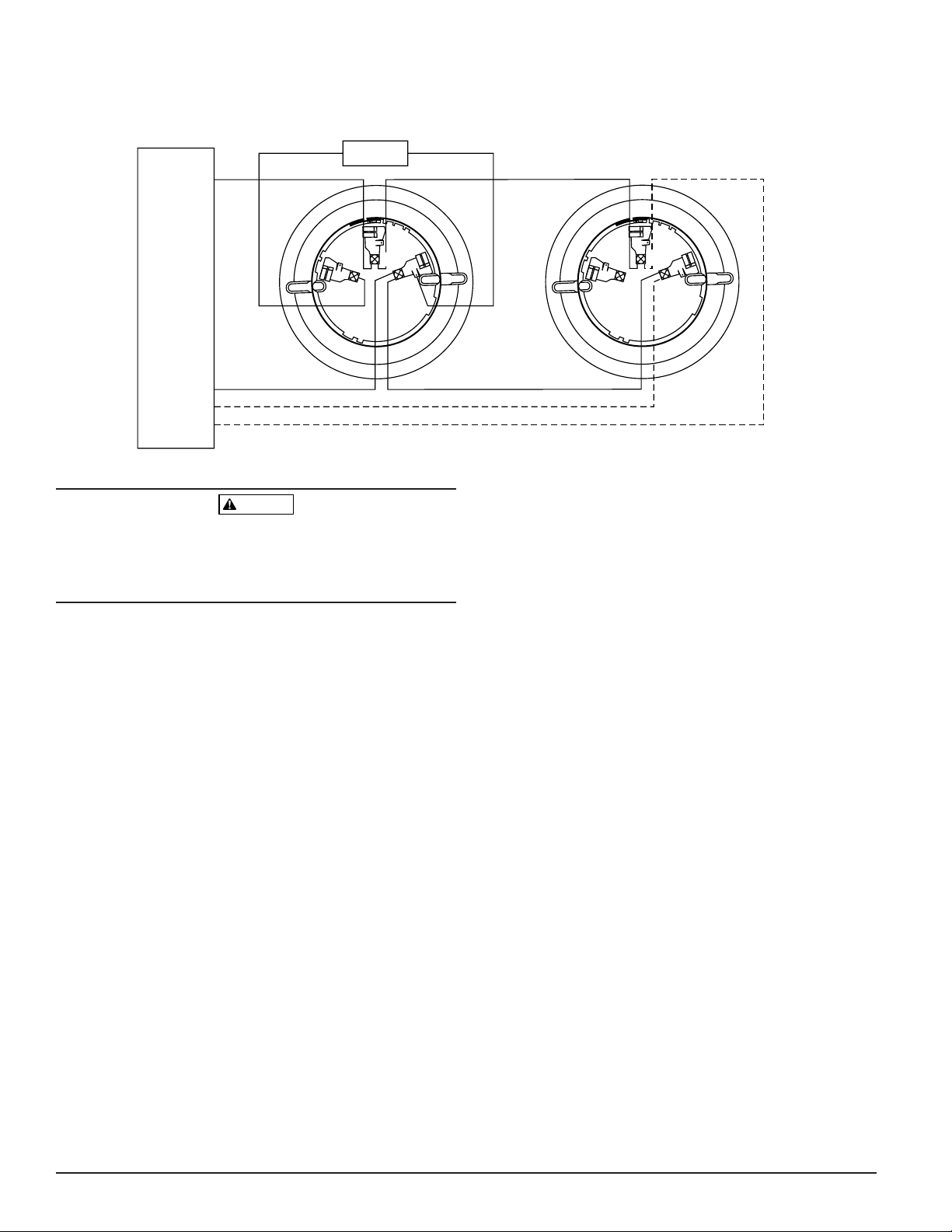
1. Wire the sensor base (supplied separately) per the
wiring diagram, see Figure 1.
2. Set the desired address on the sensor address switches,
see Figure 2.
3. Install the sensor into the sensor base. Push the sensor
into the base while turning it clockwise to secure it in
place.
4. After all sensors have been installed, apply power to the
control unit and activate the communication line.
5. Test the sensor(s) as described in the TESTING section
of this manual.
Page 2
D200-08-00 2 I56-0001-01R
Dust covers provide limited protection against airborne
dust particles during shipping. Dust covers must be
removed before the sensors can sense smoke. Remove sensors prior to heavy remodeling or construction.
Testing
Before testing, notify the proper authorities that the system
is undergoing maintenance, and will temporarily be out of
service. Disable the system to prevent unwanted alarms.
All sensors must be tested after installation and periodically thereafter. Testing methods must satisfy the Authority
Having Jurisdiction (AHJ). Sensors offer maximum performance when tested and maintained in compliance with
NFPA 72.
The sensor can be tested in the following ways:
A. Functional: Magnet Test (P/N M02-04-01 or M02-09-00)
This sensor can be functionally tested with a test magnet. The test magnet electronically simulates smoke in
the sensing chamber, testing the sensor electronics and
connections to the control panel.
1. Hold the test magnet in the magnet test area as shown
in Figure 3.
2. The sensor should alarm the panel.
Two LEDs on the sensor are controlled by the panel to
indicate sensor status. Coded signals, transmitted
from the panel, can cause the LEDs to blink, latch on,
or latch off. Refer to the control panel technical documentation for sensor LED status operation and
expected delay to alarm.
CAUTION
A78-2461-00
3
2
1
3
2
1
+
–
–
+
UL LISTED COMPATIBLE
CONTROL PANEL
OPTIONAL RETURN LOOP
REMOTE ANNUNCIATOR
+–
B. Smoke Entry: Aerosol Generator (Gemini 501)
Smoke entry testing should be performed immediately
following the magnet test. Magnet test initiates an
approximately 10 minute period when the detector’s signal processing software routines are not active. Failure to
first perform the magnet test will introduce a time delay
before the detector alarms.
The GEMINI model 501 aerosol generator can be used
for smoke entry testing. Set the generator to represent
4%/ft. to 5%/ft. obstruction as described in the GEMINI 501 manual. Using the bowl shaped applicator, apply
aerosol until the panel alarms.
C. Direct Heat Method (Hair Dryer of 1000-1500 watts)
A hair dryer of 1000-1500 watts should be used to test
the thermistors. Direct the heat toward either of the two
thermistors, holding the heat source approximately 12
inches from the detector in order to avoid damaging the
plastic housing. The detector will reset only after it has
had sufficient time to cool. Make sure both thermistors
are tested individually.
A sensor that fails any of these tests should be cleaned as
described under CLEANING, and retested. If the
sensor fails after cleaning, it must be replaced and returned
for repair.
When testing is complete, restore the system to normal
operation and notify the proper authorities that the
system is back in operation.
Figure 1. Wiring diagram:
Page 3

D200-08-00 3 I56-0001-01R
A78-2462-05
A78-2463-24
Cleaning
It is recommended that the detector be removed from its
mounting base to facilitate cleaning. The detector is
cleaned as follows:
NOTE: Before removing the detector, notify the proper
authorities that the smoke detector system is
undergoing maintenance and will be temporarily
out of service. Disable the zone or system undergoing maintenance to prevent unwanted alarms.
1. Remove the detector cover by prying away the four
side tabs with a small-bladed screwdriver, and then
pulling the cover from the base.
2. Vacuum the screen carefully without removing it. If
further cleaning is required continue with Step 3, otherwise skip to Step 8.
3. Remove the screen assembly by pulling it straight out
(see Figure 4).
4. Remove the sensing chamber cover by pulling it
straight out.
5. Clean the vaned chamber piece by vacuuming or
blowing out dust and particles.
6. Replace the sensing chamber cover, aligning the arrow
on the top with arrow on the printed circuit board.
7. To replace the screen, place it over the chamber
assembly, turning it until it snaps into place.
8. Replace the cover using the LEDs to align the cover
and then gently pushing it until it locks into place.
Make sure thermistors do not become bent under
cover.
9. Reinstall the detector.
10. Test the detector as described in TESTING.
11. Reconnect disabled circuits.
12. Notify the proper authorities that the system is back
on line.
A78-2460-02
Figure 2. Rotary decade address switches:
Figure 3. Test magnet position:
Figure 4. Sensor assembly:
0
8
7
1
2
3
4
5
6
9
0
8
7
1
2
3
4
5
6
9
PAINTED
SURFACE
T
T
E
S
E
T
MAGN
MAGNET TEST
MARKER
TEST
MAGNET
PAINTED
SURFACE
T
O
N
O
D
LED STATUS
INDICATORS
T
N
I
A
P
SENSOR
COVER
COVER REMOVAL
TABS
SENSOR
SCREEN
SENSING
CHAMBER
COVER
SENSING
CHAMBER
Page 4

D200-08-00 4 I56-0001-01R
©
System Sensor 2000
Three-Year Limited Warranty
System Sensor warrants its enclosed smoke detector to be free from
defects in materials and workmanship under normal use and service for a
period of three years from date of manufacture. System Sensor makes no
other express warranty for this smoke detector. No agent, representative,
dealer, or employee of the Company has the authority to increase or alter
the obligations or limitations of this Warranty. The Company’s obligation
of this Warranty shall be limited to the repair or replacement of any part
of the smoke detector which is found to be defective in materials or workmanship under normal use and service during the three year period commencing with the date of manufacture. After phoning System Sensor’s toll
free number 800-SENSOR2 (736-7672) for a Return Authorization number,
send defective units postage prepaid to: System Sensor, Repair
Department, RA #__________, 3825 Ohio Avenue, St. Charles, IL 60174.
Please include a note describing the malfunction and suspected cause of
failure. The Company shall not be obligated to repair or replace units
which are found to be defective because of damage, unreasonable use,
modifications, or alterations occurring after the date of manufacture. In no
case shall the Company be liable for any consequential or incidental damages for breach of this or any other Warranty, expressed or implied whatsoever, even if the loss or damage is caused by the Company’s negligence
or fault. Some states do not allow the exclusion or limitation of incidental
or consequential damages, so the above limitation or exclusion may not
apply to you. This Warranty gives you specific legal rights, and you may
also have other rights which vary from state to state.
FCC Statement
This device complies with part 15 of the FCC Rules. Operation is subject to the following two conditions: (1) This device may not cause harmful interference, and (2) this device must accept any interference received, including interference that may cause undesired operation.
Note: This equipment has been tested and found to comply with the limits for a Class B digital device, pursuant to Part 15 of the FCC Rules. These
limits are designed to provide reasonable protection against harmful interference in a residential installation. This equipment generates, uses
and can radiate radio frequency energy and, if not installed and used in accordance with the instructions, may cause harmful interference to
radio communications. However, there is no guarantee that interference will not occur in a particular installation. If this equipment does cause
harmful interference to radio or television reception, which can be determined by turning the equipment off and on, the user is encouraged to
try to correct the interference by one or more of the following measures:
– Reorient or relocate the receiving antenna.
– Increase the separation between the equipment and receiver.
– Connect the equipment into an outlet on a circuit different from that to which the receiver is connected.
– Consult the dealer or an experienced radio/TV technician for help.
Please refer to insert for the Limitations of Fire Alarm Systems
 Loading...