

Page 1
M
S
E
0832
0832-CPD-0199
INSTALLATION AND MAINTENANCE INSTRUCTIONS FOR MODEL 2251EIS INTRINSICALLY
SAFE ANALOGUE ADDRESSABLE PHOTO ELECTRONIC SMOKE SENSOR
Before installing the sensor, please thoroughly read System Sensor Europe’s “Guide to Intelligent Fire Systems”. This manual includes detailed
information on sensor spacing, placement, zoning and special applications. Copies of this manual are available at no charge from System
Sensor.
GENERAL DESCRIPTION
Model 2251EIS is an intrinsically safe smoke detector that combines a photo electronic sensing chamber with analogue addressable
communications and is for use in hazardous areas where potentially explosive atmospheres are likely to arise. The classification of equipment
required must be confirmed with your responsible authority. The sensor communicates via a dedicated Galvanic Isolator Barrier with an IST200
T ranslator Module wich relays the data to the Controls P anel. Rotary decade switches are provided for setting the sensors address.
T wo LEDs on each sensor provide a local 360° visible sensor indication. These LEDs can be latched on by code command from the control panel
for local alarm indication. They are unlatched to the normal condition by code command, and may also be set to blink in normal operation.
SPECIFICATIONS
Operating V oltage Range 17 to 24 VDC
Max. Avg. Standby Current 330 µA (One communication every 5 sec. With
Max. Alarm Current (LED on) 4.2 mA @ 24 VDC
Operating Humidity Range: 5% to 93% Relative Humidity , Non-Condensing
Operating Temperature Range: -10°C to 40°C
Maximum Air Velocity 0.34m/s (4000ft/min)
Height: 43 mm installed in B501 base
Diameter: 102 mm installed in B501 base
Weight: 110 g
Intrinsic Safety Rating: II 1 G EEx ia IIB T5
This detector has been independently tested and certified to EN54 part 7: 2000 and
BASEEFA appro ved for intrinsic safety.
LED blink enabled)
ACCESSORIES (Available Separately from System Sensor)
IST200 T r anslator Module May drive up to 15 2251EIS sensors
Pepperl and Fuchs Y72221 Dedicated Galvanic Isolator Barrier for 2251EIS detectors to drive up to 15 2251EIS sensors
WIRING GUIDE
Refer to the installation instructions supplied with the IST200 Translator Module, and B501 Base for wiring details.
Note: All wiring must conform to applicable local and national codes and regulations.
Ve rify that all sensor bases are installed and that polarity of the wiring is correct at each base.
WARNING
Disconnect loop power before installing sensors.
SENSOR INSTALLATION
1. Set the sensor address (see figure 1) by using a flat blade screwdriver to turn the two rotary switches, selecting the desired number
between 01and 99. Record the address on the label attached to the base.
2. Insert the sensor into the base and rotate it clockwise with gentle pressure until it drops into place.
3. Continue to rotate the sensor until it locks into the base.
4. After all the sensors have been installed, apply power to the system.
5. Test the sensor as described under TESTING.
6. Reset the sensor by communication command from the panel.
Tamper -Resistance.
Model 2251EIS includes a feature that, when activated, prevents removal of the sensor without the use of a tool. Refer to the installation
instructions for the sensor base for details of how to use this feature.
CAUTION
Dust covers help to protect units during shipping and when first installed. They are not intended to provide complete protection
against contamination therefore sensors should be removed before construction, major re-decoration or other dust producing work
is started. Dust covers must be removed before system can be made operational.
MAINTENANCE
Before cleaning, notify the proper authorities that the system is undergoing maintenance and will be temporarily out of service. Disable the
system to prevent unwanted alarms.
1. Remove the sensor to be cleaned from the system.
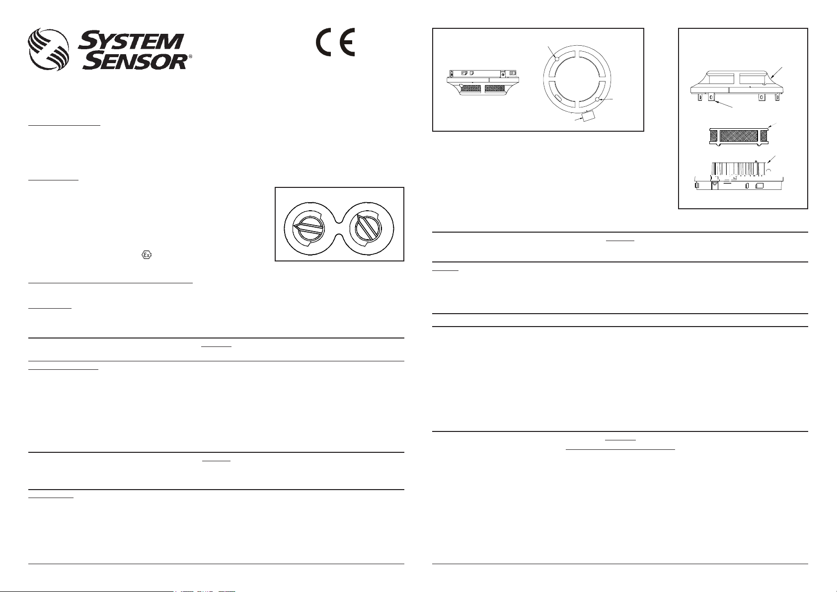
2. Remove the sensor cover. Use a small flat blade screwdriver to gently release each of the four cover removal tabs that hold the cover in
place (see figure 3).
3. Vacuum the outside of the screen carefully without removing it.
4. Remove the sensor screen. Pull the screen straight away from the sensing chamber until it snaps out of place. Replacement screens are available.
5. Remove the chamber cover by pulling it gently away from the sensing chamber until it snaps out of place.
D200-50-00 Pittway Tecnologica S.r.l., Via Caboto 19/3, 34147 Trieste, Italy © System Sensor 2008 I56-2626-0051
Figure 1: Rotary Decade Address Switch
7
8
6
55
9
87
69
44
3
2
1
0
3
2
1
0
UNITSTENS
Figure 2: Test Magnet Position
6. Use a vacuum cleaner and/or clean, compressed air to remove dust and debris from
the sensing chamber and sensing chamber cover.
7. Re-install the sensing chamber cover by aligning the arrow moulded on the cover with
the arrow printed on the circuit board and sliding the cover over the chamber, gently
pressing it home until it until it snaps into place.
8. Re-install or replace the sensing chamber screen by sliding it over the sensing
chamber. Rotate the screen until the locating tabs on the bottom rim locate in the
cutouts in the chamber base, and the top of the screen is flush with the top of the
chamber.
9. Re-install the sensor cover. Use the cover removal tabs and LEDs to align the cover
with the sensor. Snap the cover into place.
10 . When all sensors have been cleaned, restore power to the loop and test the sensor(s) as described under TESTING.
LED
INDICATOR
TEST
MAGNET
LED
INDICATOR
Figure 3: Sensor Assembly
COVER
COV ER
REMOVAL TABS
REMO VAL T ABS
SENSOR
COVER
SENSOR
SEN
SCREEN
SCR
SENS
SENSING
CHA
CHAMBER
CAUTION
The Detector has a plastic enclosure that may present an electrostatic risk and must not be installed in a position where it may be
subject to a high dust-laden air flow. Clean only with a damp cloth and do not rub.
TESTING
Sensors must be tested after installation and following periodic maintenance. However, before testing, notify the proper authorities that the smoke
detector system is undergoing maintenance and the system will be temporarily out of service. Disable the zone or system undergoing
maintenance to prevent unwanted alarms.
In addition, check to ensure that the LEDs blink (if this feature is operational under software command). If they do not, power has been lost to the
sensor (check the wiring) if it is defective (return it for repair).
IMPORT ANT : If testing is carried out using non-intrinsicall y saf e methods, it must be conducted outside the hazar dous area.
T est the sensors as follows:
Magnet Test (Optional Test Magnet Part No M02-24)
1. Test the sensor by positioning the test magnet (model M02-24-optional) against the sensor body approximately 2cm from LED1 in the
direction of the metering socket as shown in figure 2.
2. The red LED’s on the detector should latch into alarm within 30 seconds, and the control panel should activate into alarm.
Smoke method
1. Using generated smoke, or synthetic smoke aerosol from an approved manufacturer such as No Climb Products Ltd, subject the detector to
controlled amounts of smoke in accordance with local codes of practice and manufacturer recommendations.
2. The red LED’s on the detector should latch into alarm within 30 seconds, and the control panel should activate into alarm.
After completion of the test notify the proper authorities that the system is operational.
Sensors that fail this test should be cleaned as described under MAINTENANCE and retested. If the sensors still fail this test they should be
returned for repair.
WARNING
LIMITATIONS OF SMOKE DETECTORS
This smoke detector is designed to activate and initiate emergency action, but will do so only when used in conjunction with other equipment.
Smoke detectors will not work without power.
Smoke detectors will not sense fires which start where smoke does not reach the detectors. Smoke from fires in chimneys, in walls, on roofs, or
on the other side of closed doors may not reach the smoke detector and trigger the unit.
A detector may not detect a fire developing on another level of a building. For this reason, detectors should be located on every level for a building.
Smoke detectors also have sensing limitations. Ionisation detectors off er a broad range fire-sensing capability, but they are better at detecting
fast, flaming fires than slow smouldering fires. Photo electronic detectors sense smouldering fires better than flaming fires. Because fires develop
in different ways, and are often unpredictable in their growth, neither type of detector is necessarily better and a given detector may not always
provide warning of a fire. In general, detectors cannot be expected to provide warnings for fires resulting from inadequate fire protection practices,
violent explosions, escaping gas, improper storage of flammable liquids like cleaning solvents, other safety hazards, or arson. Smoke detectors
used in high air velocity conditions may fail to alarm due to dilution of smoke densities created by such frequent and rapid air exchanges.
Additionally, high air v elocity environments may create increased dust contamination, demanding more frequent maintenance.
Page 2

Smoke detectors cannot last forever. Smoke detectors contain electronic parts. Even though detectors are made to last over 10 years, any of
these parts could fail at any time. Therefore, test your smoke detector system at least semi-annually. Clean and take care of your smoke
detectors regularly. Taking care of the fire detection system you have installed will significantly reduce your product liabili ty risks.
2251EIS System Diagram
SAFE AREA
Safe area apparatus, which is
unspecified except that it must not
be supplied from or contain under
normal or abnormal conditions a
source of potential with respect to
earth in excess of 253 Vrms or 253
VDC
Shunt Zener
Diode Safety
Barrier or
Isolation
Barrier (see
Note 1.)
SEE (NOTE 2)
HAZARDOUS AREA
TO NEXT
DETECTOR(S)
(NOTE 5)
0832
0832-CPD-0199
DECLARATION OF CONFORMITY
Date of Issue: 18/06/2008
Manufacturer: Pittway Tecnologica S.r.l.
Via Caboto 19/3
34147 Trieste
Italy
2 (+)
3
Terminals 1 and 2 (B501 Base)
Group Capacitance Inductance L/R Ratio
IIB 0.65 12.60 210
IIA 2.15 33.60 444
Notes:
1. Any single channel shunt zener diode safety barrier or single channel of a dual channel shunt zener diode safety barrier certified
2. The capacitance and either inductance or inductance/resistance (L/R) ratio of the cable connected to the hazardous area
3. The installation must comply with the appropriate national installation requirements, e.g. in the U.K. to BSEN60079-14: 1997.
4. The electrical circuit in the hazardous area must be capable of withstanding an A.C. test voltage of 500 VRMS to earth or frame
5. The system must be marked with a durable label. The label should appear on or adjacent to the principle item of electrical
µF mH µH/OHM
T able 1
by Baseefa or any EEC approved certification body to [EEx ia] IIC having the following or lower output parameters:
Uz = 28V; Imax: out = 93.3 mA; Wmax: out = 0.66 W
In any safety barrier used, the output current must be limited by a resistor "R", such that Imax:out = Uz/R. Or any of the
following isolation barriers may be used:
One channel from: P & F Smart Fire Detector Isolator Type KFDO-CS-Ex2.54-Y2222 (BAS00ATEX7087X)
terminals of barrier must not exceed the values shown in Table 1.
of the equipment, for a period of one minute without breakdown. This note does not apply when using an isolation barrier.
equipment in the system or at the interface between intrinsically safe and non intrinsically safe circuits. This should show
Baseefa 03Y0182 and SYST or System.
P & F Smart Fire Detector Isolator T ype KFDO-CS-Ex1.54-Y72221 (BAS00ATEX7087x)
1 (-)
(B501 Base)
Model 2251EIS
Smoke Detector
II1G EEx ia IIB T5
Baseefa03ATEX0157X
B501 Pins Connection
1 - Vin, - Vout
2 + Vin, + Vout
3 No Connection
Table 2
R12-172-00, REV E
Product: 2251EIS
Mounting Bases: B501
Description: Intrinsically safe analogue addressable photoelectronic
smoke detector
We hereby declare that the product identified above meets the requirements of the of the EMC
Directive 89/336/EEC amended by 92/31/EEC, 93/68/EEC, 93/97/EEC and the directives
listed below. It therefore qualifies for free movement within markets comprising the
European Union (EU) and the European Economic Area (EEA).
Directive EU Construction Products ATEX 94/9/EEC
Directive 89/106/EEC
Standard EN54-7:2000 EN 50014: 1997 + Amends 1 &2
EN 50020: 2002 EN 50284: 1999
Notified Body BRE-LPCB BASEEFA (2001) Ltd
Address Garston Rockhead Business Park
Watford Staden Lane Buxton
WD25 9XX Derbyshire SK17 9RZ
Notified Body # 0832 1180
Certificate # 0832-CPD-0199 Baseefa03 ATEX 0157X
Rating --- II 1 G EEx ia II B T5
Please refer to control panel installation instructions for specific barrier/control panel compatibility information.
CAUTION
D200-50-00 Pittway Tecnologica S.r.l., Via Caboto 19/3, 34147 Trieste, Italy © System Sensor 2008 I56-2626-0052
Alfonso Paribelli
Plant Manager
Pittway Tecnologica S.r.l.
Via Caboto 19/3
34147 Trieste Italy
Telephone: +39 040 9490 111
Fax: +39 040 382137
 Loading...