

Page 1
22051EISE
102 mm
47 mm
44
0
2
3
1
0
2
3
1
6
7
5 5
9
8
6 9
87
0832
0832-CPD-0199
B501AP
60°C
112.5g
-20°C
T4
INSTALLATION AND MAINTENANCE INSTRUCTIONS
EN
FOR MODEL 22051EISE INTRINSICALLY SAFE
INTELLIGENT PHOTO ELECTRONIC SMOKE SENSOR
Before installing the sensor, please thoroughly read System Sensor Europe’s “Guide
to Intelligent Fire Systems”. Copies of this manual are available at no charge from
System Sensor.
GENERAL DESCRIPTION
Model 22051EISE is an intrinsically safe smoke detector that combines a photo
electronic sensing chamber with analogue addressable communications and is for use
in hazardous areas where potentially explosive atmospheres are likely to arise. The
classification of equipment required must be confirmed with your responsible authority.
The sensor communicates via a dedicated Galvanic Isolator Barrier with an IST200
Translator Module which relays the data to the Control Panel. Rotary decade switches
are provided for setting the sensor address.
Two LEDs on each sensor provide a local 360° visible sensor indication.
SPECIFICATIONS
Operating Voltage Range: 15 to 24 VDC
Max. Avg. Standby Current: 220 µA @20 VDC (One communication every 5
Max. Alarm Current (LED on): 3 mA @ 24 VDC
Operating Humidity Range: 10% to 93% Relative Humidity, Non-Condensing
Intrinsic Safety Rating: Ex ia IIC T5, T4
This detector has been independently tested and certified to EN54 part 7: 2000 and
BASEEFA approved for intrinsic safety.
ACCESSORIES (Available Separately from System Sensor)
IST200 Translator Module May drive up to 15 22051EISE sensors
Pepperl and Fuchs Y72221 Dedicated Galvanic Isolator Barriers for
WIRING GUIDE
Refer to the installation instructions supplied with the IST200 Translator Module, and
B501AP Base for wiring details.
Note 1: All wiring must conform to applicable local and national codes and regulations.
Note 2: Verify that all sensor bases are installed and that polarity of the wiring is
correct at each base.
Disconnect loop power before installing sensors. Notify proper authorities.
SENSOR INSTALLATION
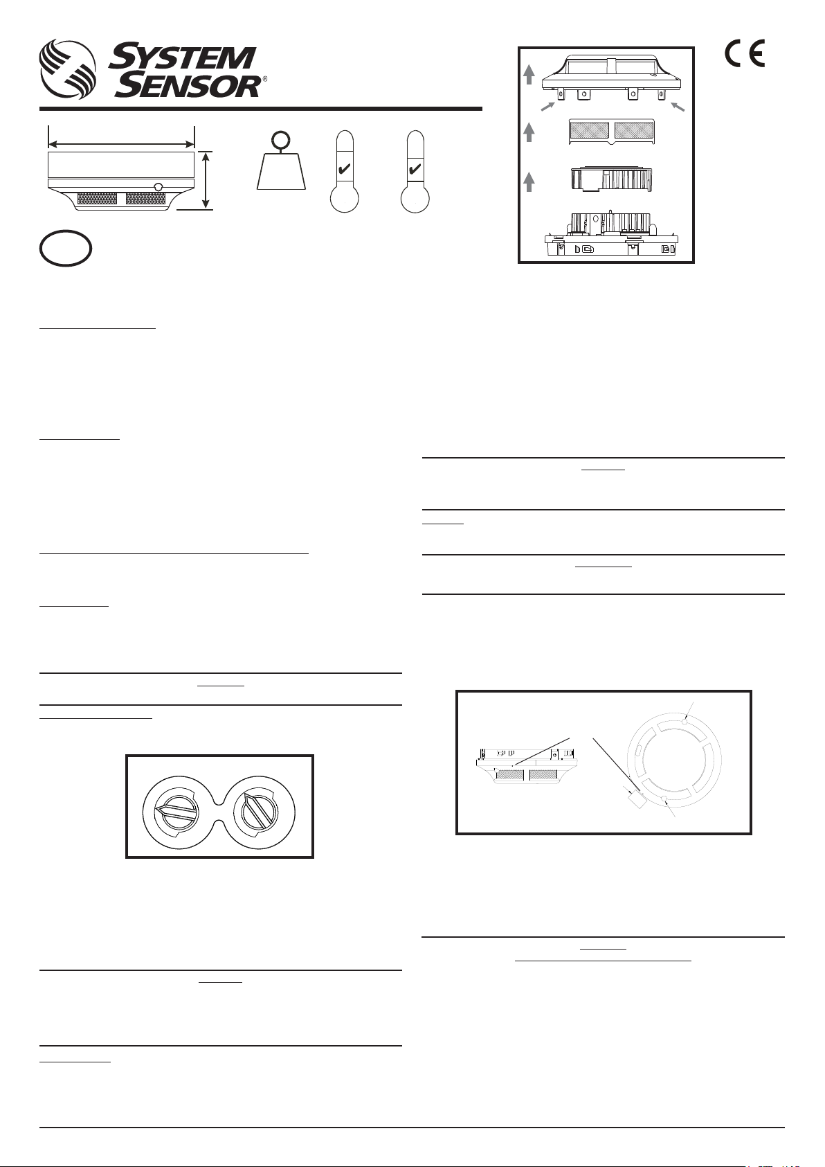
1. Set the sensor address (see figure 2) by turning the two rotary switches, selecting a
number between 01and 99. Record the address on the label attached to the base.
Figure 2: Rotary Decade Address Switch
sec. With LED blink enabled)
22051EISE (drive up to 15 sensors).
WARNING
40°C
-20°C
T5
4. Remove the sensor screen. Pull the screen straight away from the sensing chamber
until it snaps out of place.
5. Remove the chamber cover by pulling it gently away from the sensing chamber until
it snaps out of place.
6. Use a vacuum cleaner and/or clean, compressed air to remove dust and debris
from the sensing chamber and sensing chamber cover.
7. Re-install the sensing chamber cover by aligning the arrow moulded on the cover
with the arrow printed on the circuit board and sliding the cover over the chamber,
gently pressing it home until it snaps into place.
8. Re-install the sensing chamber screen by sliding it over the sensing chamber.
Rotate the screen until the locating tabs on the bottom rim locate in the cutouts in
the chamber base, and the top of the screen is flush with the top of the chamber.
9. Re-install the sensor cover. Use the cover removal tabs and LEDs to align the cover
with the sensor. Snap the cover into place.
10. When all sensors have been cleaned, restore power to the loop and test the sensor(s)
as described under TESTING.
CAUTION
The Detector has a plastic enclosure that may present an electrostatic risk and
must not be installed in a position where it may be subject to a high dust-laden
air flow. Clean only with a damp cloth and do not rub.
TESTING
Sensors must be tested after installation and following periodic maintenance. Disable
the zone or system undergoing maintenance to prevent unwanted alarms.
IMPORTANT
If testing is carried out using non-intrinsically safe methods, it must be
conducted outside the hazardous area.
Test the sensors as follows:
Magnet Test Method
1. Test the sensor by positioning the test magnet (model M02-04-00 optional) against
the sensor body approximately 2cm from LED 1, indicated by a mark on the detector
cover as shown in figure 3.
2. Both LED’s on the detector should latch into alarm within 30 seconds, activating the
control panel.
Figure 3: Test Magnet Position
Mark on Cover
Test Magnet
Figure 1: Cleaning
the Sensor
LED 2
TENS
2. Insert the sensor into the base and rotate it clockwise until it locks into place.
3. After all the sensors have been installed, apply power to the system.
4. Test the sensor as described under TESTING.
5. Reset the sensor by communication command from the panel.
Tamper-Resistance.
Model 22051EISE includes a feature that, when activated, prevents removal of the
sensor without the use of a tool. Refer to the installation instructions for the sensor
base for details of how to use this feature.
Dust covers help to protect units during shipping and when first installed.
They are not intended to provide complete protection against contamination
therefore sensors should be removed before construction, major re-decoration
or other dust producing work is started. Dust covers must be removed before
MAINTENANCE
Before cleaning, disable the system to prevent unwanted alarms:
1. Remove the sensor to be cleaned from the system.
2. Gently release each of the four cover removal tabs that hold the cover in place (see
figure 1) and remove the cover.
3. Vacuum the outside of the screen carefully without removing it.
system can be made operational.
CAUTION
UNITS
LED 1
Smoke Method
1. Using generated smoke, or synthetic smoke aerosol from an approved manufacturer
such as No Climb Products Ltd, subject the detector to controlled amounts of smoke
in accordance with local codes of practice and manufacturer recommendations.
2. Both LED’s on the detector should latch into alarm within 30 seconds, activating the
control panel.
After completion of the test notify the proper authorities that the system is operational.
WARNING
LIMITATIONS OF SMOKE DETECTORS
Smoke detectors must be used in conjunction with compatible equipment.
Smoke detectors will not sense fires which start where smoke does not reach the
detectors.
A detector may not detect a fire developing on another level of a building.
Smoke detectors also have sensing limitations. Consideration must be made of the
environment when selecting fire detectors.
Smoke detectors cannot last forever. Smoke detectors contain electronic par ts. Even
though detectors are made to last over 10 years, any of these parts could fail at any
time. Therefore, test your smoke detector system at least semiannually. Clean and take
care of your smoke detectors regularly. Taking care of the fire detection system you
have installed will significantly reduce your product liability risks.
Pittway Tecnologica Srl, Via Caboto 19/3, 34147 Trieste, ITALY I56-3310-003D200-51-00
Page 2
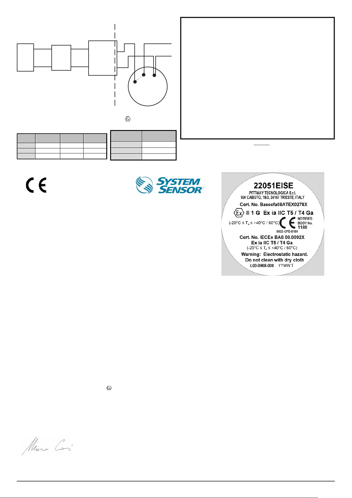
22051EISE System Diagram
0.083 4.2 55
0.65 12.6 210
2.15 33.6 444
SAFE AREA
Control
Panel
Safe area apparatus, which is
unspecified except that it must not be
supplied from or contain under normal
or abnormal conditions a source of
potential with respect to earth in excess
of 253 Vrms or 253 VDC
Maximum Permissible Capacitance,
Inductance and Impedance Figures Across
Terminals 1 and 2 on a B501AP Base
Capacitance µFInductance mHL/R Ratio
Group
IIC
IIB
IIA
IST200
Translator
Module
Table 1 Table 2
Shunt Zener
Diode Safety
Barrier or
Isolation
Barrier (see
Note 1.)
µH/Ohm
HAZARDOUS AREA
(See Note 2)
To Next
Detector(s)
4 (+)
1 (-)
2 (+)
B501AP
2 & 4 linked in base
22051EISE
Smoke Detector
II1G Ex ia IIC T5, T4
Baseefa08ATEX0278X
B501AP Pins Connection
1
2
4
-V IN, -V OUT
+V IN
+V OUT
Notes:
1. Any single channel shunt zener diode safety barrier or single channel of a
dual channel shunt zener diode safety barrier certified by Baseefa or any EEC
approved certification body to [EEx ia] IIC having the following or lower output
parameters:
Uz = 28V; Imax: out = 93.3 mA; Wmax: out = 0.66 W
In any safety barrier used, the output current must be limited by a resistor “R”,
such that Imax:out = Uz/R. Or any of the following isolation barriers may be
used:
P & F Smart Fire Detector Isolator Type KFDO-CS-Ex1.54-Y72221
One channel from: P & F Smart Fire Detector Isolator Type KFDO-CS-Ex2.54-
Y72222 (BAS00ATEX7087X)
2. The capacitance and either inductance or inductance/resistance (L/R) ratio of
the cable connected to the hazardous area terminals of barrier must not exceed
the values shown in Table 1.
3. The installation must comply with the appropriate national installation
requirements, e.g. in the U.K. to BSEN60079-14: 1997.
4. The electrical circuit in the hazardous area must be capable of withstanding
an A.C. test voltage of 500 VRMS to earth or frame of the equipment, for a
period of one minute without breakdown. This note does not apply when using
an isolation barrier.
R12-172-00, REV G
Please refer to control panel installation instructions for specific barrier/control panel
CAUTION
compatibility information.
0832
0832-CPD-0199
EC DECLARATION OF CONFORMITY
Date of issue: 07 November 2012
Pittway Tecnologica Srl
Manufacturer:
Product: 22051EIS
Bases: B501, B501AP
Description:
We hereby declare that the product identified above meets the requirements of the following EC
Directives and therefore qualify for free movement within markets comprising the European Union
(EU) and the European Economic Area (EEA):
EMC Directive 2004/108/EC
EU Construction Products Directive, 89/106/EEC
Conforms to: EN54 - 7: 2000 + A1: 2002 + A2:2006
Notified Body: BRE - LPCB
Notified Body Number: 0832
EC Certificate Number 0832-CPD-0199
ATEX 94/9/EEC
Conforms to:
Notified Body: Baseefa
Notified Body Number: 1180
Certificate Number Baseefa08ATEX0278X
Rating
For and on behalf of
Pittway Tecnologica S.r.l.
Marco Corti
Plant Manager
Via Caboto 19/3
34147 TRIESTE
Italy
E
Intrinsically Safe Analogue addressable photoelectric smoke detector
EN60079-0: 2006, EN60079-11: 2007
EN60079-26:2007
II 1G Ex ia IIC T5 / T4 Ga (-20°C ≤Ta≤ 40°C/60°C)
Pittway Tecnologica S.r.l.
a socio unico
Via Caboto 19/3
34147 TRIESTE (Italy)
Tel: +39-040-9490111
Fax: +39-040-382137
N. IVA IT 00744320326
Reg. Impr. TS n. 10331 Trib. TS
R.E.A. N. 97799
Cap.Soc. € 1.368.619,00 int. vers.
P.IVA e Cod. Fisc. 00744320326
Page 3

22051EISE
102 mm
47 mm
44
0
2
3
1
0
2
3
1
6
7
5 5
9
8
6 9
87
0832
0832-CPD-0199
B501AP
60°C
112.5g
-20°C
T4
INSTALLATIONS- UND WARTUNGSANLEITUNG FÜR
D
MODELL 22051EISE EIGENSICHERER INTELLIGENTER
OPTISCHER RAUCHMELDER
Bevor Sie mit der Installation des Brandmelders beginnen, lesen Sie bitte sorgfältig die
Anleitung zum Umgang mit intelligenten Brandmeldesystemen. Kopien dieser Anleitung
sind kostenlos bei System Sensor erhältlich.
ALLGEMEIN
Das Modell 22051EISE ist ein eigensicherer Rauchmelder, der eine optische
Sensorkammer mit einer analog adressierbaren Kommunikation verbindet und ist für
die Verwendung in Gefahrenbereichen, in denen mit einer explosiven Atmosphäre
gerechnet werden muss. Die Klassifizierung der erforderlichen Baugruppen muss den
Anforderungen der zuständigen Behörde entsprechen. Der Sensor kommunizier t über
eine geeignete galvanische Trennungsbarriere mit einem IST200 Übersetzermodul,
welches die Daten an das Bediengerät weiterleitet. Für die Einstellung der
Sensoradresse stehen Dekadendrehschalter zur Verfügung.
Die beiden LED ermöglichen eine optische Erkennung des Sensorzustandes im
Bereich von 360 Grad.
SPEZIFIKATION
Betriebsspannungsbereich: 15 bis 24 VDC
Maximaler Durchschnittsruhestrom: 220 µA bei 20 VDC (Datenkommunikation alle 5
Maximaler Strom im Alarmfall: 3 mA bei 24 VDC (LED ein)
Bereich der Luftfeuchtigkeit: 10% bis 93% relative Feuchte, ohne Betauung
Einstufung der Eigensicherheit: Ex ia IIC T5 (40o to -20oC), T4 (60o to -20oC)
Dieser Melder wurde unabhängig getestet und gemäß den Anforderungen für
Eigensicherheit der EN54 Teil 7 (2000) und BASEEFA zertifiziert.
ZUBEHÖR (Optional erhältlich von System Sensor)
IST200 Übersetzermodul: Für bis zu 15 Sensoren 22051EISE
Pepperl und Fuchs Y72221: Geeignete Galvanische Trennung für Sensor
VERDRAHTUNG
Weitere Verdrahtungsdetails finden Sie in der mitgelieferten Installationsanleitung des
IST200 Übersetzermoduls sowie des B501AP Meldersockels.
HINWEIS: Die Verdrahtung muss den lokalen und nationalen Normen und
Anforderungen entsprechen.
HINWEIS: Stellen Sie sicher, dass alle Meldersockel angeschlossen sind und die
Polarität der Verdrahtung an jedem Sockel korrekt ist.
Melder nur im spannungsfreien Zustand installieren. Beachten Sie die
SENSOR INSTALLATION
1. Stellen Sie die Sensoradresse durch Drehen der beiden Drehschalter ein (siehe
Abb.2). Wählen Sie eine Adresse zwischen 01 und 99. Notieren Sie die Adresse
auf dem Aufkleber am Meldersockel.
2. Setzen Sie den Melder in den Meldersockel und drehen ihn im Uhrzeigersinn bis er
einrastet.
3. Nachdem alle Melder installiert sind schalten Sie die Spannungsversorgung ein.
4. Prüfen Sie den Melder wie im Abschnitt PRÜFUNG beschrieben.
5. Setzen Sie den Sensor mit Hilfe des Kommunikationsbefehls der Bedienkonsole
zurück.
Abb. 2: Rotary Decade Address Switch
Sekunden bei aktivierter blinkender LED)
22051EISE (bis zu 15 Sensoren 22051EISE).
WARNUNG
dazugehörigen Vorschriften.
40°C
-20°C
T5
WARTUNG
Zur Vermeidung von Fehlalarmen sollte das System bzw. die entsprechende
Meldergruppe vor den Wartungsarbeiten abgeschaltet werden.
1. Entfernen Sie den zu reinigenden Sensor aus dem System.
2. Lösen Sie behutsam jede der vier Halterungen und entfernen Sie die Abdeckung
(siehe Abb.1).
3. Saugen Sie vorsichtig die Außenseite des Schutzgitters ab ohne dieses zu entfernen.
4. Entfernen Sie das Schutzgitter indem Sie es gerade von der Sensorkammer abziehen.
5. Ziehen Sie die Abdeckung der Sensorkammer vorsichtig ab.
6. Verwenden Sie einen Staubsauger oder saubere Druckluft um Staub und
Ablagerungen von der Sensorkammer oder dem Sensorgehäuse zu entfernen.
7. Befestigen Sie die Abdeckung der Sensorkammer wieder auf der Platine in dem
Sie die Abdeckung an den Markierungspfeilen ausrichten und mit leichtem Druck
einrasten lassen.
8. Führen Sie das Schutzgitter über die Sensorkammer und drehen es, bis die
Befestigungspunkte am unteren Rand in die Aussparungen des Meldersockels
passen und die Oberseite bündig mit der Sensorkammer abschließt.
9 Montieren Sie das Sensorgehäuse, in dem Sie es an den vier Befestigungspunkten
und den LED ausrichten und mit leichtem Druck einrasten lassen.
10 Nachdem alle Sensoren gereinigt wurden, schalten Sie die Ringleitung wieder ein
und prüfen Sie alle Sensoren auf Funktion wie im Abschnitt PRÜFUNG beschrieben.
Das Meldergehäuse besteht aus Kunststoff und kann elektrostatisch
aufgeladen werden. Der Melder sollte deshalb nicht in einer Umgebung
installiert werden, in der mit einer staubhaltigen hohen Luftbewegung
gerechnet werden kann. Reinigung nur mit einem feuchten
PRÜFUNG
Die ordnungsgemäße Funktion der installierten Melder ist zu prüfen. Weiterhin ist eine
regelmäßige Wartung erforderlich. Zur Vermeidung von Fehlalarmen schalten Sie die
entsprechende Meldergruppe oder das System ab. Vor Beginn der Servicearbeiten sind
die entsprechenden Interventionskräfte und Beteiligten über die Ausser-betriebnahme
der Anlage zu informieren. Schalten Sie die Meldergruppen und Alarm-weiterleitung ab,
um unerwünschte Alarmmeldungen während der Wartung zu vermeiden.
Bei Prüfungen, die nicht den Methoden für eigensichere Baugruppen
entsprechen, muss die Durchführung außerhalb des
Prüfen Sie den Melder wie folgt:
Magnet Test (Option, Artikel-Nr. M02-04-00)
1. Um den Melder zu prüfen halten Sie den Testmagnet in einer Entfernung von ca.
2cm zur LED 1 direkt an die Markierung am Meldergehäuse (siehe Abb.3).
2. Beide LED sollten innerhalb von 30 Sekunden leuchten und die Alarmauslösung
lokal und an der Brandmelderzentrale anzeigen.
LED 2
ACHTUNG
Tuch ohne Scheuern.
WICHTIG:
Gefahrenbereiches erfolgen.
Abb.3: Position des Testmagneten
Abb.1:
Reinigung des
Rauchmelders
TENS
UNITS
Sabotageschutz / Entnahmesicherung
Der Meldersockel verfügt über eine Entnahmesicherung die das Entfernen des
Brandmelders aus dem Sockel nur mit Hilfe eines Werkzeuges zulässt. Beachten Sie
die Installationshinweise des Meldersockels für detaillierte Informationen zu diesem
Leistungsmerkmal.
Der Melder ist werkseitig mit einem Staubschutz vor Verschmutzung während
des Transportes oder der Erstinstallation geschützt. Ein vollständiger Schutz
gegen eine Verunreinigung ist dadurch nicht gewährleistet. Deshalb sollten die
Melder vor Beginn von Konstruktions-, umfangreichen Dekorationsarbeiten
oder sonstigen Aktivitäten mit Staubentwicklung entfernt werden. Zur
ordnungsgemäßen Funktion ist der Staubschutz vor der Inbetriebnahme des
ACHTUNG
Melders abzunehmen.
LED 1
Gehäusemarkierung
Testmagnet
Rauchmethode
1. Mit einem geeigneten Prüfgas eines zugelassenen Herstellers (z.B. von No Climb
Products Ltd.) wird der Rauchmelder durch eine kontrollierte Prüfgasmenge
ausgelöst. Hierbei sind die Herstellerempfehlungen und die lokalen Anforderungen
zu beachten.
2. Beide LED des Rauchmelders sollten innerhalb von 30 Sekunden leuchten und die
Alarmauslösung lokal und an der Brandmelderzentrale anzeigen.
WICHTIG
Informieren Sie nach Abschluss der Prüfung alle beteiligten Stellen wieder
über die Inbetriebnahme des Systems.
Pittway Tecnologica Srl, Via Caboto 19/3, 34147 Trieste, ITALY I56-3310-003D200-51-00
Page 4

EINSCHRÄNKUNGEN VON RAUCHMELDERN
0.65 12.6 210
2.15 33.6 444
ACHTUNG
Rauchmelder müssen mit kompatiblen Anlagen verwendet werden.
Rauchmelder erkennen keine Entstehungsbrände deren Rauch die Melder nicht erreicht.
Ein Rauchmelder kann keine Feuerentwicklung in anderen Gebäudebereichen erken-
nen.
Rauchmelder haben auch Einschränkungen in der Auslösung. Bei der Auswahl von
Brandmeldern müssen die Umgebungsbedingungen berücksichtigt werden.
Rauchmelder haben keine ewige Lebensdauer, da sie elektronische Bauteile enthalten. Selbst wenn robuste Melder für eine Betriebszeit von über 10 Jahren ausgelegt
sind, können Bauteile jederzeit ausfallen. Testen Sie deshalb mindestens halbjährlich Ihr
Meldersystem. Reinigen und inspizieren Sie die Brandmelder regelmässig. Inspektionen
des Brandmeldesystems reduzieren erheblich das Produkthaftungsrisiko.
Maximal zulässige Kapazität, Induktivität
und Impedanz Figures Über Terminals 1
und 2 auf einer B501AP meldersockel
Gruppe
IIC
IIB
IIA
Kapazität
µF
0.083 4.2 55
Induktivität
mH
Tabelle 1
L/R Verhältnis
µH/Ohm
B501AP Pin Anschluss
1
2
4
Hinweise:
1. Jede Einkanal-Shunt Zener Dioden Sicherheitsbarriere oder 1-Kanal einer Zweikanal-Shunt
Zener Dioden Sicherheitsbarriere zertifiziert durch Baseefa oder einer EEC zugelassenen
Einrichtung für [EEx ia] IIC müssen den folgenden Parameter oder dieser Mindestanforderung
entsprechen:
Uz = 28V; Imax: out = 93,3 mA; Wmax: out = 0,66 W
Für jede Sicherheitsbarriere muss der Ausgangstrom durch einen Widerstand “R” wie folgt
begrenzt werden: Imax:out = Uz/R.
Anderenfalls sind folgende Trenneinrichtungen (Barrieren) einzusetzen:
P & F Smart Fire Detector Isolator Type KFDO-CS-Ex1.54-Y72221 (BAS00ATEX7087x)
Ein Kanal von: P & F Smart Fire Detector Isolator Type KFDO-CS-Ex2.54-Y2222
(BAS00ATEX7087X)
2. Die Kapazität und Induktivität bzw. Das Induktivität/Widerstandsverhältnis (L/R) der Kabel im
Gefahrenbereich zwischen den Anschlussklemmen) dürfen die in Tabelle 1 gezeigten Werte
nicht überschreiten.
3. Die Installation muss den nationalen Anforderungen und Auflagen, z.B. der DIN VDE 0166,
DIN EN 60079, entsprechen.
4. Die elektrische Schaltung in Gefahrenbereichen muss einer Prüfung mit Wechselspannung
von 500 V~eff nach Masse oder dem Gehäuserahmen der Baugruppe für mindestens eine
Minute standhalten. Entfällt beim Einsatz einer Sicherheitsbarriere.
5. Das System muss dauerhaft gekennzeichnet werden. Die Kennzeichnung muss sich auf
oder in unmittelbarer Nähe der Typenkennzeichnung der elektrischen Einrichtung oder auf
der Schnittstelle zwischen den eigensicheren und nicht eigensicheren Stromkreis befinden.
Auf der Kennzeichnung sollte die Bezeichnung „Baseefa 03Y0182 und SYST der System”
aufgebracht werden.
22051EISE System Diagramm
Sicherer Bereich
Brandmelderzentrale
Sicheres Gerät, für das keine weitere technische
Spezifikation vorliegt, außer dass unter allen
Bedingungen (normal und außergewöhnlich) die
Spannung innerhalb des Gerätes den Wert von
253 V~eff bzw. 253 V DC nicht überschreiten darf
und kein Bezug zum Erdungspotential besteht.
IST200
Übersetzermodul
-V IN, -V OUT
+V IN
+V OUT
Tabelle 2
Shunt Zener
Diode,
Sicherheitsbarriere oder
Galvanische
Trenneinrichtung
(siehe Hinweis 1.)
Gefahrenbereich (Ex-Bereich)
(siehe Hinweis 2)
Zu weiteren
Melder(n)
4 (+)
1 (-)
2 (+)
B501AP
22051EISE
Rauchmelder
II1G Ex ia IIC T5, T4
Baseefa08ATEX0278X
R12-172-00, REV G
Die Kompatibilität von speziellen Kombinationen für Sicherheitsbarriere und
ACHTUNG
Brandmelderzentrale entnehmen Sie bitte der Anleitung der Brandmelderzentrale.
 Loading...