

Page 1

INSTALLATION AND MAINTENANCE INSTRUCTIONS
2112/24S and 2112/24TS
3825 Ohio Avenue, St. Charles, Illinois 60174
Photoelectronic Smoke Detectors
Specifications
Diameter: 5.5 inches (140 mm)
Height (including mounting bracket): 1.9 inches (48 mm)
Weight: 5.3 oz. (150 g)
Operating Temperature Range
Model 2112/24S: 32° to 120°F (0° to 50°C)
Model 2112/24TS: 32° to 100° F (0° to 38° C)
Operating Humidity Range: 10% to 93% Relative Humidity, Noncondensing
Latching Alarm: Reset by momentary power interruption
Heat Sensor (2112/24TS only): 135° F Fixed Temperature Electronic Thermistor
Electrical Ratings
System Voltage (nominal): 12 or 24 VDC
Minimum: 8.5 VDC
Maximum: 35 VDC
Maximum Ripple Voltage: 30% of nom. Voltage (peak to peak)
Standby Current: 50 µA maximum
Alarm Current: 17 mA typical, 23 mA max. at 12V
19 mA typical, 25 mA max. at 24V
Reset Voltage: 0.8 VDC minimum
Reset Time: 0.3 seconds maximum
Start-up Time: 30 seconds maximum (after 60 sec. reset)
EOL Relay: A77-716B, 12/24 Volt
Alarm Initiation Contact Ratings
Resistive or Inductive Load (60% power factor)
Form A: 0.5A @ 30 VAC/DC
1-800-SENSOR2, FAX: 630-377-6495
Before Installing
Please thoroughly read the System Sensor manual I56-407,
Guide for Proper Use of System Smoke Detectors, which provides detailed information on detector spacing, placement,
zoning, wiring, and special applications. Copies of this
manual are available at no charge from System Sensor.
NOTICE: This manual shall be left with the owner/user of
this equipment.
IMPORTANT: This detector must be tested and maintained
following NFPA 72 requirements. The detector should be
cleaned at least once a year.
General Description
Model 2112/24S is a 4-wire photoelectronic smoke detector
that uses a state-of-the-art optical sensing chamber. This
detector is designed to provide open area protection. Model
2112/24TS features a restorable, built-in, fixed-temperature
(135° F) thermal detector.
D200-62-00 1 I56-932-12R
Installation of these detectors is simplified by the use of a
mounting bracket and a plug-in screw terminal block that
can be prewired to the system, allowing the detector to be
easily installed or removed for cleaning. The detector’s sensitivity can be tested in place using the MOD400R Test
Module.
An LED on the detector provides a local visual indication of
the detector’s status. If power is applied to the detector, and
it is functioning normally in standby mode within the listed
sensitivity ranges, the status LED blinks once every ten seconds. The LED also provides a visual indication that maintenance is required. If the LED stops blinking, the detector
is either not powered, out of the listed sensitivity range,
and/or unable to function properly. The test switch will not
operate if the detector is below the insensitive limit. The
LED will also latch on when the detector is in alarm.
Page 2
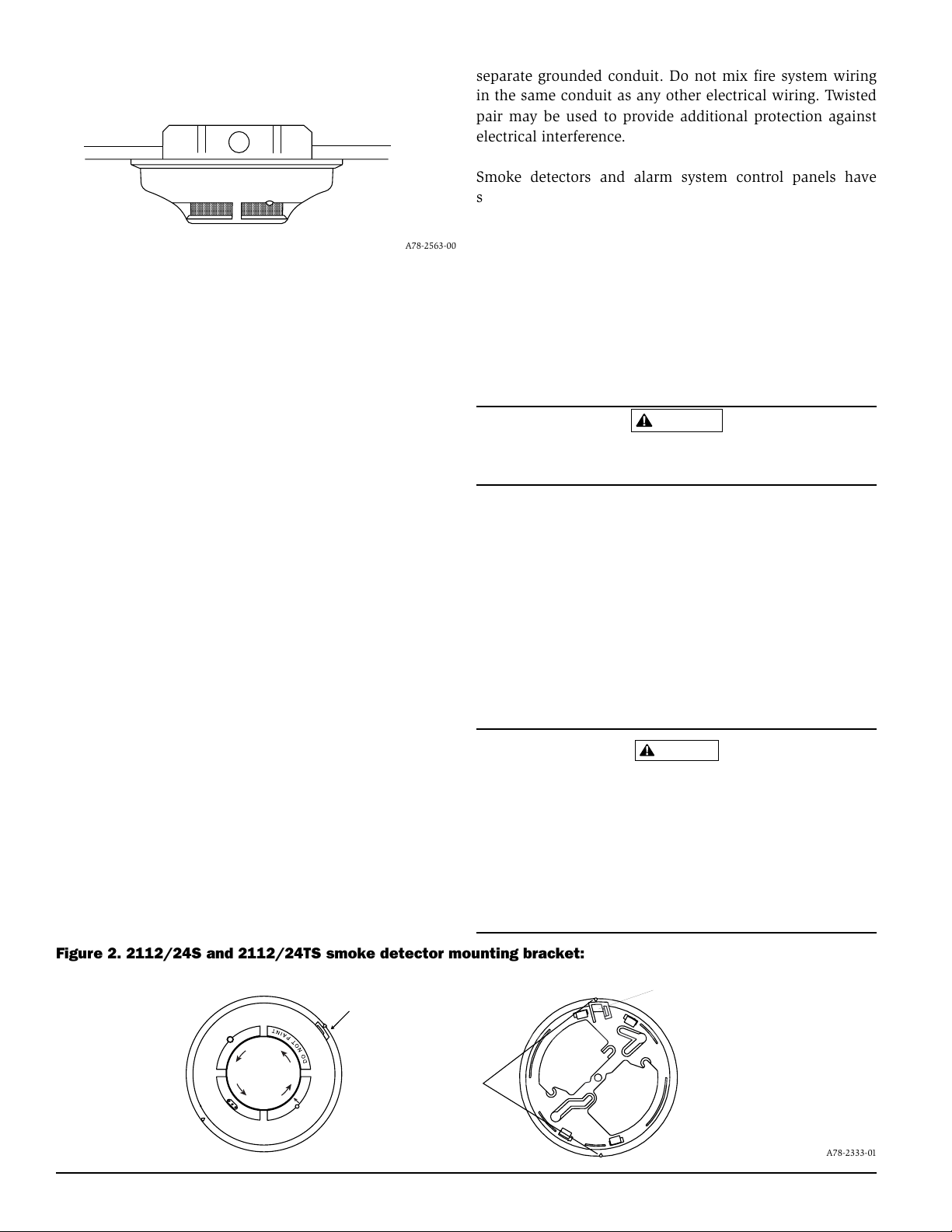
Figure 1. Surface mounting of 2112/24S smoke
;;;;;;;;;;;;;;;;;;;;;;;;
;;;;;;;;;;;;;;;;;;;;;;;;
;;;;;;;;;;;;;;;;;;;;;;;;
;;;;;;;;;;;;;;;;;;;;;;;;
;;;;;;;;;;;;;;;;;;;;;;;;
;;;;;;;;;;;;;;;;;;;;;;;;
;;;;;;;;;;;;;;;;;;;;;;;;
;;;;;;;;;;;;;;;;;;;;;;;;
;;;;;;;;;;;;;;;;;;;;;;;;
;;;;;;;;;;;;;;;;;;;;;;;;
;;;;;;;;;;;;;;;;;;;;;;;;
;;;;;;;;;;;;;;;;;;;;;;;;
detector on 31/2-inch and 4-inch octagonal box:
A78-2563-00
Mounting
Each 2112/24S and 2112/24TS detector is supplied with a
mounting bracket that permits the detector to be mounted:
1. To a single gang box, or
2. Directly to a 31/2-inch or 4-inch octagonal box, or
3. To a 4 inch square electrical box by using a plaster ring.
4. Directly to the ceiling using drywall anchors, if permitted by local codes and/or the authority having jurisdiction.
Tamper-resistant Feature
This detector includes a tamper-resistant feature that prevents its removal from the bracket without the use of a tool.
To make the detector tamper-resistant, remove the smaller
tab by breaking it at the scribed line on the tamper resistant
tab on the detector mounting bracket (see Figure 2), then
install the detector. To remove the detector from the bracket
once it has been made tamper resistant, use a small screwdriver to depress the tamper-resistant tab, located in the
slot on the mounting bracket, and turn the detector counterclockwise.
Wiring Installation Guidelines
All wiring must be installed in compliance with the National Electrical Code, applicable local codes, and any special requirements of the local authority having jurisdiction.
Proper wire gauges should be used. The conductors used to
connect smoke detectors to control panels and accessory
devices should be color-coded to reduce the likelihood of
wiring errors. Improper connections can prevent a system
from responding properly in the event of a fire.
The screw terminal block accepts 14 – 22 gauge wire. For
best system performance, all wiring should be installed in
separate grounded conduit. Do not mix fire system wiring
in the same conduit as any other electrical wiring. Twisted
pair may be used to provide additional protection against
electrical interference.
Smoke detectors and alarm system control panels have
specifications for allowable loop resistance. Consult the
control panel specifications for the total loop resistance allowed for the control panel being used before wiring the
detector loops.
Wire connections are made by stripping about 1/4 inch of
insulation from the end of the feed wire, inserting the wire
into the appropriate terminal, and tightening the screw to
secure the wire in place.
Installation
WARNING
Remove power from the control unit or initiating device circuits before installing detectors.
1. Wire the plug-in screw terminal block per Figure 3 and
plug the terminal block into the detector.
2. Align the arrows on the detector with the arrows on the
mounting bracket.
3. Turn the detector clockwise in the mounting bracket until it clicks into place.
4. After all detectors have been installed, apply power to
the control unit or initiating device circuits.
5. Test the detector as described in TESTING. (See page 3.)
6. Reset the detector at the system control panel.
7. Notify the proper authorities the system is in operation.
CAUTION
Dust covers are an effective way to limit the entry of dust
into smoke detector sensing chambers. However, they may
not completely prevent airborne dust particles from entering the detector. Therefore, System Sensor recommends the
removal of detectors before beginning construction or other
dust producing activity. Be sure to remove dust covers from
any sensors that were left in place during construction as
part of returning the system to service.
Figure 2. 2112/24S and 2112/24TS smoke detector mounting bracket:
TAMPER RESISTANT TAB
TAMPER SLOT
(DEPRESS TAB TO
REMOVE DETECTOR)
O
V
M
A
E
L
R
V
E
O
R
C
ALIGNMENT
C
R
O
E
V
R
L
E
A
M
V
O
ARROWS
D200-62-00 2 I56-932-12R
(CUT OFF SMALL TAB TO
ACTIVATE TAMPER-RESIST
FEATURE)
A78-2333-01
Page 3

Figure 3. Wiring diagram for the 2112/24S and 2112/24TS detector:
+
POWER
TO
DETECTORS
UL LISTED
CONTROL
PANEL
INITIATING
LOOP
–
+
P
+
W
–
N.O.
R
+
C
–
+
–
OPTIONAL CLASS A WIRING
NOTE
: Observe polarity in power and initiating loops when wiring.
+
+
N.O.
C
W
–
+
–
EOL POWER
SUPERVISION
RELAY (SHOWN
ENERGIZED)
A77-716 12/24V
P
R
EOL RESISTOR
SPECIFIED BY
PANEL
MANUFACTURER
A78-2336-03
Testing
NOTE: Before testing, notify the proper authorities that
the smoke detector system is undergoing maintenance and will be temporarily out of service. Disable the zone or system undergoing maintenance
to prevent unwanted alarms.
Detectors must be tested after installation and following
periodic maintenance. Test the 2112/24S as follows:
A. Test Switch
1. A recessed test switch is located on the detector housing (See Figure 4).
2. Press and hold the recessed test switch with a 0.18
inch maximum diameter tool such as an allen wrench
or small screwdriver.
3. The detector’s LED should light within 5 seconds.
B. Test Module (System Sensor Model No. MOD400R)
The MOD400R test module can be used with a DMM or
analog voltmeter to check the detector sensitivity as described in the test module’s manual.
C. Smoke Entry Test
Hold a smoldering punk stick or cotton wick at the side
of the detector and gently blow smoke through the detector until the unit alarms.
D. Direct Heat Method (Model 2112/24TS only – Hair dryer
of 1000-1500 watts)
Direct the heat toward either of the side thermistors.
Hold the heat source about 12 inches from the detector
in order to avoid damage to the plastic. The detector will
reset only after it has had sufficient time to cool and the
power source has been momentarily interrupted.
Both smoke and heat detection testing are recommended
for verifying system protection capability.
A detector that fails to activate with any of the above tests
should first be cleaned as outlined in MAINTENANCE. If
the detector still fails to activate, return it for repair.
Notify the proper authorities the system is back in
operation.
Maintenance
NOTE: Before removing the detector, notify the proper au-
thorities that the smoke detector system is undergoing maintenance and will be temporarily out of
service. Disable the zone or system undergoing
maintenance to prevent unwanted alarms.
Figure 4. Top and side views showing position of test switch:
LED
O
V
M
A
E
L
R
V
E
O
R
C
C
R
O
E
V
R
L
E
A
M
V
TEST MODULE
O
SOCKET
RECESSED TEST
SWITCH
D200-62-00 3 I56-932-12R
PUSH RECESSED
SWITCH WITH A
0.18″ MAX. DIAMETER TOOL
A78-2564-05
Page 4

of arrow.
;;;;;;;;;;;;;
;;;;;;;;;;;;;
;;;;;;;;;;;;;
;;;;;;;;;;;;;
;;;;;;;;;;;;;
;;;;;;;;;;;;;
;;;;;;;;;;;;;
yyyyyyyyyyyyy
yyyyyyyyyyyyy
yyyyyyyyyyyyy
yyyyyyyyyyyyy
yyyyyyyyyyyyy
yyyyyyyyyyyyy
yyyyyyyyyyyyy
;;;;;;;;;;;;;;
;;;;;;;;;;;;;;
;;;;;;;;;;;;;;
;;;;;;;;;;;;;;
;;;;;;;;;;;;;;
;;;;;;;;;;;;;;
;;;;;;;;;;;;;;
yyyyyyyyyyyyyy
yyyyyyyyyyyyyy
yyyyyyyyyyyyyy
yyyyyyyyyyyyyy
yyyyyyyyyyyyyy
yyyyyyyyyyyyyy
yyyyyyyyyyyyyy
;
;
;
;
;
;
;
y
y
y
y
y
y
y
2. Vacuum the cover carefully (See Figure 5).
3. Remove the sensing chamber cover.
4. Clean the sensing chamber by vacuuming or blow
ing out dust and particles.
5. Replace the sensing chamber cover, aligning the arrow on the
top of the chamber cover with the arrow on the housing.
6. Replace the cover by placing over the sensing chamber
cover and twisting until it snaps into place.
7. Reinstall the detector.
8. Notify the proper authorities that the system is back in
operation.
Figure 5. Removal of cover and screen for cleaning:1. Remove cover by turning counter clockwise in direction
REMOVABLE
SCREEN/COVER
(PART NO. C58-357-XX))
SENSING
CHAMBER COVER
HOUSING
A78-2565-07
Please refer to insert for the Limitations of Fire Alarm Systems
Three-Year Limited Warranty
System Sensor warrants its enclosed smoke detector to be free from defects in materials and workmanship under normal use and service for a
period of three years from date of manufacture. System Sensor makes no
other express warranty for this smoke detector. No agent, representative,
dealer, or employee of the Company has the authority to increase or alter
the obligations or limitations of this Warranty. The Company’s obligation
of this Warranty shall be limited to the repair or replacement of any part of
the smoke detector which is found to be defective in materials or workmanship under normal use and service during the three year period commencing with the date of manufacture. After phoning System Sensor’s toll
free number 800-SENSOR2 (736-7672) for a Return Authorization number,
send defective units postage prepaid to: System Sensor, Repair Depart-
D200-62-00 4 I56-932-12R
ment, RA #__________, 3825 Ohio Avenue, St. Charles, IL 60174. Please
include a note describing the malfunction and suspected cause of failure.
The Company shall not be obligated to repair or replace units which are
found to be defective because of damage, unreasonable use, modifications, or alterations occurring after the date of manufacture. In no case
shall the Company be liable for any consequential or incidental damages
for breach of this or any other Warranty, expressed or implied whatsoever,
even if the loss or damage is caused by the Company’s negligence or fault.
Some states do not allow the exclusion or limitation of incidental or consequential damages, so the above limitation or exclusion may not apply to
you. This Warranty gives you specific legal rights, and you may also have
other rights which vary from state to state.
©2001 System Sensor
 Loading...