

Page 1

CAUTION
Note
System Sensor™ Smoke
Sensor Model 2100ARFT
Document Number: 466-1747 Rev. C
September 2000
Product Summary
The System Sensor Smoke Sensor Model 2100ARFT
(smoke alarm) is a Learn Mode, wireless, photoelectric
smoke sensor with a self-contained alarm siren, a low-battery annunciator, and a status light. The smoke al arm is par t
of a security/fire alarm system and communicates with the
system control panel.
Each smoke alarm uses two 3-volt lithium batteries. The
batteries are shipped in the unit with a pull tab inserted at
the positive terminal. Remove the pull tab and reinstall the
batteries as needed, observing correct polarity.
The detector provides the following features:
❑ Fixed/rate of rise 135° F temperature heat detector
trips an alarm when the temperature reaches 135° F or
higher, or when the temperature rises rapidly.
❑ Freeze detector sends a trouble signal when the ambi-
ent temperature around the detector drops below 40° F.
This could indicate a heating problem on the premises.
System sirens sound trouble beeps, and if the condition
continues for one hour, the panel reports to central
monitoring station.
ITI Part No. 60-838-95, 60-838-95R
Installation Instructions
Not compatible with CareTaker®
versions with software versions 3.0 or earlier.
Not compatible with Commander® 2000 and custom
versions with software versions 4.0 or earlier.
Plus
and custom
Equipment Needed
❑ Phillips screwdriver.
❑ Pocket-sized slotted screwdriver.
Programming
This section describes the basic steps for adding the sensor
to panel memory. For more detailed programming information, refer to the specific panel installation instructions.
Note
Freeze detector only compatible with Concord™, Concord Express™, Ultragard®, and Advent® systems.
Simon® systems will only r es pond on site with troubl e
beeps and will not report the trouble condition to the
central monitoring station.
Installation Guidelines
❑ This equipment should be installed in accordance with
the National Fire Protection Association’s Standard 72
and/or Standard 74 (National Fire Protection Association, Batterymarch Park, Quincy, MA 02269).
❑ Avoid installing the unit until all construction is com-
pleted. The mounting ring may be pre-installed.
❑ Leave the orange dust cover on the unit until sheet
rocking and sanding are completed; otherwise, dust can
get into the unit and cause false alarms.
Note
The orange dust cover must be removed for the unit to
detect smoke.
Figure 1. Mounting Bracket
To add the smoke alarm to panel memory:
1. Put the panel in Program Mode/Learn Sensors.
2. Select a sensor group and sensor number.
3. Remove mounting bracket to trip tamper.
4. The panel will indicate that the sensor has been
learned.
5. Exit from program mode.
Reinstall smoke unit on mounting bracket. This
restores the tamper to normal—it may take the microprocessor in the smoke unit up to 12 seconds to
restore the tamper.
Mounting Guidelines
Selecting a suitable location is critical to the operation of
smoke alarms/detectors. This equipment should be installed
System Sensor™ Smoke Sensor Model 2100ARFT
1
Page 2
Mounting Guidelines
in accordance with the National Fire Protection Association’s (NFPA) Standard 72, Chapter 8.
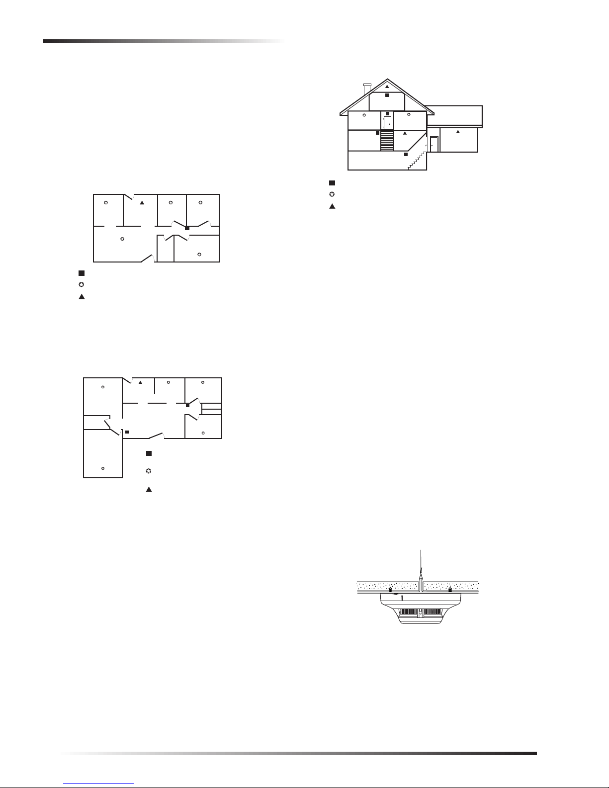
❑ NFPA 72, A-8-1.2.1.a Where to Locate the Required
Smoke Alarms/Detectors in Existing Construction. The
major threat from fire in a family living unit occurs at
night when everyone is as leep. The principal threat to
persons in sleeping areas comes from fires in the
remainder of the unit. Therefore, a smoke alarm(s)/
detector(s) is best located between the bedroom areas
and the rest of the unit. In units with only one bedroom
area on one floor, the smoke alarm(s)/detector(s)
should be located as shown in Figure 2.
BEDROOMBEDROOMKITCHENDINING
LIVING ROOM
SMOKE ALARMS/DETECTORS FOR MINIMUM PROTECTION
SMOKE ALARMS/DETECTORS FOR ADDITIONAL PROTECTION
HEAT ACTIVATED ALARMS/DETECTORS
Figure 2.Family units with one bedroom area.
BATH
BEDROOM
In family units with more than one bedroom area or
with bedrooms on more than one floor, more than one
smoke alarm/detector is required, as shown in
Figure 3.
KITCHEN
DINING ROOM
TV ROOM
BATHROOM
BEDROOM
Figure 3.Family units with more than one bedroom
area.
LIVING ROOM
SMOKE ALARMS/DETECTORS
FOR MINIMUM PROTECTION
SMOKE ALARMS/DETECTORS
FOR ADDITIONAL PROTECTION
HEAT ACTIVATED ALARMS/DETECTORS
BEDROOM
BEDROOM
BEDROOM
BASEMENT
BEDROOM
KITCHEN
GARAGE
BEDROOM
LIVING
ROOM
SMOKE ALARMS/DETECTORS FOR MINIMUM PROTECTION
SMOKE ALARMS/DETECTORS FOR ADDITIONAL PROTECTION
HEAT ACTIVATED ALARMS/DETECTORS
Figure 4.Multilevel residence.
NFPA 72, A-8-1.2.1.b Where to Locate the Required
Smoke Alarms/Detectors in New Construction. All of
the smoke alarms/detectors specified in A-8-1.2.1.a for
existing construction are required, and, in addition, a
smoke detector is required in each bedroom.
NFPA 72, A-8-1.2.1.c Are More Smoke Alarms/
Detectors Desirable? The required number of smoke
alarms/detectors might not provide reliable early
warning protection for those areas separated by a door
from the areas protected by the require d smoke a larms/
detectors. For this reason, it is recommended that the
householder consider the use of additional smoke
alarms/detectors for those areas for increased
protection. The additional areas include the basement,
bedrooms, dining room, furnace room, utility room,
and hallways not protected by the required smoke
alarms/detectors. The installation of smoke alarms/
detectors in kitchens, attics (finished or unfinished), or
garages is not normally recommended, as these
locations occasionally experience conditions that can
result in improper operation.
Important !
Regulations perta in in g to smo ke al ar m/d ete ctor in sta llations vary from state to state. For more information,
contact your local fire department or local authority
having jurisdiction.
In addition to smoke alarms/detectors outside of the
sleeping areas, Chapter 8 requires the installation of a
smoke alarm/detector on each additional story of the
family living unit, including the basement. These
installations are shown in Figure 4. The living area
smoke alarm/detector should be installed in the living
room or near the stairway to the upper leve l, or i n both
locations. The basement smoke alarm/detector should
be installed in close proximity to the stairway leading
to the floor above. Where installed on an open-joisted
ceiling, the alarm/detector should be positioned
relative to the stairway so as to intercept smoke
coming from a fire in the basement before smoke
enters the stairway.
2
❑ DO NOT mount a smoke alarm to a dr op ceiling tile;
mount it to a metal runner (see figure 5).
Figure 5.Smoke alarm mounted to drop ceiling.
❑ Mount all smoke alarms within 100 feet of the panel or
receiver.
❑ Install a minimum of two smoke alarms in any house-
hold, no matter how small it is.
❑ Put a smoke alarm in the hallway outside of every bed-
room area. A minimum of two smoke alarms are
required in homes with two bedroom areas.
System Sensor™ Smoke Sensor Model 2100ARFT
Page 3
Mounting
❑ Put a smoke alarm on every level of a multi-level resi-
dence.
❑ Install basement alarms on the ceiling at the bottom of
the basement stairwell.
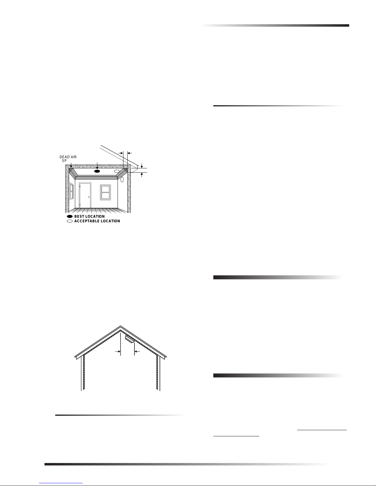
❑ Install smoke alarms on the ceiling as close to the cen-
ter of the room as possible. If this is not practical,
install it on the ceiling no closer than 4 inches (10 cm)
from any wall or corner (see figure 6).
❑ If ceiling mounting is not practical, install on an inside
wall between 4 and 6 inches (10 and 15 cm) from the
ceiling (see figure 6).
❑ Put smoke alarms at both ends of a bedroom hallw ay if
the hallway is more than 30 feet (9 meters) long. Large
rooms over 900 square feet require more than a single
sensor.
NO CLOSER THAN 4
DEAD AIR
SPACE
Figure 6.Smoke alarm mounting locations
BEST IN CENTER
OF CEILING
BEST LOCATION
ACCEPTABLE LOCATION
"
(10 cm)
FROM SIDE WALL
MOUNT ON WALL
AT LEAST 4
"
FROM CEILING
NO MORE
"
(15 cm)
THAN 6
FROM CEILING
(10 cm)
❑ Areas with rough ceilings or short, transom-type walls
coming down from the ceiling require additional smoke
alarms.
❑ Install second-floor smoke alarms on the ceiling at the
top of the first-to-second floor stairwell. Be sure no
door or other obstruction blocks the path of smoke to
the unit.
❑ In rooms with sloped, peaked, or gabled ceilings,
install smoke alarms 3 feet (0.9 meter) measured down
on the slant from the highest point of the ceiling (see
figure 7).
HORIZONTAL
DISTANCE
FROM PEAK
3 FEET
(.9M)
roofs, or smoke blocked by a closed door.
❑ Alarms may not detect smoke on other levels of the
building.
❑ Alarms may not warn in time when fires are caused by
smoking in bed, explosions, improper storage of flammables, overloaded electrical circuits, or other hazardous conditions.
Do Not Install Smoke Alarms in the
Following Locations:
❑ In or near areas where combustion particles are nor-
mally present such as kitchens; in garages where there
are particles of combustion in vehicle exhausts; near
furnaces, hot water heaters, or gas space heaters.
❑ On the ceiling in rooms next to kitchens where there is
no transom between the kitchen and these rooms.
❑ In damp or very humid areas, or next to bathrooms with
showers. Install sensors at least 5 feet (1.5 meters)
away from bathrooms.
❑ In very cold or very hot areas.
❑ In dusty, dirty, or insect-infested areas.
❑ Near fresh air inlets or returns or excessively drafty
areas. Air conditioners, heaters, fans, and fresh air
intakes and returns can drive smoke away from smoke
alarms.
❑ In dead air spaces at the top of a peaked ceil in g or wall /
ceiling intersect. Dead air may prevent smoke from
reaching a smoke alarm.
❑ Near fluorescent light fixtures. Install smoke alarms at
least 10 feet (3 meters) away from fluorescent light
fixtures.
Mounting
The mounting bracket must be separated from the unit
before you begin.
To mount the smoke alarm:
1. Secure the mounting bracket directly onto wood surfaces using No. 8, 1½ inch wood screws. If mounting
onto plaster or dry wall, use appropriate anchors.
2. Align the arrows on the mounting bracket with the
raised marks on the smoke alarm. Turn the smoke
alarm clockwise until it locks in place.
Figure 7.Sloped, peaked, or gabled ceilings
Limitations
All alarms are subject to possible compromise or failure-towarn for a variety of reasons, for example:
❑ Smoke alarms cannot det ect smoke i n chimne ys, w alls,
System Sensor™ Smoke Sensor Model 2100ARFT
Testing
Test each smoke alarm every week to verify that its siren
and signal integrity are ad equate. Refer to the s pecific pa nel
installation instructions for system response and sensor
testing.
To test the smoke alarm:
1. Put the panel in sensor test mode. Although not necessary for this model, it is a good practice to maintain.
Refer to the specific panel installation instructions for
details.
3
Page 4

Maintenance
Note
Simon and Advent panels respond to test button activations only when in sensor test mode.
!
WARNING
Commander and CareTaker panels will go into
alarm if not in sensor test when the test button is
pressed.
2. Press and hold the test button on the smoke alarm for 3
to 4 seconds.
Test Switch
Indicator Light
Pulsing: Normal/Thermal Alarm
Fast Blink: Smoke Alarm
None: Call for Service
Figure 8.Smoke Alarm Test Switch and Indicator Light.
A78-2332-03
The sensor should immediately transmit a test alarm signal,
causing the siren inside the smoke alarm to sound and the
status light to flash rapidly while the test button is pressed.
Refer to the specific panels installation instructions for
system response details.
Note
After verifying that the siren and signal integrity are
adequate, you may want to cover the center opening
with your thumb. This will help reduce the siren noise
until the test is completed.
Maintenance
Note
For UL installations, use the following battery brands:
Sanyo CR123A, Panasonic CR123A, or Duracell
DL123A. These can be obtained through Interactive
Technologies, Inc. Do not mix brands.
Cleaning
Clean the smoke alarm chamber at least once each year.
REMOVABLE
HOUSING
REMOVABLE
SCREEN
SENSING
CHAMBER COVER
SENSING
CHAMBER
BASE
Figure 9.Smoke Alarm diagram
To clean the smoke alarm chamber:
1. Place the panel in sensor test mode.
2. Remove smoke alarm from mounting ring.
3. Remove the batteries.
4. Separate housing from base.
5. Remove screen and chamber housing.
6. Vacuum screen, chamber housing, and chamber.
7. Reassemble smoke alarm.
8. Re-install the batteries.
9. Attach smoke alarm to mounting ring.
10. Test operation as describe in the “Testing” section.
Replacing Batteries
When the batteries need to be replaced, the unit transmits a
signal to the panel. If the batteries are not replaced within 7
days, the unit will chirp every 44 seconds until the unit
shuts down in 7-8 days.
Note
If you test the smoke alarm or it goes into alarm during this initial 7-day period, chirp delay is canceled.The unit will th e n b e gin chirping continuously at
44 second intervals until the unit shuts down in 7-8
days.
Constant exposure to high or low temperatures or high
humidity may reduce battery life. Replace both batteries
when the smoke alarm or panel notifies you that the
batteries are low.
4
Servicing
In the event that the smoke alarm needs servicing, send it to:
Interactive Technologies, Inc., 2266 Second St. North,
North St. Paul, MN 55109.
Emergencies
Develop plans for a variety of emergency situations.
Periodically discuss and rehearse emergency plans that
include the following:
❑ Know the normal state of doors and windows; open,
closed, or locked.
❑ Use a different escape route if closed doors feel hot to
the touch.
❑ Emphasize that everyone should escape as quickly as
possible. Do not stop to gather any belongings.
❑ Crawl and hold your breath as much as possible to help
reduce smoke inhalation during your escape.
System Sensor™ Smoke Sensor Model 2100ARFT
Page 5

Emergencies
N
❑ Meet at a designated outdoor location.
❑ Emphasize that no one should return to the premises if
there is a fire.
❑ Notify fire department from a neighbor’s phone.
!
WARNING
If you arrive at the premises and hear sirens, do
not attempt to enter the building. Call for emergency assistance from a neighbor’s phone.
Floor Plan Example
Figure 10 is an example of a multi le ve l f lo or plan. Use it as
a guide and draw your floor plan on the next page.
SMOKE ALARMS/DETECTORS FOR MINIMUM PROTECTION
SMOKE ALARMS/DETECTORS FOR ADDITIONAL PROTECTIO
HEAT ACTIVATED ALARMS/DETECTORS
A smoke detector should
be located on each level.
BEDROOM BEDROOM
BATH
BEDROOM
BASEMENT
BEDROOM BEDROOM
LIVING
ROOM
Smoke detectors should be located
between the sleeping area and the
rest of the family living unit.
RECREATION
ROOM
KITCHEN
BASEMENT
DINING
ROOM
ATTIC
LIVING
ROOM
BEDROOMBEDROOM
KITCHEN
LIVING
ROOM
Your Floor Plan
When establishing your escape routes, consider the
following guidelines:
❑ Show all building levels.
❑ Show all exits, (two exits per room are recommended).
❑ Show the location of all components of the fire system.
❑ Show the locations of any fire extinguishers, hoses,
ladders, etc.
TV
ROOM
BEDROOM
DINING
ROOM
LIVING
ROOM
KITCHEN
BEDROOM
BEDROOM
In family living units with more than
one sleeping area, locate a smoke
BATH
detector at each area.
Figure 10.Examples of a floor plans.
System Sensor™ Smoke Sensor Model 2100ARFT
5
Page 6

Emergencies
Draw you floor plan in this space.
6
System Sensor™ Smoke Sensor Model 2100ARFT
Page 7

Troubleshooting
Security
Automation
Fire Protection
Access Control
www.itii.com
T: 651/777-2690
F: 651/779-4890
I
nteractive Technologies, Inc.
2266 Second Street North
North Saint Paul, MN 55109-2900
1-800-777-1415
WIRELESS
Troubleshooting
The panel fails to indicate that the sensor has been
learned.
❑ Check panel programming. If necessary, reprogram the
sensor following the steps outlined in the Programming
section.
❑ Check sensor batteries.
The sensor fails to transmit an alarm signal when in test
mode.
❑ Check sensor batteries.
❑ Check panel programming. If necessary, reprogram the
sensor following the steps outlined in the Programming
section.
Specifications
Compatibility:
60-838-95 Advent, Commander 2000 and
Custom Versions with software
versions 4.1 and later, UltraGard and
Custom Versions, CareTaker Plus
and Custom Versions with software
versions 4.0 and later, Concord,
Concord Express, Simon, Quik
Bridge Loop Receivers, and Quik
Bridge® Repeater.
60-838-95R Concord, Concord Express, Simon,
Current: 12.5µA typical
Sensitivity Test: Use canned smoke SM-200 or
Dimensions: 2.0 × 5.0″ (without mounting
Temperature Range:
Operating 32° to 100°F (0° to 38°C)
Storage -4° to 140°F (-20° to 60°C)
Humidity: 90% non-condensing
Power Source: Two 3-volt lithium batteries of the
Sensitivity Levels:
Nominal: 1.00%/ft - 3.54%/ft obscuration
Nominal Supervisory: 2.25%/ft obscuration
Nominal Close to Alarm:
Nominal at Alarm: LED blinks once per second.
and Quik Bridge Loop Receivers.
28µA peak
54.8mA in alarm (average)
equivalent
bracket)
2.0 × 5.5″ (with mounting brac ket)
same type. UL-approved typ es:
Sanyo CR123A, Panasonic
CR123A, Duracell DL123A.
LED stops blinking at 44 sec.
intervals.
Notices
Agency Listings
UL 217—Residential Installations
UL 268—Commercial Installations
CUL—S531 - M87 Standard for Smoke Alarms
FCC Part 15 Information to the User
Changes or modifications not expressly approved by Interactive Technologies, Inc. can void the user’s authority to operate the equipment.
This device complies with part 15 of the FCC rules. Operation is subject to
the following two conditions:
❑ This device may not cause harmful interference.
❑ This device must accept any interference received, including interfer-
ence that may cause undesired operation.
Changes or modifications not expressly approved by Interactive Technologies, Inc. can void the user’s authority to operate the equipment.
FCC ID: B4Z-764A-SMOKE CANADIAN IC: 867-102-1644
Patent No.: 4,855,713 and 5,686,885 and 5,686,896 and 5,761,206
ITI Advent, CareTaker, Commander, UltraGard, Quik Bridge, and Simon
are registered trademarks of Interactive Technologies, Inc. Concord, Concord Express, and Learn Mode are trademarks of ITI. System Sensor is a
trademark of System Sensor.
System Sensor™ Smoke Sensor Model 2100ARFT
7
 Loading...