

Page 1
INSTALLATION AND MAINTENANCE INSTRUCTIONS
1012 Ionization and 2012 Photoelectronic
Smoke Detectors
Smoke Detector Description
Smoke detectors are designed to provide early warning of developing fires
at a reasonable cost. They monitor the air and can sense smoke and can
provide precious minutes for you and your family to escape before a fire
spreads. Early warning fire detection is best achieved by the installation of
fire detection equipment in all rooms and areas of the household.
Model 1012 is a low-voltage ionization-type smoke detector. Model 2012 is
a low-voltage photoelectronic-type smoke detector. The detector is designed for open area protection in a residential building. Each detector has
a built-in relay which may be used to activate auxiliary devices such as
bells, horns, and door closers. The relay contacts automatically close eight
(8) seconds after the detector goes into alarm, and automatically resets
approximately five (5) seconds after the alarm stops. In addition, these
detectors can be interconnected, within one household, for a system of up
to twelve (12) smoke detectors per household. This way, when one smoke
detector sounds its alarm horn, it will cause all of the other connected
smoke detectors within the household to sound their alarm horns as well.
Installation in Australia Only
The installation temperature range for Australia is 5° to 45°C and has
been tested per the Australian Standard. Ignore installation temperatures
specified for all other applications when installing detectors in Australia.
Detectors should be installed by qualified technicians. Installation of a
main connected power supply unit must be performed by qualified electricians only. Ignore the power requirements in "Smoke Detector Requirements" listed below, as these apply to installation in the USA.
The primary
power should be provided by a power limited, supervised, panel type system. A rechargeable battery is required as a backup to the external power
supply in case of a mains failure. In standby operation, the
power limited
backup battery (fully charged) must be capable of providing uninterrupted power for at least 7 days to the system and all smoke alarms before
the panel gives the required low-battery signal. When the low-battery signal is given, the battery should be capable of providing power for another
7 days, after which the backup battery should have enough energy left to
allow a 4-minute alarm signal to be given by all connected smoke alarms.
• Smoke detectors will not sense a fire if the smoke does not reach
the sensor. In order for a smoke detector to sense smoke, it must be
installed in the immediate vicinity of the fire. In addition, smoke from
fires in chimneys, in walls, on roofs, in remote parts of the building, or
on another level from where the smoke detector is located, may not
reach the smoke detector quickly enough for occupants to escape unharmed. For this reason, installer shall install smoke detectors on
every level, in every sleeping area, and in every bedroom of the
household.
• Smoke detectors may not be heard. The alarm horn in this smoke de-
tector meets or exceeds current Underwriter's Laboratories standards.
However, if the smoke detector is not located in the same room as the
occupant, or if it is blocked by a closed door or normal noise, the
alarm horn may not be heard. In addition, sound sleepers, or persons
who are under the influence of drugs or alcohol may not hear the
alarm or be able to react to it. Therefore, locate this smoke detector,
which has a sounder rated at 85 dB at 10 feet, on every level, in every sleeping area, and in every bedroom of the household.
• In general, detectors may not always warn you about fires caused by
carelessness and safety hazards like smoking in bed, violent explosions, escaping gas, improper storage of flammable materials, overloaded electrical circuits, children playing with matches, or arson.
• Smoke detectors are not fool-proof. Like all electronic devices, smoke
detectors have limitations. No type of smoke detector can sense every kind of fire every time. In addition, smoke from slow, smoldering fires rises slowly and may not reach the smoke detector until
actual flame breaks out. This type of smoke may not reach the
smoke detector in time for occupants to escape unharmed.
• Smoke detectors are not a substitute for life or property insurance.
Though smoke detectors have been responsible for saving many lives,
they are not warranted or implied to protect lives or property in the
event of a fire.
• Smoke detectors have a limited life. They contain many parts. Any of
these parts could fail at any time. Repair or replace the smoke detector
immediately if the alarm horn does not sound when tested. Do not, in
any case, use a smoke detector for more than 10 years from the date
of original installation.
A Division of Pittway
3825 Ohio Avenue, St. Charles, Illinois 60174
1-800-SENSOR2, FAX: 630-377-6495
Smoke Detector Power Requirements (USA)
This smoke detector will not work without power.
This smoke detector is
only U.L. listed to be powered by System Sensor Part No. A77-727-01 (12volt DC power supply). The A77-727-01 must be permanently connected
to the building's 120-volt AC electrical supply per code. The A77-727-01
will not power the smoke detector if the AC power is cut off for any rea-
Where to Install Smoke Detectors
Warning: As a minimum requirement, smoke detectors must be installed
in accordance with the National Fire Protection Agency (NFPA) Standard
72 which defines the standards for the National Fire Alarm Code (National
Fire Protection Association, Batterymarch Park, MA 02269-9101). In addi-
tion, observe all local and national building and electrical codes.
son. The 12-volt DC power supply will only power the detector when 120volt AC power is present—it is not a power back-up source.
Proper Detector Location:
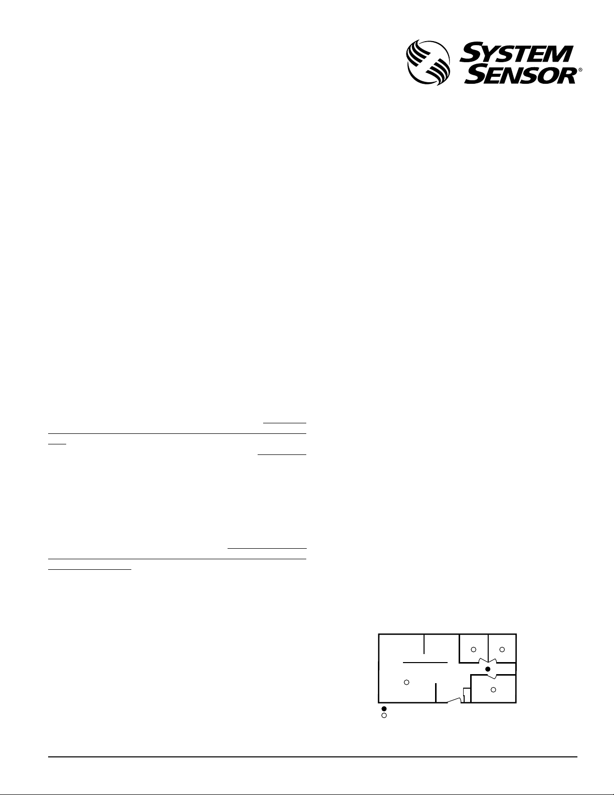
Figure 1: Recommended smoke detector protection for single-
Power input rating to the detector is 12VDC @ 0.02 amps. Input power to
the A77-727-01 power supply must be from a 24-hour 120V AC 60HZ circuit which cannot be turned off by a switch. Power supply and detector
floor residence with only one sleeping area
DINING ROOM KITCHEN BEDROOM BEDROOM
installation must conform to the electrical codes in your area and Article 760 of the National Electrical Code. It is recommended that wiring
be performed by a licensed electrician.
Smoke Detector Limitations
• This smoke detector is designed for residential use only. System
Sensor does not advise the use of this detector in multiple detector systems monitored by a central control. This detector is self-restoring and
SMOKE DETECTORS FOR MINIMUM PROTECTION
SMOKE DETECTORS FOR MORE PROTECTION AND
REQUIRED IN NEW CONSTRUCTION
BEDROOMLIVING ROOM
A78-1171-01
does not lock into an alarm condition.
D100-55-00 1 I56-733-10
Page 2
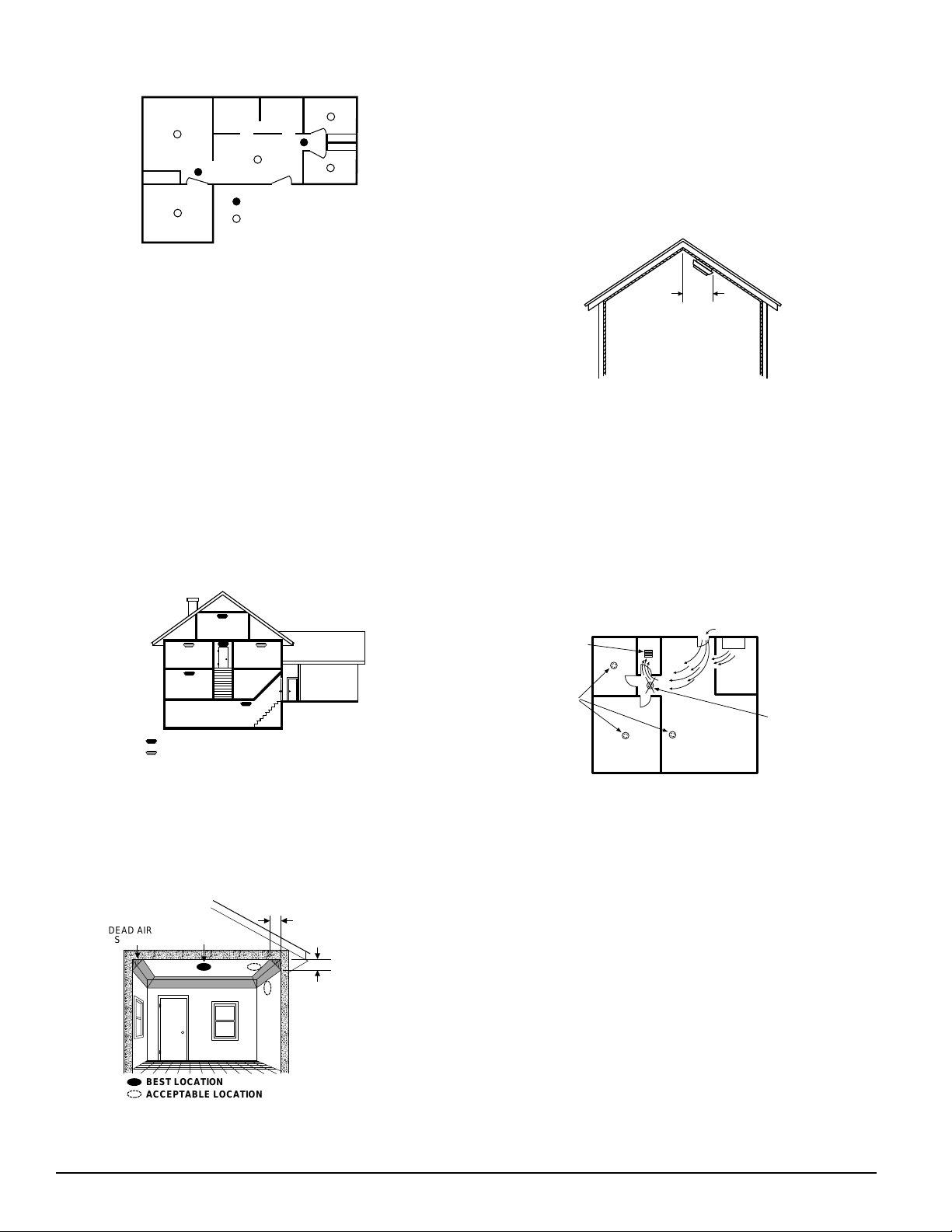
Figure 2: Recommended smoke detector protection for singlefloor residence with more than one sleeping area:
BEDROOM
KITCHENFAMILY ROOM
BEDROOM
DINING
ROOM
LIVING ROOM
BEDROOM
SMOKE DETECTORS FOR
MINIMUM PROTECTION
SMOKE DETECTORS FOR
MORE PROTECTION AND
REQUIRED IN NEW CONSTRUCTION
A78-1171-02
NFPA 72, Chapter 2, Section 2-2.1.1.1 states as follows: “Smoke detectors
shall be installed outside of each separate sleeping area in the immediate
vicinity of the bedrooms and on each additional story of the family living
• Rooms or areas that do not have smooth ceilings, or which have short,
transom-type walls coming down from the ceiling require additional
detectors.
• Install second-floor detectors on the ceiling at the top of the first-to-
second floor stairwell. Be sure no door or other obstruction blocks the
path of smoke to the detector.
• In rooms with sloped, peaked, or gabled ceilings, install detectors 3
feet (0.9 meter) measured down on the slant from the highest point of
the ceiling. See Figure 5.
Figure 5: Recommended smoke detector location in rooms with
sloped, gabled or peaked ceilings:
HORIZONTAL
DISTANCE
FROM PEAK
3 FEET
(.9M)
unit, including basements and excluding crawl spaces and unfinished attics. In new construction, a smoke detector also shall be installed in each
sleeping room.”
The above NFPA standard is a minimum requirement for smoke detector installation. For better protection, we also require the installation
of a smoke detector inside every bedroom in existing construction.
• Install a minimum of two smoke detectors in any household, no
matter how small it is.
• Put a smoke detector in the hallway outside of every separate bedroom area. (See Figure 1.) A minimum of two detectors are required in
homes with two bedroom areas. (See Figure 2.)
• Put a smoke detector on every level of a multi-level residence. (See
Figure 3.)
• Install basement detectors on the ceiling at the bottom of the basement
stairwell. (See Figure 3.)
Figure 3: Recommended smoke detector protection for a multilevel residence:
Where Smoke Detectors Should NOT Be Installed
• In or near areas where combustion particles are normally present
such as kitchens; in garages where there are particles of combustion
in vehicle exhausts; near furnaces, hot water heaters, or gas space
heaters. Install detectors at least 20 feet (6 meters) away from kitchens and other areas where combustion particles are normally
present.
• On the ceiling in rooms next to kitchens where there is no transom
between the kitchen and these rooms. Instead, install the smoke detector on an inside wall, furthest from the kitchen (See Figure 6). Be sure
not to install smoke detectors within 4" of the ceiling or any corner or
more than 6" from the ceiling.
A78-1171-05
Figure 6: Recommended smoke detector locations to avoid air
BEDROOM
BEDROOM BEDROOM
BASEMENT
KITCHEN
GARAGE
A78-1171-03
LIVING
ROOM
SMOKE DETECTORS FOR MINIMUM PROTECTION
SMOKE DETECTORS FOR MORE PROTECTION AND
REQUIRED IN NEW CONSTRUCTION
• Install detectors on the ceiling as close to the center of the room as
possible. If this is not practical, install it on the ceiling no closer than 4
inches (10 cm) from any wall or corner. (See Figure 4.)
• If wall-mounting is permitted by local and state codes, and ceiling
mounting is not practical, install detectors on an inside wall between 4
and 6 inches (10 and 15 cm) from the ceiling. (See Figure 4.)
Figure 4: Recommended smoke detector mounting locations:
DEAD AIR
SPACE
BEST IN CENTER
OF CEILING
NO CLOSER THAN 4
"
(10 cm)
FROM SIDE WALL
MOUNT ON WALL
AT LEAST 4
"
FROM CEILING
NO MORE
"
(15 cm)
THAN 6
FROM CEILING
(10 cm)
streams with combustion particles:
AIR RETURN
CORRECT
BEDROOM
BEDROOM
BATH
• In damp or very humid areas, or next to bathrooms with showers.
The moisture in humid air can enter the sensing chamber as water vapor, then cool and condense into droplets that cause a nuisance alarm.
Install detectors at least 5 feet (1.5 meters) away from bathrooms.
• In very cold or very hot rooms or areas. Operating temperature of the
smoke detector is 40°F to 100°F (4°C to 38°C).
• In dusty, dirty, or insect-infested areas. Dust and dirt can build up on
the detector’s sensing chamber and make it overly sensitive, or can
block openings to the sensing chamber and keep the detector from
sensing smoke.
• Near fresh air inlets or returns or excessively drafty areas. Air con-
ditioners, heaters, fans, and fresh air intakes and returns can drive
smoke away from smoke detectors, making the detectors less effective.
LIVING
ROOM
AIR INLET
STOVE
KITCHEN
INCORRECT
A78-1171-06
• In dead air spaces at the top of a peaked ceiling or wall/ceiling inter-
sect. Dead air may prevent smoke from reaching a detector.
• Near fluorescent light fixtures. Install detectors at least 10 feet (3
meters) away from such light fixtures.
BEST LOCATION
ACCEPTABLE LOCATION
A78-1171-04
• Put detectors at both ends of a bedroom hallway if the hallway is more
than 30 feet (9 meters) long. In addition, large rooms will require more
Installation Requirements
Warning: Electrical Shock Hazard. Turn off power at the main fuse box
or circuit breaker to the area of detector installation before beginning installation procedures.
• Mount detector to a 4-inch octagonal junction box only. Mount the 12
than a single detector if the room is over 900 square feet.
D100-55-00 2 I56-733-10
Page 3

Figure 7:
(+) (–)
POWER INPUT
GROUND
SIGNAL
(+) (–)
POWER INPUT
GROUND
SIGNAL
(+) (–)
POWER INPUT
GROUND
SIGNAL
RED
(+)
GRAY
(–)
POWERS UP TO
16 DETECTORS
A77-727-O1
12VDC POWER
SUPPLY
BLACK
BLACK
12OVAC
AUXILIARY
(+) (–)
POWER INPUT
AUXILIARY
8 UNITS
742
466
293
POWER INPUT
WIRE
GAUGE
14AWG
16AWG
18AWG
AUXILIARY
(+) (–)
AUXILIARY
1 UNIT
5000
3735
2349
GROUND
SIGNAL
2 UNITS
2970
1867
1174
POWER INPUT
INTERCONNECT UP TO
12 DETECTORS
3 UNITS
4 UNITS
1980
1485
1245
933
783
587
AUXILIARY
(+) (–)
AUXILIARY
5 UNITS
1188
747
469
GROUND
SIGNAL
6 UNITS
990
622
391
7 UNITS
848
533
335
Maximum power bus length in feet, given number of units (maximum per bus) and wire size.
Maximum interconnect bus length: 5,000 FT., No. 18AWG or larger dual conductor cable.
All wiring must conform to local electrical codes.
Relay contacts rating: 0.5A 30VDC; 0.5A 30VAC
Volt D.C. power supply to a 4" square junction box 2-1/8" deep only.
(If necessary, add an extension ring if the selected box does not have
adequate volume.) The power supply may be mounted remotely from
the detector.
• All wiring must be performed by a licensed electrician and installed in
compliance with the National Electrical Code, applicable local codes,
and any special requirements of the local authority having jurisdiction.
• Use only the specified wire gauge. Maximum interconnect bus length
is 5,000 feet, #18 AWG or larger two-conductor stranded cable.
• The detector includes a tamper-resist feature that, when activated, re-
quires a tool for detector removal. The following detector installation
instructions include how to activate this feature.
GROUND
SIGNAL
9 UNITS
660
415
261
Figure 8:
Dimensions
1-3/4" high
5-1/2" base dia.
10 UNITS
594
373
234
AUXILIARY
ALARM RELAY
11 UNITS
540
339
213
MOUNTING
BRACKET
MOUNTING
SCREW
REMOVE
12 UNITS
495
311
195
A78-2187-01
MOUNTING
SCREW
FOR TAMPER RESIST
BREAK OFF TAB HERE
ALIGNMENT
ARROW
Installation Instructions
1. Turn off power at main service panel.
2. Using wire connectors, attach either black wire from power supply to
black AC power wire. Attach other black wire from power supply to
INSTALL
WHEN INSTALLING:
ALIGN ARROWS ON MTG.
BRACKET 1" TO THE
RIGHT OF THE NIB ON
THE DETECTOR. ROTATE
UNTIL ARROW AND NIB
LINE UP.
A78-2012-00
white AC neutral wire.
3. Using wire connectors, connect red and gray power supply output
wires to the bus line wires supplying power to the remote detectors.
(See Figure 7.) Use color-coded bus wires.
4. Mount power supply to junction box and cover junction box with a 4"
square box cover, using box mounting screws.
5. Install a junction box where you plan to install the detector. (See type
and size for junction box above.)
6. Install bus line wires from power supply output to junction box. Use
#14-18 AWG wire only. See Figure 7 to determine maximum power bus
length for wire size and number of interconnected detectors.
7. Connect color-coded DC power bus wires to power input screw terminals, located on detector back. If detectors will be interconnected or the
relay used, see following sections for specific installation instructions.
8. Remove detector from mounting bracket by turning the detector
counter-clockwise and pulling the detector away from the bracket.
9. Remove small tab on mounting bracket to activate tamper-resist feature, if desired. (To release a detector with this feature, push up on
locking tab with screwdriver while turning detector counterclockwise.)
10. Install mounting bracket to junction box.
11. Connect power wires to detector(s) as shown in Figure 8. Be sure to
tighten each terminal screw to secure wire in place. Tug wire to be sure
it is connected properly.
12. Attach smoke detector to mounting bracket by aligning arrows on side
of mounting bracket 1-inch to the right of the nib on the detector. Rotate until the arrow and nib line up. (See Figure 8).
13. After installing all detectors, turn on power at the main service panel.
14. Check for the green LED to flash about once every 30 to 40 seconds.
This means the detector is receiving power. Check all detectors.
Note: If the LED does not flash, power is not getting to the smoke detec-
tor. Check wiring. If LED still does not flash, return the smoke detector to the manufacturer for repair.
15.Test each detector in the system. (See “Testing” below for more detailed instructions.)
D100-55-00 3 I56-733-10
Page 4

LED
Figure 9:
WARNING: Never use an open flame of any kind to test the smoke detector. You may set fire to and damage the detector, as well as your home.
The built-in test switch accurately tests all detector functions, as required
by Underwriter's Laboratories.
• DANGER: If the alarm horn sounds a loud continuous sound and
you are not testing the detector, the detector has sensed smoke or
combustion particles in the air. THE ALARM HORN IS A WARNING
OF A POSSIBLY SERIOUS SITUATION. IT REQUIRES YOUR IMMEDIATE ATTENTION. See “What to Do In Case of Fire” section of this
PUSH RECESSED SWITCH
WITH A 0.1" max. DIAMETER TOOL
RECESSED TEST
SWITCH
manual.
Connecting Auxiliary Devices with Relay
This detector has a built-in relay which may be used to activate auxiliary
devices such as bells, horns, and door closers. The relay contacts automatically close approximately eight (8) seconds after the detector goes
into alarm, and automatically resets approximately five (5) seconds after
the alarm stops. For wiring refer to Figure 8. Auxiliary voltage and current
requirements must be within relay contact ratings and appropriate wiring
must be used.
How to Interconnect Detectors
NOTE:Interconnect smoke detectors within one household only. If detec-
tors are interconnected between households, nuisance alarms will
occur when a detector in another residence is tested.
• Up to twelve 1012, 2012, and 2001LVRI detectors may be intercon-
nected so that if one detector senses smoke, all of them will sound an
alarm. After interconnecting the detectors, push the test switch on one
detector. The alarm horns on all of the other detectors should sound if
they are connected correctly.
• Connect the detectors together by connecting all the signal terminals
to each other and all ground terminals to each other. (See Figure 7.)
Use 18 guage (#18AWG) or larger two-conductor stranded wire.
• If detectors will not be interconnected, DO NOT use signal and
ground terminals.
• The LEDs on all smoke detectors should flash about 1 to 2 times per
minute when power is turned on to the detectors. Test detectors after
interconnection wiring is complete.
Cautionary Note: Test interconnection wiring after installation is com-
pleted. Test each unit in a system and make sure ALL other
units alarm. FAILURE TO OBSERVE ANY OF THESE CONDI-
TIONS CAN CAUSE SYSTEM MALFUNCTION AND/OR DAMAGE TO THE DETECTORS.
• The alarm could be caused by a nuisance situation. Cooking smoke or
a dusty furnace can cause the alarm to sound. If this happens, open a
window or fan the air to remove the smoke or dust. The alarm will
turn itself off as soon as the air is completely clear. DO NOT TURN
OFF POWER TO THE SMOKE DETECTOR. THIS WILL REMOVE
YOUR PROTECTION.
Monitoring Your Detector
Once the detector is powered, a green LED flashes about 1 to 2 times per
minute. This signals that the detector is receiving power and is in the detect mode. If the detector is not operating properly, the green LED will be
OFF. (If so, have the detector repaired or replaced immediately.) When the
smoke detector senses smoke, the green LED will flash rapidly. If the initiating smoke detector senses smoke and signals other interconnected
smoke detectors to sound their alarms, their LEDs will flash about 1 to 2
times per minute. See chart below for specific LED functions.
TABLE 1: DETECTOR STATUS
Detector Status Electronic Horn LED
Functioning Normally Silent Flashing about
Sounding Alarm; Beeping Continuously Flashing
Detecting Smoke (Steady Pulse) Rapidly
Sounding Alarm; Beeping Continuouslly 2012–Flashing about
Smoke Sensed by a (Steady Pulse) 1-2 times per minute
Connected Detector 1012–No flashing
1-2 times per minute
2001LVRI–No flashing
The detector will automatically return from Alarm to Normal state when
the reason for alarm, as the presence of smoke, is completely removed.
Cleaning and Maintenance
DANGER: Electrical Shock Hazard. Turn off power to the smoke detector
at the main service panel before cleaning the smoke detector.
Testing Information
• You should test your detector at least once a week to assure yourself of
its operation, as recommended by NFPA. Test the detector by firmly depressing the recessed test switch located on the detector cover (marked
“Push to Test”) with a 0.1 inch diameter tool such as an allen wrench
or small screwdriver FOR 20 SECONDS. (See Figure 9). The alarm
horn should sound, and the LED should flash rapidly.
• In an interconnected system, all of the detectors should sound their
alarm horns when any one of the test buttons is pushed. If the alarm
horn makes a continuous loud sound, the detector is working properly.
This is the only way to be sure the detector is working. Test the detector weekly. If the detector fails to test properly, have it repaired
or replaced immediately.
This smoke detector has been designed to be as maintenance-free as possible. However, regular testing (see “Testing” above) and periodic maintenance are necessary.
To clean the detector, turn off power and vacuum the outside of the detector with the soft brush attachment of a vacuum cleaner. Do this at least
once every year, preferably every six months. DO NOT ATTEMPT TO
CLEAN THE DETECTOR IN ANY OTHER WAY.
If the detector requires service, do not attempt to service it yourself; this
will void your warranty. Send the detector to: Repair Department, System
Sensor, 3825 Ohio Avenue, St. Charles, Illinois 60174. Enclose a note describing what is wrong with the detector.
Three-Year Limited Warranty
System Sensor warrants its enclosed smoke detector to be free from defects in materials and workmanship under normal use and service for a
period of three years from date of manufacture. System Sensor makes no
other express warranty for this smoke detector. No agent, representative,
dealer, or employee of the Company has the authority to increase or alter
the obligations or limitations of this Warranty. The Company’s obligation
of this Warranty shall be limited to the repair or replacement of any part of
the smoke detector which is found to be defective in materials or workmanship under normal use and service during the three year period commencing with the date of manufacture. After phoning System Sensor’s toll
free number 800-SENSOR2 (736-7672) for a Return Authorization number,
send defective units postage prepaid to: System Sensor, Repair Depart-
ment, RA #__________, 3825 Ohio Avenue, St. Charles, IL 60174. Please
include a note describing the malfunction and suspected cause of failure.
The Company shall not be obligated to repair or replace units which are
found to be defective because of damage, unreasonable use, modifications, or alterations occurring after the date of manufacture. In no case
shall the Company be liable for any consequential or incidental damages
for breach of this or any other Warranty, expressed or implied whatsoever,
even if the loss or damage is caused by the Company’s negligence or fault.
Some states do not allow the exclusion or limitation of incidental or consequential damages, so the above limitation or exclusion may not apply to
you. This Warranty gives you specific legal rights, and you may also have
other rights which vary from state to state.
D100-55-00 4 I56-733-10
© System Sensor 1996
 Loading...