

Page 1
z DANGER: If the alarm horn sounds a smoke-alarm and you are not
Figure 9 :
DINING ROOM KITCHEN BEDROOM BEDROOM
BEDROOMLIVING ROOM
SMOKE - ALARMS FOR MINIMUM PROTECTION
SMOKE - ALARMS FOR MORE PROTECTION AND
REQUIRED IN NEW CONSTRUCTION
PUSH TO SILENCE
PUSH AND HOLD TO TEST
Connecting Auxiliary Devices with Relay
This smoke-alarm has a built-in relay which may be used to activate auxiliary
devices such as bells, horns, and door closers. The relay contacts automatically
close approximately eight (8) seconds after the unit goes into alarm, and
automatically resets approximately five (5) seconds after the alarm stops. For
wiring refer to Figure 8. Auxiliary voltage and current requirements must be
within relay contact ratings and appropriate wiring must be used.
How to Interconnect Smoke-alarms
NOTE: Interconnect smoke-alarms within one residential unit only. If smoke-alarms
are interconnected between residential units, nuisance alarms will occur when
a smoke-alarm in another residence is tested. The model 2012/24AUS has
two interconnection modes which are shown in table 1.
TABLE 1: INTERCONNECTION MODES
Interconnection
Mode
SIGSND
SIGRLY
z Up to twelve 2012/24AUS smoke-alarms may be interconnected. The
2012/24AUS smoke-alarms may also be interconnected with 2012H
(A) when they all work at 12VDC supply voltage. If one smoke-alarm
senses smoke, all of the interconnected units will sound in SIGSND
mode, the relays of the interconnected units will be activated
approximately eight seconds after horns sound in SIGRLY mode. After
interconnecting the smoke-alarms, push and hold the test button for more
than 3 seconds on one unit. The alarm horns on all of the other smokealarms should sound if they are connected correctly.
z If any interconnected smoke-alarm is activated by another unit, it senses
smoke, the unit will go into local alarm state with the LED flashing
quickly.
z Connect the smoke-alarms together by interconnecting all the SIGSND
terminals to each other and all GND terminals to each other in SIGSND
mode, and interconnecting all the SIGRLY and GND terminals to each
other in SIGRLY mode (See Figure 7) . Use 0.75mm or larger two-conductor
standard wire.
z If smoke-alarms will not be connected. DO NOT use the SIGSND,
SIGRLY and GND terminals.
z The LEDs on all smoke-alarms should flash once about 40 seconds when
external power is turned on to the smoke-alarms. Test smoke-alarms after
interconnection wiring are complete.
Cautionary Note: Test interconnection wiring after installation is completed.
Testing Information
z You should test your smoke-alarm at least once a month to assure
yourself of its operation, as recommended by AS3786. Test the smokealarm by firmly depressing the test switch located on the smoke-alarm
cover (marked “Push and Hold to Test”) FOR 3 SECONDS. (See Figure
9). The alarm horn should sound, and the LED should flash rapidly.
When the test switch is pushed and held for more than 8 seconds, the
relay will be activated.
z In an interconnected system, all of the smoke-alarms should sound their
alarm horns when any one of the test buttons is pushed. The alarm horn
sounds if the smoke-alarm is working properly. This is the only way to
be sure the smoke-alarm is working. Test the smoke-alarm monthly.
If the smoke-alarm fails to test properly, have it repaired or replaced
immediately.
Interconnected
Test each unit in a system and make sure ALL other units alarm.
FAILURE TO OBSERVE ANY OF THESE CONDITIONS CAN
CAUSE SYSTEM MALFUNCTION AND/OR DAMAGE TO THE
SMOKE-ALARMS.
Terminals
SIGSND and
GND
SIGRLY and
GND
LED
Electronic
Horn
Sound
Sound
SILENCE/TEST SWITCH
Only the smoke-alarms
in local alarm are
activated
All the interconnected
smoke-alarms are
activated
Relay
Please refer to insert for the Limitations of fire alarm systems
4 I56-2012-00C
testing the unit, the smoke-alarm has sensed smoke or combustion
particles in the air. THE ALARM HORN IS A WARNING OF A
POSSIBLY SERIOUS SITUATION. IT REQUIRES YOUR
IMMEDIATE ATTENTION.
z The alarm could be caused by a nuisance situation. Cooking smoke or a
dusty furnace can cause the smoke-alarm to sound. If this happens, open
a window or fan the air to remove the smoke or dust. The smoke-alarm
will turn itself off as soon as the air is completely clear.
DO NOT OFF POWER TO THE SMOKE-ALARM. THIS WILL
REMOVE YOUR PROTECTION.
Monitoring Your Smoke-alarm
Once the smoke-alarm is energized from an external power, a green LED flashes once
about 40 seconds. This signals that the smoke-alarm is receiving power and is in the
detection mode. If the smoke-alarm is not operating properly, the green LED will be OFF.
(If so, have the smoke-alarm repaired or replaced immediately.) When the
smoke-alarm senses smoke, the green LED will flash rapidly. If the initiating
smoke-alarm senses smoke and signals other interconnected smoke-alarms to
sound their alarm horns, their LEDs will stop flashing. See TABLE 2 for specific
LED functions.
TABLE 2: SMOKE-ALARM STATUS
Smoke-alarm
Status
Normal Standby Silent
Silence State
Local Alarm Temporal Tone Flash rapidly
SIGSND Signal
Received
SIGRLY Signal
Received
Failed chamber
test
Low battery
voltage
The smoke-alarm will automatically return from Alarm to Normal state when the
reason for alarm, as the presence of smoke, is completely removed.
Cleaning and Maintenance
DANGER: Electrical Shock Hazard. Turn off power to the smoke-alarm at the
main service panel before cleaning the smoke-alarm.
This smoke-alarm has been designed to be as maintenance-free as possible.
However, regular testing (see “Testing” above) and periodic maintenance are
necessary.
To clean the smoke-alarm, turn off power and vacuum the outside of the smokealarm with the soft brush attachment of a vacuum cleaner. Do this at least once
every year, preferably every six months. DO NOT ATTEMPT TO CLEAN
THE SMOKE-ALARM IN ANY OTHER WAY.
If the smoke-alarm requires service, do not attempt to service it yourself; this will
void your warranty. Return the smoke-alarm to your local System Sensor distributor
or agent. Enclose a note describing what is wrong with the smoke-alarm.
Special Note Regarding Smoke-alarm Guards
Smoke-alarms are not to be used with alarm guards unless the combination has
been evaluated and found suitable for that purpose.
www.systemsensor.com
Electronic Horn LED
Flash every 40
Beep every 40
seconds(synchronized
with the LED On)
Temporal Tone Off
Temporal Tone Off
Beep every 40
seconds(synchronized
with the LED On)
Beep every 40
seconds(At the middle
of the two LED On
time)
seconds
Flash every 40
seconds
Flash every 10
seconds
Flash every 40
seconds
Relay
Open
Open
Closed after
8 seconds
Open
Closed after
8 seconds
Open
Open
Ver. A
INSTALLATION AND MAINTENANCE INSTRUCTIONS
2012/24AUS Photoelectric Smoke-Alarm
with Integral Temp-3 Sounder
Specifications
Supply V oltage Range:
Max. Standby Current:
Max. Alarm Current:
P-Horn Sound Output Level:
Max. Interconnected Units:
Silence Mode Timeout Period:
Silence Mode Indication:
Height:
Diameter:
Weight:
Operating Temperature Range:
Humidity:
General Description
Smoke-alarms are designed to provide early warning of developing fires at a
reasonable cost. They monitor the air and can sense smoke, providing precious
minutes for you and your family to escape before a fire spreads. Early warning
fire detection is best achieved by the installation of fire detection equipment in
all rooms and areas of the household.
Model 2012/24AUS is a photoelectric smoke-alarm designed for open area
protection in a residential building. It has a built-in relay which may be used to
activate auxiliary devices such as bells, horns, and door closers. The relay
contacts automatically close 8 seconds after the smoke-alarm goes into alarm,
and automatically resets approximately 5 seconds after the alarm stops. A
piezoelectric horn in each smoke-alarm produces an audible 85dB(A) temporal
tone evacuation signal when a unit alarms or an interconnected one alarms. This
temporal tone evacuation signal complies with AS 3786. The signal consists of 3
beeps each 0.5 seconds long, spaced 0.5 seconds apart, followed by 1.5 seconds
of silence. The horn will beep every 40 seconds as the battery voltage is lower
than 8.5V. These smoke-alarms can be interconnected with the SIGSND
and GND terminals for a system of up to 24 smoke-alarms per premises so when
one smoke-alarm sounds its evacuation signal it causes the other connected
smoke-alarms to sound as well. They also can be interconnected with the
SIGRLY and GND terminals, when any one alarms, all the interconnected units’
relays will be activated approximately 8 seconds after horns sound. Model
2012/24AUS has a backup battery in case of main power failures. The smokealarm has a built-in silence/test push button to silence or test. If the silence/test
button is pushed for less than 3 seconds, this is a silence instruction, the smokealarm will reduce its sensitivity and give an audible trouble signal for 8
minutes. If the silence/test button is pushed and held for more than 3 seconds,
this is a test instruction and will also cancel the silence mode (See “Testing” below
for more detailed instructions.)
Smoke-Alarm Power Requirements
Power input rating to the smoke-alarm is 12/24VDC@0.05 Amp. Power supply
and smoke-alarm installation must conform to the electrical codes in your area. It
is recommended that wiring be performed by a licensed electrician.
Installation in Australia
The installation temperature range for Australia is 0°C to 50°C and has been tested
per the Australian Standard. Smoke-alarms should be installed by qualified
technicians. Installation of a main connected power supply unit must be performed
by qualified electricians only.
Smoke-alarm Limitations
z This smoke-alarm is designed for residential use only. This smoke-alarm is
self-restoring and does not lock into an alarm condition.
z Smoke-alarms will not sense a fire if the smoke does not reach the sensor.
In order for a smoke-alarm to sense smoke, it must be installed in the
immediate vicinity of the fire. In addition, smoke from fires in chimneys, in
walls, on roofs, in remote parts of the building, or on another level from
where the smoke-alarm is located, may not reach the smoke-alarm quickly
enough for occupants to escape unharmed. For this reason, the installer
shall install smoke-alarms on every level, in every sleeping area, and in
every bedroom of the household.
1 I56-2012-00C
10VDC~30VDC
60µA
50mA
85dB(A) at 3m
24
8 minutes or cancel by pressing silence/test button for more than 3 seconds
Sounder Beeps and LED Flashes Green once every 40 secs.
55mm
135mm
220g
0 to 5℃ 0℃
5% to 93% R.H.
z Smoke-alarms may not be heard. The alarm horn in this smoke-alarm
meets or exceeds current Australian standards. However, if the smokealarm is not located in the same room as the occupant, or if it is blocked by
a closed door or normal noise, the alarm horn may not be heard. In
addition, sound sleepers, or persons who are under the influence of drugs
or alcohol may not hear the alarm or be able to react to it. Therefore, locate
this smoke-alarm, which has a sounder rated at 85dB(A) at 3 meters, on
every level, in every sleeping area, and in every bedroom of the household.
z In general, smoke-alarms may not always warn you about fires caused by
carelessness and safety hazards like smoking in bed, violent explosions,
escaping gas, improper storage of flammable materials, overloaded
electrical circuits, children playing with matches, or arson.
z Smoke-alarms are not fool-proof. Like all electronic devices, smoke-
alarms have limitations. No type of smoke-alarm can sense every kind of
fire every time. In addition, smoke from slow , smoldering fires rises
slowly and may not reach the smoke-alarm until actual flame breaks out.
This type of smoke may not reach the smoke-alarm in time for occupants
to escape unharmed.
Smoke-alarms are not a substitute for life or property insurance. Though
smoke-alarms have been responsible for saving many lives, they are not
warranted or implied to protect lives or property in the event of a fire.
z A preventative maintenance agreement should be arranged through the
local manufacturer’s representative. Though smoke-alarms are designed
for long life, they may fail at any time. Therefore, smoke-alarms shall be
replaced after being in service for 10 years. Any smoke-alarm, fire alarm
equipment, or any component of that system which fails shall be repaired
or replaced as soon as possible.
Where to Install Smoke-alarms
Warning: As a minimum requirement, smoke-alarms must be installed in
accordance with the requirements of AS3000, AS3786 and AS1670.1-2004.
Proper Smoke-alarm Location:
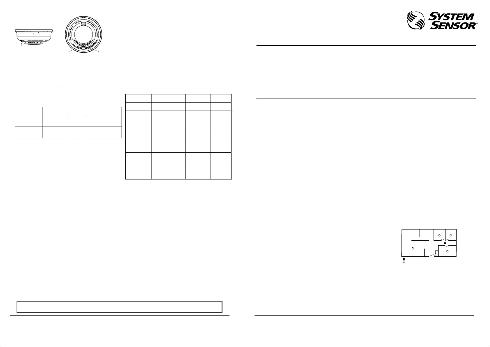
Figure 1: Recommended smoke-alarm protection for single-floor residence with
only one sleeping area:
28 Tuan Jie South Road, Xi’an National
Hi-tech Industrial Development Zone
Province of Shaanxi, 710075, China
Page 2
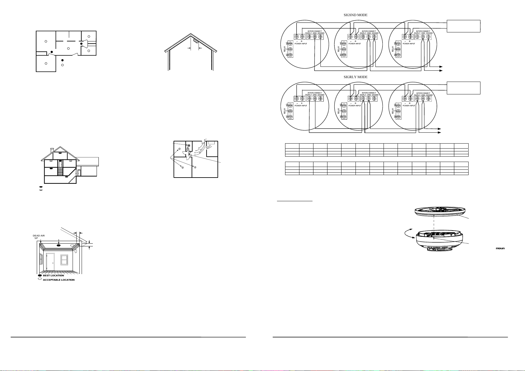
Figure 2: Recommended smoke-alarm protection for single-floor residence
BEDROOM
SMOKE - ALARMS FOR
MINIMUM PROTECTION
SMOKE - ALARMS FOR
MORE PROTECTION AND
REQUIRED IN NEW CONSTRUCTION
BEDROOM
BEDROOM
LIVING ROOM
DINING
ROOM
KITCHENFAMILY ROOM
BEDROOM
BEDROOM BEDROOM
LIVING
ROOM
KITCHEN
BASEMENT
GARAGE
SMOKE - ALARMS FOR MINIMUM PROTECTION
SMOKE - ALARMS FOR MORE PROTECTION AND
REQUIRED IN NEW CONSTRUCTION
BEST LOCATION
ACCEPTABLE LOCATION
DEAD AIR
SPACE
BEST IN CENTER
OF CEILING
NO CLOSER THAN 4" (10 cm)
FROM SIDE WALL
MOUNT ON WALL
AT LEAST 4" (10 cm)
FROM CEILING
NO MORE
THAN 6" (15 cm)
FROM CEILING
HORIZONTAL
DISTANCE
FROM PEAK
3 FEET
(.9M)
CORRECT
AIR RETURN
BEDROOM
BATH
BEDROOM
LIVING
ROOM
INCORRECT
KITCHEN
STOVE
AIR INLET
with more than one sleeping area:
Smoke-alarms shall be installed outside of each separate sleeping area in the
immediate vicinity of the bedrooms and on each additional story of the family
living unit, including basements and excluding crawl spaces and unfinished
attics. In new construction, a smoke-alarm also shall be installed in each sleeping
room.”
For better protection, we also require the installation of a smoke-alarm inside
every bedroom in existing construction.
z Install a minimum of two smoke-alarms in any household, no matter how
small it is.
Put a smoke-alarm in the hallway outside of every separate bedroom area.
(See Figure 1.) A minimum of two smoke-alarms are required in homes
with two bedroom areas. (See Figure 2.)
Put a smoke-alarm on every level of a multi-level residence.(SeeFigure
z
z Install basement smoke-alarms on the ceiling at the bottom of the
basement stairwell. (See Figure 3.)
Figure 3: Recommended smoke-alarm protection for a multi-level
z Install smoke-alarms on the ceiling as close to the center of the room as
possible. If this is not practical, install it on the ceiling no closer than 4
inches (10 cm) from any wall or corner. (See Figure 4.)
z If wall-mounting is permitted by local and state codes, and ceiling
mounting is not practical, install smoke-alarms on an inside wall between
4 and 6 inches (10 and 15 cm) from the ceiling. (See Figure 4.)
Figure 4: Recommended smoke-alarm mounting locations:
z Put smoke-alarms at both ends of a bedroom hallway if the hallway is
morethan 30 feet (9 meters) long. In addition, large rooms will require
more than a single smoke-alarm if the room is over 900 square feet.
z Rooms or areas that do not have smooth ceilings, or which have short,
transom-type walls coming down from the ceiling require additional
smoke-alarms.
z Install second-floor smoke-alarms on the ceiling at the top of the first-to-
second floor stairwell. Be sure no door or other obstruction blocks the path
of smoke to the smoke-alarm.
In rooms with sloped, peaked, or gabled ceilings, install smoke-alarms 3 feet (0.9
meter) measured down on the slant from the highest point of the ceiling. See
Figure 5
2 I56-2012-00C
3.)
residence:
Figure 5: Recommended smoke-alarm location in rooms with sloped, gabled
or peaked ceilings:
Where Smoke-alarms Should NOT Be Installed
z In or near areas where combustion particles are normally present such as
kitchens; in garages where there are particles of combustion in vehicle
exhausts; near furnaces, hot water heaters, or gas space heaters. Install
smoke-alarms at least 20 feet (6 meters)away from kitchens and other
areas where combustion particles are normally present.
z On the ceiling in rooms next to kitchens where there is no transom
between the kitchen and these rooms. Instead, install the smoke-alarm
inside wall, furthest from the kitchen (See Figure 6). Be sure not to
install smoke-alarms within 4" of the ceiling or any corner or more than
6" from the ceiling.
Figure 6: Recommended smoke-alarm locations to avoid air streams with
combustion particles:
z In damp or very humid areas, or next to bathrooms with showers. The
moisture in humid air can enter the sensing chamber as water vapor, then
cool and condense into droplets that cause a nuisance alarm. Install smokealarms at least 5 feet (1.5 meters) away from bath-rooms.
z In very cold or very hot rooms or areas. Operating temperature of the
smoke-alarm is -10°C to 55°C.
z In dusty, dirty, or insect-infested areas. Dust and dirt can build up on the
smoke-alarm’s sensing chamber and make it overly sensitive, or can block
openings to the sensing chamber and keep the smoke-alarm from sensing
smoke.
z Near fresh air inlets or returns or excessively drafty areas. Air
conditioners, heaters, fans, and fresh air intakes and returns can drive
smoke away from smoke-alarms, making the units less effective.
z In dead air spaces at the top of a peaked ceiling or wall/ceiling intersect.
Dead air may prevent smoke from reaching a smoke-alarm.
z Near fluorescent light fixtures. Install smoke-alarms at least 10 feet (3
meters) away from such light fixtures.
Installation Requirements
Warning: Electrical Shock Hazard. Turn off power at the main fuse box or circuit
breaker to the area of smoke-alarm installation before beginning installation
procedures.
z Mount smoke-alarm to a 4-inch octagonal junction box only. Mount the
12/24 Volt D.C. power supply to a 4" square junction box 2-1/8" deep
only. (If necessary, add an extension ring if the selected box does not have
adequate volume.) The power supply may be mounted remotely from the
smoke-alarm.
z All wiring must be performed by a licensed electrician.
z Use only the specified wire gauge.
z The smoke-alarm includes a tamper-resist feature that, when activated,
requires a tool for smoke-alarm removal. The following smoke-alarm
installation instructions include how to activate this feature.
Figure 7:
(-)
12/24VDC SUPPLY
(+)
12/24VDC SUPPLY
INTERCONNECT UP TO 24 SMOKE-ALARMS
(-)
12/24VDC SUPPLY
(+)
on an
Maximum power bus length in meters, given number of units (maximum per bus) and wire size (mm
Supply Voltage = 12VDC
WI RE SIZE
1 UNIT 2 UNITS 3 UNITS 4 UNITS 5 UNITS 6 UNITS 7 UNITS 8 UNITS 9 UNIT S 10 UNITS 11 UNITS 12 UNITS
2
)
( mm
1.5 3302 1652 1101 826 660 551 471 413 366 331 301 275
1.0 1633 817 544 408 327 273 233 205 182 163 149 135
0.75 819 411 273 205 163 138 117 103 91 82 75 68
WIRE SIZE
13 UNITS 14 UNITS 15 UNITS 16 UNITS 17 UNITS 18 UNITS 19 UNITS 20 UNITS 21 UNIT S 22 UNITS 23 UNITS 24 UNITS
2
)
( mm
1.5 254 236 220 206 194 183 174 165 157 150 144 138
1.0 126 117 109 102 96 91 86 82 78 74 71 68
0.75 63 59 55 51 48 46 43 41 39 37 36 34
For 24VDC supply voltage, the maximum power bus length is 4 times as long as 12VDC supply voltage.
Maximum interconnect bus length: 2000 meters, 0.75mm
All wiring must conform to local electrical codes.
Installation Instructions
1. Turn off power at main service panel.
2. Using wire connectors, connect power supply output wires to the bus line
wires supplying power to the remote smoke-alarms. (See Figure 7.) Use
color-coded bus wires.
3. Mount power supply to junction box and cover junction box with a 4"
square box cover, using box mounting screws.
4. Install a junction box where you plan to install the smoke-alarm. (See type
and size for junction box above.)
5. Install bus line wires from power supply output to junction box. Use 0.75
to1.5mm wire only. See Figure 7 to determine maximum power bus length for
wire size and number of interconnected smoke-alarms.
6. Connect color-coded DC power bus wires to power input screw terminals,
located on smoke-alarm back. If smoke-alarms will be interconnected or the
relay used, see following sections for specific installation instructions.
7. Remove smoke-alarm from mounting bracket by turning the smoke-alarm
counter-clockwise and pulling the smoke-alarm away from the bracket.
8. Remove small tab on mounting bracket to activate tamper-resist feature, if
desired. (To release a smoke-alarm with this feature, push up on locking tab
with screwdriver while turning smoke-alarm counterclockwise.)
9. Install mounting bracket to junction box.
10. Connect power wires to the smoke-alarm(s) as shown in Figure 8. Be sure
to tighten each terminal screw to secure wire in place. Tug wire to be sure it
is connected properly.
11. Battery installation instruction˖
Please open the cover of the battery box on the base with a screwdriver ;
Then take the battery button out of the box carefully;
Fasten the battery into the button.
Insert the battery into the box, lock the battery cover with a screwdriver.
NOTE:
z Only the allowed battery model can be used.
z Recommended periodic battery replacement interval: 18 months.
3 I56-2012-00C
SIGRLY MODE
2
or larger cable.
12/24VDC SUPPLY
INTERCONNECT UP TO 24 SMOKE-ALARMS
2
Figure 8:
Remove
Install
z The battery box cover will be held up by the spring slice and can not
be closed if the battery is not installed.
z Replacement 9VDC batteries can be purchased from the following
retail outlets throughout Australia & New Zealand:
Bunnings, Mitre 10, Tandy and Dick Smith.
12. Attach the smoke-alarm to mounting bracket by aligning arrows on side of
mounting bracket 1-inch to the right of the nib on the smoke-alarm. Rotate
until the arrow and nib line up. (See Figure 8).
13. After installing all smoke-alarms, turn on power at the main service panel.
14. Check for the green LED to flash once about 40 seconds. This means the
smoke-alarm is receiving power. Check all smoke-alarms.
Note: If the LED does not flash, power is not getting to the smoke-alarm.
Check wiring. If LED still does not flash, return the smoke-alarmto the
manufacturer for repair.
Test each smoke-alarm in the system. (See “Testing” below for more
detailed instructions.)
).
Mounting Bracket
When Installing:
Align arrows on mounting
bracket 1" to the right of
the nib on the smoke alarm.
Rotate until arrow and
nib line up.
 Loading...