

Page 1

INSTALLATION AND MAINTENANCE INSTRUCTIONS
1551B Plug-in Intelligent
3825 Ohio Avenue, St. Charles, Illinois 60174
Ionization Sensors with Communications
Specifications
Diameter: 6.1 inches (155 mm) installed in B501B
4.1 inches (104 mm) installed in B501
Height: 2.3 inches (58 mm)
Weight: 5 ounces (150 gm)
Operating Temperature Range: -10° to 60°C (14° to 140°F)
Note: Do not install where normal ambient temperatures extend beyond 0° to 49°C
(32° to 120°F)
Operating Humidity Range: 10% to 93% Relative Humidity
Mounting: B501B flanged base
B501 flangeless base
B501 with RMK400 recessed mounting kit
B501BH Base with horn
Maximum Air Velocity: 1500 Ft./Min. (7.6 m/S)
Voltage Range: 15 to 32 VDC
Standby Current: 200 µA maximum @ 24 VDC (with no communication)
300 µA average maximum @ 24 VDC (with one communication every five seconds
and LED blink enabled)
LED Current: 6.5 mA @ 24 VDC
A Division of Pittway
1-800-SENSOR2, FAX: 630-377-6495
Before Installing
Please thoroughly read Guide for Proper Use of System
Smoke Detectors (I56-407-XX), which provides detailed in-
formation on sensor spacing, placement, zoning, and special applications. Copies of this manual are available from
System Sensor.
General Description
Models 1551B dual-chamber ionization intelligent sensors
utilize a state-of-the-art, unipolar sensing chamber. These
sensors are designed for use with duct housings DH500
and DH500AC/DC only, and to be used with compatible
control panels only. Connect sensors only to compatible
control units. (For installation in Canada, refer to CAN/
ULC-S524-M86, Standard for the Installation of Fire Alarm
Systems and CEC Part 1, Sec. 32.)
Tw o LED’s on each sensor light to pr ovide a local 360° visibility of the sensor indication. The LED’s can be latched
on by code command from the panel for an alarm indication. The LED’s can also be unlatched to the normal condition by code command. Remote LED annunciator
capability is available as an optional accessory (Part No.
RA400).
Wiring Guide
Model 155 1B can be used with an y one of a variety of plugin bases. Therefore, connect all wiring following the
installation instructions provided with the base that was
selected for use with the 1551B. As Figure 1 indicates,
bases are equipped with screw terminals for all
appropriate connections.
NOTE: All wiring must conform to applicable local codes,
ordinances, and regulations.
NOTE: Verify that all sensor bases are installed and that
the wiring polarity is correct at each base.
WARNING
Remove power from the loop before installing sensors.
1. Install sensors:
a. Verify that the sensor type matches the type written
on the label on the base.
b. Set the sensor to the desired address and record it on
the label on the base.
c. Place the sensor into the sensor base.
d. Rotate the sensor clockwise until it drops into place.
e. Continue rotating the sensor clockwise until it locks
in place.
D500-40-00 1 I56-1436-00
Page 2
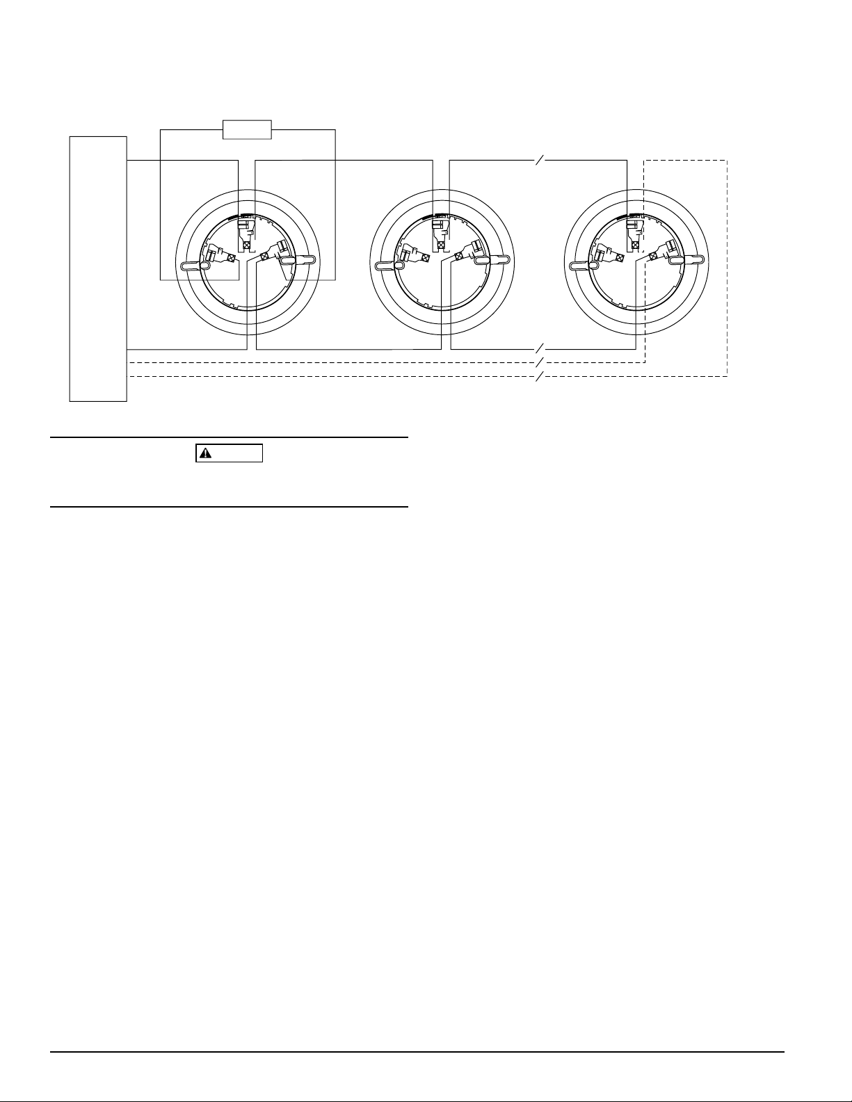
Figure 1. Wiring diagram:
CONTROL PANEL
U.L. LISTED COMPATIBLE
REMOTE ANNUNCIAT OR
+-
+
2
3
1
-
+
WARNING
CLASS A OPTIONAL WIRING
CAUTION: Do not loop wire under terminal 1 or 2.
Break wire run to provide supervision of connections.
The sensor cannot detect smoke if the dust cover is installed.
2. Tamper-Resist Feature
The sensor bases include a tamper-resist feature that,
when it is enabled, prevents r emoval of the sensor without the use of a tool. See the sensor base installation instruction manual for details on the use of this feature.
3. After all sensors have been installed, apply power to the
control unit.
2
3
1
2
3
1
A78-1253-01
Sensors must be tested after installation and periodic maintenance. Test the sensor as follows:
A. Test Magnet (Model No. M02-04-00)
1. Place the magnet against the cover opposite the test
module socket to activate the test feature (see Figur e 2).
2. The LED’s should latch on within 10 seconds, indicating alarm and annunciating the panel.
B. Test Tool (Model No. MOD400R)
Use the MOD400R with a DMM or Voltmeter to check
the sensor sensitivity as described in the MOD400R
manual.
4. Test the sensor by positioning a test magnet against the
sensor plastic directly opposite the test meter socket
(Figure 2). The alarm level should be recognized by the
NOTE: The MOD400R can be used to test the sensitivity of
only those sensors connected to control panels that
do NOT use drift compensation.
panel and the LED controlled by communication command from the panel.
C. Aerosol Generator (Gemini 501) per NFPA 72
The field test tool is the GEMINI Model 501 aerosol gen-
5. The reset of the sensor LED is controlled by communication command from the panel.
erator. Set the generator to represent 4%/ft to 5%/ft obscuration as described in the GEMINI 501 manual. Using
the bowl shaped applicator, apply aerosol until unit
Testing
alarms.
Before testing, notify the proper authorities that the smoke
sensor system is undergoing maintenance, and therefore
the system will be temporarily out of service. Disable the
zone or system undergoing maintenance to prevent un-
NOTE: This test only verifies smoke's ability to enter the
sensing chamber and initiate an alarm. It does
NOT test sensitivity.
wanted alarms.
Notify the proper authorities that the system is back on line.
D500-40-00 2 I56-1436-00
Page 3
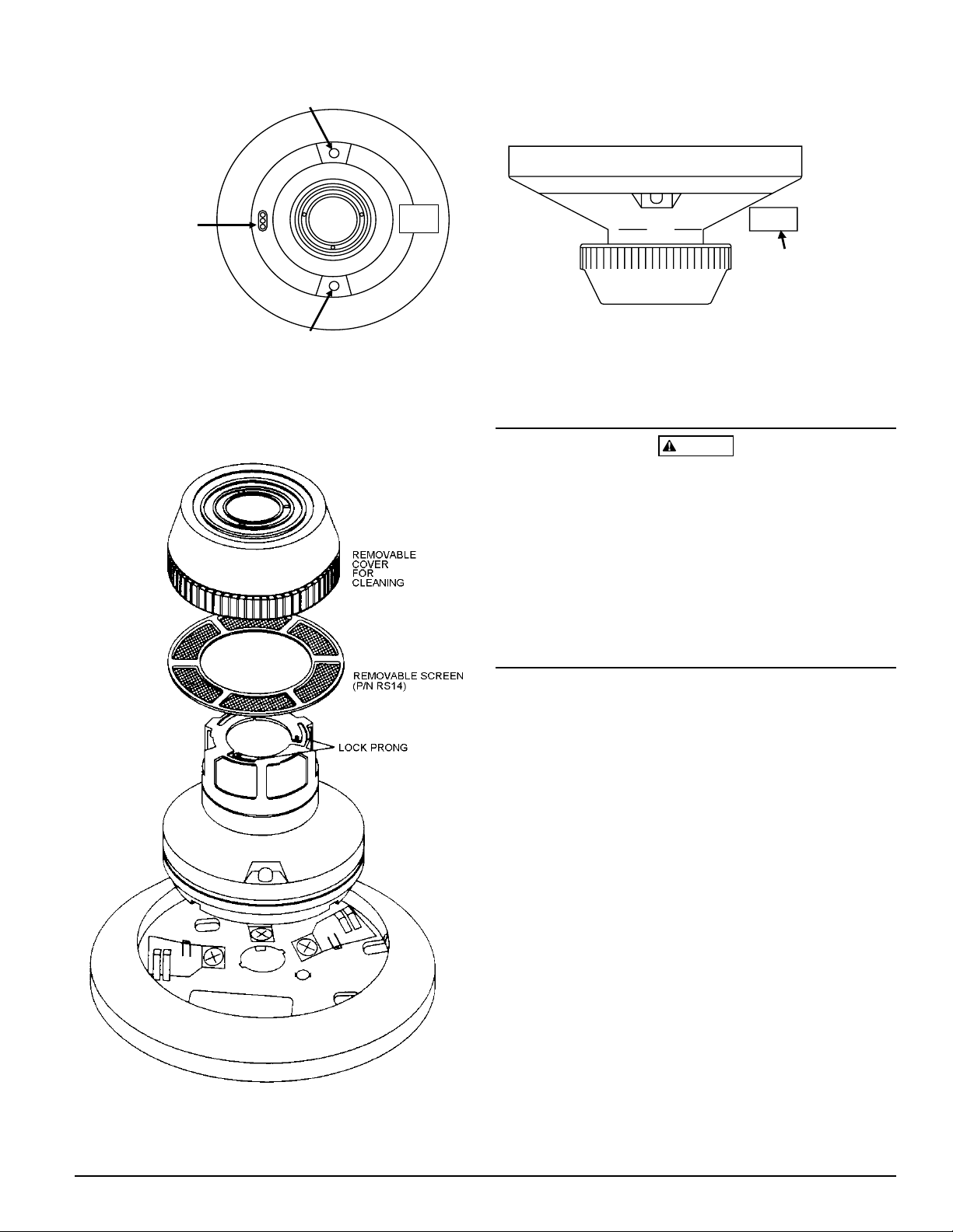
Figure 2. Views showing position of test magnet:
LED
EST MODULE
Figure 3:
SOCKET
LED
TEST
MAGNET
PAINTED
SURFACE
TEST
MAGNE
A78-1978-00
Sensors that fail these tests should be cleaned as described
under CLEANING and retested. If the sensors still fail these
tests they should be returned for repair.
CAUTION
Dust covers are an effective way to limit the entry of dust
into smoke detector sensing chambers. However, they may
not completely prevent airborne dust particles from enter-
ing the detector. Therefore, System Sensor recommends the
removal of detector s before beginning construction or other
dust producing activity.
Be sure to remove the dust covers from any sensors that
were left in place during construction as part of returning
the system to service.
A78-1938-00
Cleaning the Sensor
NOTE: Before cleaning, notify the proper authorities that
the smoke sensor system is undergoing maintenance and will be temporarily out of service. Disable the loop or system undergoing maintenance to
prevent unwanted alarms.
It is recommended that the sensor be removed from its
mounting base for easier cleaning and that sensors be
cleaned at least once a year.
To remove the cover, depress the three lock prongs on the
top of the cover and rotate it counterclockwise to remove
the cover and screen assembly. Remove the screen and
clean the cover and screen assembly. Remove the screen
and clean it (Figure 3). Use a vacuum cleaner to remove
dust from the sensing chamber. Cover removal tools
(CRT400) and replacement screens (RS14) are available
upon request.
After cleaning, snap the screen into the cover. Then place
the cover and screen assembly on the sensor and rotate it
clockwise until it is locked in place. Test the sensor.
D500-40-00 3 I56-1436-00
Page 4

The Limitations of Property Protection Smoke Sensors
This smoke sensor is designed to activate and initiate emergency action,
but will do so only when it is used in conjunction with an authorized fire
alarm system. This sensor must be installed in accordance with NFPA
standard 72.
Smoke sensors will not work without power. AC or DC powered smoke
sensors will not work if the power supply is cut off.
Smoke sensors will not sense fires which start where smoke does not
reach the sensors. Smoldering fires typically do not generate a lot of heat
which is needed to drive the smoke up to the ceiling where the smoke sensor is usually located. For this reason, there may be large delays in detecting a smoldering fire with either an ionization type sensor or a
photoelectric type sensor . Either one of them ma y alarm only after flaming
has initiated which will generate the heat needed to drive the smoke to the
ceiling.
Smoke from fires in chimneys, in walls, on roofs or on the other side of a
closed door(s) may not reach the smoke sensor and alarm it. A sensor
cannot detect a fire developing on another lev el of a building quickly or at
all. For these reasons, sensors shall be located on every level and in ev-
ery bedroom within a building.
Smoke sensors have sensing limitations, too. Ionization sensors and
photoelectric sensors are required to pass fire tests of the flaming and
WARNING
smoldering type. This is to ensure that both can detect a wide range of
types of fires. Ionization sensors offer a broad range of fire sensing capability but they are somewhat better at detecting fast flaming fires than
slow smoldering fires. Photoelectric sensors sense smoldering fires better
than flaming fires which have little , if any, visible smoke. Because fires develop in different ways and are often unpredictable in their growth, neither type of sensor is always best, and a given sensor may not always
provide early warning of a specific type of fire.
In general, sensors cannot be expected to pr ovide w arnings for fires r esulting from inadequate fire protection practices, violent explosions, escaping
gases which ignite, improper storage of flammable liquids like cleaning
solvents which ignite, other similar safety hazards , ar son, smoking in bed,
children playing with matches or lighters, etc . Smok e sensor s used in high
air velocity conditions may have a dela y in alarm due to dilution of smok e
densities created by frequent and rapid air exchanges. Additionally, high
air velocity environments may create increased dust contamination, demanding more frequent maintenance.
Smoke sensors cannot last forever. Smoke sensors contain electronic
parts. Even though smoke sensor s are made to last over 10 years, any part
can fail at any time. Therefor e , smok e sensors shall be r eplaced after being
in service for 1 0 years . The smoke sensor s ystem that this sensor is used in
must be tested regularly per NFPA 72. This smoke sensor should be
cleaned regularly per NFPA 72 or at least once a year.
Three-Year Limited Warranty
System Sensor warrants its enclosed smoke detector to be free from defects in materials and workmanship under normal use and service for a
period of three years from date of manufacture. System Sensor makes no
other express warranty for this smoke detector. No agent, representative,
dealer, or employee of the Company has the authority to increase or alter
the obligations or limitations of this Warranty. The Company’s obligation
of this W arr anty shall be limited to the repair or replacement of an y part of
the smoke detector which is found to be defective in materials or workmanship under normal use and service during the three year period commencing with the date of manufacture. After phoning System Sensor’s toll
free number 800-SENSOR2 (736-7672) for a Return A uthorization number,
send defective units postage prepaid to: System Sensor, Repair Depart-
ment, RA #__________, 3825 Ohio Avenue, St. Charles, IL 60174. Please
include a note describing the malfunction and suspected cause of failure.
The Company shall not be obligated to repair or replace units which are
found to be defective because of damage, unreasonable use, modifications, or alterations occurring after the date of manufacture. In no case
shall the Company be liable for any consequential or incidental damages
for breach of this or any other Warranty, expressed or implied whatsoe v er,
even if the loss or damage is caused by the Compan y’s negligence or fault.
Some states do not allow the exclusion or limitation of incidental or consequential damages, so the above limitation or exclusion may not apply to
you. This Warranty gives you specific legal rights, and you may also have
other rights which vary from state to state.
D500-40-00 4 I56-1436-00
© System Sensor 1999
 Loading...