

Page 1
INSTALLATION AND MAINTENANCE INSTRUCTIONS
WARNING
1451 Plug-in Ionization
3825 Ohio Avenue, St. Charles, Illinois 60174
Smoke Detector
Specifications
Size
Height: 2.4 inches (6.1 cm)
Diameter: 4.0 inches (10.1 cm)
Weight: 0.6 lb. (277 g)
Operating Temperature Range: 0°C to +49°C (32°F to 120°F)
Operating Humidity Range: 10% to 93% Relative Humidity Non-condensing
Latching Alarm: Reset by momentary power interruption.
Before installing
Please thoroughly read the System Sensor manual A051003, Applications Guide for System Smoke Detectors, which
provides detailed information on detector spacing, placement, zoning, wiring, and special applications. Copies of
this manual are available at no charge from System Sensor.
(For installation in Canada refer to CAN/ULC-S524, Standard for the Installation of Fire Alarm Systems, and CEC
Part 1, Sec. 32.)
NOTICE: This manual should be left with the owner/user
of this equipment.
NOTICE: Model 1451 is a direct replacement for Honeywell
model TC805C1000
IMPORTANT: This sensor must be tested and maintained
regularly following NFPA 72 requirements. This sensor
should be cleaned at least once a year.
General Description
Model 1451 dual chamber ionization detectors utilize stateof-the-art, unipolar sensing chambers. These detectors are
designed to provide open area protection, and to be used
with compatible UL-listed control panels only. The capability of plugging these detectors into a variety of special
bases makes them more versatile than equivalent directwired models.
Two LEDs on each detector light to provide a local 360°
visible alarm indication. Remote LED annunciator capability is available as an optional accessory. These detectors
also have the latching alarm feature. The alarm can be
reset only by a momentary power interruption. For testing, these detectors have an internal magnetically activated
reed switch.
Model 1451 has been approved for marine use in dry locations by Underwriters Laboratory, Inc. The detector is to be
used in dry interior locations only.
Spacing
Spacing of 30 ft. on a smooth ceiling as per NFPA 72E.
Where conditions or response requirements vary, other
spacing may apply.
Base Selection And Wiring Guide
Refer to the installation instructions for the plug-in detector
bases for wiring instructions. System Sensor has available a
variety of detector bases for this smoke detector, including
2-wire applications with and without relays and/or current
limiting resistors, 4-wire and 120VAC applications. (Note:
the 120VAC detector base is not available in Canada.)
All bases are provided with screw terminals for power,
ground, remote annunciator connections, and relay contact
connections, if applicable. The electrical ratings for each
detector-base combination are also included in the base installation instructions.
Installation
NOTE: All wiring must conform to applicable local codes,
ordinances, and regulations.
NOTE: Verify that all detector bases are installed, that the
initiating-device circuits have been tested, and that the wiring is correct.
Remove power from initiating-device circuits before installing detectors.
1-800-SENSOR2, FAX: 630-377-6495
www.systemsensor.com
D400-01-01 1 I56-0278-008R
Page 2
1. Install Detectors:
CAUTION
CAUTION
PAINTED
SURFACE
TEST
MAGNET
TEST
MAGNET
LED
TEST MODULE
SOCKET
LED
a. Place the detector into the detector base.
b. Turn the detector clockwise until the detector drops
into place.
c. Continue turning detector clockwise to lock it in place.
2. Tamper-proof Feature
The detector bases include a feature that, when acti-
vated, prevents removal of the detector without the use
of a tool. See the installation instruction manual of the
detector base for details in using this feature.
3. After all detectors have been installed, apply power to
the control unit.
4. Test the detector as described under TESTING.
5. Reset the detector at the system control panel.
6. Notify the proper authorities that the system is in operation.
Dust covers can be used to help limit dust entry to the detector, but they are not a substitute for removing the detector during building construction. Remove any dust covers
before placing system in service.
Smoke detectors are not to be used with detector guards
unless the combination has been evaluated and found
suitable for that purpose.
Before testing the detector, look for the presence of the
flashing LEDs. If they do not flash, either power has been
lost to the detector (check the wiring), or it is defective
(return for repair).
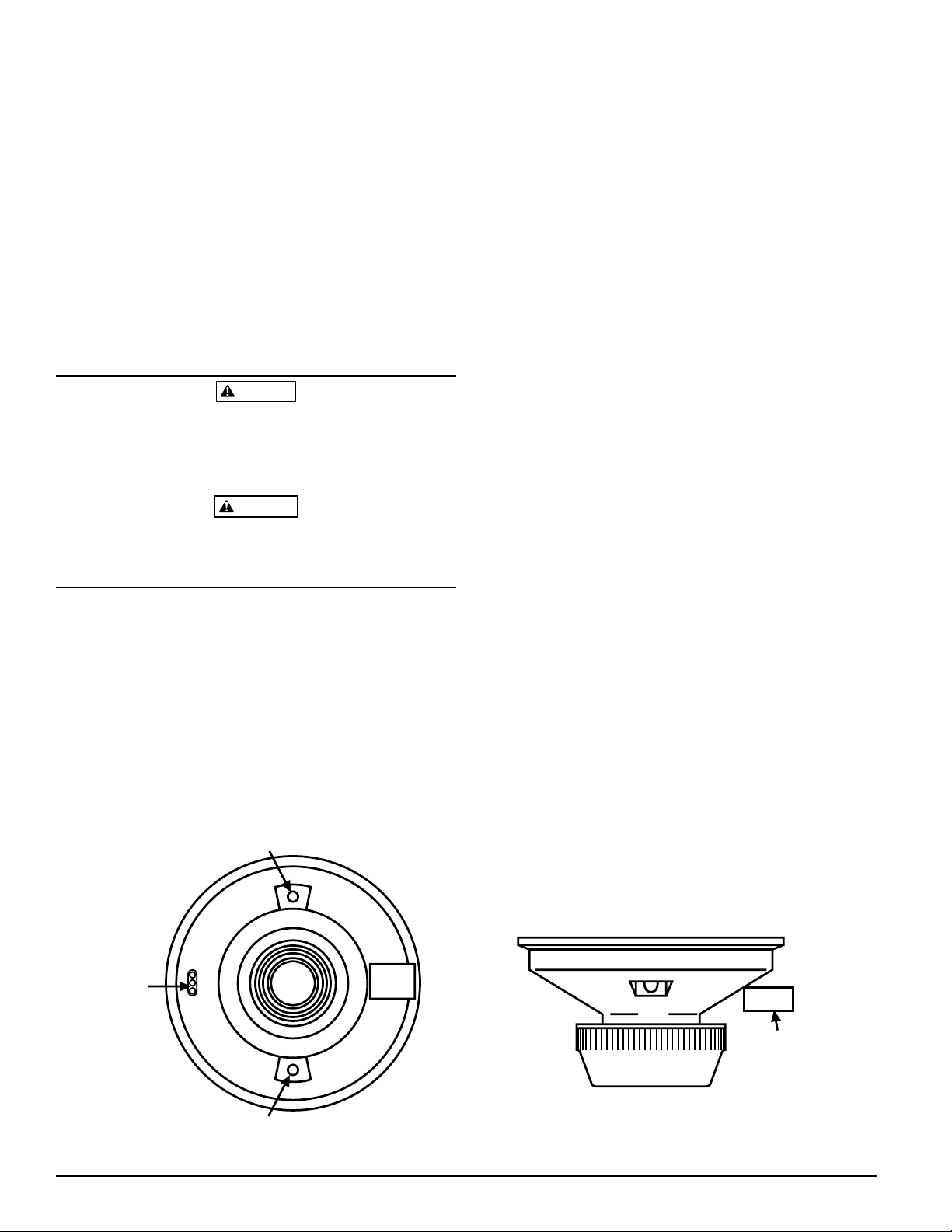
A. Test Magnet (System Sensor Model No. M02-04-00)
1. Place the magnet against the cover opposite the test
module socket. (See Figure 1.)
2. The LEDs on the detector should latch on within
30 seconds.
3. Reset the detector at the system control panel.
B. Test Module (System Sensor Model No. MOD400R)
The MOD400 or MOD400R is used with a digital or an-
alog voltmeter to check the detector sensitivity as de-
scribed in the test module’s manual.
C. Aerosol Generator (Gemini 501)
Set the generator to represent 4%/ft. to 5%/ft. obscura-
tion as described in the Gemini 501 manual. Using the
bowl shaped applicator, apply aerosol until unit alarms.
Notify the proper authorities that the system is back on line.
Detectors that fail these tests should be cleaned as described
under MAINTENANCE and retested. If the detectors still
fail these tests they should be returned for repair.
Testing
Before testing, notify the proper authorities that the smoke
detector system is undergoing maintenance and will temporarily be out of service. Disable the zone or system undergoing maintenance to prevent unwanted alarms.
Detectors must be tested after installation and periodic
maintenance. The 1451 may be tested as follows:
Figure 1. Bottom and side views showing test magnet position:
S0137-00
D400-01-01 2 I56-0278-008R
Page 3

It is recommended that the detector be removed from its
LOCK PRONG
REMOVABLE SCREEN
(P/N RS14)
REMOVABLE
COVER
FOR
CLEANING
SENSING CHAMBER
mounting base to facilitate easier cleaning. The detector is
cleaned as follows:
NOTE: Before removing the detector, notify the proper
authorities that the smoke detector system is undergoing
maintenance, and will temporarily be out of service. Disable the zone or system undergoing maintenance to prevent unwanted alarms.
1. Remove the detector screen and cover assembly by de
pressing the three lock prongs on the top of the cover,
rotating the cover counterclockwise, and pulling the
screen and cover assembly away from the detector. (See
Figure 2.) Usage of a System Sensor CRT400 cover removal tool is recommended.
2. Remove the screen from the cover.
3. Use a vacuum cleaner to remove dust from the screen,
the cover, and the sensing chamber.
4. After cleaning, snap the screen into the cover, then place
the cover and screen assembly on the detector, turning
clockwise until it is locked in place.
5. Reinstall the detector.
6. Test the detector as described under TESTING.
7. Notify the proper authorities that the system is back on line.
Figure 2:Maintenance
-
S0138-00
D400-01-01 3 I56-0278-008R
Page 4

Please refer to insert for the Limitations of Fire Alarm Systems
Three-Year Limited Warranty
System Sensor warrants its enclosed product to be free from defects in
materials and workmanship under normal use and service for a period
of three years from date of manufacture. System Sensor makes no other
express warranty for the enclosed product. No agent, representative,
dealer, or employee of the Company has the authority to increase or alter
the obligations or limitations of this Warranty. The Company’s obliga
tion of this Warranty shall be limited to the replacement of any part of
the product which is found to be defective in materials or workmanship under normal use and service during the three year period commencing with the date of manufacture. After phoning System Sensor’s
toll free number 800-SENSOR2 (736-7672) for a Return Authorization
number, send defective units postage prepaid to: System Sensor, Returns
D400-01-01 4 I56-0278-008R
©2006 System Sensor
Department, RA #__________, 3825 Ohio Avenue, St. Charles, IL 60174.
Please include a note describing the malfunction and suspected cause
of failure. The Company shall not be obligated to replace units which
are found to be defective because of damage, unreasonable use, modi
fications, or alterations occurring after the date of manufacture. In no
case shall the Company be liable for any consequential or incidental
damages for breach of this or any other Warranty, expressed or implied
whatsoever, even if the loss or damage is caused by the Company’s
negligence or fault. Some states do not allow the exclusion or limitation of incidental or consequential damages, so the above limitation or
exclusion may not apply to you. This Warranty gives you specific legal
rights, and you may also have other rights which vary from state to state.
-
 Loading...