

Page 1
D200-51-00 1 I56-548-07R
1251 Plug-in Intelligent Ionization
Sensor with Communications
INSTALLATION AND MAINTENANCE INSTRUCTIONS
A Division of Pittway
3825 Ohio Avenue, St. Charles, Illinois 60174
1-800-SENSOR2, FAX: 630-377-6495
Before Installing
Please read the system wiring and installation manual, I56-
407. This manual includes detailed information on sensor
spacing, placement, zoning, and special applications.
Copies of this manual are available from System Sensor.
General Description
Model 1251 intelligent ionization sensor uses a state-of-theart sensing chamber. These sensors are designed to provide
open area protection and are intended for use with compatible control panels only.
Two LEDs on each sensor light to provide a local, visible
sensor indication. The LEDs can be latched on by code
command from the control panel for an alarm indication.
The LEDs can also be unlatched to the normal condition by
code command. Remote LED annunciator capability is also
available as an optional accessory (RA400Z).
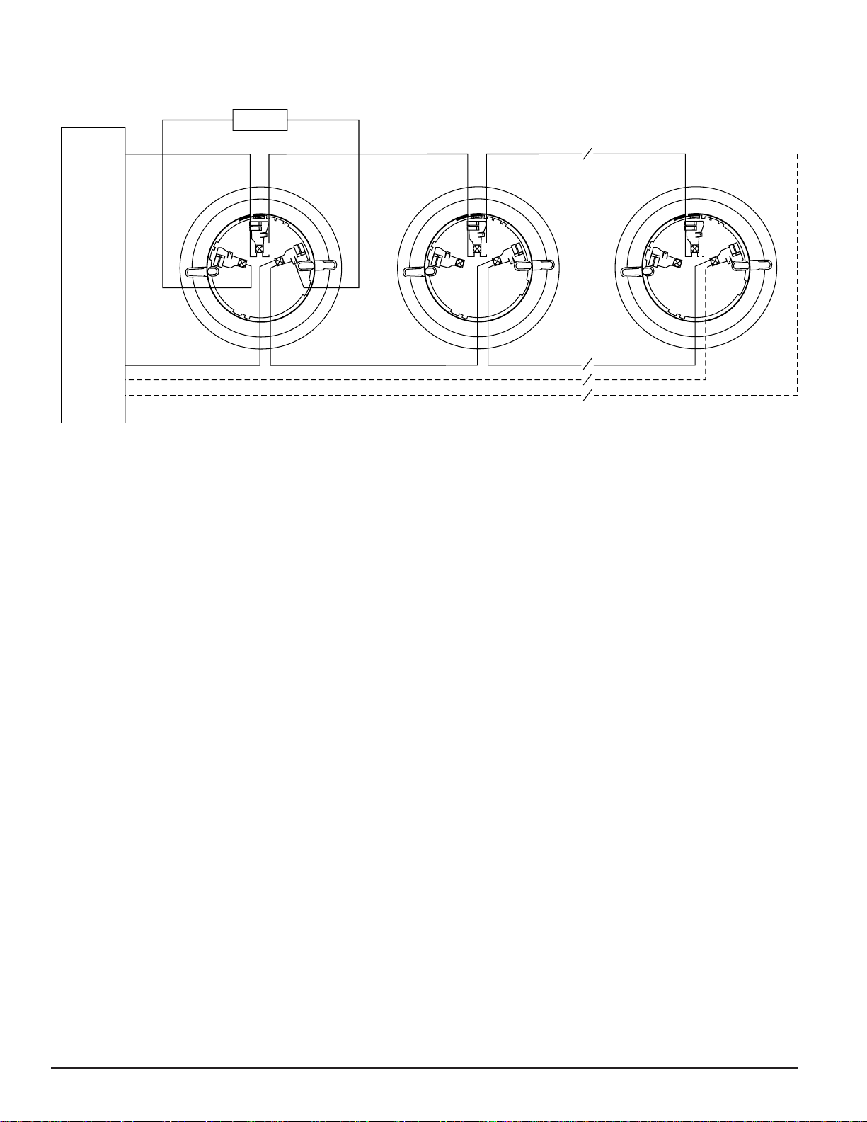
Wiring Guide
Refer to the installation instructions for the plug-in base
being used. As indicated in Figure 1, terminals for power,
ground, and the optional RA400Z Remote Annunciator are
included in the base. Base Models B210LP (shown in Figure
1) and B501 are electrically identical.
NOTE: All wiring must conform to all applicable codes,
ordinances, and regulations.
NOTE: Verify that all sensor bases are installed and that
polarity of the wiring is correct at each base.
Specifications
Operating Voltage Range: 15 to 32 VDC
Max. Avg. Standby Current: 300µA @ 24 VDC (one communication every 5 sec. with LED blink enabled)
Max. Alarm Current (LED on): 6.5 mA @ 24 VDC
Operating Humidity Range: 10% to 93% Relative Humidity, noncondensing
Operating Temperature Range: 0° to 49°C (32° to 120°F)
Height: 1.7 inches (43 mm) installed in B210LP Base
Diameter: 6.1 inches (155 mm) installed in B210LP Base
4.1 inches (104 mm) installed in B501 Base
Weight: 3.6 oz. (102 g)
Disconnect loop power before installing sensors.
1. Sensor Installation
a. Set the sensor to the desired address and record that
address on the label attached to the base.
b. Insert the sensor into the base and rotate it clockwise
until it drops into place.
c. Continue to rotate the sensor until it locks into the
base.
Dust covers are an effective way to limit the entry of dust
into smoke detector sensing chambers. However, they may
not completely prevent airborne dust particles from entering the detector. Therefore, System Sensor recommends the
removal of detectors before beginning construction or other
dust producing activity.
Be sure to remove dust covers from any sensors that were
left in place during construction as part of returning the
system to service.
CAUTION
WARNING
Page 2
D200-51-00 2 I56-548-07R
3
2
1
3
2
1
3
2
1
+
-
-
+
U.L. LISTED COMPATIBLE
CONTROL PANEL
CLASS A OPTIONAL WIRING
REMOTE ANNUNCIAT OR
+-
CAUTION: Do not loop wire under terminal 1 or 2.
Break wire run to provide supervision of connections.
Figure 1:
2. Tamper-Resistance
Model 1251 includes a tamper-resistant capability that
prevents their removal from the bracket without the use
of a tool. Refer to the base manual for details on making
use of this capability.
3. After all sensors have been installed, apply power to the
system.
4. See Figure 2. Test the sensor by positioning a test mag-
net against the sensor plastic just to the left of LED1.
The alarm level should be recognized at the panel and
the LED controlled by communication command from
the panel.
5. Reset the sensor by communication command from the
panel.
Testing
Detectors must be tested after installation and following
periodic maintenance. However, before testing, notify the
proper authorities that the smoke detector system is undergoing maintenance and the system will be temporarily out
of service. Disable the zone or system undergoing maintenance to prevent unwanted alarms.
In addition, check to ensure that the LEDs blink. If they do
not, power has been lost to the detector (check the wiring),
or it is defective (return it for repair).
Test the sensors as follows:
A. Test Magnet (p/n M02-04-01 or M02-09-00)
1. Test the sensor by positioning the optional test magnet against the sensor plastic just to the left of LED1,
as shown in Figure 2.
2. Both LEDs should latch on within 30 seconds, indicating an alarm and annunciating the panel.
B. Aerosol Generator in accordance with NFPA 72.
The Gemini Model 501 aerosol generator can be used
to test the sensor. Set the generator to represent 4%/ft to
5%/ft obscuration, following the instructions in the generator manual. Use a bowl shaped applicator to apply
aerosol to the sensor. It should alarm after 30 seconds.
Page 3

D200-51-00 3 I56-548-07R
Figure 2. Test Magnet positioning:
Figure 3:
Cleaning
Before cleaning, notify the proper authorities that the system is undergoing maintenance and will be temporarily out
of service. Disable the system to prevent unwanted alarms.
1. Remove the sensor to be cleaned from the system.
2. Remove the sensor cover. Use a small standard screw-
driver to release each of the four cover removal tabs that
hold the cover in place.
3. Vacuum the outside of the screen carefully without
removing it.
4. Remove the sensor screen. Pull the screen straight away
from the sensing chamber until it snaps out of place.
Replacement screens are available.
5. Use a vacuum cleaner or clean, compressed air to
remove dust and debris from the sensing chamber.
6. Reinstall or replace the sensing chamber screen by slid-
ing the edge without the tabs over the sensing chamber.
Make sure that one of the Screen Contacts touches the
Circuit Board Contact.
7. Reinstall the sensor cover. Use the LEDs to align the
cover with the sensor. Snap the cover into place.
8. When all sensors have been cleaned, restore power to
the system and test the sensor(s) as described in the
TESTING section of this manual.
A78-2424-07
Page 4

D200-51-00 4 I56-548-07R
©
2000 System Sensor
Three-Year Limited Warranty
System Sensor warrants its enclosed smoke detector to be free from
defects in materials and workmanship under normal use and service for a
period of three years from date of manufacture. System Sensor makes no
other express warranty for this smoke detector. No agent, representative,
dealer, or employee of the Company has the authority to increase or alter
the obligations or limitations of this Warranty. The Company’s obligation
of this Warranty shall be limited to the repair or replacement of any part
of the smoke detector which is found to be defective in materials or workmanship under normal use and service during the three year period commencing with the date of manufacture. After phoning System Sensor’s toll
free number 800-SENSOR2 (736-7672) for a Return Authorization number,
send defective units postage prepaid to: System Sensor, Repair
Department, RA #__________, 3825 Ohio Avenue, St. Charles, IL 60174.
Please include a note describing the malfunction and suspected cause of
failure. The Company shall not be obligated to repair or replace units
which are found to be defective because of damage, unreasonable use,
modifications, or alterations occurring after the date of manufacture. In no
case shall the Company be liable for any consequential or incidental damages for breach of this or any other Warranty, expressed or implied whatsoever, even if the loss or damage is caused by the Company’s negligence
or fault. Some states do not allow the exclusion or limitation of incidental
or consequential damages, so the above limitation or exclusion may not
apply to you. This Warranty gives you specific legal rights, and you may
also have other rights which vary from state to state.
Please refer to insert for the Limitations of Fire Alarm Systems
 Loading...