

Page 1

XP Series PM Standard Procedure
Customer Support Headquarters
Sysmex Corporation
Version 2 March 4, 2013
Page 2

(Version 2)
XP Series Preventive Maintenance Checklist
Check Items Schedule Check Remarks
Check setting
values
Print setting values □
HOST Output Setting OFF □
Check data
before
maintenance
Check background data □
Check data using control
material or samples
□
Check adjustment
values before
maintenance
□
*
SRV
Disassemble and clean SRV □
Clean the tray □
Replace whole blood tube
manually
□
Rinse Cup
Clean Rinse Cup □
Replace Tube Pharmed for
Waste Line
Once a year □
Waste Chamber
Disassemble and rinse
Waste Chamber
□
Replace Waste Chamber
Drain Line silicon tubes.
Once a year □
Replace Waste Chamber
Every 5 years (or as
needed)
□
Bellows Unit
Disassemble and rinse
Bellows Unit, Clean needle
□
Rinse orifice tube □
Pneumatic Unit
Rinse Trap Chamber □
Replace Pneumatic Unit
protection filter
Every 2 years □
Replace Compressor
Positive pressure is no
more than 0.22 MPa or
negative pressure is no
more than -0.04MPa.
□
Transducer
Clean WBC transducer
aperture
□
Clean RBC transducer
aperture
□
Clean inside of Transducer
Assy
□
Pressure
adjustment
0.05MPa pressure
adjustment
□
*
-0.0333MPa pressure
adjustment
□
*
HYDRAULIC
UNIT
Transducer cleaning
sequence
□
Waste Chamber Rinse
Sequence
□
Other
adjustments
Adjust HGB background
count level
□
*
Adjust WBC clog level □ *
Adjust RBC clog level □ *
Main Unit, Interior
Clean inside of Main Unit □
Lubricate mechanism □
Checking data
Check background count
level
□
Check data using control
material or samples
□
Page 3
(Version 2)
Check Items Schedule Check Remarks
Main Unit,
Exterior
Clean Main Unit covers □
Clean peripheral device
(printer etc.)
Cleaning
□
Check after
maintenance
Restore host output settings □
Check program version □ *
Cycle counts □ *
Final performance check □
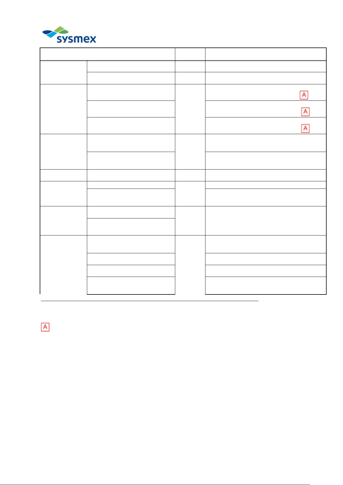
* “Schedule” is only a guideline and differs according to status of use.
* If “Schedule” is blank, it means that the items need to be checked for every periodic maintenance.
* The replaced parts which are not in the check list and the parts that a service engineer recommends to replace in
future are mentioned in “Remarks”.
【Details of Adjustment Items】
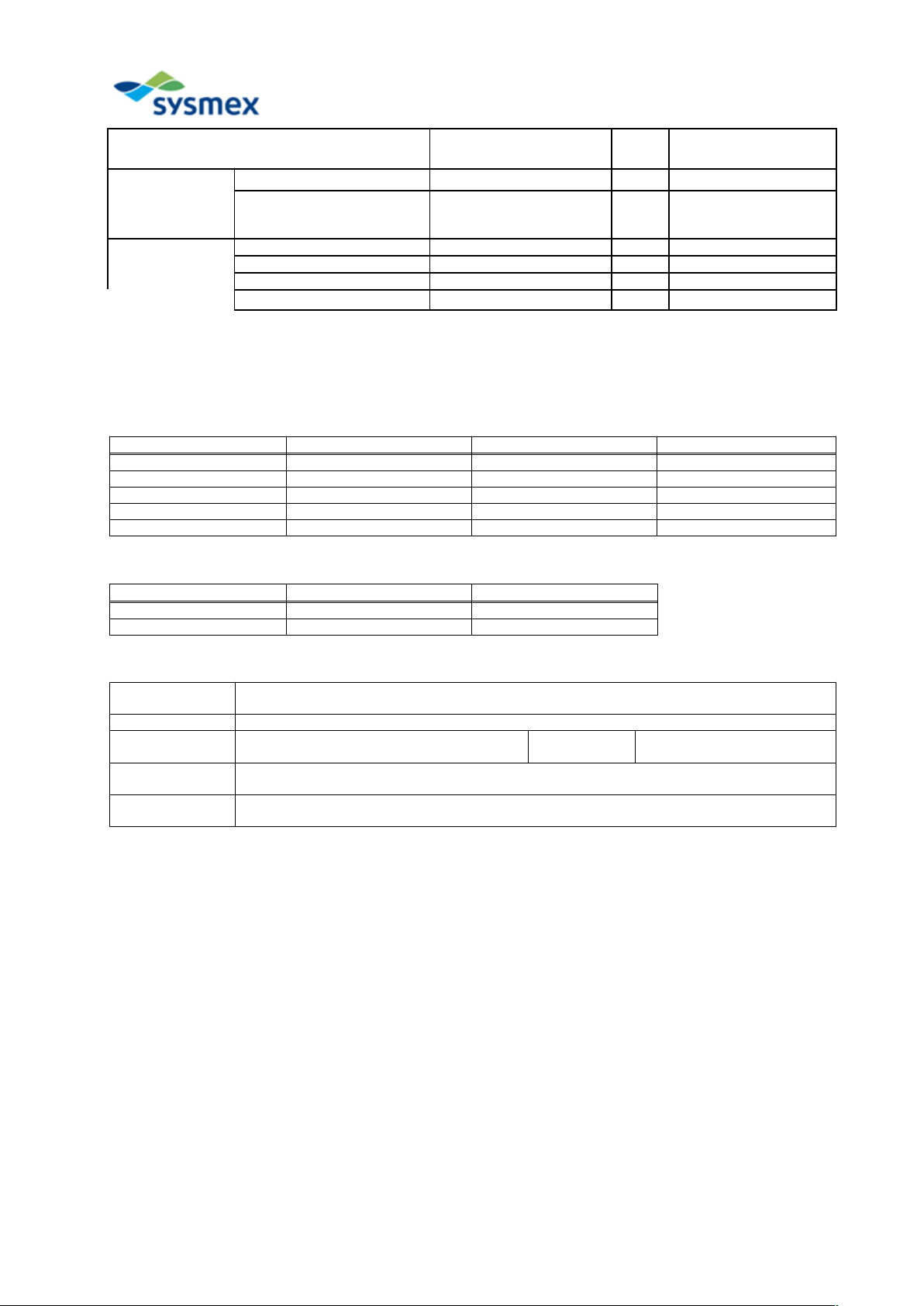
Adjustment Items Specified Range Value Before Adjustment Value After Adjustment
0.05MPa pressure 0.05 +/- 0.01 (MPa)
-0.0333MPa pressure -0.0333 +/- 0.0013 (MPa)
HGB background convert 2000+/-200
WBC clog level 100.0+/-1.0
RBC clog level 100.0+/-1.0
【Details of Check Items】
Adjustment Items Specified Range Confirmed Value
Program Version Cycle counts -
* Refer to Job List or QC Chart for control, or sample analysis values.
Maintenance
Report No.
Facility Name
Instrument
Name
XP-100/XP-300 Serial No.
Maintenance
Date
Name of Service
Engineer
Page 4
(Version 2)
XP Series PM Standard Procedure
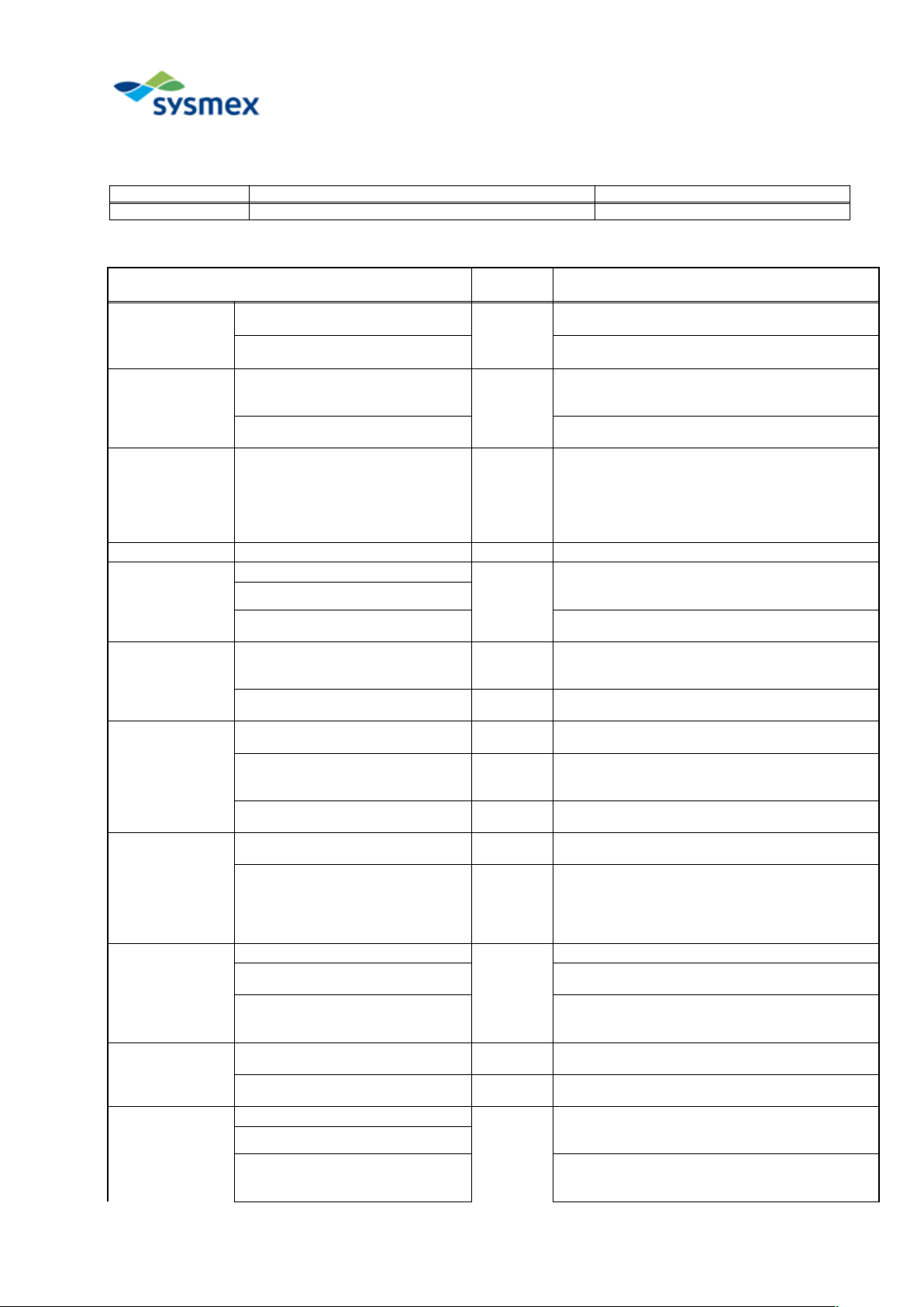
[Required jigs and controls, etc.]
Code Product Name Remarks
- EIGHTCHECK Control blood
Items to be checked
Operation
time
Procedure
Checking setting
values
Print Setting Value
5 min.
Go to [Menu] -> [Service] -> [Settings] -> [Print
Settings] to print all setting values.
HOST Output Setting OFF
Go to [Menu] -> [Settings] -> [Host Output
Settings] to change "Connection" to "Disconnect".
Data analysis
before
maintenance
Check background count level
10 min.
Analyze normal sample or control material and
print average values or record them using stored
data/QC chart.
Check data using control material
or samples
Perform background check.
Check adjustment
values before
maintenance
HGB background convert
WBC clog level
RBC clog level
0.05MPa
-0.0333MPa
Go to [Menu] -> [Service] -> [Service Data]. Print
out and check service data for the latest samples.
Go to [Menu] -> [Maint.] -> [Status Display] to
check pressure.
Removing covers Remove front and side covers.
SRV
Disassemble and clean SRV
15 min.
Use CELLCLEAN and distilled water to perform
cleaning.
(Refer to Instructions for Use Chapter 12.)
Clean the tray
Replace the aspiration pipette
Replace PIPETTE NO.57 using FITTING NO. 9-
A.
Rinse Cup
Clean Rinse Cup 5 min.
Use CELLCLEAN and distilled water to perform
cleaning.
(Refer to Instructions for Use Chapter 12.)
Replace Tube Pharmed for Waste
Line
5 min.
Replace by using Tube Pharmed 1/4 IN X 1/8 IN.
(Refer to Service Manual "Schematics".)
Waste Chamber
Replace Waste Chamber (Every 5
years)
5 min. Replace WASTE CHAMBER ASSY NO.35.
Disassemble and clean Waste
Chamber (when not replacing
Waste Chamber).
5 min.
Wipe the interior of the chamber and the float
switch using gauze impregnated with
CELLCLEAN.
Replace Waste Chamber Drain
Line silicon tubes.
5 min.
Replace silicon tube F739-8.
(Refer to Service Manual "Schematics".)
Bellows Unit
Disassemble and rinse Bellows Unit 5 min.
Wipe the unit and the needle tip using gauze
impregnated with ethanol.
Clean orifice tube 5 min.
Inject ethanol using an injection syringe to clean.
If the tube is extremely dirty, replace the whole
tube.
TUBE POLYURETHANE 1.8MMX3.4MM
(1400mm)
Pneumatic Unit
Rinse Trap Chamber
30 min.
Clean Trap Chamber using distilled water.
Replace Pneumatic Unit protection
filter
Replace FILTER NO. 9.
Replace Compressor
Replace by using KX-21 Pneumatic Unit (XP
series).
(Refer to Service Manual Parts List.)
Pressure and
vacuum
adjustment
0.5kg/cm2(0.05MPa)
Pressure adjustment
10 min.
Adjust pressure to 0.05Mpa using Regulator.
(Refer to Instructions for Use Chapter 12.)
250 mmHg (-0.0333MPa)
Vacuum adjustment
5 min.
Adjust vacuum to -0.0333MPa using the bellows
unit. (Refer to Instructions for Use Chapter 12.)
Transducer
Clean WBC transducer aperture
10 min.
Apply CELLCLEAN to a brush for clog removal
and clean the aperture. (Refer to Instructions for
Use Chapter 12.)
Clean RBC transducer aperture
Clean inside of Transducer
Remove dust, etc. and wipe with gauze
impregnated with ethanol. Then, wipe with dry
gauze.
Page 5
(Version 2)
Items to be checked
Operation
time
Procedure
HYDRAULIC
UNIT
Perform transducer cleaning
sequence.
7 min.
Go to [Menu] -> [Maint.] -> [Clean Transducer] to
perform the sequence.
Perform Waste Chamber Rinse
Sequence
15 min.
Go to [Menu] -> [Maint.] -> [Clean W. Chamber] to
perform the sequence.
Other
adjustments
Adjust HGB background count level
5 ~
10 min.
Adjust VR 1 of PCB NO.20034/PCB. NO. 2135.
(Refer to Service Manual "Adjustment".)
Adjust WBC clog level
Adjust VR 6 of PCB NO.20034/PCB. NO. 2135.
(Refer to Service Manual "Adjustment".)
Adjust RBC clog level
Adjust VR 7 of PCB NO.20034/PCB. NO. 2135.
(Refer to Service Manual "Adjustment".)
Main Unit, Interior
Clean inside of Main Unit
10 min.
Remove dust, etc. from inside of Main Unit.
Use vacuum cleaner to remove dust, etc. from the
printer mechanism.
Lubricate mechanism
Apply silicon grease to air cylinder shaft for
driving SRV.
Apply BIRAL spray to linear slider for rinse cup.
Cover installation
Install instrument covers which were removed
previously.
Check data
Check background count level
10 min.
Check that the blank error has not occurred.
Check data using control material
or samples
Analyze normal sample or control material (at
least two times) and print average values or
record them using stored data/QC chart.
Main Unit,
Exterior
Clean Main Unit covers
5 min.
Remove dust, etc. and wipe with gauze
impregnated with ethanol. Then, wipe with dry
gauze.
Use vacuum cleaner to remove dust, etc. from the
printer mechanism.
Cleaning peripheral device (printer,
etc.)
Checking
performance after
maintenance
Restore host output settings
15 min.
Go to [Menu] -> [Settings] -> [Host Output
Settings] to restore "Connection" to the state
before maintenance is carried out.
Check program version
Go to [Menu] -> [Maint.] -> [Status Display] to
check version.
Cycle counts
Go to [Menu] -> [Maint.] -> [Status Display] to
check Total C.
Final performance check
Turn the power OFF and ON and start the
instrument in the user mode to check sample
analysis is performed without errors.
* Operation time is an approximation and does not include removal of covers, etc.
ECR 312J003
Page 6
(Version 2)
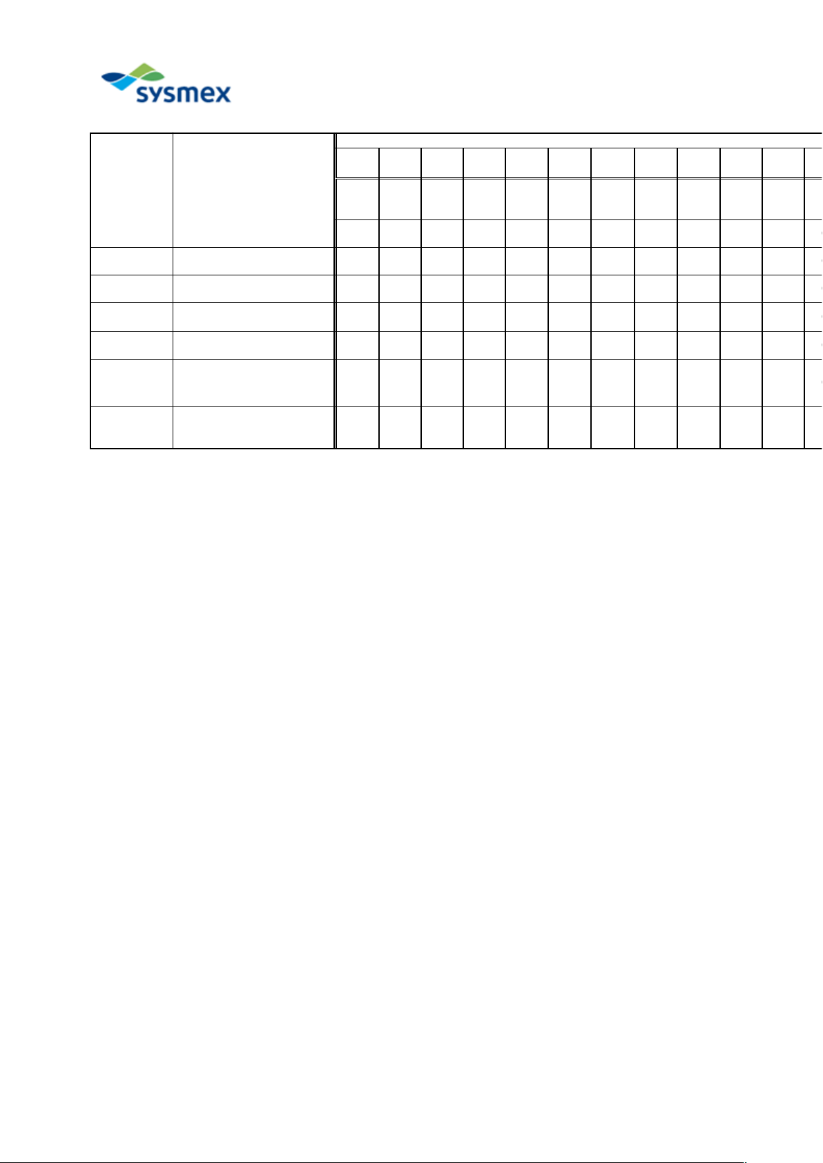
Part No. Part Name
Time for Replacement
0.5 yr1.0 yr1.5 yr2.0 yr2.5 yr3.0 yr3.5 yr4.0 yr4.5 yr5.0 yr5.5 yr6.0
yr
9k
cycle
18k
cycle
27k
cycle
36k
cycle
45k
cycle
54k
cycle
63k
cycle
72k
cycle
81k
cycle
90k
cycle
99k
cycle
108k
cycle
441-1634-7 PIPETTE NO.57 O O O O O O O O O O O O
442-3460-8 FITTING NO. 9A O O O O O O O O O O O O
442-5287-4 Silicone tube F739-8 O O O O O O
442-5789-9
TUBE PHARMED
1/4 IN X 1/8 IN
O O O O O O
443-1362-0 FILTER NO. 9 O O O
973-2984-2
KX-21 PNEUMATIC UNIT
(XP SERIES)
(PSL-21)
O O
963-3347-0
WASTE CHAMBER
NO.35 (C-7/XN SERIES)
(XN Series)
O
XP Series Periodic Replacement Parts List
“Time for Replacement” is only a guideline and differs according to status of use. Time-based or cycled-based
maintenance selection should be determined by whichever comes first.
Page 7
(Version 2)
Revision History
Version Number Date of Revision Revision Details
Version 1 April 27, 2012
Version 2 March 4, 2013 Added PCB NO.20034 to procedure for each adjustment
in "Other adjustments" section.
ECR 312J003
 Loading...