

Page 1

Automated Hematology Analyzer
XE-5000
Instructions for Use
CHAPTER 1 Introduction
CHAPTER 2 Safety Information
CHAPTER 3 Design and Function
CHAPTER 4 Reagents
CHAPTER 5 Before Using
CHAPTER 6 Operation
CHAPTER 7 Quality control
CHAPTER 8 Calibration
CHAPTER 9 Cleaning and Maintenance
CHAPTER 10 Troubleshooting
CHAPTER 11 Technical Information
CHAPTER 12 Warranty
CHAPTER 13 Index
SYSMEX CORPORATION
KOBE, JAPAN
Copyright © 2006 - 2008 by SYSMEX CORPORATION
All rights reserved. No part of this manual may be
reproduced in any form or by any means whatsoever
without prior written permission of SYSMEX CORPORATION.
Code No. 461-2642-1
PRINTED IN JAPAN
Date of Last Revision: December 2008
Page 2

Page 3

Table of Contents
Table of Contents
Chapter 1 Introduction .................................1-1
1.1 Hazard information in this manual............................1-3
1.2 Protected names ......................................................1-4
1.3 Measurement parameters ........................................1-4
Chapter 2 Safety Information....................... 2-1
2.1 Specified conditions of use........................... ... ... .... .. 2-1
2.2 General information..................................................2-1
2.3 Installation ................................................................2-2
2.4 Electromagnetic compatibility (EMC) .......................2-3
2.5 Avoidance of infection............................................... 2-3
2.6 Handling of reagents ................................................2-4
2.7 Quality control materials........................................... 2-5
2.8 Laser ........................................................................2-5
2.9 Maintaining the instrument....................................... 2-6
2.10 Disposal of waste fluids, disposables and
instruments...............................................................2-6
2.11 Marking on the instrument........................................2-7
2.12 Personnel ............................................................... 2-12
2.13 Computer viruses................................................... 2-12
Chapter 3 Design and Function ..................3-1
3.1 Overview................................................................... 3-1
3.2 Main Unit ..................................................................3-2
3.3 Pneumatic Unit....................................................... 3-11
3.4 Sampler Unit...........................................................3-13
3.5 Information Processing Unit (IPU).......................... 3-14
3.6 Analysis mode........................................................ 3-17
Chapter 4 Reagents......................................4-1
4.1 General information..................................................4-1
4.2 CELLPACK...............................................................4-1
4.3 CELLSHEATH ..........................................................4-1
4.4 STROMATOLYSER-FB.............................................4-2
4.5 STROMATOLYSER-4DL...........................................4-2
4.6 STROMATOLYSER-4DS ..........................................4-3
4.7 STROMATOLYSER-NR(L)........................................ 4-3
4.8 STROMATOLYSER-NR(S).......................................4-4
4.9 SULFOLYSER ..........................................................4-4
4.10 STROMATOLYSER-IM............................................. 4-5
4.11 RET SEARCH (II) (diluent)
RET SEARCH (II) (dye solution) ..............................4-5
4.12 CELLCLEAN ............................................................4-6
4.13 Control blood (e-CHECK(XE))..................................4-7
4.14 Labeling.................................................................... 4-7
4.15 Symbols used on the labels .....................................4-8
Revised July 2007 EU
Sysmex XE-5000 Instructions for Use I
Page 4

Table of Contents
Chapter 5 Before Using................................5-1
5.1 Storage prior to transport and installation ................5-1
5.2 Preparation...............................................................5-1
5.3 Peripherals................................................................5-2
5.4 Additional components .............................................5-2
5.5 Basic equipment settings..........................................5-3
Chapter 6 Operation..................................... 6-1
6.1 Summary of Main Unit operation..............................6-1
6.2 Main unit menu tree..................................................6-3
6.3 Summary of Information Processing Unit (IPU)
operation...................................................................6-4
6.4 Information Processing Unit (IPU) menu bar............6-5
6.5 Alarm sound .............................................................6-6
6.6 Operator checks .......................................................6-6
6.7 Turning ON the power...............................................6-8
6.8 Logging on to the Information Processing
Unit (IPU)................ ...... ....... ...... ....... ...... ....... ...... .....6-9
6.9 Self-checks...............................................................6-9
6.10 Pressure and vacuum gauges check......................6-11
6.11 Logging on the Main Unit............................... ...... ...6-11
6.12 Auto output settings check......................................6-11
6.13 Quality control.........................................................6-11
6.14 Conditions for sample analysis...............................6-12
6.15 Analysis mode .................................. ...... ....... ...... ...6-12
6.16 Preparing sample analysis .....................................6-13
6.17 Sample analysis in manual mode...........................6-17
6.18 Sample analysis in capillary mode .........................6-19
6.19 Sample analysis in sampler mode..........................6-21
6.20 Sample analysis in manual closed mode ...............6-24
6.21 Display analysis results ..........................................6-25
6.22 Analysis result output .................................... ...... ...6-26
6.23 HPC analysis..........................................................6-27
6.24 Body fluid analysis..................................................6-33
6.25 Timer processing....................................................6-38
6.26 Shutdown................................................................6-39
Chapter 7 Quality control.............................7-1
7.1 Quality control materials...........................................7-1
7.2 Quality control methods............................................7-1
7.3 Preparation...............................................................7-2
7.4 Quality control analysis.............................................7-5
7.5 QC data display........................................................7-7
7.6 Troubleshooting ......................................................7-12
7.7 Change lot ..............................................................7-13
7.8 Lot No.....................................................................7-13
7.9 Target/Limit.............................................................7-16
7.10 Display order...........................................................7-21
7.11 File Information....................................... ................7 -22
II Sysmex XE-5000 Instructions for Use
Revised April 2007
Page 5

Table of Contents
Chapter 8 Calibration...................................8-1
8.1 Calibration execution timing......................................8-1
8.2 Samples used for calibration ....................................8-1
8.3 Reference values...................................................... 8-1
8.4 Automatic calibration ................................................8-2
8.5 Displaying the last sample data................................ 8-6
8.6 Manual calibration .................................................... 8-6
8.7 Calibration history..................................................... 8-9
Chapter 9 Cleaning and Maintenance.........9-1
9.1 Execution of shutdown ............................................. 9-2
9.2 Removing fluid from the Pneumatic Unit
trap chamber ............................................................ 9-3
9.3 Cleaning the sample rotor valve............................... 9-4
9.4 Cleaning the manual rinse cup................................. 9-7
9.5 Cleaning the sample rotor valve tray........................ 9-9
9.6 Cleaning the piercer tray ........................................ 9-10
9.7 Removing clogs (clog removal sequence)..............9-11
9.8 Cleaning the IMI detector aperture.........................9-12
9.9 Cleaning the RBC detector aperture...................... 9-14
9.10 Removing air bubbles from the flow cell in the optical
detector block.........................................................9-17
9.11 Cleaning the flow cell in the optical
detector block.........................................................9-17
9.12 Replacing the waste container (option) ..................9-18
9.13 Replacing and registering reagents........................9-19
9.14 Reagent replacement log display function..............9-31
9.15 Remaining reagent volume function.......................9-36
9.16 Replacing the piercer ............................................. 9-38
9.17 Replacing the hand clipper..................................... 9-41
9.18 Replacing rubber plate No. 39................................ 9-43
9.19 Replacing the fuses................................................9-44
9.20 Replacing the HEPA filter (option).......................... 9-45
9.21 Adjusting pressure and vacuum.............................9-46
9.22 Supplies and replacement parts............................. 9-51
9.23 XE-5000 maintenanc e and ins pe cti on check list....9-5 2
Chapter 10 Troubleshooting........................10-1
10.1 HELP screen .......................................................... 10-1
10.2 Error log .... ...... ...... ....... ...... ..................................... 10-1
10.3 Error message list ..................................................10- 3
10.4 Troubleshooting guide ............................................10-9
10.5 Test....................................................................... 10-30
Revised April 2007 EU
Sysmex XE-5000 Instructions for Use III
Page 6

Table of Contents
Chapter 11 Technical Information............... 11-1
11.1 Performance/specifications of the XE-5000............11-1
11.2 Possible sample interferences................................11-9
11.3 Interface protocol..................................................11-10
11.4 Program version ...................................................11-10
11.5 Principles..............................................................11-11
11.6 Contents of the packages.....................................11-32
11.7 Check before installation ......................................11-36
11.8 Grounding.............................................................11-36
11.9 Installation environment............. ....... ...... ....... ...... .11-36
11.10 Installati on sp ace.................................... ....... ...... .11-37
Chapter 12 Warranty ....................................12-1
Chapter 13 Index .......................................... 13-1
IV Sysmex XE-5000 Instructions for Use
Revised April 2007
Page 7
1. Introduction
CHAPTER 1 Introduction
The Sysmex XE-5000 is an automated hematology analyzer
for in vitro diagnostic use in clinical laboratories.
The XE-5000 can analyze and output the results for 67
parameters.
WBCs, nucleated RBCs and reticulocytes are analyzed by the
optical detector block based on the fluorescence flow
cytometry method using semiconductor laser.
RBCs and platelet count are analyzed by the RBC detector
using the Hydro Dynamic Focusing method based on the
fluorescence flow cytometry method.
Hemoglobin (HGB) is analyzed by the HGB detector based on
the SLS hemoglobin determination method.
The existence of immature cells are analyzed by the IMI
detector based on the RF/DC detection method and the DIFF
channel using fluorescence flow cytometry.
Analysis data is displayed on the panel keypad LCD screen
and the screen of the Information Processing Unit (IPU).
Note:
Data generated by the XE-5000 is not intended to
replace professional judgment in the determination of
a diagnosis or in monitoring patient therapy.
Note:
Operate the instrument as instructed. Reliability of test
results cannot be guaranteed if there are any
deviations from the instructions in this manual. If the
instrument fails to function properly as a result of
either the user's operation not specified in the manual
or the user's utilization of a program not specified by
Sysmex, the product warranty would not apply.
Revised April 2007
Sysmex XE-5000 Instructions for Use 1-1
Page 8

CHAPTER 1 Introduction
Contact Address
Manufacturer
Authorized Representative
EC REP
Americas
SYSMEX CORPORATION
1-5-1 Wakinohama-Kaigandori
Chuo-ku, Kobe, Hyogo 651-0073
JAP AN
European Representative
SYSMEX EUROPE GmbH
Bornbarch 1
D – 22848 Norderstedt, Germany
Phone: +49 40 5 27 26-0
Fax: +49 40 5 27 26-100
SYSMEX AMERICA, Inc.
1 Nelson C. White Parkway,
Mundelein, IL 60060 U.S.A.
Phone: +1-847-996-4500
Fax: +1-847-996-4505
Asia-Pacific
SYSMEX ASIA PACIFIC PTE LTD.
2 Woodlands Sector 1,
#01-06 Woodlands Spec trum,
Singapore 738068
Phone: +65-6221-3629
Fax: +65-6221-3687
Ordering of Supplies and Replacement Parts
If you need to order supplies or replacement parts, please
contact your local Sysmex representative.
Service and Maintenance
Please contact the Service Department of local Sysmex
representative.
CE-mark
The IVD-system described in this manual is marked with a
CE-mark which confirms the observance of the essential
requirements of the following European directive:
98/79/EC IVD Directive
1-2 Sys mex XE-5000 Instructions for Use
Revised July 2007 EU
Page 9
1.1 Hazard information in this manual
Note, Information, Caution and Warning statements are
presented throughout this manual to call attention to
important safety and operational information. Non-compliance
with this information compromises the safety features
incorporated in the analyzer.
This symbol indicates a possible hazardous situation
which, if not avoided, may result in infection by
pathogens and others.
High risk. Ignoring this warning could result in
personal injury to the operator.
CHAPTER 1 Introduction
Risk of infection
Warning!
Caution, Hot!
Indicates a potential risk of burns or other physical
damage in the event of incorrect operation or failure to
observe the content.
Caution!
Ignoring this warning could result in property damage
or incorrect results. To avoid damage and incorrect
measuring results, this caution must be followed.
Information
Minor risk. Considerations that should be observed
when operating this instrument.
Caution!
Indicates a potential risk of physical damage to
functions of the instrument caused by static electricity
discharge of the human body, in the event of incorrect
operation or failure to observe the content.
Revised April 2007
Sysmex XE-5000 Instructions for Use 1-3
Page 10

CHAPTER 1 Introduction
1.2 Protected names
Note:
Background information and practical tips.
• Sysmex is a registered trademark of SYSMEX
CORPORATION.
• STROMATOLYSER, CELLPACK, SULFOLYSER, RET
SEARCH and CELLCLEAN are registered trademarks of
SYSMEX CORPORATION.
• CELLSHEATH is a trademark of Sysmex.
• SMI and SMI Micro/Pettor are registered trademarks of
Scientific Manufacturing Industries, Inc.
• VENOJECT and VENOJECT II are registered trademarks of
TERUMO Corporation.
• Windows is a registered trademark of Microsoft
Corporation.
Other trademarks referenced are property of their respective
owners.
TM and ® are not specified in this manual.
1.3 Measurement parameters
The XE-5000 can analyze the following 67 parameters:
37 Diagnostic Parameters
1WBC
2RBC
3HGB
4HCT
5MCV
6MCH
7 MCHC
8PLT
9RDW-SD
10 RDW-CV
11 PDW
12 MPV
13 P-LCR
14 PCT
15 NEUT%
16 LYMPH%
17 MONO%
18 EO%
19 BASO%
20 NEUT#
Revised April 2007
1-4 Sysmex XE-5000 Instructions for Use
Page 11

CHAPTER 1 Introduction
21 LYMPH#
22 MONO#
23 EO#
24 BASO#
25 IG% Immature Granulocyte Percent
26 IG# Immature Granulocyte Count
27 HPC# Hematopoietic Progenitor Cell Count
28 NRBC%
29 NRBC#
Note:
XE-5000 automatically analyzes NRBC if an analysis
order is assigned to any of the WBC 5 differential
counts or percent data.
30 RET%
31 RET#
32 HFR
33 MFR
34 LFR
35 IRF Immature Reticulocyte Fraction
36 RET-He Reticulocyte Hemoglobin Equivalent
37 IPF Immature PLT fraction
6 Body Fluid Mode Parameters
1 WBC-BF WBC body fluid
2MN% Mononuclear cell percent
3MN# Mononuclear cell count
4PMN% Polymorphonuclear cell percent
5PMN# Polymorphonuclear cell count
6 RBC-BF RBC body fluid
24 Pre-Diluted Mode Parameters
1WBC
2RBC
3HGB
4HCT
5MCV
6MCH
7 MCHC
8PLT
9NEUT%
10 LYMPH%
11 MONO%
12 EO%
13 BASO%
14 NEUT#
15 LYMPH#
16 MONO#
Revised April 2007 EU
17 EO#
Sysmex XE-5000 Instructions for Use 1-5
Page 12

CHAPTER 1 Introduction
18 BASO#
19 IG% Immature Granulocyte Percent
20 IG# Immature Granulocyte Count
21 NRBC%
22 NRBC#
23 RET%
24 RET#
1-6 Sysmex XE-5000 Instructions for Use
Revised April 2007 EU
Page 13
2. Safety Information
2.1 Specified conditions of use
The Sysmex XE-5000 is an automated hematology analyzer
for in vitro diagnostic use in clinical laboratories. Only human
blood, human body fluids or control blood should be run. Any
other use is regarded as non-specified.
Use only the reagents and rinse solutions mentioned in this
manual.
The specified conditions of use also entail the observance of
the cleaning and maintenance procedures described in these
instructions.
2.2 General information
Before operating this instrument, carefully read this manual,
and strictly follow its instructions.
Keep this manual for future reference after reading.
CHAPTER 2 Safety Information
Warning!
• Unpacking, installation, and confirmation of initial
operation must be done by Sysmex technical
representative.
• Keep your fingers, clothes and hair etc. away from
the instrument while it is in operation. There is a risk
of injury from becoming tangled or trapped in the
machinery.
• If the instrument emits an abnormal odor or smoke,
turn off the power switch immediately and disconnect
the power cord from the Main Unit. If the instrument
is used continuously in this condition, fire, electrical
shock or injury may result. Contact promptly your
Sysmex technical representative.
• Take care not to spill any fluids, or drop wire staples
or paper clips into the instrument. This might cause a
short circuit resulting in smoke emission. If such an
incident occurs, turn off the power switch
immediately and disconnect the power cord from the
Main Unit. Contact your Sysmex technical
representative.
• Do not remove the outer cover while the instrument
is in use. There is a risk of electrical shock or
instrument failure.
• Do not touch the electrical circuits inside the cover,
particularly if your hands are wet. Electrical shock
may result.
Revised April 2007
Sysmex XE-5000 Instructions for Use 2-1
Page 14
CHAPTER 2 Safety Information
2.3 Installation
Warning!
• Never put the power plug in any socket other than the
specified voltage. When installing the instrument, be
sure to ground it. Otherwise, fire or electrical shock
may result.
• Take care not to damage the power cord, not to
place a heavy device on it and not to pull it forcibly.
Otherwise, the wire may break causing fire or
electrical shock.
• When connecting the instrument to a peripheral
(host computers and printer etc.), be sure to turn off
the power switch beforehand. Otherwise, electrical
shock or instrument failure may result.
Caution!
• Install the instrument in a place which is not subject
to water splash.
• Install the instrument in a place which is not subject
to adverse effects of high temperature, high humidity,
dust, direct sunlight, etc.
• Do not give the instrument a strong vibration or
impact.
• Install in a well-ventilated area.
• Do not install near devices that cause signal noise,
such as radios and centrifugal machines.
• Do not install the instrument near a chemical storage
or a place where a gas is generated.
• Do not use this instrument in any operating
environment which has electro-conductive or
flammable gases, including oxygen, hydrogen and
anesthetic.
• This instrument was designed for indoor use only.
2-2 Sysmex XE-5000 Instructions for Use
Revised April 2007
Page 15

2.4 Electromagnetic compatibility (EMC)
This instrument complies with the following IEC (EN)
standards.
• IEC61326-2-6:2005 (EN61326-2 -6:200 5)
Electronic equipment for analysis, control and laborat ory
use — EMC request.
• EMI (electromagnetic emission (= interference radiation))
Class A requirements are fulfilled.
• EMS (electromagnetic immunity (= resistance against
jamming))
For this issue the minimum requirements with regards to
immunity are fulfilled.
2.5 Avoidance of infection
Risk of infection
• In principle, all parts and surfaces of the instrument
must be regarded as infective.
• Never touch waste or parts having been in contact
with waste, with bare hands.
• Should you inadvertently come in contact with
potentially infective materials or surfaces,
immediately rinse skin thoroughly with water, then
follow your laboratory’s prescribed cleaning and
decontamination procedures.
• Be careful when handling samples and control blood.
Use of personal protective equipment is strongly
recommended when operating, maintaini ng,
servicing or repairing the instrument.
• If patient samples of control material contact your
eyes, wash the area with plenty of water and
immediately contact a physician.
• Be careful when handling waste. If you get it on your
skin or clothes, wash with disinfectant.
CHAPTER 2 Safety Information
Revised April 2007
Sysmex XE-5000 Instructions for Use 2-3
Page 16
CHAPTER 2 Safety Information
2.6 Handling of reagents
Warning!
• Do not directly touch reagents. Reagents can cause
irritation of the eyes, skin and mucous membranes.
• Should you inadvertently come in contact with
reagent, immediately rinse skin thoroughly with
water.
• If a reagent should get in your eyes, immediately
rinse thoroughly with water and see a physician
immediately.
• If reagent is accidentally swallowed, follow
recommendations on Material Safety Dade Sheets
(MSDS) and see a physician immediately.
• CELLPACK diluent is electrically conductive. If
diluent is spilled inadvertently near electrical cables
or appliances, there is a risk of electrical shock.
Switch the instrument off, unplug it and remove the
liquid.
• CELLCLEAN is a strong alkaline detergent. It should
not come in contact with skin or clothing. If it
happens nevertheless, rinse skin or clothing with
plenty of water to avoid injury or damage.
• CELLCLEAN contains sodium hypochlorite. If
CELLCLEAN comes in contact with the instrument’s
surfaces, there may be a possibility of corrosion.
Immediately wipe up CELLCLEAN with a damp
cloth.
• Make sure the reagents used with the instruments
are kept level or below the Main Unit of the
instrument. Do not put reagents on top of the
instrument.
Caution!
• Follow directions on reagent containers.
• Avoid letting reagents come in contact with dust, dirt
or bacteria especially when installing new cubes.
• Reagents must not be used after their expiration
date.
• Handle reagents gently to avoid bubbling. Never
shake reagents. Do not use reagents immediately
after moving them.
• Take care not to spill reagents. If a reagent is spilled,
wipe up with a damp cloth.
2-4 Sys mex XE-5000 Instructions for Use
Revised July 2007
Page 17
2.7 Quality control materials
2.8 Laser
CHAPTER 2 Safety Information
Caution!
• Do not inject or ingest.
• Follow directions on control ma terial package insert.
• Av oid letting the control material come in contact with
dust, dirt or bacteria.
• Control material must not be used after their
expiration date.
• Take care not to spill control material. If spilled, follow
your laboratory's prescribed cleaning and
decontamination procedures.
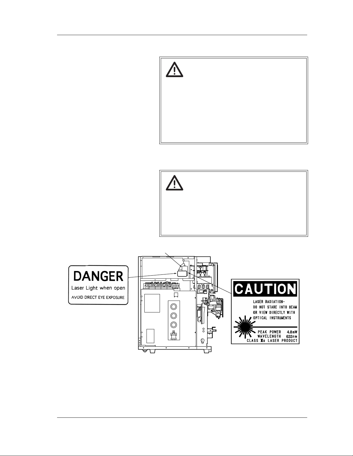
Warning!
The XE-5000 contains the semiconductor laser unit.
This semiconductor laser unit is shielded with the
shield box cover, and is provided with an interlock
system that prevents laser from oscillation if the cover
is removed. Do not open this cover. Otherwise, the
laser beam can damage your eyes.
Revised July 2007
Laser Diode
NOTE:This caution label is located
inside the Laser Unit Cover.
Sysmex XE-5000 Instructions for Use 2-5
Page 18
CHAPTER 2 Safety Information
2.9 Maintaining the instrument
Risk of infection
Always wear protective clothing, gloves and
eyeglasses when performing maintenance or
inspection to prevent contact with blood contaminated
parts. Wash your hands thoroughly following
maintenance.
Information
When performing maintenance, use only the tools
specially provided for such work. All cleaning and
maintenance procedures as described in this manual
must be observed for optimal performance.
2.10 Disposal of waste fluids, disposables and instruments
Risk of infection
Use of gloves is strongly recommended when
handling waste fluids or instrument consumables.
Wash your hands thoroughly following maintenance.
Warning!
Waste fluids, instrument consumables and other
waste materials must be disposed of appropriately in
accordance with local laws, with due consideration of
medical, infectious and industrial wastes.
2-6 Sysmex XE-5000 Instructions for Use
Revised April 2007
Page 19
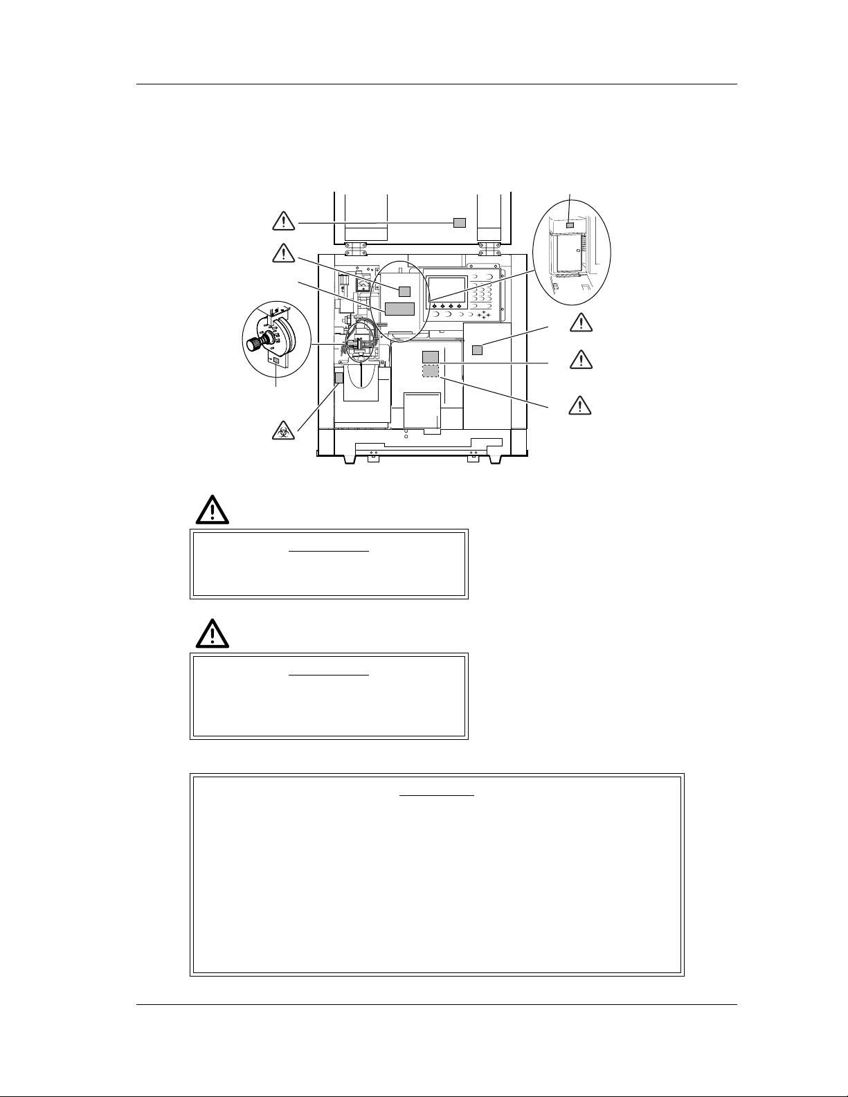
2.11 Marking on the instrument
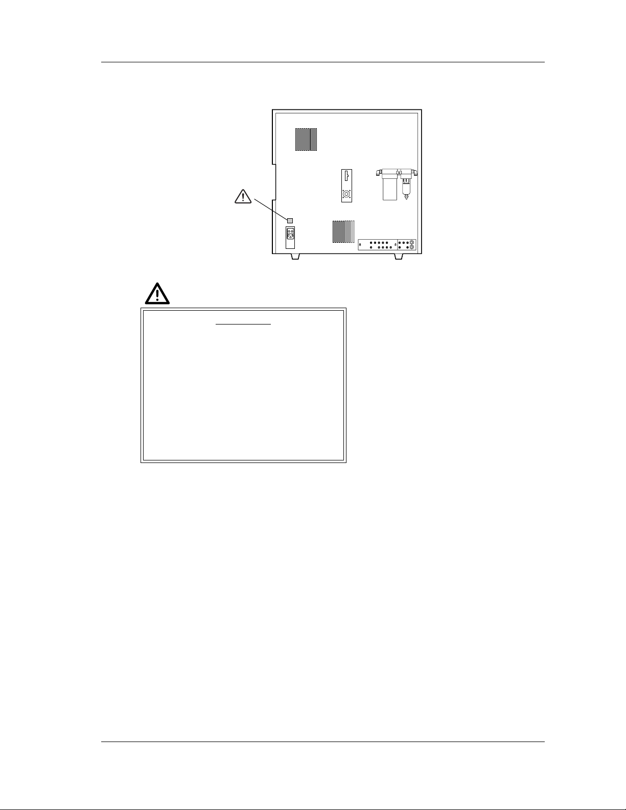
Main Unit - Front View
(1)
(2)
(3)
*1
(4)
(5)
CHAPTER 2 Safety Information
(6)
(7)
(8)
(9)
(Inside)
(1)
WARNING
Be sure to set the stop bar when opening
to avoid injury.
(2)
WARNING
Never touch the detector when the power
of the Main Unit is turned ON. Otherwise,
electrical shock may resu lt.
(3)
CAUTION
1. Dye solution replacement method
• For SNR, always replace dye solution and lyse reagent simultaneously.
• For RED, always replace dye solution and diluent simultaneously.
• For FFS, the message “Replace FFS” is displayed after the analysis of
2000 cycles. When doing so, always press Reagent or Confirm after
replacing with new FFS.
2. When the message “Execute Rinse Flowcell” is displayed, always perform
Maintenance – 4. Rinse Flowcell.
3. To clean the IMI detector aperture, first run Maintenance – 1. Drain IMI,
then turn off the main unit power.
Revised April 2007
Sysmex XE-5000 Instructions for Use 2-7
Page 20
CHAPTER 2 Safety Information
(4)
When installing this instrument, remove the constant-pressure screw, then
take out the anti-sticking spacers which are inserted between the sample rotor
valves. At that stage, rinse the surface of each valve cleanly before setting
them in place.
The fluid channel inside the instruments are rinsed with diluent before
shipping from the factory. Background count may be high immediately after
unpacking, so rinse thoroughly.
*1: After installing, remove the anti-sticking spacers.
(5)
RISK OF INFECTION
In principle, all parts and surfaces of the
instrument must be regarded as infective.
(6)
CAUTION
Always keep the switch in the analysis position.
(7)
WARNING
Never touch the detector when the power
of the Main Unit is turned ON. Otherwise,
electrical shock may resu lt.
(8)
WARNING
Do not remove this cover when the power
to the Main Unit is ON. Doing so may
result in injury.
(9)
WARNING
Do not put your fingers inside when the
power to the Main Unit is ON. Doing so
may result in injury.
2-8 Sysmex XE-5000 Instructions for Use
Revised April 2007
Page 21
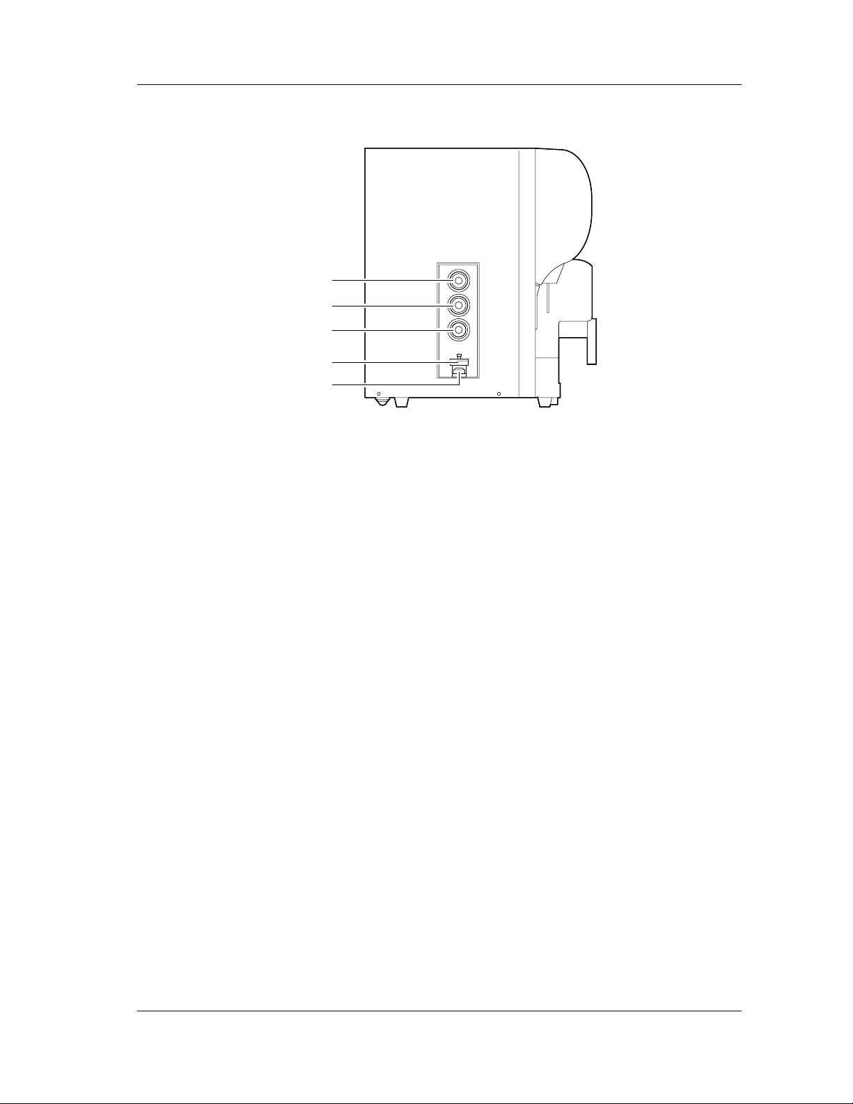
Main Unit - Rear View
(1)
• T o av oid electrical shock, disconnect
supply before servicing.
• For the continued protection
against risk of fire, replace only
with fuse of the specified type and
current ratings.
CHAPTER 2 Safety Information
(1)
CAUTION
Fuse Rating
3.15A 250V
Time Lag
Revised July 2007
Sysmex XE-5000 Instructions for Use 2-9
Page 22
CHAPTER 2 Safety Information
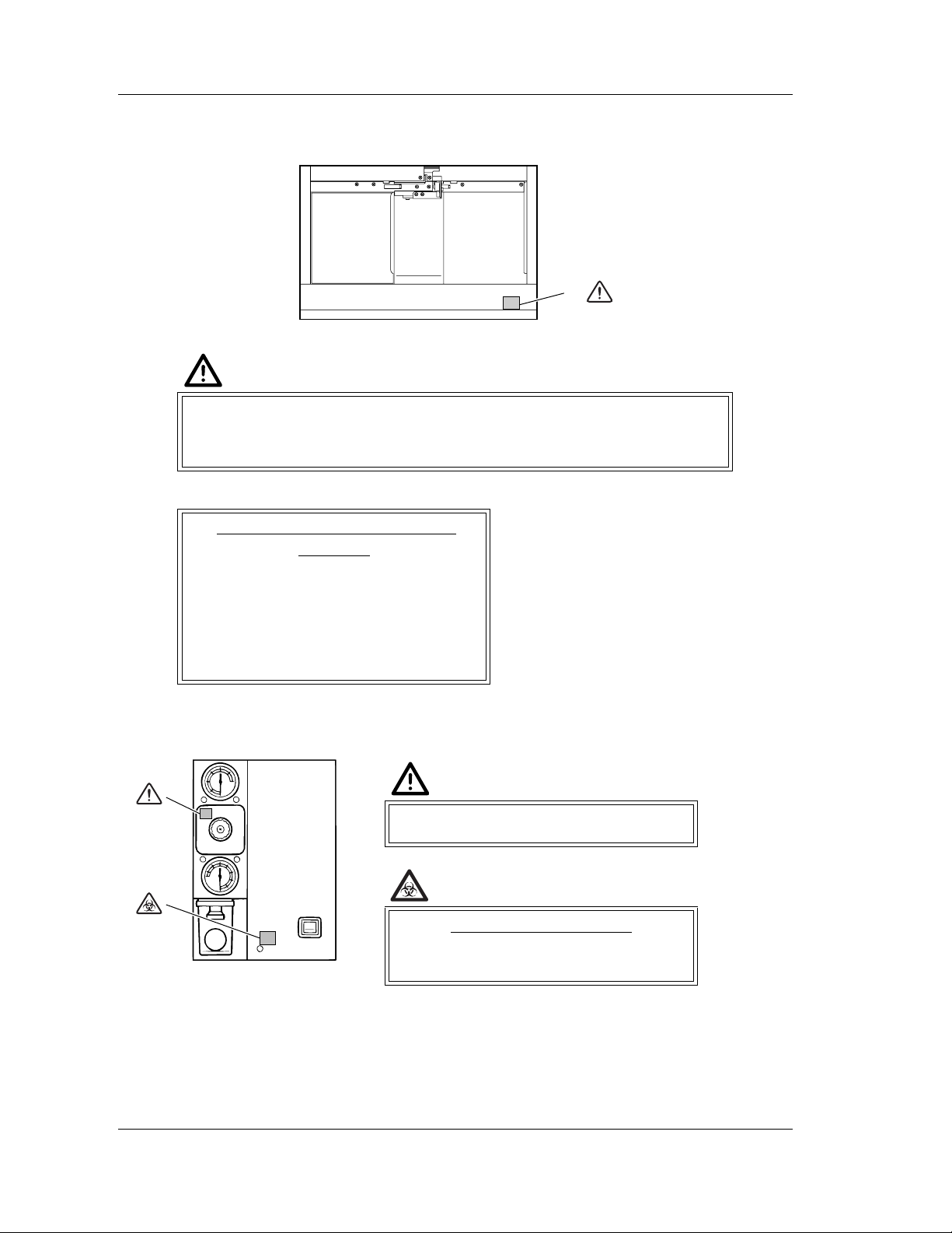
Sampler
(1)
Do not push in the rack by hand.
There is a small risk that such handling could cause a mismatch between
sample numbers and analysis results.
Precautions on setting the
sampler
1. Check that the sample tubes fit
smoothly into the rack.
2. Check that the rubber stoppers are
firmly capped on the sample tube.
3. Insert the sample tube securely all the
way to the bottom of the rack.
(1)
Pneumatic Unit - Front View
(1)
(1)
0.25 MPa regulator
(2)
(2)
RISK OF INFECTION
In principle, all parts and surfaces of the
instrument must be regarded as infective.
2-10 Sysmex XE-5000 Instructions for Use
Revised April 2007
Page 23
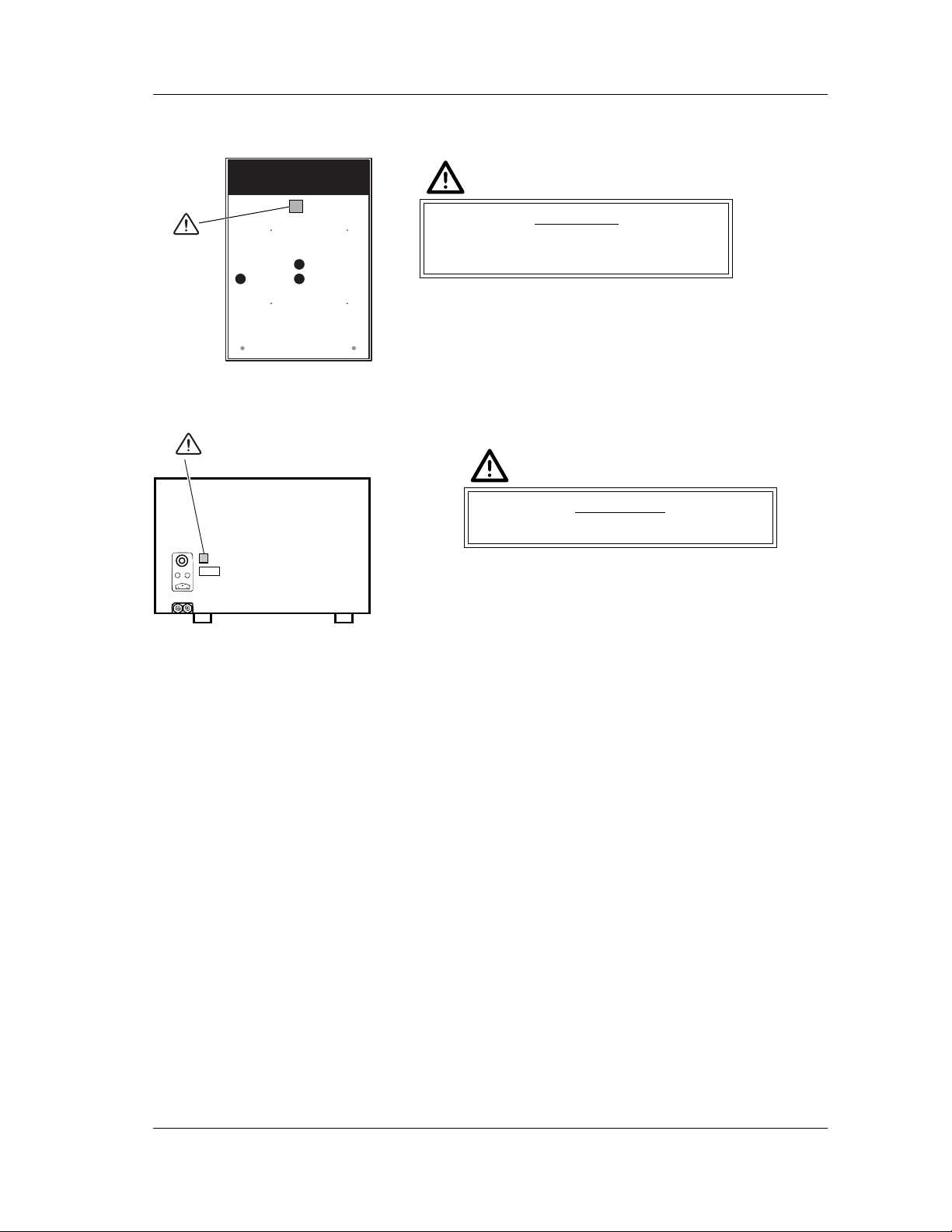
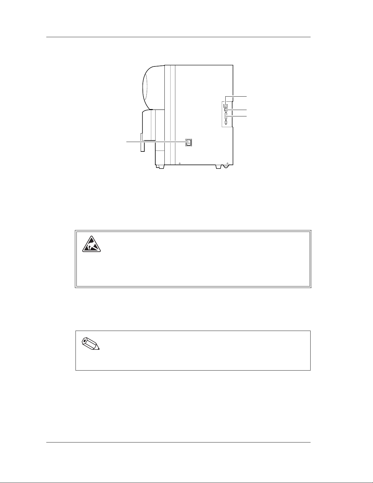
Pneumatic Unit - Rear View
CHAPTER 2 Safety Information
(1)
(1)
Pneumatic Unit - Right View
(1)
P
V
CAUTION
Do not block the exhaust vent on the rear
of the pneumatic unit.
(1)
WARNING
Instrument must be grounded.
Revised April 2007
Sysmex XE-5000 Instructions for Use 2-11
Page 24
CHAPTER 2 Safety Information
2.12 Personnel
2.13 Computer viruses
Caution!
• This instrument may only be operated by trained
personnel having been instructed in its operation.
• Only appropriately trained persons must perform
maintenance and repair work. Follow
troubleshooting instructions in the manual.
• Unpacking, installation, and confirmation of initial
operation must be done by Sysmex technical
representative.
Warning!
This system has been tested prior to shipment and is
virus free. But it may be infected with virus by
improper application on lines of Internet or network.
Please investigate and apply the corrective action for
computer virus approved by your facility.
Sysmex will not be held liable in the case that the
customer’s computer is infected with a virus and
therefore please take note of the following guidelines
in prior .
The following cases are just for your reference.
Please study the treatments according to the usage of
your computer.
1. Use a virus checker program regularly to check
your system.
2. Do not install any other application program except
a virus protection software.
3. Do not open any file attached to a mail from an
unknown address. Perform a virus check.
4. Do not download from Internet files not concerned
with Sysmex.
5. Files contained in a shared folder should be
subjected to a virus check.
6. Make sure to carry out any virus protection
measures currently used in other computer
systems.
2-12 Sysmex XE-5000 Instructions for Use
Revised April 2007
Page 25
CHAPTER 3 Design and Function
3. Design and Function
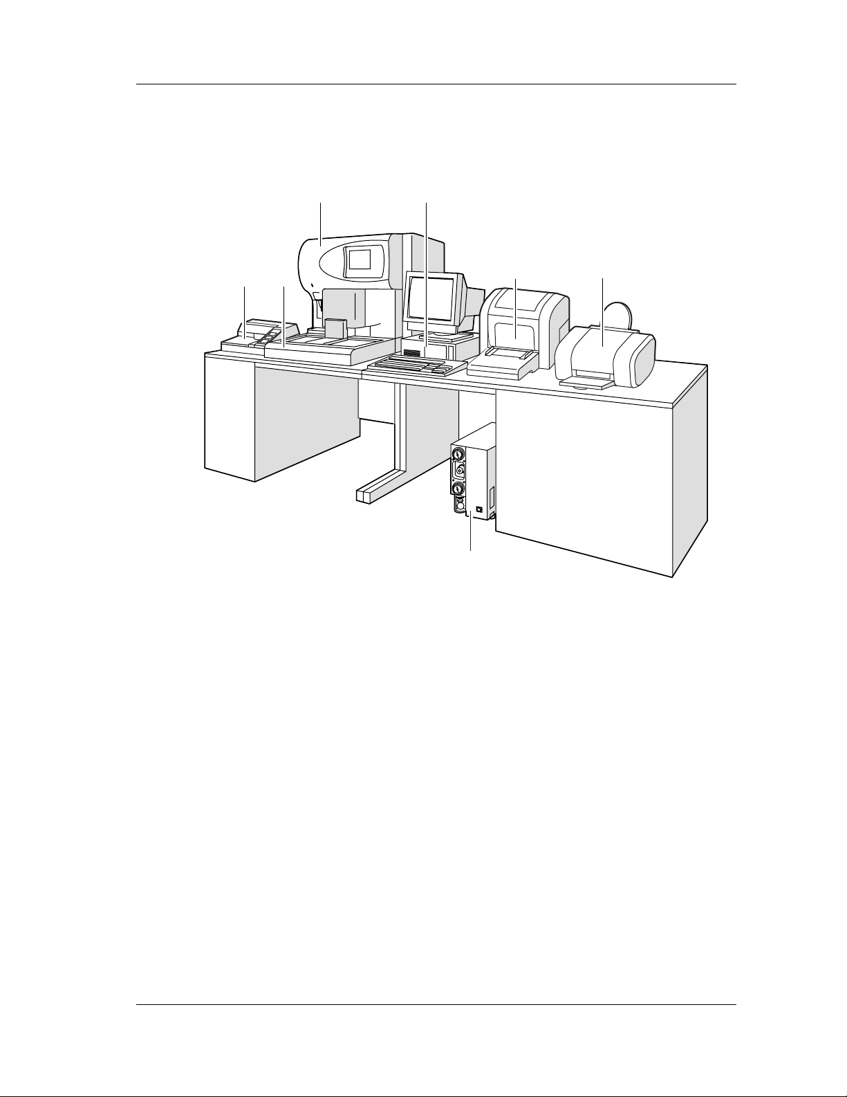
3.1 Overview
7 6
1
2
3
5
4
1Main Unit
Analyzes and controls samples.
2 Information Processing Unit (IPU)
Processes data which it receives from the Main Unit.
3 Ledger printer (option)
Prints lists of analysis information or results.
4 Color graphic printer (option)
Prints a hardcopy of analysis results or screen of histograms, scattergrams, etc.
5 Pneumatic unit
Supplies pressure and vacuum used by the Main Unit.
6 Sampler unit
Supplies samples to the Main Unit automatically.
7 Data printer (option)
Prints analysis data in the examination ticket format.
Revised April 2007
Sysmex XE-5000 Instructions for Use 3-1
Page 26
CHAPTER 3 Design and Function
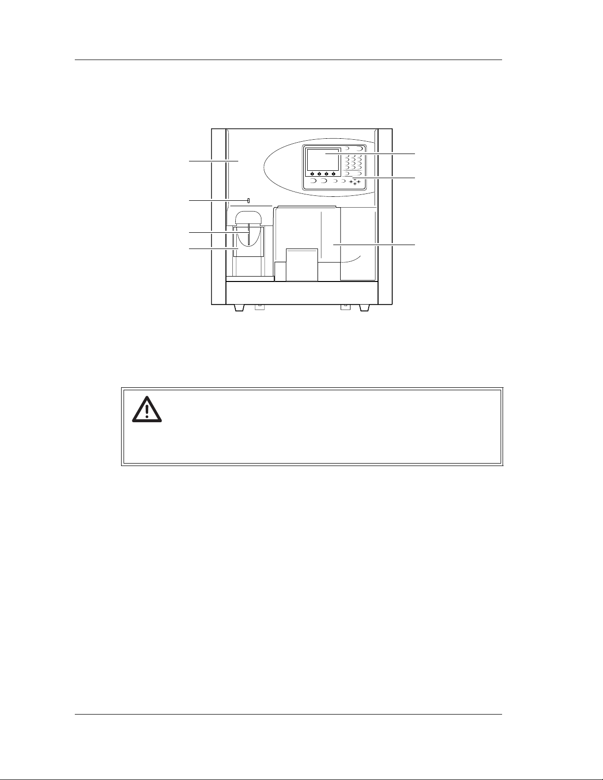
3.2 Main Unit
Front View
1
5
6
2
3
4
7
1 Front cover
Can be opened upward by hand. Open the cover to inspect or clean inside the Main
Unit.
Warning!
When inspecting inside the Main Unit with the front cover opened, be sure to set the
stop bar in advance.
Otherwise, the cover can drop down and injure your head.
2READY LED
Lights up when the Main Unit enters Ready status.
3 Manual aspiration pipette
Used to aspirate a sample in manual or capillary mode.
4 START switch
Used to start an analysis in manual, capillary or manual closed mode.
5 LCD screen
Displays the status of the Main Unit, sample ID number and analysis data.
6 Panel Keypad
Used to perform basic operation, such as inputting sample ID number, starting the
sampler analysis an d se lec ti ng th e an al ysis par a me te r. For details, see “Panel k eypad” .
7 CP cover
This is the protection cover of cap piercing unit.
3-2 Sysmex XE-5000 Instructions for Use
Revised April 2007
Page 27
CHAPTER 3 Design and Function
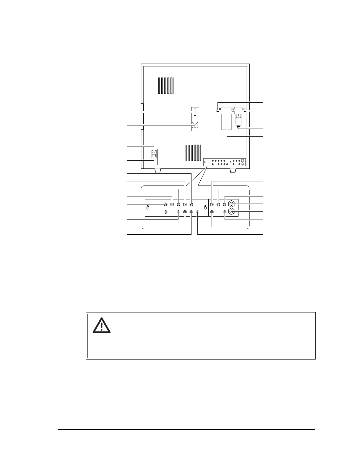
Rear View
1
14
15
2
16
17
3
4
5
6
7
8
9
10
11
12
18
19
20
21
22
23
24
13 25
1 Float switch connector
Connected to the float switch of each reagent.
2 Pneumatic Unit control output connector
Used as output connector for controlling ON/OFF of the Pneumatic Unit power.
Connected to the connector on the rear panel of the Pneumatic Unit.
3 Fuse holder
This is a 250V, 3.15A (time lag) fuse.
Warning!
• To avoid electrical shock, disconnect supply before servicing.
• For the continued protection against risk of fire, replace only with a fuse of the
specified type and current ratings.
4 AC power supply
Supplies power using the provided power cable.
5 ESE inlet nipple (ESE-1)
CELLSHEATH is aspirated via this nipple. Connected to the lower nipple of the
CELLSHEATH float switch.
Revised April 2007 EU
Sysmex XE-5000 Instructions for Use 3-3
Page 28

CHAPTER 3 Design and Function
6 SIM aspiration nipple (SIM-1)
STROMATOLYSER-IM is aspirated via this nipple. Connected to the lower nipple of the
STROMATOLYSER-IM float switch.
7 SLS inlet nipple (SLS)
SULFOLYSER is aspirated via this nipple. Connected to the container of
SULFOLYSER.
8 FFD reagent inlet nipple (FFD)
STROMATOLYSER-4DL is aspirated via this nipple. Connected to the container of
STROMATOLYSER-4DL.
9 FBA inlet nipple (FBA)
STROMATOLYSER-FB is aspirated via this nipple. Connected to the container of
STROMATOLYSER-FB.
10 SNR reagent inlet nipple (SNR)
STROMATOLYSER-NR (L) is aspirated via this nipple. Connected to the container of
STROMATOLYSER-NR (L).
11 RED diluent inlet nipple (RED)
RET SEARCH (II) diluent is aspirated via this nipple. Connected to the container of RET
SEARCH (II) diluent.
12 SIM air bubbles outlet nipple (SIM-2)
Air bubbles inside the float switch of STROMATOLYSER-IM are discharged via this
nipple. Connected to the upper nipple of the STROMATOLYSER-IM float switch.
13 ESE air bubbles outlet nipple (ESE-2)
Air bubbles inside the float switch of CELLSHEATH are discharged via this nipple.
Connected to the upper nipple of the CELLSHEATH float switch.
14 Air drier outlet nipple
Outputs pressure after removing dust or moisture by the air drier. Connected to the
pressure supply nipple.
15 Air drier inlet nipple
Connected to the pressure outlet nipple of the Pneumatic Unit.
16 Air drier drain nipple
Connected to the drain outlet nipple.
17 Air drier
Removes dust or moisture from the a ir (at PRESSURE sid e) supplied b y th e Pneumatic U nit.
18 EPK inlet nipple (EPK-1)
CELLPACK is aspirated via this nipple. Connected to the lower nipple of the CELLPACK
float switch.
19 Drain outlet nipple (D)
Water droplets from the air drier are discharged via this nipple to the waste line.
20 Vacuum supply nipple (V)
Connected to the vacuum outlet nipple of the Pneumatic Unit.
21 Waste level detection nipple (P2)
22 Waste level detection nipple (P1)
When the optional waste monitoring sensor is provided, the waste volume is monitored
by detecting differential pressure between the waste level detection nipples P1 and P2.
Connected to the detection tube of the waste container.
23 Pressure supply nipple (P)
Connected to the air drier outlet nipple.
24 Waste outlet nipple (W)
Waste fluid is discharged via this nipple. Connected to the sewer or the waste container.
25 EPK air bubbles outlet nipple (EPK-2)
Air bubbles inside the float switch of CELLPACK are discharged via this nipple.
Connected to the upper nipple of the CELLPACK float switch.
Revised April 2007 EU
3-4 Sysmex XE-5000 Instructions for Use
Page 29
CHAPTER 3 Design and Function
Left Side View
1
2
3
4
5
1 0.16 MPa regulator
Adjusts the pressure to 0.16 MPa.
2 0.07 MPa regulator
Adjusts the pressure to 0.07 MPa.
3 0.03 MPa regulator
Adjusts the pressure to 0.03 MPa.
4 Air filter
Prevents dust from entering the bellows unit.
5 Bellows Unit
Adjusts the bellows pressure to -0.04 MPa.
Revised April 2007
Sysmex XE-5000 Instructions for Use 3-5
Page 30
CHAPTER 3 Design and Function
Right Side View
4
1 Handheld barcode scanner connector
Connected to the optional handheld barcode scanner required to input sample ID
numbers.
2 IPU connector
The communication connector with the IPU. Connects to the connector of the IPU using
the provided cable.
1
2
3
Caution!
When connecting the communications cable (LAN cable) to the Information
Processing Unit (IPU), there is a risk of damage to communications equipment due
to static electrical charges on human body . Touch something else to discharge static
before connecting the cable.
3 DP connector
Connected to the data printer.
4 Power Supply Switch
Turns the power ON and OFF.
Note:
Do not turn the power ON and OFF repeatedly in a short period of time.
This can cause an overload to blow the fuse.
3-6 Sysmex XE-5000 Instructions for Use
Revised April 2007
Page 31

CHAPTER 3 Design and Function
Front Interior
1
2
8
3
4
9
5
6
7
10
11
1 RF tuning meter
Displays the status of radio-frequency voltage for the IMI detector.
2 Reaction chamber
Prepares a diluted sample for analyzing WBC/BASO, 4DIFF, NRBC and RET. The
sample is retained at a constant temperature for a certain period of time, and sent to the
optical detector block.
3 Blood aspiration sensor
Monitors the aspiration status of whole blood in the sampler mode or the manual closed
mode.
4 Sample rotor valve (SRV)
Measures the predetermined volume of the aspirated whole blood sample.
5 HGB detector block
Includes the HGB analyzer.
6 Whole blood aspiration pump
Aspirates a whole blood sample.
7 Whole blood aspiration motor
Drives the whole blood aspiration pump.
8 IMI detector block
Includes the IMI detector.
9 RBC detector block
Includes the RBC detector.
10 Sheath motor
Drives the sheath injector piston.
11 Sheath injector piston
Supplies a constant amount of diluted sample (1:500) to the RBC detector.
Revised April 2007
Sysmex XE-5000 Instructions for Use 3-7
Page 32

CHAPTER 3 Design and Function
Left Interior
1
2
3
1 WBC detector block
Includes the WBC detector.
2 Reaction chamber mixing motor
Mixes a diluted sample for analyzing WBC/BASO, 4DIFF, NRBC and RET.
3 Reaction chamber
Prepares a diluted sample for analyzing WBC/BASO, 4DIFF, NRBC and RET. The
sample is retained at a constant temperature for a certain period of time, and sent to the
optical detector block.
Caution!
Do not open the left cover unless the instruction is given by your Sysmex technical
representative.
Revised April 2007
3-8 Sysmex XE-5000 Instructions for Use
Page 33

CHAPTER 3 Design and Function
Panel keypad
12
13
SHUTDOWN HELP
NUM./ALPH. ENTER
RETURN MORE
9
MANUAL
7
GHI4JKL5MNO
PRS1TUV2WXY
QZ
0 -/. C
SAMPLER
ABC8DEF
9
6
3
8101112
No. Function
Used to enter the sample ID No . in manual mode , capil lary mode, HPC mod e, body fl uid mode
1
and manual closed mode. The sample ID No. setting screen is displayed. In additional to the
sample ID No., the discrete test profile and the analysis mode can be selected.
Used to start analysis in sampler mode.
2
When the sampler key is pressed, the sample ID No. setting screen is displayed, and you can
set sample ID No., rack No., and tube position from which the analysis has to start.
Used to specify sample ID No. and menu No.
3
Used to delete one character during key entry, or to stop the alarm.
4
Used to input hyphen [-] during sample ID No. entry, or decimal point during numeric entry.
5
Used to confirm the entered sample ID No.
6
Used to change input modes.
7
Used to change the LCD screen, or to move the selected parameter.
8
Used to change the function menu display on the screen which has five or more selectable
9
function menu items.
Used to cancel the execution of the menu and return to the status before selecting the menu.
10
In the presence of an error, pressing HELP will displa y the er ror messag e, probab le ca use and
11
corrective action to take.
Used to execute the shutdown sequence.
12
Used to select the function menu displayed at the bottom of the LCD screen.
13
3
4
5
6
7
Revised April 2007
Sysmex XE-5000 Instructions for Use 3-9
Page 34

CHAPTER 3 Design and Function
Panel Keypad LCD
1
2
3
4
5
6
7
8
9
10 10 10 10
1 Displays the mode to be used next.
There are the following four kinds of modes.
• Manual mode (Normal mode: Displayed as “Manual”)
(HPC analysis mode: Displayed as “HPC Manual”)
(Body fluid analysis mode: Displayed as “BF Manual”)
• Capillary mode (displayed as “Capillary”)
• Sampler mode (displayed as “Sampler”)
• Manual closed mode (displayed as “Closed”)
2 Displays the discrete setting for next analysis.
There are the following five kinds of discrete settings.
• CBC (displayed as “C”)
• CBC+NRBC (displayed as “C N” )
• CBC+RET (displayed as “C R”)
• CBC+DIFF+NRBC (displayed as “CDN”)
• CBC+DIFF+NRBC+RET (displayed as “CDNR”)
3 Displays the status of the Main Unit.
Any of the following status is displayed.
• Ready
• Not Ready
• Running
• S-Ready
•Stat
• S-Not Ready
4 Displays the manual sample ID No. to be analyzed next.
5 Displays the sample ID No. for DP printing.
6 Displays the present error content which has the highest priority.
When the error under the display is reset, the error with the next highest priority is
displayed.
If several errors occur, press the HELP key, and select Error List from the function
menu. All the errors are displayed.
3-10 Sysmex XE-5000 Instructions for Use
Revised April 2007 EU
Page 35

CHAPTER 3 Design and Function
7 Displays the input status by numeric keys.
Alphabet and hyphen in addition to numerals can be used for sample ID No.
By pressing the NUM./ALPH. key on the panel keypad, you can change the input mode
in this order: “Numeric” → “Uppercase Alphabet” → “Lowercase Alphabet”. The display
contents are as follows:
Num: Numeric mode
ALP: Uppercase Alphabet
alp: Lowercase Alphabet
8 Displays the status of the DP.
DP: DP is connected and no error has occurred.
No indication: DP is not connected.
DP (reversing display): DP is set to be connected, but an error has occurred.
9 Displays the implementation status of X
Xm: X
No indication: X
M QC is ON.
M QC is OFF.
10 Displays the function menu.
The contents of the function menu differ with each other.
3.3 Pneumatic Unit
Front View
M QC.
1
2
3
4
5
1 Pressure Indicator 1 (0.25 MPa)
Indicates pressure to be supplied to the Main Unit. The normal range is 0.25 ±
0.03 MPa. If pressure comes out of the normal range, the instrument may not operate
properly.
2 0.25 MPa regulator
Regulates the 0.25 MPa pressure to be supplied to the Main Unit.
3 Vacuum Indicator 2
Indicates vacuum to be supplied to the Main Unit. The normal range is -0.05 MPa or
over. If vacuum is less than -0.05 MPa, the instrument may not operate properly.
4 Pneumatic unit trap chamber
Prevents reagent, etc. from flowing into the compressor when an abnormality has
occurred in the instrument.
Revised April 2007
Sysmex XE-5000 Instructions for Use 3-11
Page 36

CHAPTER 3 Design and Function
5 Power supply switch
Turns the power ON and OFF.
Note:
Do not turn the power ON and OFF repeatedly in a short period of time.
This can cause an overload to blow the fuse.
Right Side View
1
2
3
4
5
1 Pneumatic Unit control input connector
The input connector for controlling the Pneumatic Unit ON/OFF. Connects to the
Pneumatic Unit control output connector of the Main Unit.
2 Fuse
This is a 250V, 3.15A (time lag) fuse.
Warning!
• To avoid electrical shock, disconnect supply before servicing.
• For the continued protection against risk of fire, replace only with fuse of the
specified type and current ratings.
3 Power supply connector
Supplies power with the power cord provided.
4 Vacuum outlet nipple
Supplies vacuum to the Main Unit. Connects to the vacuum supply nipple of the Main
Unit.
5 Pressure outlet nipple
Supplies pressure to the Main Unit. Connects to the air drier inlet nipple of the Main
Unit.
3-12 Sysmex XE-5000 Instructions for Use
Revised April 2007
Page 37

CHAPTER 3 Design and Function
3.4 Sampler Unit
1
3
2
4
1 Analysis line
A rack automatically shifts to the left once per cycle in an amount equivalent to one
sample. On this line, the ID is read and the sample is caught by the hand.
2 Left rack pool
The rack shifts from the analysis line to this pool.
3 Blood volume monitoring sensor
Monitors the volume of blood in the sample tube. If the volume is insufficient, the sample
cannot be analyzed.
4 Right rack pool
The racks are set in this pool. Up to 10 racks can be set at a time. Press the SAMPLER
key to feed the rack automatically to the analysis line.
Caution!
Do not manually push (or move) the sample rack forward while instrument is in
operation.
There is a small possibility that sample numbers and analysis results could become
misaligned.
Revised April 2007
Sysmex XE-5000 Instructions for Use 3-13
Page 38

CHAPTER 3 Design and Function
3.5 Information Proc essing Unit (IPU)
Front View
1
2
3
4
1 TFT display
SVGA compatible TFT multi-scan display.
2 Main body
IPU Main Unit of the personal computer.
3 Keyboard
Used to input data to the IPU.
4Mouse
Used to operate the various functions of the IPU.
Information
The IPU illustrations shown in this manual are for reference only. Refer to the
manual included with the computer for the layout of connection ports and other
details.
For further details, contact your Sysmex technical representative.
3-14 Sysmex XE-5000 Instructions for Use
Revised April 2007
Page 39

CHAPTER 3 Design and Function
Rear View
1
2
3
1 LP connector (LP: COM1)
Printer connector for printing out the ledgers.
2 GP connector (GP)
Printer connector for printing out the graphics.
3 Keyboard connector
Connector for the keyboard.
4 Main Unit connector (MAIN UNIT)
Connector for the XE-5000 Main Unit.
5 HOST connector (HOST: COM2)
Connector for the host computer.
6 Mouse connector
Connector for the mouse.
4
5
6
Revised April 2007
Sysmex XE-5000 Instructions for Use 3-15
Page 40

CHAPTER 3 Design and Function
Summary of the Information Processing Unit (IPU) display screen
1
2
3
4
5
6
1 Title bar
Displays the instrument name, display window name, No. of stored data, etc.
2 Menu bar
Displays the following:
• File • Report
• Edit • Settings
• View • Window
• Record • Help
• Action
There are submenus for each menu item. A pull down menu will be displayed when the
mouse is left clicked over the menu item.
Information
There may be some menu that cannot be selected, depending on the functions
currently effective.
Only menu items displayed in black may be selected.
3 Tool bar
The tool bar contains those pull down submenu items that are used comparatively often.
Double-click the icon on the tool bar will immediately execute that submenu action.
Inactive tool bar buttons are displayed in gray.
4Tab
The names of windows indicating menu icons are displayed.
When there are several windows, select a desired tab to change over the windows.
5 Window (View)
Operations are performed in these areas or windows.
3-16 Sysmex XE-5000 Instructions for Use
Revised April 2007
Page 41

CHAPTER 3 Design and Function
6 System status display area
The following status will be displayed:
• Main Unit status (Displays the status of up to 4 Main Units which can be connected to
one IPU).
• Host computer connection status
3.6 Analysis mode
Manual mode
In manual mode, the cap of the sample tube is manually removed and each sample is
aspirated individually via the whole blood aspiration pipette.
Capillary mode
In capillary mode, the sample diluted to 1:5 is aspirated manually via the whole blood
aspiration pipette, analyzed, displayed and reported.
Sampler mode
The sampler automatically mixes, aspirates and analyzes samples without removing their
caps. Up to 100 samples can be loaded at a time and analyzed automatically.
Manual closed mode
In manual closed mode, the sampler is used to aspirate the sample, without opening the cap
of the sample tube. This mode is basically the same as manual mode; mixing and
continuous analysis can not be performed automatically.
Note:
HPC analysis and body fluid analysis can only be performed in manual mode.
Revised April 2007
Sysmex XE-5000 Instructions for Use 3-17
Page 42

CHAPTER 3 Design and Function
Blank page
3-18 Sysmex XE-5000 Instructions for Use
Revised April 2007
Page 43

4. Reagents
4.1 General information
4.2 CELLPACK
Intended Use
CHAPTER 4 Reagents
All reagents used in this instrument are specialized reagents
for use in Sysmex instruments. Please do not use these
reagents for other purposes. Please follow the warnings for
handling and using each of the reagents correctly.
Note:
To ensure both customers safety and optimal system
performance, the manufacturer recommends that all
reagents boxes are placed at a level even with or
below the instrument base.
Diluent for use in hematology analyzers.
Storage and Shelf Life after first Opening
Usage
4.3 CELLSHEATH
Intended Use
Storage and Shelf Life after first Opening
Revised June 2008
Store CELLPACK at +5 to +30°C or lo wer temperature and
out of direct sunlight.
If once frozen, mix it well after thawing.
If the container is unopened, it may be use d up to the expiry
date stated on the reagent container.
Please refer to the product labeling (package insert or outer
package) for the open stability.
CELLPACK is a reagent f or me asuring the numbers and siz es
of RBC and platelets by the hydro dynamic focusing (DC
Detection). With the addition of the specified lyse reagent for
hemoglobin concentration determination, it can also be used
to analyze hemoglobin concentration.
Sheath fluid for use in hematology analyzers.
Store CELLSHEATH at +5 to +30ºC or lower temperature and
out of direct sunlight.
If once frozen, mix it well after thawing.
If the container is unopened, it may be use d up to the expiry
date stated on the reagent container.
Sysmex XE-5000 Instructions for Use 4-1
Page 44

CHAPTER 4 Reagents
Please refer to the product labeling (package insert or outer
package) for the open stability.
Usage
CELLSHEATH, in combination with the specified diluent, is a
reagent for analyzing the numbers and sizes of RBC and
platelets by the hydro dynamic focusing (DC Detection).
4.4 STROMATOLYSER-FB
Intended Use
A lyse reagent for the WBC/BASO channel of hematology
analyzers.
Storage and Shelf Life after first Opening
Store STROMATOLYSER-FB at +5 to +30°C or lower
temperature and out of direct sunlight.
If it freezes, mix it well after thawing.
If the container is unopened, it may be used up to the expiry
date stated on the reagent container.
Please refer to the product labeling (package insert or outer
package) for the open stability.
Usage
STROMATOLYSER-FB is a reagent for analyzing basophil
counts and WBC counts by the flow cytometry method, using
a semiconductor laser.
4.5 STROMATOLYSER-4DL
Intended Use
Diluent for the DIFF channel of hematology analyzers.
Storage and Shelf Life after first Opening
Store STROMATOLYSER-4DL at +2 to +35°C and out of
direct sunlight.
Do not use reagent that may have frozen.
If the container is unopened, it may be used up to the expiry
date stated on the reagent container.
Please refer to the product labeling (package insert or outer
package) for the open stability.
Usage
STROMATOLYSER-4DL is a reagent used in combination
with the specified dye solution (STROMATOLYSER-4DS) to
classify WBC by the flow cytometry method, using a
semiconductor laser.
4-2 Sysmex XE-5000 Instructions for Use
Revised April 2007
Page 45

4.6 STROMATOLYSER-4DS
Intended Use
Dye solution for the DIFF channel of hematology analyzers.
Storage and Shelf Life after first Opening
Store STROMATOLYSER-4DS in a dark place at +2 to +35°C.
Do not use reagent that may have frozen.
If the container is unopened, it may be used up to the expiry
date stated on the reagent container.
Please refer to the product labeling (package insert or outer
package) for the open stability.
Usage
STROMATOLYSER-4DS is a reagent used in combination
with the specified lyse reagent (STROMATOLYSER-4DL) to
classify WBC by the flow cytometry method, using a
semiconductor laser.
4.7 STROMATOLYSER-NR(L)
CHAPTER 4 Reagents
Intended Use
Lyse reagent for the NRBC channel of hematology analyzers.
Storage and Shelf Life after first Opening
Store STROMATOLYSER-NR(L) at +2 to +35°C and out of
direct sunlight.
Do not use reagent that may have frozen.
If the container is unopened, it may be used up to the expiry
date stated on the reagent container.
Please refer to the product labeling (package insert or outer
package) for the open stability.
Usage
STROMATOLYSER-NR(L) is a reagent using in combination
with STROMATOLYSER-NR(S) to analy ze er y thr oblast co unt
and ratio by the flow cytometry method, using a
semiconductor laser.
Revised April 2007 EU
Sysmex XE-5000 Instructions for Use 4-3
Page 46

CHAPTER 4 Reagents
4.8 STROMATOLYSER-NR(S)
Intended Use
Dye solution for the NRBC channel of hematology analyzers.
Storage and Shelf Life after first Opening
Store STROMATOLYSER-NR(S) at +2 to +35°C and out of
direct sunlight.
Do not use reagent that may have frozen.
If the container is unopened, it may be used up to the expiry
date stated on the reagent container.
Please refer to the product labeling (package insert or outer
package) for the open stability.
Usage
STROMATOLYSER-NR(S) is a reagent using in combination
with STROMATOLYSER-NR(L) to analyze erythroblast count
and ratio by the flow cytometry method, using a
semiconductor laser.
4.9 SULFOLYSER
Intended Use
A cyanide-free lyse reagent for the hemoglobin determination
in hematology analyzers.
Storage and Shelf Life after first Opening
Store SULFOLYSER at +1 to +30°C and out of direct sunlight.
If it has frozen, thaw it in warm water at 30°C or below, and
mix it thoroughly before use.
If the container is unopened, it may be used up to the expiry
date stated on the reagent container.
Please refer to the product labeling (package insert or outer
package) for the open stability.
Usage
SULFOLYSER is a reagent used in combination with the
specified diluent to analyze the hemoglobin concentration
dissolved out of RBCs by the SLS-hemoglobin method.
4-4 Sysmex XE-5000 Instructions for Use
Revised April 2007 EU
Page 47

4.10 STROMATOLYSER-IM
Intended Use
A lyse reagent for the IMI channel of hematology analyzers.
Storage and Shelf Life after first Opening
Store STROMATOLYSER-IM at +2 to +35°C or lower
temperature and out of direct sunlight.
If it freezes, mix it well after thawing.
If the container is unopened, it may be used up to the expiry
date stated on the reagent container.
Please refer to the product labeling (package insert or outer
package) for the open stability.
Usage
STROMATOLYSER-IM is a reagent for detecting immature
cells by the RF/DC detection method.
4.11 RET SEARCH (II) (diluent) RET SEARCH (II) (dye solution)
CHAPTER 4 Reagents
Intended Use
Lyse reagent and dye solution for the RET channel of
hematology analyzers.
Storage and Shelf Life after first Opening
Store RET SEARCH (II) in a dark place at +2 to +35°C.
Do not use reagent that may have frozen.
If the container is unopened, it may be used up to the expiry
date stated on the reagent container.
Please refer to the product labeling (package insert or outer
package) for the open stability.
Usage
RET SEARCH (II) is a reagent using in the combination of
RET SEARCH (II) (diluent) and RET SEARCH (II) (dye
solution) to analyze reticuloc yte s and opti c ally ana ly zed
platelets by the flow cytometry method, using a
semiconductor laser.
Revised April 2007 EU
Sysmex XE-5000 Instructions for Use 4-5
Page 48

CHAPTER 4 Reagents
4.12 CELLCLEAN
Intended Use
CELLCLEAN is a strong alkaline detergent to remove lyse
reagents, cellular residuals and blood proteins remaining in
the hydraulics of Sysmex automated hematology analyzers.
Warnings and Precautions
Storage and Shelf Life after first Opening
Store CELLCLEAN in a dark place at +15 to +30°C.
Avoid e xposing direct sunlight, or the chlorine component may
deform and lose its effectiveness, depending upon the period
of exposure.
Warning!
1. Avoid contact with skin and eyes.
2. In case of skin contact, flush the area with water.
3. In case of contact with eyes, rinse immediately with
plenty of water and seek medical advice.
4. If accidentally swallowed, seek medical advice
immediately.
Usage
CELLCLEAN is a detergent to clean and remove cellular
residuals and blood proteins from the hydraulic systems,
detector, whole blood aspiration line tube and other parts in
the blood cell analysis instrument.
4-6 Sysmex XE-5000 Instructions for Use
Revised April 2007 EU
Page 49

4.13 Control blood (e-CHECK(XE))
Intended Use
e-CHECK(XE) is a hematology control material primarily for
intralaboratory quality control of automated, semiautomated
and manual procedures that measure components of blood.
Additionally, e-CHECK(XE) can be used in external quality
assessment.
Warnings and Precautions
CHAPTER 4 Reagents
Risk of infection
When using control blood, use personal protective
equipment. After completion of the analysis, be sure to
wash your hands with disinfectant.
Warning!
Potentially Infectious Material-All human source
material used to manufacture this product was nonreactive for antigens to Hepatitis B9(HbsAg), negative
by tests for antibodies to HIV(HIV-1/HIV-2) and
Hepatitis C9(HCV), non-reactive for HIR-1 RNA and
HCV RNA by licensed NAT, and non-reactive to
Serological Test for Syphilis(STS) using techniques
specified by the U.S Food and Drug Administration.
Because no known test method can assure complete
absence of human pathogens, this product should be
handled with appropriate precautions.
Storage and Shelf Life after first Opening
Store control material as per product insert at +2 to +8°C.
If unopened, e-CHECK(XE) may be used up to the expiration
date shown on the container. Once opened, it should be used
within 14 days.
4.14 Labeling
Important information about the handling of reagents and
quality control material is noted on the package insert and
containers. Please read the labels and package insert prior to
use.
Revised April 2007 EU
Sysmex XE-5000 Instructions for Use 4-7
Page 50

CHAPTER 4 Reagents
4.15 Sym bols used on the labels
IVD
LOT 1234
22-Nov-2000
+NN C
-NN C
Xn
In Vitro Diagnostic
Consult instructions for use
Lot-number
Use by
Storage temperature
CE conformity sign as per directive
98/79/EC
Hazardous Class in EU
Manufacturer
EC REP
Authorized representative in
the European community
Revised April 2007 EU
4-8 Sysmex XE-5000 Instructions for Use
Page 51

5. Before Using
5.1 Storage prior to transport and installation
• Once the instrument is delivered, check the condition of its
packaging as soon as possible.
Information
If the packaging has been damaged in any way,
contact your Sysmex technical representative as soon
as possib le.
• Store the instrument as packaged in a dry place until
installation. Do not turn it over or store it upside down.
Information
A Sysmex technical representative will perform the
initial setup of this instrument. Thereafter, if you wish
to move it to another location, please contact your
Sysmex technical representative.
CHAPTER 5 Before Using
5.2 Preparation
• Install the XE-5000 in a dry and dust-free environment.
• It should be located in a space large enough to be used
safely. If additional equipment is to be connected to it,
further desk space will be required.
• The instrument weighs approximately 93 kg. Be sure to use
a table or desk that can support that amount of weight.
• Leave a space of 50 cm or more between the walls and the
side, rear and top panels to allow for heat dissipation. Also,
leave enough space when installing for maintenance and
service work to be performed.
• Do not install this equipment near any devices that emit
high-frequency signals or noise (radios, centrifuges, etc.).
• The power cable for this instrument is 1.8 m long. Use a
nearby outlet that is designed for it.
Revised April 2007
Sysmex XE-5000 Instructions for Use 5-1
Page 52

CHAPTER 5 Before Using
5.3 Peripherals
Caution!
• Turn the power switch of the instrument OFF before
connecting peripherals.
• Each peripheral device that is connected will need its
own power outlet. Do not plug multiple devices into
extensions and adaptors. Such wiring could cause
fire.
Ledger printer (option)
Color graphic printer (option)
Data printer (option)
(For the functions of the printers, see “Chapter 3: 3.1
Overview”).
Note:
The ledger printer, color graphic printer and data
printer are optional.
Refer to the corresponding printer manuals for details
of their installation.
5.4 Additional components
Handheld barcode scanner (option)
A handheld barcode scanner scans the barcode on the
sample tube and automatically inputs the sample number.
Note:
The handheld barcode scanner is optional.
Refer to the handheld barcode scanner manuals for
the connection method.
Waste sensor unit (option)
Informs the operator that the waste container is full.
Note:
The waste sensor unit is optional.
Revised April 2007
5-2 Sysmex XE-5000 Instructions for Use
Page 53

Uninterruptible power suppl y (UPS) (option)
A backup power supply which allows the IPU to operate for a
maximum of 5 minutes in the event of power failure. In case of
momentary power interruption caused by a thunder storm, the
UPS protects the IPU hard disk.
5.5 Basic equipment settings
CHAPTER 5 Before Using
Note:
The uninterruptible power supply (UPS) is optional.
Note:
This chapter only explains the settings rela ted to the
initial operations. For more detailed information about
other settings, see “Chapter 5: Instrument Setup” in
the Software Guide.
Date and Time
Set the date and time accurately , using the Windows date and
time adjustment function on the Information Processing Unit
(IPU).
Information
The date and time cannot be set from the XE-5000
setup program.
Brightness adjustment of panel keypad LCD screen
1. Open the front cover of the Main Unit.
89
7
5
4
23
1
0%
6
C
2. The LCD brightness can be adjusted using the brightness
adjustment volume under the panel keypad.
Turn to the right: Darker
Turn to the left: Lighter
3. Close the front cover of the Main Unit.
Brightness
adjustment
volume
Darker Lighter
Revised April 2007
Sysmex XE-5000 Instructions for Use 5-3
Page 54

CHAPTER 5 Before Using
Blank page
5-4 Sysmex XE-5000 Instructions for Use
Revised April 2007
Page 55

6. Operation
6.1 Summary of Main Unit operation
Various functions can be activated by selecting them from
menus on the panel keypad of the Main Unit.
On the LCD screen, the functions that are usable from each
menu are displayed on submenu. Information such as the
status of the instrument and the setting status of the next
sample to be analyzed is displayed at the top of the screen.
Main Menu
Manual
C D N R
Ready
POS ERR
RBC 3.41 x10^6/uL
HGB 9.9 g/dL
HCT 31.3 %
MCV 91.8 fL
MCH 29.0 pg
MCHC 31.6 g/dL
PLT 191 x10^3/uL
RET% 38.7 %
RET# 0.1320 x10^6/uL
NRBC 1.29 x10^3/uL
QC AutoRinse Maint Reagent
Next No.123456789012346
DP No. 123456789012345
PNo. 123456789012345 123456-01
WBC & 14.08 x10^3/uL
NEUT 10.37 73.6 %
LYMPH 2.19 15.6 %
MONO 1.38 9.8 %
EO 0.03 0.2 %
BASO 0.11 0.8 %
IG 0.05 0.6 %
HPC x10^3/uL
Num
DP
Xm
The function menu of the main menu is displayed on the
bottom of the main menu screen.
• If there are five or more function menus, press the MORE
key to display the remaining function menus.
• To select a function menu, press the corresponding
selection key below the LCD screen.
• To return to the main menu screen from another screen,
press the RETURN key.
CHAPTER 6 Operation
MANUAL
7
0 -/. C
NUM./ALPH. ENTER
SHUTDOWN HELP
RETURN MORE
Submenu selection
SAMPLER
ABC8DEF
9
GHI4JKL5MNO
6
PRS1TUV2WXY
3
QZ
Note:
To return to the main menu screen, depending on the
currently displayed screen, it may be necessary to
press the RETURN key several times.
When an item on the main menu is selected, the submenu
available for that item is displayed.
The following methods can be selected, depending on the
submenu.
• When using a submenu of the function menu, press the
corresponding selection key below the LCD screen.
• If there is a submenu with a menu number, press the
number key for that menu number, or use the cursor keys to
select the menu.
Revised April 2007
Sysmex XE-5000 Instructions for Use 6-1
Page 56

CHAPTER 6 Operation
Entering numbers and characters
Sample numbers or the like can be entered from the panel
keypad.
By pressing the NUM./ALPH. key on the panel keypad, you
can change the input mode in this order: “Numeric” →
“Uppercase Alphabet” → “Lowercase Alphabet”.
• Press the corresponding number keys to enter numbers.
• To enter characters, press the corresponding number key
repeatedly until the intended character appears.
• Press the C key to delete a character.
• Press the ENTER key to confirm input.
6-2 Sysmex XE-5000 Instructions for Use
Revised April 2007
Page 57

6.2 Main unit menu tree
CHAPTER 6 Operation
QC*
AutoRinse
Mainte.
Reagent
Logoff
Cal 1. Manual
Test
Exec. QC
Xm STT/STP
Status
Sampler
1. Drain IMI
2. Air Bubble Removal
3. Clog Removal
4. Rinse Flowcell
5. Drain Waste
2. HGB/HCT
1. Sensor 1
2. Sensor 2
3. Counter
4. Pump
1. Rack Feed In
2. Rack Shift
3. Rack Feed Out
CP
Barcode
Motor
SRV
Replenish
1. WB. Asp. Motor
2. RBC Sheath Injector
3. FCM Sheath Injector
4. Spits Motor
5. Mixing Motor
1. FFD
2. FFS
3. SNR
4. RED
5. FBA
6. EPK
7. ESE
8. SLS
9. SIM
* : “B-Check” will be displayed instead of “QC” in the body fluid mode.
“B-Check” means background check.
Revised June 2008
Sysmex XE-5000 Instructions for Use 6-3
Page 58

CHAPTER 6 Operation
6.3 Summary of Information Processing Unit (IPU) operation
Caution!
• The Information Processing Unit (IPU) is to be used
exclusively with the XE-5000 and can not be used as
a regular computer.
• Operation not covered in this manual or use of
programs not specified by Sysmex renders the
warranty invalid and may cause the Information
Processing Unit (IPU) to perform incorrectly.
Menu screen
The menu screen appears after the Information Processing
Unit (IPU) is turned on and the user logs in to the application
program.
Note:
The menu screen is customizable. Therefore, the
screen displays presented in this manual may differ
from the actual screen displays on the instrument.
For details of screen customization, see “Chapter 5:
Instrument Setup” in the Software Guide.
Menu selection
The following three methods may be used to select an item on
the menu.
• Double-click the icon on the tool bar.
• Click on the menu, then select the submenu item from the
pull down.
• Double-click the icon on the menu screen.
6-4 Sysmex XE-5000 Instructions for Use
Revised April 2007
Page 59

Dialog box
The dialog box is displayed when a specified menu or
command button is selected.
6.4 Information Processing Unit (IPU) menu bar
Menu Submenu Menu Function
File Open
Close
Save
Print
Log Off
Exit
Edit Select All
Find
Property
View Toolbar
Status Bar
Menu
QC
Work List
Sample Explorer
Data Browser
Record Sort
Filter
Auto Add
Manual Add
Delete
Backup
Restore
Download
First
Upper
Lower
Last
Output (CSV format)
Action Validate
Pending List
Last20
Report Host (HC)
Ticket (DP)
Report (GP)
Ledger (LP)
Report for Lab. Use Only
Opens the data browser (only when the sample explorer is running).
Closes the window.
Overwrites and save the presently selected item record.
Prints the screen.
Logs off (To the logoff screen.)
Quits the application. (To the quit confirmation screen.)
Selects all records.
Displays the se arch win dow.
Changes the tab title.
Displays or close the tool bar.
Displays or close the sta tus bar.
Starts Menu.
Starts QC.
Starts Work List.
Starts Sample Explorer.
Starts Data Browser.
Realigns the displayed patient records. (To sort condition input dialog
box.)
Selects displayed patient record. (To filter condition input dialog box.)
Adds new records.
Adds new records.
Deletes selected record.
Backs up selected record to the hard disk or USB device.
Lists up information saved to the hard disk or USB device.
Downloads from the host computer.
Moves to the top record.
Moves to the previous record.
Moves to the next record.
Moves to the last rec ord.
Outputs the selected data as a file in CSV format.
Validates the displayed sample.
Displays the pen din g work list.
Displays the lat e st 20 samp les.
Transfers the selected analysis results to the host computer (HC).
Prints the selected analysis results on a ticket printer (DP).
Prints th e selected analysis results on a report printer (GP).
Prints th e selected analysis resul ts on a ledger printer (LP).
Prints the selected analysis results on a report printer (GP) with
laboratory-use-only format.
CHAPTER 6 Operation
Revised April 2007
Sysmex XE-5000 Instructions for Use 6-5
Page 60

CHAPTER 6 Operation
Menu Submenu Menu Function
Setting Date Format
Auto Validate
Auto Output
Discrete
Analysis Ordering
User Administration
Host (HC) Setting
Report (GP) Setting
Ledger (LP) Setting
Categories
Reference Interval
Units
Reference Lim it
CSV Output Setting
Backup
Window Cascade
Tile
Split
Help About XE-5000 Displays the application version. (To version display dialog box.)
Starts Setting/System.
Starts Setting/Auto Validate.
Starts Setting/Auto Output.
Starts Setting/Discrete.
Starts Setting/Analysis Ordering.
Starts Setting/User Administration.
Starts Setting/Host (HC) Setting.
Starts Setting/Report (GP) Setting.
Starts Setting/Ledger (LP) Setting.
Starts Setting/Categories.
Starts Setting/Reference Interval .
Starts Setting/Item Attributes.
Starts Setting/Sampler Stop Limit Setting.
Starts Setting/CSV Output Setting.
Starts Setting/Backup.
Displays the pres en tly disp layed windows casc ade styl e.
Displays par al le ls in above and below, left and right.
Splits window display.
6.5 Alarm sound
6.6 Operator checks
1. Reagent check
In the XE-5000, three types of alarm sounds are used to alert
the operator:
Key Entry Alarm (single beep)
Sounds about 0.1 second when a key is pressed on the panel
keypad.
Input Error Alarm (short beep)
Sounds about 1 second when a wrong key is pressed on the
panel keypad.
Analysis Error Alarm (long beep)
Sounds when an error occurs in the Main Unit and continues
until the C key or HELP key is pressed on the panel keypad.
Make sure that there is a sufficient amount of reagent for the
day’s samples. If the amount is insufficient, prepare
replacement reagent. If reagent runs out during an analysis,
the system automatically stops and alerts the operator to
replace the insufficient reagent. Analysis cannot be restarted
until replacement is completed. The following shows the
approximate number of cycles that can be analyzed per
container of reagent.
6-6 Sysmex XE-5000 Instructions for Use
Revised April 2007
Page 61

CHAPTER 6 Operation
●Samples Analyzed per Reagent Container
Reagent Abbreviation
CELLPACK EPK Approx. 660
CELLSHEATH ESE Approx. 7300
STROMATOLYSER-FBFBA Approx. 2750
STROMATOLYSER4DL
STROMATOLYSER4DS
STROMATOLYSERNR(L)
STROMATOLYSERNR(S)
SULFOLYSER SLS Approx. 10000
STROMATOLYSER-IMSIM Approx. 3200
RET SEARCH (II)
(Diluent)
RET SEARCH (II)
(Dye solution)
FFD Approx. 2750
FFS Approx. 2000
SNR Approx. 2000
RED Approx. 550
No. of cycles/
container
cycles
cycles
cycles
cycles
cycles
cycles
Approx. 2000
cycles
cycles
cycles
cycles
Approx. 550
cycles
Capacity
per
container
20.0 L
20.0 L
5 L
5 L
42 mL
3.6 L
43 mL
5 L
10 L
1 L
12 mL
• The number of cycles per container refers to the number of
cycles that can be run in CBC+DIFF+RET+NRBC analysis
mode.
●Replacing the Reagent
Caution!
• Use reagent that has been left at room t emperature
(15–30°C) for at least 24 hours.
• In handling a reagent that may have frozen, follow
the precautions given on the package.
Otherwise analysis may not be performed correctly.
• When replacing the reagent container, make sure
that no dust adheres to the cubitainer spout kit.
Otherwise analysis may not be performed correctly.
• After opening a reagent container, make sure that no
dust, dirt or bacteria comes into the container.
Otherwise analysis may not be performed correctly.
After replacement of the reagent, perf orm automatic cleaning,
check that the background count is low, then sta rt the sample
analysis.
Revised July 2007 EU
Sysmex XE-5000 Instructions for Use 6-7
Page 62

CHAPTER 6 Operation
2. Printer paper
3. Equipment
4. Sampler
5. Waste fluid
6.7 Turning ON the power
Make sure that there is a sufficient amount of printer paper for
the day’s samples.
Check the tubings and cables. Make sure that the tubing is
not bent and the power cord is securely plugged into the
outlet.
Make sure that there are no racks in the analysis line.
Remove any rack from the line. Make sure that the left and
right rack pools and analysis line are clear.
Discard any waste fluid that has collected in a waste container
(if applicable).
For the procedure for disposing of waste, see “Chapter 9
Cleaning and Maintenance”.
Turn ON the power switches in the following order: 1) IPU, 2)
Main Unit (after the logon screen of the IPU program
appears), 3) Printer.
Information
Do not turn OFF the power of the Main Unit while
displaying the message “PLEASE WAIT.”
Note:
The power for the Pneumatic Unit is controlled by the
Main Unit; thus, you can normally leave the Pneumatic
Unit power switch ON.
6-8 Sysmex XE-5000 Instructions for Use
Revised April 2007
Page 63

6.8 Logging on to the Information Processing Unit (IPU)
1. Apply the power of the IPU.
2. The Windows system starts up, and the user is
automatically logged on to the Windows system as
“XE-5000”.
3. The logon dialog box for the XE-5000 application program
is displayed.
4. Input a User Name and Password, and click OK.
Logon will be performed with the input User Name and
Passw ord. Operation will be possible within the
permission set for that User Name.
To discontinue Logon, click Exit.
Information
• Logon can be performed with “Admin” in the
condition set at the shipment from the factory.
• “m107m” is the password for the “Admin” user on
shipment from the factory.
• Before using the unit, set a user name, password,
and permission.
Also, change the password for “Admin”.
CHAPTER 6 Operation
6.9 Self-checks
Revised April 2007 EU
Note:
See “Chapter 5: Instrume nt Setup ” in the Software
Guide for the setting and changing procedures of the
password and permission.
User Name and Password are very important for proper
system management and should be correctly managed.
If you forget the User Name or Password, contact your
Sysmex technical representative.
The instrument performs a self-check operation automatically
after the power of the Main Unit is turned ON. The following
checks are performed in order: microprocessor check,
temperature check, mechanical pa rts check and background
check.
If a failure occurs during a self-check, see “Chapter 10:
Troubleshooting”.
Sysmex XE-5000 Instructions for Use 6-9
Page 64

CHAPTER 6 Operation
Background check
WBC 0.10 [×103/µL]
DIFF-WBC 0.20 [×103/µL]
IMI-TOTAL 300
IMI# 5
3
3
6
/µL]
NRBC-WBC 0.20 [×10
RBC 0.02 [×10
HGB 0.1 [g/dL]
PLT 5 [×103/µL]
PLT-O 10 [×10
/µL]
/µL]
For the background check, the background check screen will
appear. Then, the background value is chec ked by repeating
the background check for up to 3 times. If the background
value is less than or equal to that shown in the table, the
background check is completed .
If the background value does not become lower than the
specified value, the message “Background Error” will be
displayed on completion of the background check.
The “+” mark will indicate on the background check screen f or
the parameter which did not become lower than the specified
value.
Caution!
In the case of a background err or, the analysis can be
performed by selecting “OK” on the function menu.
However, the measured values tend to be higher and
correct results may not be obtained for some analysis
parameters.
Maint
C D N R
Not Ready
OK
Next No.123456789012346
DP No. 123456789012345
<Background Check>
RBC 0 x10^6/uL
HGB 0 g/dL
PLT 0 x10^3/uL
PLT-O 0 x10^3/uL
WBC 0 x10^3/uL
DIFF-WBC 0 x10^3/uL
NRBC-WBC 0 x10^3/uL
IMI-Total 0
IMI# 0
Retry
Num
DP
Xm
Note:
• When a background error occurs, the error
parameter will be displayed on the screen.
• The progress status of background check is
indicated with an asterisk.
• During the background check, “Background Check”
is displayed in the sample No. column.
In the case of a background error, select “Retry” on the
function menu of the Background Check screen to perform a
background check again. If the value is not lower than the
acceptable background value, “+” is displayed to the right of
the value. To resolve background error, see “Chapter 10:
Troubleshooting”.
6-10 Sysmex XE-5000 Instructions for Use
Revised July 2007
Page 65

6.10 Pressure and vacuum gauges check
The pressure and vacuum gauges should reach their
PRESSURE
VACUUM
specified levels approximately 30 seconds after the power of
the Main Unit is turned ON.
Confirm that the gauges indicate the values shown below. If
they do not, adjust them to the acceptable range.
(Only the pressure can be adjusted on the Pneumatic Unit.
See “Chapter 9: Cleaning and Maintenance” for adjustment
procedure.)
Pressure 0.25±0.03 MPa
Vacuum -0.05 MPa or higher
6.11 Logging on the Main Unit
CHAPTER 6 Operation
Manual
C D N R
Not Ready
Logon Name
Password
Next No.123456789012346
DP No. 123456789012345
Num
DP
Xm
When the background check is completed, the logon screen is
displayed on the Main Unit LCD screen.
Enter the registered logon name and password, and select
the “OK” on the function menu of the logon screen.
Use the and keys to changeover the input parameter.
By executing logon, the menu corresponded to the permission
set at the Information Processing Unit (IPU) will become
executable. See “Chapter 5: Instrument Setup” in the
OK
Software Guide.
6.12 Auto output settings check
If Auto Output is desired, before starting an analysis, make
sure that the instrument is set to automatically transmit/print.
See “Chapter 5: Instrument Setup” in the Software Guide.
6.13 Quality control
Quality control ensures the reliability of the instrument and
reagents. QC will be used for long-term monitoring of the
stability of analysis values. It can also detect problems early,
or prevent them entirely.
Always run the quality control before analyzing samples. For
details, see “Chapter 7: Quality Control”.
Revised April 2007
Sysmex XE-5000 Instructions for Use 6-11
Page 66

CHAPTER 6 Operation
6.14 Conditions for sample analysis
Sample types
Venous Blood and body fluids.
If using micro collection systems, follow the manufacturer
package inserts and use relevant standards for collecting
small samples.
Collection conditions
Blood is collected in EDTA anticoagulant. Analyze samples
within 4 hours of collection.
If it is not possible to analyze the sample within 4 hours, store
it in a refrigerator at 2-8°C until it can be analyzed.
Return a refrigerated sample to room temperature before
analyzing it (for at least 15 minutes). Next, mix the sample for
at least 2 minutes.
All performance claims given in this manual were
generated using samples in EDTA anticoagulant.
Results may be affected by the use of other
anticoagulants. Therefore, each laboratory should
develop protocols for handling samples collected in
these anticoagulants.
Note:
6.15 Analysis m ode
With the XE-5000, the analysis can be performed in six
modes: manual, HPC, body fluid, capillary, sampler and
manual closed modes.
• Manual, HPC and body fluid modes
In these modes, the caps of sample tubes are manually
removed and each sample is aspirated via the whole blood
aspiration pipette.
• Capillary mode
In capillary mode, an analysis is performed after diluting the
sample to 1:5 ratio. This mode is used in analyzing a minute
amount of blood collected from the earlobe or fingertip. The
method used to aspirate the sample is the same as that
used in manual, HPC and body fluid modes.
• Sampler mode
The sampler automatically mixes, aspirates and analyzes
samples without removing their caps. Up to 100 samples
can be loaded at a time and analyzed automatically.
Revised April 2007
6-12 Sysmex XE-5000 Instructions for Use
Page 67

• Manual closed mode
In manual closed mode, the sampler is used to aspirate the
sample, without opening the cap of the sample tube. This
mode is basically the same as manual, HPC and body fluid
modes; mixing and continuous analysis can not be
performed automatically.
6.16 Preparing sample analysis
Samples
• Collect the specified amount of blood (corresponding to the
amount of EDTA anticoagulant).
• Using CELLPACK dispensed ahead of time, dilute the
sample to a 1:5 ratio for capillary mode.
• Sample volumes
Manual, capillary and manual closed mode
CHAPTER 6 Operation
Note:
HPC analysis and body fluid analysis can only be
performed in manual mode.
Analysis
mode
Required
Sample
Aspirated
Sample
Manual Capillary Manual Closed
1.0 mL or more 40 µL or more 1.0 mL or more
Approx. 130 µL Approx. 130 µL Approx. 200 µL
HPC analysis and Body fluid analysis
Analysis mode HPC Body fluid
Required S ample 1.0 mL or more 500 µL or more
Aspirated Sample Approx. 130 µL Approx. 130 µL
Sampler mode
Diameter of Sample Tube
12 mm 15 mm
Required Sample 1.0 to 5 mL 1.0 to 7 mL
Aspirated Sample 200 µL
Revised April 2007
Sysmex XE-5000 Instructions for Use 6-13
Page 68

CHAPTER 6 Operation
Sample tubes
• For manual mode analysis, the length of the sample tube
should be 75 mm or shorter.
• Use the type of vacuum sampling tube shown below for
sampler analysis and manual closed analysis.
Diameter (a) 12-15 mm
Length (b) 75 mm or shorter
Length including cap (c) 82 mm or shorter
c
b
a
Sample tube adapters
Adapter
Examples of suitable tubes
• VENOJECT II (TERUMO)
• Hemoguard (BD)
• VACUETTE (greiner)
• Monovette (SAR STE D T)
Do not use reusable caps.
Note:
When VENOJECT II blood collection tube is used, a
stopper No. 167 (367-2309-1) is required. For details,
contact your Sysmex technical representative.
If tubes have diameters of less than 14 mm, attach adapters
to the rack.
Diameter of Sample Tube Adapter
12 mm Adapter No. 58
13 mm Adapter No. 56
14 mm None
15 mm None
Affix a barcode label
Make sure that the label is in the proper location so that the
barcode can be correctly read. Affix the barcode label as
shown in the figure below.
Also, when setting a sample tube in the rack, make sure that
all of the barcodes can be seen through the rack slits.
The rack number barcod e labels come in 2 sheets as a set.
So, affix another barcode label on the side face of the rack.
6-14 Sysmex XE-5000 Instructions for Use
Revised April 2007
Page 69

Sample Tube
(Sample ID number bar code
label)
A
61 mm
CHAPTER 6 Operation
Warning!
Affix the barcode label so that the bars on the label are
horizontal when the rack is placed on the sampler. If
the barcode label is affixed slanted, the potential of the
misreading of the barcode label will be increased.
21 mm
16 mm
Affix label so that bar code enters
range indicated by A.
Area for blood volume sensor
(Do not affix bar code label
here.)
Rack
(Rack number bar code label)
Second Tube
Affix the rack label between the
first and the second tubes,
aligning to the top of the rack.
First Tube
Rack
Right
Side
Caution!
• Sample tubes with multiple labels, or labels which
are not flat and smooth against the tube, may cause
interference with sampling. The sampler is likely to
jam, and in extreme circumstances, the sampler may
not be able to properly release the tube back into its
original rack position. This could result in sample
misidentification.
To prevent this occurrence, it is recommended to:
- Affix labels in the correct position;
- Place no more than two labels on the sample tube;
- Assure labels are flat and smooth against the
tube, without creases or flaring;
- Assure label does not peel off the tube;
- Sample tubes with barcode labels affixed must
slide smoothly in and out of the racks.
21 mm
Information
• Affix the rack number barcode label in line with the
sample tube barcode label.
• If the barcode is affixed in the area for the blood
volume sensor, the volume of sample cannot be
accurately monitored.
• The barcode label must never protrude beyond the
bottom of the sample tube. If it does, the sample tube
may be picked up incorrectly, and the instrument
could be damaged.
Revised April 2007
Sysmex XE-5000 Instructions for Use 6-15
Page 70

CHAPTER 6 Operation
Sample number input
• You can enter up to 15 alphanumeric characters and
hyphens for the Sample ID number.
• When using alphabetic characters in sample ID number
setting, press NUM./ALPH. key to change to the alphabetic
input mode.
(Each time you press the NUM./ALPH. key, the input mode
will change in the following order. “Numerical ”→
“Uppercase alphabetic” → “Lowercase alphabetic”.)
Examples are given below:
Ex. 1: For “SYSMEX” [1], [1], [1], [3], [3], [3],
[1], [1], [1], [6], [9], [9],
[3], [3]
Ex.2: For “ABC” [8],[],[8],[8],[],[8],
[8],[8],
(If separators are required, press the key).
Ex.3: For “No-” [6], [6], [NUM./ALPH.], [6], [6],
[6], [NUM./ALPH.], [-/.]
(It is possible to change the input mode during input).
• When a sample ID number includes alphabetic characters
or a hyphen, the digits after the first alphabet or hyphen as
counted from the numerical last digit are added
automatically.
(1A-B98 is followed by 1A-B99 and 1A-B00.)
• Rack number and tube position number can consist of
numerals only.
• Rack numbers (RACK NO.) increase by 1 as each new rack
arrives at the analysis line.
• The blood sample tube position number (TUBE POS. NO.)
shows the location of the tube on the rack.
Because the initial value is 1, this setting is not needed
when beginning the analysis with the sample on the far left
of the rack.
Information
Do not use zero as the sample ID number since the
result will not be stored. If the ID number is set to zero,
the short beep sounds during aspiration.
6-16 Sysmex XE-5000 Instructions for Use
Revised April 2007
Page 71

6.17 Sample analysis in manual mode
When analyzing samples, be sure to wear gloves.
After completion of the analysis, be sure to wash your
hands with disinfectant.
If your hands or body are contaminated by blood, etc.,
you might be infected by pathogen, etc.
Refer to “Chapter 6: 6.23 HPC analysis” when
performing HPC analysis, and to “Chapter 6: 6.24
Body fluid analysis” when performing body fluid
analysis.
CHAPTER 6 Operation
Risk of infection
Note:
READY LED
Manual
C D N R
Not Ready
Sample No.
Mode
Discrete
Sample 1:Normal 2:HPC 3:Body Fluid
Next No.123456789012346
DP No. 123456789012345
<Select Mode and No.>
123456789012345
1 2 3
Manual Capillary Closed
1 2 3 4 5
CBC CBC CBC CBC CBC
DIFF DIFF
NRBC NRBC NRBC
RET RET
Num
DP
Xm
1. Make sure that the instrument is in READY status.
The READY LED should be lit.
2. Press the MANUAL key on the Main Unit panel keypad.
The Sample No. Setting screen will appear on the LCD.
3. Using the numeric keys, input the sample ID number. Or,
read the barcode using a handheld barcode scanner
(option).
4. When analysis mode is not set in manual mode, press the
key and change the set item to “Mode”. Then using the
and keys, set the manual mode.
5. Check the di sc re te s et t i ng, a n d if ne ce ssa ry, press key
to change the set item to “Discrete”. Then using the
and keys, set the discrete.
6. Use the key to change the setting parameter to
“Sample”, then use the and keys to set to Normal.
7. After all the settings are completed, press the ENTER key
to confirm.
Revised April 2007 EU
Sysmex XE-5000 Instructions for Use 6-17
Page 72

CHAPTER 6 Operation
8. Mix the sample tube thoroughly by inverting the tube.
READY LED
START Switch
9. Remove the cap carefully in order not to splash the blood.
10. Hold the sample tube under the manu al aspir at ion pip ette
so that the tip of the pipette is at the bott om of t he sa mple
tube; then press the START switch.
Do not remove the sample tube while the READY LED is
blinking; the sample is being aspirated.
11. After the READY LED turns off (and a short beep sounds
two times), remove the sample tube.
Caution!
To remov e the sample tube, pull straight down to
prevent bending the manual aspiration pipette.
Otherwise the blood may scatter.
Note:
The manual aspiration pipette is automatically rins ed ,
and does not need to be wiped manually.
12. When the READY LED turns on again, prepare the next
sample and repeat steps 8 - 11.
Information
If a message calling for reagent replacement is
displayed du ring analysis, replace with ne w reagent. If
the replace reagent sequence is executed when
reagent amount is insufficient, bubbles may occur,
resulting in higher background value.
6-18 Sysmex XE-5000 Instructions for Use
Revised July 2007
Page 73

• If sample ID number is not set, they are automatically
assigned sequentially. (Automatic increment
function)
• When settings are made as shown below, analysis
order, etc. are inquired after the input of the sample
ID number.
Real time Request (Manual Mode)
• When the sample ID number is incremented
automatically for each analysis, the analysis order
and patient information are not inquired.
6.18 Sample analysis in capillary mode
When preparing a sample for capillary analysis, and
when analyzing a sample, be sure to wear gloves.
After completion of the analysis, be sure to wash your
hands with disinfectant.
If your hands or body are contaminated by blood, etc.,
you might be infected by pathogen, etc.
CHAPTER 6 Operation
Note:
[Sample ID]
Risk of infection
Preparing 1:5 dilution of the sample
Revised April 2007
Caution!
Prepare and analyze the 1:5 diluted sample as soon
as possible after blood dispensing and dilution to
minimize platelet agglutination. Also, if diluent is
dispensed ahead of time, measurement errors are
generated because of evaporation and contamination;
therefore, prepare new diluted sample each time an
analysis is performed.
Prepare 1:5 diluted sample using the following materials.
• Diluent (CELLPACK)
• Microtube (MT-40, etc.)
• Pipette [40 µL] (SMI Micro Pettor 40 µL,
Type 1058-D40 etc.)
• Pipette [160 µL] (SMI Micro Pettor 50-250 µL,
Type 1200-J etc.)
• Diluent dispensing container (mayer, beaker, etc.)
• Diluent dispensing equipment (injector, etc.)
Sysmex XE-5000 Instructions for Use 6-19
Page 74

CHAPTER 6 Operation
Sample analysis
1. Rinse a diluent dispensing container (mayer, beaker, etc.)
with CELLPACK to remove dust, etc.
2. Dispense CELLPACK into the diluent dispensing
container.
3. Use a pipette (160 µL) to dispense 160 µL of CELLPACK
into a microtube.
4. Use a pipette (40 µL) to dispense 40 µL of blood into a
microtube.
5. Cap and mix the microtube well.
READY LED
Capillary
C D N R
Not Ready
Sample No.
Mode
Discrete
Sample 1:Normal 2:HPC 3:Body Fluid
Next No.123456789012346
DP No. 123456789012345
<Select Mode and No.>
123456789012345
1 2 3
Manual Capillary Closed
1 2 3 4 5
CBC CBC CBC CBC CBC
DIFF DIFF
NRBC NRBC NRBC
RET RET
Num
DP
Xm
1. Make sure that the instrument is in READY status.
The READY LED should be lit.
2. Press the MANUAL key on the Main Unit panel keypad.
The Sample No. Setting screen will appear on the LCD.
3. Using the numeric keys, input the sample ID number. Or,
read the barcode using a handheld barcode scanner
(option).
4. When analysis mode is not set in capillary mode, press
the key and change the set item to “Mode”. Then using
the and keys to set the capillary mode.
5. Check the di sc re te s et t i ng, a n d if ne ce ssa ry, press key
to change the set item to “Discrete”. Then using the
and keys, set the discrete.
6. After all the settings are completed, press the ENTER key
to confirm.
Information
HPC analysis and body fluid analysis are not possible
in capillary mode.
6-20 Sysmex XE-5000 Instructions for Use
Revised April 2007 EU
Page 75

CHAPTER 6 Operation
READY LED
START Switch
7. Rem ove the cap carefully in order not to spla sh the blood.
8. Hold the sample tube under the manual aspiration pipette
so that the tip of the pipette is at the bott om of the sa mple
tube; then press the START switch.
Do not remove the microtube while the READY LED is
blinking; sample is being aspirated.
9. After the READY LED turns off (and a short beep sounds
two times), remove the microtube.
Caution!
To remove the micr otube, pu ll straight do wn to pre v ent
bending the manual aspiration pipette.
Otherwise the blood may scatter.
Note:
The manual aspiration pipette is automatically rinsed,
and does not need to be wiped manually.
10. When the READY LED turns on again, prepare a next
sample and repeat steps 7-9.
6.19 Sample analysis in sampler mode
1. Make sure that the instrument is in READY status.
READY LED
2. Press the SAMPLER key on the Main Unit panel keypad.
Revised July 2007
Note:
• If sample ID number is not set, the y are automatically
assigned sequentially. (Automatic increment
function)
• For the parameters that can be analyzed in capillary
mode, see “Chapter 1: 1.3 Measurement
parameters”.
• IMI channel analysis is not performed in capillary
mode
.
The READY LED should be lit.
The Sampler Setting screen will appear on the LCD.
Sysmex XE-5000 Instructions for Use 6-21
Page 76

CHAPTER 6 Operation
Manual
C D N R
Not Ready
Sample No.
Rack-Tube
Discrete
Start
Next No.123456789012346
DP No. 123456789012345
<Sampler Setting>
123456789012345
123456 - 01
1 2 3 4 5
CBC CBC CBC CBC CBC
DIFF DIFF
NRBC NRBC NRBC
RET RET
Num
DP
Xm
3. Using the numeric keys, input the sample ID number.
4. Check the first sample rack number and tube position
number. If it is necessary to change them, press the
key to change the set item; then input the numeral.
5. Check the di sc re te s et t i ng, a n d if ne ce ssa ry, press key
to change the set item to “Discrete”. Then using the
and keys, set the discrete.
6. Put the sample tubes in the rack, and set the rack in the
right rack pool of the sampler.
Up to 10 sample racks can be loaded at a time.
Caution!
If a sample is left in a stable condition for more than 4
hours and its blood cell and plasma are separated,
correct analysis results may not be obtained due to
insufficient mixing. Therefore, in case of analyzing
such samples, make sure to mix the samples
thoroughly before setting them on the sampler.
7. From the Sampler Setting screen, select “Start” on the
function menu or press the SAMPLER key again. The
sampler analysis will start.
Caution!
• Do not touch or remove the cover of the CP Unit
during the sampler is in operation.
You could be injured by the mechanical parts.
(If the cover is opened, analysis will be interrupted
by the monitoring switch.)
• Do not manually push (or move) the sample rack
forward during sampler analysis.
There is a small possibility that sample numbers and
analysis results could become misaligned.
• Do not touch the rack on the analysis line during
sampler analys is.
• Make sure there is no dirt or foreign substance on
the bottom of the rack. Also make sure there is no
breakage or deformation of the rack.
Revised April 2007 EU
6-22 Sysmex XE-5000 Instructions for Use
Page 77

CHAPTER 6 Operation
Information
• When the manual closed mode is selected, it is
impossible to perform sampler analysis. To carry out
the sampler analysis, select the manual mode.
• After sample No. or rack No. is input, move the
cursor to the tube position. Otherwise, it is
impossible to start the sampler analysis. Once the
cursor is mo v ed, th e sampl er ana lysis ca n be sta rted
even when the cursor is not at the tube position.
• HPC analysis and body fluid analysis are not
possible in sampler mode.
Note:
When the SAMPLER key is pressed during sampler
analysis, the sampler stops and STAT analysis
(manual or capillary analysis) can be performed.
STAT analysis in sampler mode
8. When all of the racks have moved to the left rack pool of
the sampler, the READY LED turns on.
1. Press the SAMPLER key to interrupt the sampler
analysis. “STAT” appears at the upper left of the LCD
screen. When the sampler analysis is interrupted and the
message “STAT READY” appears at the upper left of the
LCD screen, manual/capillary analysis can be performed.
2. Press the MANUAL key and input the sample ID number
for the STAT analysis. Or, read the barcode using a
handheld barcode scanner (option).
3. Analyze a sample in the same procedure as with ordinary
analysis.
4. After the STAT analysis is completed, the message “ST AT
READY” will appear at the upper left of the LCD screen
again; press the SAMPLER key. The message
“SAMPLER MODE” will appear on the LCD screen, and
sampler analysis will resume.
Revised April 2007
Sysmex XE-5000 Instructions for Use 6-23
Page 78

CHAPTER 6 Operation
6.20 Sample analysis in manual closed mode
READY LED
Closed
C D N R
Not Ready
Sample No.
Mode
Discrete
Sample 1:Normal 2:HPC 3:Body Fluid
Next No.123456789012346
DP No. 123456789012345
<Select Mode and No.>
123456789012345
1 2 3
Manual Capillary Closed
1 2 3 4 5
CBC CBC CBC CBC CBC
DIFF DIFF
NRBC NRBC NRBC
RET RET
Num
DP
Xm
1. Make sure that the instrument is in READY status.
The READY LED should be lit.
2. Press the MANUAL key on the Main Unit panel keypad.
The Sample No. Setting screen will appear on the LCD.
3. Using the numeric keys, input the sample ID number. Or,
read the barcode using a handheld barcode scanner
(option).
4. When analysis mode is not set in closed mode, press the
key and change the set item to “Mode.” Then using the
and keys, set the closed mode.
5. Check the di sc re te s et t i ng, a n d if ne ce ssa ry, press key
to change the set item to “Discrete. ” Then using the
and keys, set the discrete.
6. Use the key to change the setting parameter to
“Sample”, then use the and keys to set to Normal.
7. After all the settings are completed, press the ENTER key
to confirm.
8. Mix the sample thoroughly by inverting the tube; then
insert it into the far left position of the rack (tube position
No. 1).
Information
• In manual closed mode, a sample is not mixed
automatically. Be sure to perform mixing manually
before analysis.
• HPC analysis and body fluid analysis are not
possible in manual closed mode.
9. Set the rack at the rightmost position of the analysis line in
the sampler’s right rack pool.
10. Press the START switch to start the analysis. The rack is
transferred to the aspiration point, and aspiration and
analysis are performed automatically.
Revised April 2007 EU
6-24 Sysmex XE-5000 Instructions for Use
Page 79

CHAPTER 6 Operation
Caution!
Do not touch or remove the cover of the CP Unit
during sampler analysis.
You could be injured by the mechanical parts.
(If the cover is opened, analysis will be interrupted by
the monitoring switch.)
11. When the READY LED is lit, remove the remaining rack in
the analysis line, prepare the next samples, and repeat
the steps 8-10.
Information
If a message calling for reagent replacement is
displayed during analysis, replace with new reagent. If
the replace reagent sequence is executed when
reagent amount is insufficient, bubbles may occur,
resulting in higher background value.
6.21 Di splay analysis results
Manual
C D N R
Ready
POS ERR
RBC 3.41 x10^6/uL
HGB 9.9 g/dL
HCT 31.3 %
MCV 91.8 fL
MCH 29.0 pg
MCHC 31.6 g/dL
PLT 191 x10^3/uL
RET% 38.7 %
RET# 0.1320 x10^6/uL
NRBC 1.29 x10^3/uL
QC AutoRinse Maint Reagent
Next No.123456789012346
DP No. 123456789012345
PNo. 123456789012345 123456-01
WBC & 14.08 x10^3/uL
NEUT 10.37 73.6 %
LYMPH 2.19 15.6 %
MONO 1.38 9.8 %
EO 0.03 0.2 %
BASO 0.11 0.8 %
IG 0.05 0.6 %
HPC x10^3/uL
Num
DP
Xm
The analysis results – numeral information of latest samples can be displayed on the Main Menu screen of the Main Unit
LCD.
The Main Menu screen is made up of five pages that can be
switched using and keys.
Caution!
• The Positive/Negative display is intended for use only
in the clinical laboratory and are not for patient
diagnosis.
• POSITIVE or ERROR judgments indicate the
possibility of sample abnormality. Such results
should be reviewed carefully and may require further
examination in accordance with the protocol of your
laboratory.
Revised April 2007
Sysmex XE-5000 Instructions for Use 6-25
Page 80

CHAPTER 6 Operation
The Data Browser screen on the IPU displays details of
analysis results.
For the display selection method and the display content, see
“Chapter 3: Stored Samples (Explorer)” and “Chapter 4: Data
Browser” in the Software Guide.
6.22 Analysis result output
If automatic output has been set up, the analysis results will
be sent to the Graphic Printer, Data Printer and/or Host
Computer.
If automatic output has not been set up, the operator must
select the data and destination for output. See “Chapter 3:
Stored Samples (Explorer)” in the Software Guide.
Information
Analysis results in body fluid analysis mode cannot be
validated automatically, so they are not subject to
automatic output, regardless of the setting.
6-26 Sysmex XE-5000 Instructions for Use
Revised April 2007
Page 81

6.23 HPC analysis
Summary of HPC analysis
Specimen type
CHAPTER 6 Operation
Intended Use:The HPC (hematopoietic progenitor cell)
parameter on the IMI Channel on the Sysmex
XE-5000 for in vitro diagnostics is used as a
screen for the optimal presence of
hematopoietic progenitor cells in peripheral
blood and cord blood samples.
Information
Please take into consideration the clinical picture
when using the HPC parameter.
The clinician must make the final judgment in the use
of the HPC results.
Peripheral blood (PB)
Umbilical cord blood (UCB)
Analys is parameters
Anticoagulants
Environment temperature
HPC#: The count of cells appearing in the Hematopoietic
Progenitor Cell (HPC) area of the IMI channel.
The sample type is peripheral blood collected from
PBSCT (peripheral blood stem cell harvesting)
patients.
EDTA (Studies were performed on EDTA-3K)
20 – 30ºC
Revised April 2007
Sysmex XE-5000 Instructions for Use 6-27
Page 82

CHAPTER 6 Operation
HPC analysis mode
The discriminated particles
are displayed in red as an
immature cell.
The RBCs, WBC ghosts
and discriminated
particles are displayed
in blue.
The particles in the HPC detection
area are displayed in magenta(pink).
When cord blood or peripheral blood are analyzed in HPC
analysis mode, the HPC# is displayed.
Sample analysis in HPC analysis mode
The HPC mode needs to be selected on the Main Unit, prior
to performing the HPC analysis. The method for selecting
HPC analysis mode and performing the analysis is explained
below.
Information
When leukemia samples are analyzed, cells other
than HPC may appear in the HPC area.
Note:
The HPC detection area exists as a special area on
the IMI scattergram.
Risk of infection
When analyzing samples, be sure to wear gloves.
After completion of the analysis, be sure to wash your
hands with disinfectant.
If your hands or body are contaminated by blood, etc.,
you might be infected by pathogen, etc.
Information
• Samples should be measured immediately after
being drawn.
• Prior to sample analysis, ensure that the white blood
cell (WBC) concentration is no greater than the
linearity limit stated in this manual. The HPC result
can be used if it is within the HPC linearity limit.
6-28 Sysmex XE-5000 Instructions for Use
Revised April 2007
Page 83

READY LED
CHAPTER 6 Operation
1. Make sure that the instrument is in READY status.
The READY LED should be lit.
2. Press the MANUAL key on the Main Unit panel keypad.
The Manual Sample No. Setting screen will appear on the
LCD.
Manual
C D N R
Not Ready
Sample No.
Mode
Discrete
Sample 1:Normal 2:HPC 3:Body Fluid
Next No.123456789012346
DP No. 123456789012345
<Select Mode and No.>
123456789012345
1 2 3
Manual Capillary Closed
1 2 3 4 5
CBC CBC CBC CBC CBC
DIFF DIFF
NRBC NRBC NRBC
RET RET
Num
DP
Xm
3. Using the numeric keys, input the sample ID number. Or,
read the barcode using a handheld barcode scanner
(option).
4. When analysis mode is not set in manual mode, press the
key and change the set item to “Mode.” Then using the
and keys, set the manual mode.
Information
HPC analysis is only performed in manual mode. It
cannot be performed in sampler, capillary or manual
closed modes.
5. Use the key to change the setting parameter to
Discrete, then use the and keys to set to any of the
following.
4 CBC+DIFF+NRBC
5 CBC+DIFF+NRBC+RET
Information
The IMI detector is used for HPC analysis. HPC
analysis is not possible if the discrete setting does not
include DIFF analysis.
6. Use the key to change the setting parameter to
“Sample”, then use the and keys to set to HPC.
7. After all the settings are completed, press the ENTER key .
The analysis preparation sequence is performed.
Revised April 2007 EU
Sysmex XE-5000 Instructions for Use 6-29
Page 84

CHAPTER 6 Operation
Information
• If the analysis order is already complete, and HPC
analysis mode is set, HPC analysis is performed
regardless of the results of the analysis order.
• The basic analysis procedure is the same as that for
normal mode, but HPC analysis requires preparation
of the IMI detector, and of the reaction system for the
reagents. The analysis preparation sequence is
performed automatically. The time taken to complete
the analysis preparation sequence varies according
to the installation environment, but does not exceed
approximately four minutes.
• In HPC analysis mode, analysis ready status is
maintained for approximately three minutes from the
last operation. If the Main Unit performs no operation
during this time interval, the analysis preparation
sequence will start automatically before the next
sample analysis.
• Use the reset sequence to return from HPC analysis
mode to normal mode. The time taken to complete
the sequence varies according to the installation
environment.
Note:
The patient ID must be registered in the work list in
order to display consecutive data for HPC#. Use any
of the methods below to register the patient ID. For
details, see “Chapter 2: Work List” in the Software
Guide.
• Query the host computer for analysis information.
• Register under patient registration.
8. Once the HPC analysis preparation sequence is
complete, the READY LED lights, and the Main Unit
enters HPC analysis ready status.
9. Mix the sample tube thoroughly by inverting the tube.
Information
Sample should be mixed gently.
Revised April 2007
6-30 Sysmex XE-5000 Instructions for Use
Page 85

CHAPTER 6 Operation
READY LED
START Switch
10. Remove the cap carefully in order not splash the blood.
11. Hold the sample tube under the manual a spir ati on pipet te
so that the tip of the pipette is at the bott om of the sa mple
tube; then press the START switch.
Do not remove the sample tube while the READY LED is
blinking; sample is being aspirated.
Information
• Analysis requires an adequate sample volume.
Correct analysis results cannot be obtained if the
instrument does not aspirate an adequate sample
volume. For required sample volumes, see “Chapter
6: 6.16 Preparing sample analysis”.
12. After the READY LED turns off (and a short beep sounds
two times), remove the sample tube.
Caution!
To remov e the sample tube, pull straight down to
prevent bending the manual aspiration pipette.
Otherwise the blood may scatter.
Display analysis results
Revised July 2007
Note:
The manual aspiration pipette is automatically rinsed,
and does not need to be wiped manually.
13. Once analysis is complete, set “Sample” to “Normal” on
the Sample No. Setting screen to return to nor ma l mo de.
Information
• If the value of HPC# is low, we recommend
performing multiple analysis.
• A sample to be used fo r any purpose other than HPC
analysis should be analyzed in normal mode.
• Abnormal judgments and sampler stop conditions do
not apply to HPC#.
HPC# analysis results are displayed on the main menu
screen of the Main Unit LCD screen. The results are also
displayed on the sample explorer and data br owser screens of
the Information Processing Unit (IPU).
Analysis results analyzed in HPC analysis mode are marked
with an “H” to the left of the sample No. on the Main Unit LCD
screen.
“H” is displayed in the analysis mode display on the sample
explorer and data browser screens.
Sysmex XE-5000 Instructions for Use 6-31
Page 86

CHAPTER 6 Operation
Note:
Analysis results for HPC# are not displayed if the
analysis was performed in normal mode.
The sample explorer and data browser screens display HPC
rank.
HPC rank is indicated as shown below.
+++: Displayed if the conditions for “+++” indication, as set
on the Rank Limit setting screen, are satisfied.
++: Displayed if the conditions for “++” indication, as set on
the Rank Limit setting screen, are satisfied.
+: Displayed if the conditions for “+” indication, as set on
the Rank Limit setting screen, are satisfied.
-: Displayed if none of the conditions for “+++”, “++” and
“+” indication, as set on the Rank Limit setting screen,
are satisfied.
For details of the display methods on the Information
Processing Unit (IPU), see “Chapter 3: Stored Samples
(Explorer)” and “Chapter 4: Data Browser” in the Software
Guide.
See also “Chapter 5: Instrument Setup” in the Software
Guide for the setting of HPC rank limits.
Reference intervals
Information
The laboratory should perform additional testing if
more specific or sensitive limitation information is
needed.
In normal pediatric and adult populations there is an absence
to extremely low levels of HPC.
Sysmex recommends that each laboratory establish its own
expected reference intervals based upon the laboratory’s
patient population. The CLSI document* C28-A2 contains
guidelines for determining reference intervals and intervals for
quantitative laboratory tests.
* : How to Define and Determine Reference Intervals in the
Clinical Laboratory;
Approved Guideline - Second Edition, CLSI document
C28-A2, (ISBN P56238-269-I), CLSI (Clinical and
Laboratory Standards Institute), 940 West Valley Road,
Suite 1400, Wayne, PA 19087-1898, 2000.
Revised April 2007
6-32 Sysmex XE-5000 Instructions for Use
Page 87

6.24 Body fluid analysis
Summary of body fluid analysis
Specimen type
Analysis parameters
CHAPTER 6 Operation
The body fluid analysis mode of the XE-5000 uses the 4DIFF
scattergram and the RBC distribution obtained from a
specialized analysis sequence to calculate and display the
WBC counts, mononuclear cell (MN)/ polymorphonuclear cell
(PMN) counts and percentages, and RBC (RBC-BF) counts
found in the body fluid.
Serous fluids, synovial fluids, cerebrospinal fluids (CSF) with
EDTA, as needed.
Information
Since fibrin may be precipitated when measuring body
fluid, add EDTA anticoagulant in the measurement as
necessary.
WBC-BF, RBC-BF, MN#, MN%, PMN#, PMN%
Sample analysis under body fluid analysis mode
To perform body fluid analysis, the body fluid analysis mode
needs to be selected. The method for selecting body fluid
analysis mode and performing the analysis is explained
below.
READY LED
1. Make sure that the instrument is in READY status.
2. Press the MANUAL key on the Main Unit panel keypad.
Revised August 2008 EU
Risk of infection
When analyzing samples, be sure to wear gloves.
After completion of the analysis, be sure to wash your
hands with disinfectant.
If your hands or body are contaminated by blood, etc.,
you might be infected by pathogen, etc.
Information
Samples should be measured immediately after being
drawn.
The READY LED should be lit.
The Manual Sample No. Setting screen will appear on the
LCD.
Sysmex XE-5000 Instructions for Use 6-33
Page 88

CHAPTER 6 Operation
Manual
C D N R
Not Ready
Sample No.
Mode
Discrete
Sample 1:Normal 2:HPC 3:Body Fluid
Next No.123456789012346
DP No. 123456789012345
<Select Mode and No.>
1 2 3
Manual Capillary Closed
1 2 3 4 5
CBC CBC CBC CBC CBC
DIFF DIFF
NRBC NRBC NRBC
RET RET
123456789012345
Num
DP
Xm
3. Using the numeric keys, input the sample ID number. Or,
read the barcode using a handheld barcode scanner
(option).
4. When analysis mode is not set in manual mode, press the
key and change the set item to “Mode.” Then using the
and keys, set the manual mode.
Information
Body fluid analysis is only performed in manual mode.
It cannot be performed in sampler, capillary or manual
closed modes.
5. Use the key to change the setting parameter to
Discrete, then use the and keys to set to any of the
following.
4 CBC+DIFF+NRBC
5 CBC+DIFF+NRBC+RET
Information
• In body fluid analysis, the discrete setting must
include DIFF analysis.
• Whichever of the above discrete settings is chosen, it
will change to CBC+DIFF when the ENTER key is
pressed to confirm the input.
6. Use the key to change the setting parameter to
“Sample”, then use the and keys to set to Body fluid.
7. After all the settings are completed, press the ENTER key
to confirm.
Information
When the ENTER key is pressed, the input sample
number is us ed as the order key to qu e ry the ana ly s is
information from the work list, or from the host
computer. Patient information and sample comments
are acquired at that stage, but only the six parameters
of WBC-BF, RBC-BF, MN#, MN%, PMN# and PMN%
are analyzed, without reference to the analysis order.
6-34 Sysmex XE-5000 Instructions for Use
Revised April 2007 EU
Page 89

WBC-BF 0.001 [×103/µL]
6
RBC-BF 0.003 [×10
/µL]
CHAPTER 6 Operation
8. When the ENTER key is pressed, a background check is
run at the same time. Background check analysis is
repeated three times for the background check. If the
background value is lower or equal to that shown in the
table on the left, the background check is completed.
If the background value does not become lower or equal
to the specified value, the message “Background Error”
will be displayed on completion of the background check.
Information
In the case of a “Background Error”, the analysis can
be performed by selecting “OK” on the function
menu. However, the measured values tend to be
higher and correct results may not be obtained.
In the case of a “Background Error”, select “Auto Rinse”
on the function menu of the Background Check screen to
perform an automatic cleaning. If the value after the
automatic cleaning is not lower than the acceptable
background value, “+” is displayed to the right of the value.
To resolve background error, see “Chapter 10
Troubleshooting”.
Information
• The basic analysis procedure is the same as for
normal mode, but for body fluid analysis it is
necessary to reliably eliminate background
influences. That is why the background check is
performed automatically.
• When the system is in body fluid mode, it cannot
perform QC analysis or calibration. Sampler analysis
and manual closed analysis are unavailable.
Analysis orders will not be accepted from a
transportation system (if one is connected).
9. If the result of the background check is such that the
background value is lower or equal to the acceptable limit,
the READY LED lights and the Main Unit enters body fluid
analysis ready status.
10. Mix the contents of the test tube gently but thoroughly.
Revised April 2007
Sysmex XE-5000 Instructions for Use 6-35
Page 90

CHAPTER 6 Operation
Information
Excessive mixing can break blood cells in the body
fluid, making it impossible to obtain accurate results.
Take care not to mix sample excessively.
READY LED
START Switch
11. Remove the cap carefully in order not to splash the
sample.
12. Hold the test tube under the manual aspiration pipette so
that the tip of the pipette is at the bottom of the sample
tube; then press the START switch.
Do not remove the test tube while the READY LED is
blinking; sample is being aspirated.
Information
• Analysis requires an adequate sample volume.
Correct analysis results cannot be obtained if the
instrument does not aspirate an adequate sample
volume. For required sample volumes, see “Chapter
6: 6.16 Preparing sample analysis”.
13. After the READY LED turns off (and a short beep sounds
two times), remove the sample tube.
Caution!
To remov e the sample tube, pull straight down to
prevent bending the manual aspiration pipette.
Otherwise the blood may scatter.
Note:
The manual aspiration pipette is automatically rins ed ,
and does not need to be wiped manually.
6-36 Sysmex XE-5000 Instructions for Use
Revised July 2007
Page 91

WBC-BF 1.000 [×103/µL]
RBC-BF 1.000 [×106/µL]
CHAPTER 6 Operation
14. Once analysis is complete, set Sample to Normal on the
Sample No. Setting screen to return to normal mode.
Caution!
If either of the analysis v alues from body f luid analysis
(WBC-BF and RBC-BF) is high, there is the possibility
of carryover on the analysis results for the next
sample. If analysis results for WBC-BF and RBC-BF
exceed the v alues in the tab le on the left, the “Ex ecute
Background chec k” error is displa yed, asking operater
to perform a background check before analyzing the
next sample. Analyze the ne xt sample after perf orming
the background check by pressing the “B-Check”
function menu on the Main Unit.
Make sure to correct the “Execute Background check”
error before analyzing next sample.
Information
• Only analyze body fluid in body fluid analysis mode.
Always use normal mode fo r analyzing hu man b lo od.
• Body fluid analysis is not compatible with negative
judgment.
• Body fluid analysis results are not subject to X
m
control.
Display analysis results
BF Manual
C D
Ready
RBC-BF 0.000 x10^6/uL
WBC-BF 0.000 x10^3/uL
MN 0.000 x10^3/uL ---.-%
PMN 0.000 x10^3/uL ---.-%
Next No. 19750112
DP No.
FNo. 19750111
Num
DP
Xm
The analysis results of Body fluid analysis mode are di splay ed
on the main menu screen of the Main Unit LCD screen. The
results are also displayed on the sample explorer and data
browser screens (the Body Fluid tab) of the Information
Processing Unit (IPU).
Analysis samples analyzed in body fluid analysis mode are
marked with an “F” mark to the left of the sample No. on the
Main Unit LCD screen.
B-Check AutoRinse Maint Reagent
“F” is displayed in the analysis mode display column of the
sample explorer and data browser screens.
Revised July 2007
Sysmex XE-5000 Instructions for Use 6-37
Page 92

CHAPTER 6 Operation
Information
• Analysis results from the analysis performed without
canceling an “Execute Background check” error are
marked with an “F” mark on a red background on the
IPU, and an asterisk “*” is displayed on the left of the
“F” mark on the main unit LCD screen.
• Results analyzed in body fluid analysis mode are not
subject to automatic validation, regardless of the
automatic validation setting. Check the display status
of the “F” mark and perform validation carefully.
Note:
• Analysis parameter results other than WBC-BF,
RBC-BF, MN#, MN%, PMN# and PMN% are not
displayed, if the analysis was performed in the body
fluid analysis mode.
• Even if a patient ID is attached to the analysis results
obtained through body fluid analysis, the results will
not be subject to the cumulative data display.
6.25 Timer processing
Recovery procedure
For details of the display methods on the Information
Processing Unit (IPU), see “Chapter 3: Stored Samples
(Explorer)” and “Chapter 4: Data Browser” in the Software
Guide.
When timer mode is used, the Pneumatic Unit power
automatically turns OFF if the Main Unit does not detect any
operation within a preset amount of time. When the backlight
on the LCD of the Main Unit is kept on for the specified time,
brightness becomes darker in order to protect the LCD
screen.
For the setting method, see “Chapter 5: Instrument Setup” in
the Software Guide.
• When the start switch is pressed, the brightness of the LCD
screen resets. The Pneumatic Unit also resets at the same
time.
• When a numeric key on the panel keypad is pressed, the
brightness of the LCD screen resets. The Pneumatic Unit
also resets at the same time.
START Switch
6-38 Sysmex XE-5000 Instructions for Use
Revised April 2007
Page 93

6.26 Shutdown
CHAPTER 6 Operation
Information
As for the timer mode, the Pneumatic Unit and the
LCD screen interlock.
When you press the START switch or a numeric key,
both the timer modes will restart at the same time.
By executing shutdown, the detector and dilution lines are
cleaned. Execute shutdown at the end of each day’s analysis.
When the instrument is used continuously, shut it down at
least once every 24 hours or 500 sample analysis.
Caution!
• Be sure to execute shutdown to clean the instrument.
Otherwise analysis may not be performed correctly.
• To execute shutdown, use CELLCLEAN only.
Main Unit shutdown
Manual
C D N R
Not Ready
It will take approx. 15 minutes
READY LED
START Switch
CELLCLEAN
Next No.1
DP No.
Set CELLCLEAN to the pipette
and press Start Switch
CAUTION:Do not use detergents
other than CELLCLEAN.
Cancel
Num
DP
Xm
1. Press the SHUTDOWN key on the Main Unit panel
keypad.
2. The shutdown screen appears on the Main Unit LCD
screen.
To cancel shutdown, press the RETURN key or select
“Cancel” on the function menu of the Set CELLCLEAN
Message Screen to return to Ready status.
3. Set CELLCLEAN to the manual aspiration pipette as
shown in the figure; then press the START switch in that
status.
While the READY LED is blinking and the buzzer is
sounding, aspiration is in progress. Keep holding
CELLCLEAN in the current sta tus.
Revised April 2007
Sysmex XE-5000 Instructions for Use 6-39
Page 94

CHAPTER 6 Operation
Warning!
CELLCLEAN is a strong alkaline detergent. Pay
careful attention not to let it adhere to your body or
clothes. If CELLCLEAN adheres to your body or
clothes, wash it away immediately with plenty of water.
Otherwise, it can damage your skin or clothes.
4. After the READY LED turns off and buzzer stops, remove
the CELLCLEAN.
Caution!
When removing the CELLCLEAN container, pull it
down straight not to bend the manual aspiration
pipette.
Otherwise CELLCLEAN may scatter.
Note:
The manual aspiration pipette is automatically rins ed ,
and does not need to be wiped manually.
5. The shutdown sequence in the Main Unit will start.
6. When the shutdown sequence is completed, the message
“Turn OFF Main Unit” will appear.
7. If you wish to complete the analysis, turn OFF the Main
Unit power in the current status .
Note:
If you wish to continue an analysis with the Main Unit
left ON, select “Restart” on the function menu of the
Shutdown Completion screen.
After executing an automatic rinse and background
check, the system returns to the READY status.
6-40 Sysmex XE-5000 Instructions for Use
Revised July 2007
Page 95

Logging off from the XE-5000 application program
To change a user, logoff from the XE-5000, and then logon
again.
CHAPTER 6 Operation
1. From the “file(F
2. The Logoff confirmation dialog box will be displayed.
3. Click “Yes” or “No”.
Closing the XE-5000 application
1. To close the XE-5000 application, click on “Close” from
2. The Exit confirmation dialog box will be displayed.
3. Click “Yes” or “No”.
Shutting down the Windows system
1. Use the mouse to click on the Start button on the task bar
)” menu, select “Logoff (L)”.
Yes: The system will perform the Logoff procedure and
the XE-5000 Logon dialog box will be displayed.
No: Logoff procedure will be canceled.
the “File (F
)” menu.
Yes: The application will end.
No: The application quit operation will be canceled.
in the window to display the Start menu, then select
“Shutdown (U
)”.
The dialog box for Windo w s shutdown will appear on the
screen.
Revised July 2007
2. Select “XE-5000 Logoff”, then click on “OK” to display
the Windows logon screen.
Select “Shut down”, then clic k on “OK” to shut down the
Information Processing Unit (IPU) and turn the power Off.
Select “Restart”, then click on “OK” to restart the
Information Processing Unit (IPU) and automatically logon
to Windows as XE-5000 user after the restart is complete.
Click on “Cancel” to close the Windows shutdown dialog
box and return to the state which preceded its opening.
Click on “Help (H
)” to display the Help screen. (The
Windows shutdown dialog box closes).
Caution!
• Do not turn the power OFF while attempting the
shutdown preparation .
If the power is turned OFF during this task, the data
may be saved improperly and the system may get
damage.
• Execute the shutdown at least once per week.
For details, contact your Sysmex technical
representative.
Sysmex XE-5000 Instructions for Use 6-41
Page 96

CHAPTER 6 Operation
Blank page
6-42 Sysmex XE-5000 Instructions for Use
Revised April 2007
Page 97

7. Quality control
7.1 Quality control materials
CHAPTER 7 Quality control
Quality control is performed in order to monitor an
instrument's performance over time. e-CHECK(XE) is the
quality control material recommended by Sysmex to monitor
the performance of XE-5000 analyzer. As the manufacturer,
our recommendation is in accordance with th e CLIA st andard
of 2 levels of control, once everyday of instrument operation
or as your laboratory policy dictates. It should be noted that
for troubleshooting purposes, additional control runs may be
necessary.
Use control blood.
Use e-CHECK(XE) for the control blood.
Information
Do not use any material other than the specified
control blood. The control blood is specifically tailored
to the analysis technology employed by the
instrument.
7.2 Quality control methods
Revised June 2008
There are two QC methods for t he XE-5000, one using control
blood and one using normal samples.
QC using control materials
•X
control: Control blood is analyzed twice, and the
mean value of the two analysis is used to
evaluate analyzer performance.
• L-J control: Control blood is analyzed on ce and the result
is used as control data.
It can monitor changes over time.
QC using normal samples
•X
M control: This program calculates the summation
average of batches of samples (usually 20)
using Bull’s a lgorithm, and plots t he resulting
value as control data.
Sysmex XE-5000 Instructions for Use 7-1
Page 98

CHAPTER 7 Quality control
7.3 Preparation
QC method setting
Switch on the Information Processing Unit (IPU) and the Main
Unit and wait for them to turn into the Ready status.
1. Start quality control from the Information Processing Unit
(IPU).
2. Click the “Setting” button.
The QC Setting dialog box will be displayed.
3. Click the “Control Method” tab.
The Control Method screen will be displayed.
4. Click the radio button to select the Control Method.
X-bar: This method performs two consecutive analysis
of control blood, and takes the mean (average)
value as control data.
L-J: This method takes the data from a single
analysis of control blood as the control data.
5. After completing settings, click on “OK”, “Cancel” or
“Apply”.
OK: Sets the new settings and closes the
dialog box.
Cancel: Cancels the new settings and closes the
dialog box.
Apply: Se ts the new settings.
7-2 Sysmex XE-5000 Instructions for Use
Revised April 2007
Page 99

X-barM control setting
CHAPTER 7 Quality control
1. From the Main Menu screen on the Main Unit, select
“QC” on the function menu.
The QC Menu screen will appear.
2. From the QC Menu screen, select “Xm STT/STP” on the
function menu.
• If Xm is displayed in the upper right of the LCD screen,
it indicates that X
M control is ON.
• If Xm is not displayed in the upper right of the LCD
screen, it indicates that X
M control is OFF.
Information
Even if X-barM control is canceled in this menu when
“Execute X-barM control” is set in the IPU, X-barM
control is executed automatically after the power is
turned on again. Use the menu only when you analyze
a sample in which control error may occur.
Settings for X
M control can be changed as described below.
1. Start quality control from the Information Processing Unit
(IPU).
2. Click the “Setting” button.
The QC Setting dialog box will be displayed.
3. Click the “X-barM” tab.
The X-barM Setting screen will be displayed.
Revised April 2007
Sysmex XE-5000 Instructions for Use 7-3
Page 100

CHAPTER 7 Quality control
Limit setting
4. Perform X-barM setting.
The setting parameters are as follows:
X-barM: Sets whether or not to use X
M control.
Click the “Control” radio button to use
and the “Not Control” radio button not to
use this QC.
X-barM Setting:
Sets the number of samples in a batch by
discrete.
5. After completing settings, click on “OK”, “Cancel” or
“Apply”.
OK: Sets the new settings and closes the
dialog box.
Cancel: Cancels the new settings and closes the
dialog box.
Apply: Se ts the new settings.
1. Start quality control from the Information Processing Unit
(IPU).
2. Click the “Setting” button.
The QC Setting dialog box will be displayed.
3. Click the “Limit Setting” tab.
The Limit Setting screen will be displayed.
7-4 Sysmex XE-5000 Instructions for Use
Revised April 2007
 Loading...