

Page 1

OPERATOR’S MANUAL
AUTOMATED HEMATOLOGY ANALYZER
SF-3000
SYSMEX CORPORATION
KOBE, JAPAN
Copyright © 1995 - 2001 by SYSMEX CORPORATION
All rights reserved. No part of this Operator’s Manual may be Code No. 461-2459-3
reproduced in any form or by any means whatsoever without PRINTED IN JAPAN
prior written permission of SYSMEX CORPORATION. Date of Last Revision: March 2001
SF-3000/06.95
Page 2

Sysmex is a registered trademark of SYSMEX CORPORATION.
CELLPACK, CELLCLEAN, STROMATOLYSER, SULFOLYSER, SF CHECK are
trademarks of SYSMEX CORPORATION.
Canon is a registered trademark of Canon, Inc.
Cubitainer is a registered trademark of Hedwin Corporation.
DeskJet and LaserJet are registered trademarks of Hewlett-Packard Corporation.
EPSON is a registered trademark of Seiko Epson Corporation.
SMI and SMI Micro/Pettor are registered trademarks of Scientific Manufacturing
Industries, Inc.
Teflon is a registered trademark of E.I. du Pont de Nemours & Co., Inc.
VENOJECT is a registered trademark of Terumo Corporation.
OKI and MICROLINE are registered trademarks of Oki Electric Industry Co., Ltd.
Other trademarks referenced are property of their respective owners.
Patient names and doctor names are entered for information and illustration purposes
only, and do not imply real specific persons.
Revised September 1998
Page 3

RECEIVING INSTRUCTIONS
The SF-3000 has been thoroughly tested before shipment, and has been packaged
carefully to prevent damage from shipping and handling. Reagents and options have
also been sent and will arrive at approximately the same time as the analyzer. Follow
these guidelines when the system arrives:
• Check to see that the arrows on the sides of the packages are pointing up. If the
arrows do not point up, remark this information on the bill of lading.
• Visually inspect the outside of the package for rips, dents, or possible shipping
damage. Document any sign of damage on the bill of lading, regardless of how
insignificant it may appear. This is for your protection!
• Notify your service representative that the SF-3000 system and its components
have arrived.
• Wait for your service representative to unpack the system and open the packages.
• Follow the unpacking and storage instructions provided on the outside of the
package. Special requirements such as refrigeration are clearly marked on the
outside of the carton and will be included in the unpacking instructions and
package inserts.
WARRANTY INFORMATION
All instruments manufactured by Sysmex® are warranted against defective materials or
workmanship for a period of one year commencing on the installation date at the
customer's required location.
This Warranty does not cover any defect, malfunction, or damage due to:
1. Accident, neglect or willful mistreatment of the product
2. Failure to use, operate, service, or maintain the product in accordance with the
applicable Sysmex Operator's Manual
3. Failure to use the appropriate reagents or chemicals specified for the product
Sysmex SF-3000 Operator's Manual -- Revised September 1995
Page 4

SF-3000 OPERATOR'S MANUAL
TABLE OF CONTENTS
CHAPTER 1: INTRODUCTION
1. INTRODUCTION.................................................................................... 1-1
2. OPERATOR'S MANUAL ORGANIZATION........................................ 1-2
3. INFORMATIONAL HEADINGS ........................................................... 1-3
3.1 NOTE, CAUTION and WARNING ...................................... 1-3
3.2 Document Conventions .......................................................... 1-3
4. SYSTEM OVERVIEW............................................................................ 1-4
5. SYSTEM OPTIONS ................................................................................ 1-5
6. SAFETY................................................................................................... 1-6
6.1 General Safety ........................................................................ 1-6
6.2 Hazardous and Biohazardous Material................................... 1-6
6.3 Reagent Safety........................................................................ 1-6
6.4 Laser Safety............................................................................ 1-7
7. OPERATIONAL SUMMARY ................................................................ 1-8
8. ANALYSIS PARAMETERS................................................................... 1-9
9. DISPLAY SCREEN............................................................................... 1-10
9.1 LCD (Liquid Crystal Display) Screen.................................. 1-10
9.2 Root Menus .......................................................................... 1-14
9.3 Hard Copy ............................................................................ 1-16
10. PASSWORD .......................................................................................... 1-17
11. EMERGENCY SHUTDOWN PROCEDURE ...................................... 1-18
12. ALARMS ............................................................................................... 1-18
13. INSTALLATION REQUIREMENTS................................................... 1-19
13.1 Relocation Information......................................................... 1-19
13.2 Electrical Requirements ....................................................... 1-19
13.3 Space Requirements ............................................................. 1-20
13.4 Installation Environment ...................................................... 1-20
14. SYSTEM SPECIFICATIONS ............................................................... 1-21
CHAPTER 2: SAMPLE PROCESSING
1. INTRODUCTION.................................................................................... 2-1
1.1 Summary of Operation Mode ................................................ 2-1
1.2 Operational Procedures in Each Mode .................................. 2-2
2. START-UP PROCEDURE...................................................................... 2-3
2.1 Operator Checks .................................................................... 2-3
2.2 Turning On the Power ........................................................... 2-4
2.3 Self-Checks............................................................................ 2-4
2.4 Pressure Gauge Check ........................................................... 2-6
2.5 Auto Output Settings Check .................................................. 2-6
3. QUALITY CONTROL ANALYSIS........................................................ 2-7
3.1 QC Analysis : Manual Mode ................................................. 2-7
3.2 QC Analysis : Auto Mode ................................................... 2-12
3.3 QC Analysis : Manual Closed Mode................................... 2-13
3.4 QC Analysis : Manual CP Mode ......................................... 2-17
(To be continued)
Sysmex SF-3000 Operator's Manual -- Revised December 1995 i
Page 5

4. ANALYSIS MODE PROCEDURES....................................................2-18
4.1 Manual Mode ......................................................................2-18
4.2 Capillary Mode.................................................................... 2-23
4.3 Auto Mode...........................................................................2-29
4.4 Manual Closed Mode..........................................................2-37
4.5 Manual CP Mode.................................................................2-43
5. SHUTDOWN......................................................................................... 2-49
5.1 Shutdown Procedure............................................................2-49
6. TIMER MODE ......................................................................................2-51
6.1 Restarting the Pneumatic Unit.............................................2-51
CHAPTER 3: WORK LIST
1. INTRODUCTION ...................................................................................3-1
1.1 Order Inquiry Method........................................................... 3-1
2. EXECUTING A WORK LIST PROGRAM ...........................................3-2
2.1 Work List Display.................................................................3-2
2.2 Data Entry............................................................................. 3-3
3. DOWNLOAD LIST.................................................................................3-6
3.1 From Host Computer (HC)................................................... 3-6
3.2 From Floppy Disk (FD)........................................................3-8
4. DELETE.................................................................................................3-10
4.1 All Data...............................................................................3-10
4.2 Marked Data........................................................................3-11
4.3 Current Data........................................................................3-12
5. GP OUTPUT..........................................................................................3-13
6. BACKUP............................................................................................... 3-14
CHAPTER 4: RESULT INTERPRETATION/REPORTS
1. INTRODUCTION ................................................................................... 4-1
2. INTERPRETIVE (IP) MESSAGES........................................................4-2
3. LIST DISPLAY/STORED DATA...........................................................4-8
3.1 Sample Information Screen (Page 1)...................................4-10
3.2 CBC8 Screen (Page 2).........................................................4-13
3.3 WBC+5Diff# Screen (Page 3).............................................4-14
3.4 WBC+5Diff% Screen (Page 4)...........................................4-15
3.5 RBC/PLT Screen (Page 5) .................................................. 4-16
3.6 IP Messages Screen (Page 6)...............................................4-18
4. GRAPHIC DISPLAY............................................................................ 4-20
5. DATA VALIDATION...........................................................................4-24
6. MARK DATA........................................................................................4-25
7. SELECT DISPLAY...............................................................................4-26
7.1 Select By Flagging..............................................................4-27
7.2 Select By Date.....................................................................4-29
7.3 Select By No Output............................................................4-31
7.4 QC Data...............................................................................4-33
7.5 All Samples.........................................................................4-34
7.6 Read FD...............................................................................4-35
(To be continued)
ii Sysmex SF-3000 Operator's Manual -- Revised September 1995
Sysmex SF-3000 Operator's Manual -- Revised July 1996
Page 6

8. SEARCH STORED DATA.................................................................... 4-38
7.1 Top/Bottom.......................................................................... 4-38
7.2 By Sample No...................................................................... 4-39
7.3 Same Day............................................................................. 4-40
7.4 By Date ................................................................................ 4-41
9. SORT STORED DATA ......................................................................... 4-43
9.1 Sequence Order.................................................................... 4-43
9.2 Sample No. Order ................................................................ 4-45
10. EDIT SAMPLE INFORMATION ......................................................... 4-46
10.1 Sample No. .......................................................................... 4-47
10.2 ID Read Status ..................................................................... 4-48
10.3 POS to NEG......................................................................... 4-48
11. OUTPUT STORED DATA.................................................................... 4-49
11.1 Current Data......................................................................... 4-51
11.2 Marked Data ........................................................................ 4-52
11.3 All Data................................................................................ 4-52
11.4 Cancel .................................................................................. 4-53
11.5 Backup (FD) ........................................................................ 4-54
12. DELETE................................................................................................. 4-58
12.1 Current Data......................................................................... 4-59
12.2 Marked Data ........................................................................ 4-60
12.3 All Data................................................................................ 4-61
13. AUTO OUTPUT .................................................................................... 4-62
CHAPTER 5: MAINTENANCE AND SUPPLIES
1. INTRODUCTION .................................................................................... 5-1
2. SF-3000 MAINTENANCE CHECK LIST .............................................. 5-3
3. DAILY MAINTENANCE........................................................................ 5-4
3.1 Clean Detector Chamber and Manometer (Shutdown) ......... 5-4
3.2 Remove Fluid from Pneumatic Unit Trap Chamber.............. 5-6
4. WEEKLY MAINTENANCE ................................................................... 5-7
4.1 Clean SRV Tray..................................................................... 5-7
4.2 Execute Clean WBC Detector Sequence............................... 5-9
5. MONTHLY MAINTENANCE.............................................................. 5-14
5.1 Clean Orifice........................................................................ 5-14
5.2 Execute Clean Waste Chamber Sequence ........................... 5-16
5.3 Clean Sample Rotor Valve (SRV)....................................... 5-21
6. YEARLY MAINTENANCE.................................................................. 5-26
6.1 Visual Inspection for Laser Safety ...................................... 5-26
7. AS NEEDED MAINTENANCE............................................................ 5-29
7.1 Clean Manual Rinse Mechanism......................................... 5-29
7.2 Execute RBC Aperture Clog Removal Sequence................ 5-31
7.3 Execute Clean RBC Transducer Sequence.......................... 5-33
7.4 Clean RBC Detector Aperture............................................. 5-38
7.5 Execute Remove Flow Cell Air Bubbles Sequence ............ 5-41
7.6 Execute Replace Sheath Flow Reagent Sequence............... 5-43
7.7 Replace Waste Container (if used) ...................................... 5-45
(To be continued)
Sysmex SF-3000 Operator's Manual -- Revised September 1995 iii
Page 7

8. REPLACEMENTS................................................................................. 5-46
8.1 Replace Reagent .................................................................. 5-46
8.2 Replace the Piercer (Auto Sampler Unit) ............................ 5-51
8.3 Replace the Piercer (Manual CP Unit) ................................ 5-58
8.4 Replace the Hand Clipper.................................................... 5-62
8.5 Replace the Rubber Plate No. 39......................................... 5-63
8.6 Replace the Anti-Shock Rubber No. 49 .............................. 5-64
8.7 Replace the Fuses ................................................................ 5-65
8.8 Replace the Belt No. 6......................................................... 5-67
9. RESET THE COUNTER ....................................................................... 5-69
10. FORMAT FD.......................................................................................... 5-72
11. SUPPLIES AND REPLACEMENT PARTS LISTING......................... 5-74
CHAPTER 6: QUALITY CONTROL
1. INTRODUCTION.................................................................................... 6-1
1.1 Types of QC Method............................................................. 6-2
1.2 QC Parameters To Be Monitored.......................................... 6-2
2. DELETE FILE ......................................................................................... 6-3
3. SYSTEM SETTINGS .............................................................................. 6-5
4. QC PARAMETER SELECTION ............................................................ 6-7
4.1 Selecting QC Parameter ( X /L-J Control) ........................... 6-7
4.2 Selecting QC Parameter ( X M Control) .............................. 6-8
5. SETTING X M CONTROL ................................................................. 6-10
5.1 Executing the X M Control Settings Program ................... 6-10
6. TARGET/LIMIT.................................................................................... 6-13
6.1 Display................................................................................. 6-13
6.2 Read FD (Floppy Disk) ....................................................... 6-15
6.3 Help ..................................................................................... 6-19
6.4 Auto Setting......................................................................... 6-21
6.5 Manual Change.................................................................... 6-25
6.6 Lot Information ................................................................... 6-28
7. QC CHART............................................................................................ 6-31
7.1 Select File............................................................................ 6-33
7.2 Output QC Chart/Data......................................................... 6-34
7.3 Mean/SD (Calculation)........................................................ 6-36
7.4 Delete Plot ........................................................................... 6-38
7.5 Cal. History ......................................................................... 6-40
8. MANUAL QC ANALYSIS ................................................................... 6-41
9. SAMPLER QC ANALYSIS (L-J) ......................................................... 6-44
10. QC METHODS AND APPLICATIONS............................................... 6-47
10.1 X Control .......................................................................... 6-47
10.2 L-J Control .......................................................................... 6-47
10.3 X M Control....................................................................... 6-48
11. VARIABLE TARGET FUNCTION...................................................... 6-51
11.1 How Target Values Are Calculated..................................... 6-51
11.2 Variable Target Function and Erroneous Data.................... 6-52
12. CONTROL CHART DEFINITION....................................................... 6-53
iv Sysmex SF-3000 Operator's Manual -- Revised September 1995
Page 8

CHAPTER 7: CALIBRATION
1. INTRODUCTION.................................................................................... 7-1
1.1 Calibration Implementation Standards .................................. 7-1
1.2 Calibration Samples............................................................... 7-2
1.3 Reference Values................................................................... 7-2
2. HGB/HCT AUTO .................................................................................... 7-3
2.1 Overview of the HGB/HCT Auto Program........................... 7-3
2.2 Setting (Entering Reference Values) ..................................... 7-6
2.3 Analyze (Analyzing).............................................................. 7-8
2.4 Exclude (Excluding and Recovering Data) ......................... 7-10
2.5 Exe. Cal. (Calibrating)......................................................... 7-12
2.6 Graphic (Displaying Graphs)............................................... 7-14
3. HGB/HCT MANUAL............................................................................ 7-15
3.1 Calculating the Compensation Factor.................................. 7-15
3.2 Executing the HGB/HCT Manual Program......................... 7-16
4. CALIBRATION HISTORY................................................................... 7-18
4.1 Displaying the Cal. History ................................................. 7-18
4.2 Deleting the Cal. History ..................................................... 7-19
4.3 Outputting the Cal. History.................................................. 7-20
CHAPTER 8: TROUBLESHOOTING
1. INTRODUCTION.................................................................................... 8-1
2. TROUBLESHOOTING BY ERROR MESSAGES ................................ 8-2
2.1 Alphabetical Error Message Index ........................................ 8-2
2.2 Contents (Error Messages By Function)................................ 8-5
2.3 Troubleshooting Guide .......................................................... 8-9
3. TEST PROGRAMS ............................................................................... 8-59
3.1 Executing a Test Program.................................................... 8-59
3.2 Test SRV.............................................................................. 8-62
3.3 Test Motor ........................................................................... 8-63
3.4 Test PDA PCB..................................................................... 8-69
3.5 Test Laser Unit .................................................................... 8-70
3.6 Test Sampler ........................................................................ 8-71
3.7 Test Bar Code Reader.......................................................... 8-74
3.8 Test Memory........................................................................ 8-75
3.9 Test Floppy Disk.................................................................. 8-76
3.10 Test LCD Display................................................................ 8-78
3.11 Test Touch Panel ................................................................. 8-79
3.12 Test Output .......................................................................... 8-80
3.13 Version Check ..................................................................... 8-83
3.14 Service Data......................................................................... 8-85
4. STATUS DISPLAY............................................................................... 8-90
5. ERROR LOG ......................................................................................... 8-94
Sysmex SF-3000 Operator's Manual -- Revised September 1995 v
Page 9

CHAPTER 9: ADJUSTMENT
1. INTRODUCTION.................................................................................... 9-1
2. PRESSURE/VACUUM DISPLAY ......................................................... 9-1
2.1 Pneumatic Gauges .................................................................. 9-1
2.2 Displaying the Monitored Values on the LCD....................... 9-2
3. PNEUMATIC UNIT ADJUSTMENT..................................................... 9-3
3.1 Adjusting the 2.0 kg/cm
2
........................................................ 9-4
3.2 Adjusting the Vacuum............................................................ 9-5
4. MAIN UNIT ADJUSTMENT.................................................................. 9-5
4.1 Adjusting to 0.6 kg/cm
4.2 Adjusting to 0.5 kg/cm
2
......................................................... 9-6
2
......................................................... 9-7
4.3 Adjusting the 250 mmHg Vacuum......................................... 9-8
5. LCD CONTRAST ADJUSTMENT......................................................... 9-9
6. ID BAR CODE READER ADJUSTMENT (Option)............................ 9-10
CHAPTER 10: FUNCTIONAL DESCRIPTION
1. INTRODUCTION.................................................................................. 10-1
2. DETECTION PRINCIPLES .................................................................. 10-2
2.1 Flow Cytometry by Semiconductor Laser........................... 10-2
2.2 DC Detection Method.......................................................... 10-3
2.3 SLS-Hemoglobin ................................................................. 10-3
3. SAMPLE FLOW BLOCK DIAGRAM ................................................. 10-4
4. RBC/PLT/HGB ANALYSIS ................................................................. 10-5
4.1 RBC/PLT Analysis Flow..................................................... 10-5
4.2 HGB Analysis Flow............................................................. 10-6
4.3 Red Blood Cell (RBC) Indices ............................................ 10-7
5. WBC CLASSIFICATION ..................................................................... 10-8
5.1 4DIFF Analysis.................................................................... 10-8
5.2 WBC/BASO Analysis ......................................................... 10-9
6. WBC SCATTERGRAMS.................................................................... 10-10
7. RBC/PLT PARTICLE SIZE DISTRIBUTION ANALYSIS .............. 10-12
7.1 RBC Particle Size Distribution.......................................... 10-12
7.2 PLT Particle Size Distribution........................................... 10-13
7.3 Particle Size Distribution Representation.......................... 10-14
7.4 Histogram Flags................................................................. 10-15
8. MAIN UNIT ELECTRONIC SYSTEM .............................................. 10-16
9. MAIN UNIT COMPONENTS............................................................. 10-18
9.1 Front................................................................................... 10-18
9.2 Rear.................................................................................... 10-20
9.3 Right Side .......................................................................... 10-22
9.4 Left Side............................................................................. 10-24
9.5 Front Interior...................................................................... 10-25
9.6 Left Interior........................................................................ 10-26
9.7 Right Interior ..................................................................... 10-30
(To be continued)
vi Sysmex SF-3000 Operator's Manual -- Revised September 1995
Page 10

10. PNEUMATIC UNIT COMPONENTS................................................ 10-32
10.1 Front................................................................................... 10-32
10.2 Right Side .......................................................................... 10-33
10.3 Top Interior........................................................................ 10-34
10.4 Right Interior ..................................................................... 10-34
11. CAP PIERCING SAMPLER UNIT (OPTION) .................................. 10-35
11.1 Top..................................................................................... 10-35
11.2 Top Interior........................................................................ 10-36
12. MANUAL CP UNIT (OPTION).......................................................... 10-37
13. REAGENT SYSTEM........................................................................... 10-38
CHAPTER 11: SYSTEM SETUP
1. INTRODUCTION.................................................................................. 11-1
2. AUTO MANAGEMENT PROGRAMS................................................ 11-3
2.1 Auto Output Condition ........................................................ 11-6
2.2 Auto Output Mode (Data Specification).............................. 11-8
2.3 Auto Erase ........................................................................... 11-9
2.4 Auto Validation ................................................................. 11-11
3. DATA CRITERIA ............................................................................... 11-13
3.1 Mark Limits ....................................................................... 11-16
3.2 Critical Limits.................................................................... 11-18
3.3 Sampler Stop Limits .......................................................... 11-20
3.4 Sampler Stop Condition..................................................... 11-22
4. FLAG SYSTEM................................................................................... 11-24
4.1 WBC .................................................................................. 11-27
4.2 RBC ................................................................................... 11-29
4.3 PLT .................................................................................... 11-30
5. PERIPHERAL CONFIGURATION.................................................... 11-32
5.1 HC Setting (Host Computer) ............................................. 11-35
5.2 GP Setting (Graphic Printer) ............................................. 11-37
5.3 DP Setting (Data Printer)................................................... 11-38
6. GENERAL SET UP ............................................................................. 11-41
6.1 Date/Time .......................................................................... 11-44
6.2 Units................................................................................... 11-45
6.3 Password............................................................................ 11-47
6.4 Timer Mode ....................................................................... 11-48
6.5 Normal Range Display ...................................................... 11-49
6.6 Date Format ....................................................................... 11-51
6.7 ID Reader........................................................................... 11-52
6.8 Blood Sensor...................................................................... 11-54
6.9 Work List........................................................................... 11-56
7. OUTPUT SET VALUES ..................................................................... 11-57
7.1 Output to GP....................................................................... 11-57
7.2 Backup to FD...................................................................... 11-57
Sysmex SF-3000 Operator's Manual -- Revised March 1996 vii
Page 11

APPENDIX A: MENU TREE
APPENDIX B: INSTALLATION
1. PREINSTALLATION............................................................................. B-2
1.1 Unpacking Check List .......................................................... B-2
1.2 Supplementary Parts Information......................................... B-5
2. LAYOUT AND WORK SPACE ............................................................ B-6
3. REMOVING PACKING MATERIAL................................................... B-7
3.1 Front Cover........................................................................... B-7
3.2 Front Panel............................................................................ B-7
3.3 Main Unit Chassis................................................................. B-9
3.4 SRV..................................................................................... B-10
3.5 Rear Panel........................................................................... B-10
3.6 Pneumatic Unit ................................................................... B-11
4. TRAY .................................................................................................... B-11
5. BAR CODE ID READER (Optional)................................................... B-12
6. CP SAMPLER UNIT (Optional) .......................................................... B-13
6.1 Main Unit............................................................................ B-13
6.2 Sampler Unit....................................................................... B-14
6.3 Connection to Main Unit .................................................... B-15
7. MANUAL CP UNIT (Optional) ........................................................... B-17
7.1 Main Unit............................................................................ B-17
7.2 Manual CP Unit .................................................................. B-18
7.3 Connection to Main Unit .................................................... B-18
8. TUBE CONNECTION.......................................................................... B-22
8.1 Vacuum Line ...................................................................... B-22
8.2 Pressure Line ...................................................................... B-22
8.3 Reagent Container Preparation........................................... B-23
8.4 Reagent Lines ..................................................................... B-26
8.5 Waste Container.................................................................. B-27
9. BATTERY BACKUP ........................................................................... B-28
10. CABLE AND POWER CORD CONNECTIONS................................ B-29
10.1 Output Connections ............................................................ B-29
10.2 Pneumatic Cable Connections ............................................ B-30
10.3 Power Cord Connections .................................................... B-30
11. POWER ON AND SYSTEM SETUP................................................... B-31
11.1 Power On ............................................................................ B-31
11.2 System Setup ...................................................................... B-31
11.3 System Check ..................................................................... B-32
viii Sysmex SF-3000 Operator's Manual -- Revised December 1995
Page 12

APPENDIX C: TECHNICAL INFORMATION
1. SERIAL INTERFACE FOR HOST COMPUTER................................. C-2
1.1 Connection............................................................................ C-2
1.2 Input/Output Signals............................................................. C-2
1.3 Communication Format........................................................ C-2
1.4 Baud Rate/Character Structure ............................................. C-2
1.5 Signal Level.......................................................................... C-3
1.6 Interface Circuit.................................................................... C-3
1.7 Software................................................................................ C-4
2. TEXT FORMAT ..................................................................................... C-8
2.1 Sample Data Format ............................................................. C-8
2.2 Quality Control Data Format.............................................. C-12
2.3 Inquiry Data Format ........................................................... C-14
2.4 Order Information Data Format.......................................... C-15
3. ID BAR CODE...................................................................................... C-17
3.1 Applicable Bar Codes......................................................... C-17
3.2 Dimensions of Elements..................................................... C-18
3.3 Requirements on Wide/Narrow Ratio ................................ C-18
3.4 Optical Requirements ......................................................... C-18
3.5 Dimensions of Bar Code Label........................................... C-20
3.6 Check-Digit......................................................................... C-20
3.7 Applicable Characters......................................................... C-28
3.8 Effective Bar Code Length ................................................. C-28
Sysmex SF-3000 Operator's Manual -- Revised September1995 ix
Page 13

CHAPTER 1 INTRODUCTION
1. INTRODUCTION ............................................................... 1-1
2. OPERATOR'S MANUAL ORGANIZATION............................... 1-2
3. INFORMATIONAL HEADINGS ............................................. 1-3
3.1 NOTE, CAUTION and WARNING.................................... 1-3
3.2 Document Conventions ................................................... 1-3
4. SYSTEM OVERVIEW .......................................................... 1-4
5. SYSTEM OPTIONS............................................................. 1-5
6. SAFETY ........................................................................ 1-6
6.1 General Safety ............................................................. 1-6
6.2 Hazardous and Biohazardous Material................................. . 1-6
6.3 Reagent Safety ............................................................. 1-6
6.4 Laser Safety ................................................................ 1-7
7. OPERATIONAL SUMMARY.................................................. 1-8
8. ANALYSIS PARAMETERS ................................................... 1-9
9. DISPLAY SCREEN ........................................................... 1-10
9.1 LCD (Liquid Crystal Display) Screen................................. 1-10
9.2 Root Menus .............................................................. 1-14
9.3 Hard Copy................................................................ 1-16
10. PASSWORD.................................................................... 1-17
11. EMERGENCY SHUTDOWN PROCEDURE ............................. 1-18
12. ALARMS........................................................................ 1-18
13. INSTALLATION REQUIREMENTS....................................... 1-19
13.1 Relocation Information.................................................. 1-19
13.2 Electrical Requirements ................................................. 1-19
13.3 Space Requirements..................................................... 1-20
13.4 Installation Environment................................................ 1-20
14. SYSTEM SPECIFICATIONS................................................ 1-21
Revised September 1995
Page 14

INTRODUCTION
1. INTRODUCTION
The Sysmex® SF-3000 is a technically advanced, computerized, fully automated
hematology analyzer with many features, for in vitro diagnostic use in clinical
laboratories. The SF-3000 provides accurate screening for patients whose hematological
abnormalities indicate the need for further testing. In addition, it can contribute in the
diagnosis and therapeutic monitoring of patients.
The SF-3000 has the capability of analyzing up to 80 samples per hour, and display 4
different patterns -- WBC 5 differential, scattergrams for white blood cells and basophils,
and cell size distribution curves for red blood cells and platelets, as well as 23 analysis
data parameters on the color LCD (liquid crystal display) screen.
Chapter 1 is an introduction to this manual, major system components, system operation
and other general considerations. This chapter should be read before operating the
SF-3000. Chapter 1 contains the following subjects:
Manual Organization
A description of the Operator's Manual and explanation of important informational
headings.
System Overview
An introduction to the main elements of the SF-3000 analyzer, including a description of
the options available to enhance the instrument's operation.
Safety Summary
Covers major safety considerations when using and servicing the SF-3000.
Operational Summary
A summary of the operating procedures for each mode, the LCD screen display,
functions of touch panel, etc.
Installation Requirements
Includes space requirements, necessary equipment, installation environment and other
essential information to be reviewed before installation of the SF-3000.
Instrument Specifications
The instrument's specifications are given in a reference table.
Sysmex SF-3000 Operator's Manual -- Revised September 1995 1-1
Page 15
INTRODUCTION
2. OPERATOR'S MANUAL ORGANIZATION
The SF-3000 Operator's Manual has been designed with the operator in mind. Each
chapter has its own table of contents and is designed to facilitate rapid location of
appropriate information.
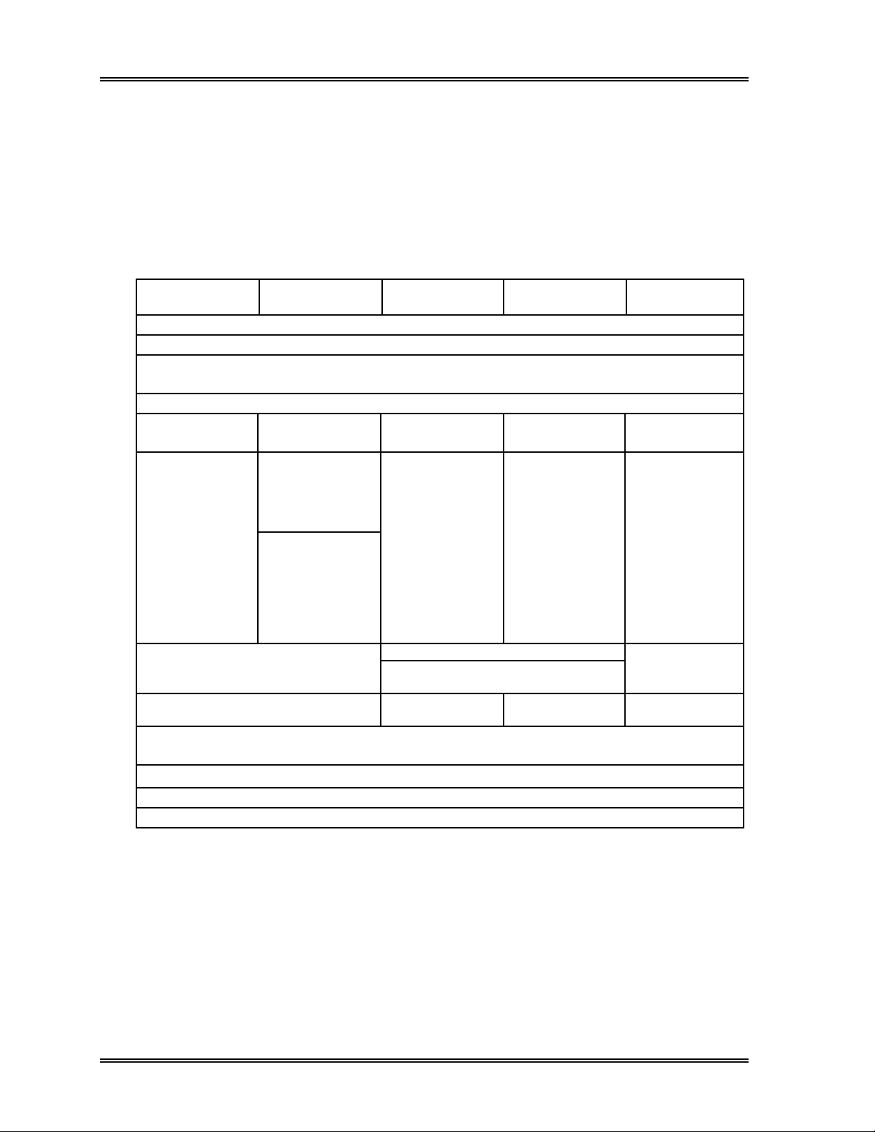
Table 1-1: Manual Organization
CHAPTER 1
Introduction
CHAPTER 2
Sample Processing
CHAPTER 3
Work List
CHAPTER 4
Result Interpretation/
Reports
CHAPTER 5
Maintenance and Supplies
CHAPTER 6
Quality Control
CHAPTER 7
Calibration
Contains basic information about the instrument; operating procedures,
screen displays, touch panel, installation and safety. This chapter must be
read prior to operating the Sysmex SF-3000.
Explains sampling procedure from start-up to shutdown. All sampling
operation procedures are contained in this chapter.
Explains how to enter order information with the display and management of
the records.
Explains procedures for displaying and processing Stored Data, and
procedures for analyzed result output. Also explains IP messages.
Explains periodic maintenance, and the procedures for replacing
consumables and reagents.
Explains how to run the Quality Control Program. Also explains, for your
reference, the quality control system used in this instrument.
Explains the procedures for auto-calibration and manual calibration.
CHAPTER 8
Troubleshooting
CHAPTER 9
Adjustments
CHAPTER 10
Functional Descriptions
CHAPTER 11
System Setup
APPENDICES A, B, C
Menu Tree, Installation
and Technical Information
Explains error messages and their troubleshooting. Also explains service
data and system test functions.
Explains how to adjust pressure and other adjustments.
Gives the main principles of analysis performed by the instrument. Also
contains system nomenclature.
Explains how to set date, time, units, sample analysis stop and other system
conditions. Also contains data analysis settings -- for abnormal data
judgments, etc.
Contains program menu tree, technical information including unpacking check
lists, installation procedures, bar-code labeling parameters and host
communication protocols.
1-2 Sysmex SF-3000 Operator's Manual -- Revised September 1995
Page 16
INTRODUCTION
3. INFORMATIONAL HEADINGS
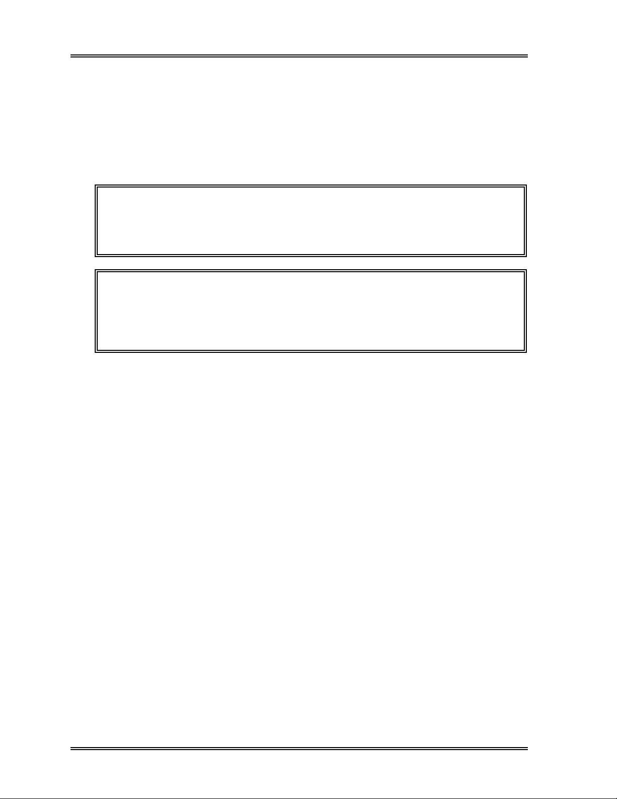
3.1 NOTE, CAUTION and WARNING
NOTE, CAUTION and WARNING boxes throughout this manual are meant to get to
attention to important safety and operational information. Always follow the instructions
contained in the boxes. Failure to do so may affect the safety or precision features of the
SF-3000 analyzer. The boxes are defined as follows:
NOTE: Highlights important facts, gives helpful information, and clarifies
procedures.
CAUTION: Provides information on the correct operation of the SF-3000 analyzer.
Information contained in CAUTION boxes is crucial to prevent damage
and to maintain performance of the analyzer.
WARNING! Indicates potentially hazardous situations that could result in serious
injury or infection to laboratory personnel.
3.2 Document Conventions
The SF-3000 Operator's Manual uses the following conventions:
"Quotations": Screen commands, messages, and status information that the SF3000 system displays appear within quotation marks. For example:
"All Samples", "Ready" or "Input Password"
[Square Brackets]: Names of function keys such as control or operational keys,
number keys, or arrow keys that you select on the SF-3000 appear within square
brackets. For example:
[Enter], [Sampler], [2] or [↑]
Italics: Application names and reference material appear in italic form. For
example:
Refer to Chapter 2: Sample Processing.
Sysmex SF-3000 Operator's Manual -- Revised September 1995 1-3
Page 17
INTRODUCTION
4. SYSTEM OVERVIEW
The purpose of the SF-3000 is to provide accurate results on 23 parameters and to detect
abnormalities in the sample. To assist the laboratory in the screening of abnormalities,
the SF-3000 analyzes and processes the data obtained from the analyzer unit, and the
LCD displays and outputs either a POSITIVE or a NEGATIVE message for each sample.
A NEGATIVE message signifies that parameter values for the sample are within
acceptable limits and the sample does not require any additional verification of those
values. A POSITIVE message signifies that the sample is not within the acceptable limits
and requires further review and investigation. Proper use of the instrument requires each
laboratory to establish the acceptable limits for results.
The SF-3000 uses the optical detector block incorporating the semiconductor laser to
analyze the WBC population. In the DIFF channel, lymphocytes, monocytes,
eosinophils, and the group of neutrophils and basophils are analyzed to determine the
WBC 4-differentials using flow cytometry. Basophil determination and WBC number
counting are performed in the BASO channel. RBCs and PLTs are analyzed by the RBC
detector block using the DC detection method. HGB determination is performed using
the SLS hemoglobin detection method.
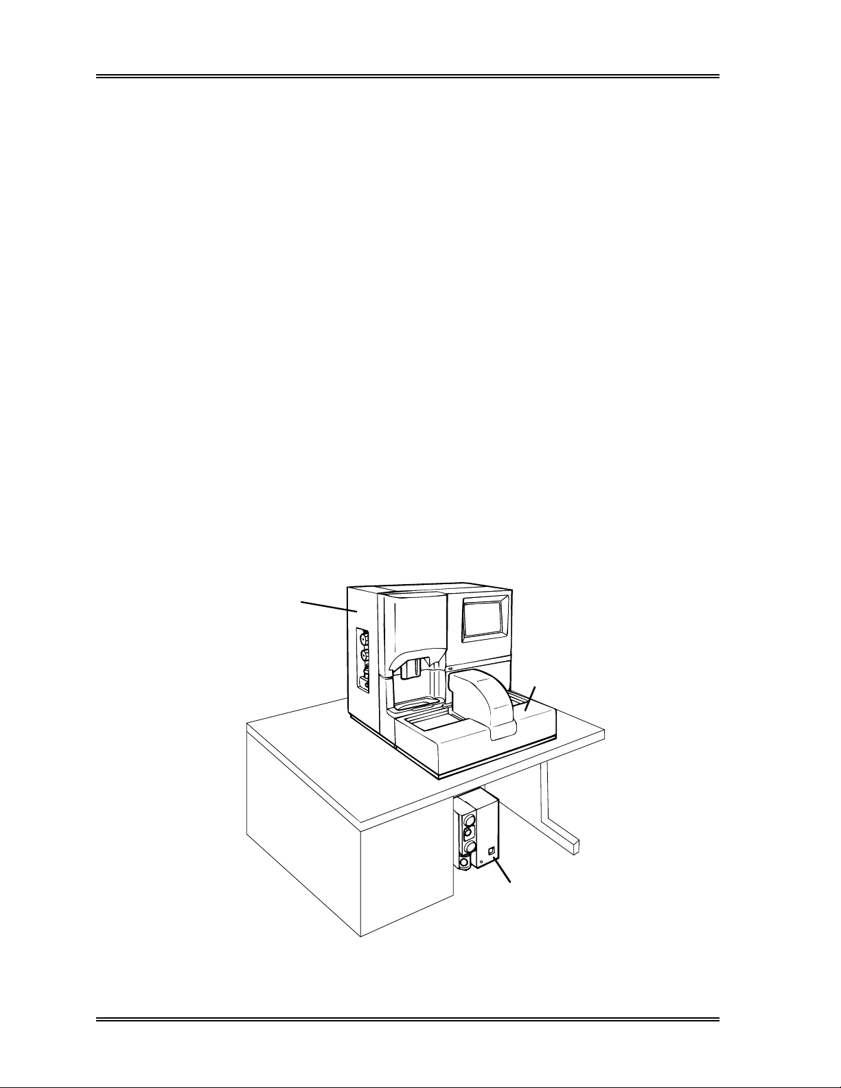
The SF-3000 consists of two major systems.
• Main Unit : Houses the hydraulic and electronic systems and their control
components. The unit analyzes, processes and displays the data
on the LCD screen.
• Pneumatic Unit : Supplies the required pressure and vacuum for analysis.
Main Unit
Sampler Unit
(Optional)
Pneumatic Unit
Figure 1-1: Sysmex SF-3000 Hematology Analyzer
1-4 Sysmex SF-3000 Operator's Manual -- Revised September 1995
Page 18

INTRODUCTION
5. SYSTEM OPTIONS
Several options are available to enhance system efficiency. Available options for the
SF-3000 are:
• ID Bar Code Reader : Reads the ID numbers of bar code labeled samples,
and inputs the numbers automatically.
• Color Graphics Printer : Prints out analysis results (cell size distribution
or Page Printer graphs, scattergrams) and hard copies of screens in
color or black and white.
Printing can be done both in graphic and list format.
• Data Printer : Prints the analysis data in ticket format.
• (Cap Piercing) Sampler Unit : Consists of a mixer and a cap piercer unit, and loads
up to 5 sample racks (50 sample tubes) that enable an
automated closed sampling system.
• Manual CP Unit : Consists of a mixer and a cap piercer unit which
enables a manual closed sampling system.
Sysmex SF-3000 Operator's Manual -- Revised September 1995 1-5
Page 19

INTRODUCTION
6. SAFETY
The operator must follow the instructions in this section. It contains important
information to operate the SF-3000 analyzer safely.
6.1 General Safety
While operating, maintaining, servicing or repairing the system, follow all procedures
contained in this manual. The operator must observe all NOTES, CAUTIONS and
WARNINGS posted anywhere on the instrument or given in this manual.
Do NOT touch the electrical circuits behind the enclosure panels of the SF-3000.
Touching the circuits is dangerous and may give you an electrical shock, especially if
your hands are wet.
Use only designated tools and parts for service and repair. Substitute parts should never
be used, and the SF-3000 should not be modified in any way.
Keep hair, clothing and fingers away from all moving parts.
Install the Sampler Unit on a table or work bench to prevent the system from accidentally
falling.
6.2 Hazardous and Biohazardous Material
All surfaces and components in contact or potentially in contact with patient blood
samples should be considered contaminated. Use of protective garments and gloves is
strongly recommended when operating, maintaining, or servicing the SF-3000.
Do not touch the waste when disposing of it or assembling/disassembling the associated
parts. If accidental contact with waste or any other potentially biohazardous material
occurs, flush the affected area immediately with water and follow your laboratory's
prescribed cleaning and decontamination procedures.
Consider all regulations applicable to your laboratory when operating the Sysmex
SF-3000 instrument.
6.3 Reagent Safety
If reagent comes into contact with skin or clothing, flush it with water. If eyes are
affected, flush with copious amounts of water and obtain medical advice if necessary.
1-6 Sysmex SF-3000 Operator's Manual -- Revised September 1995
Page 20
INTRODUCTION, Safety
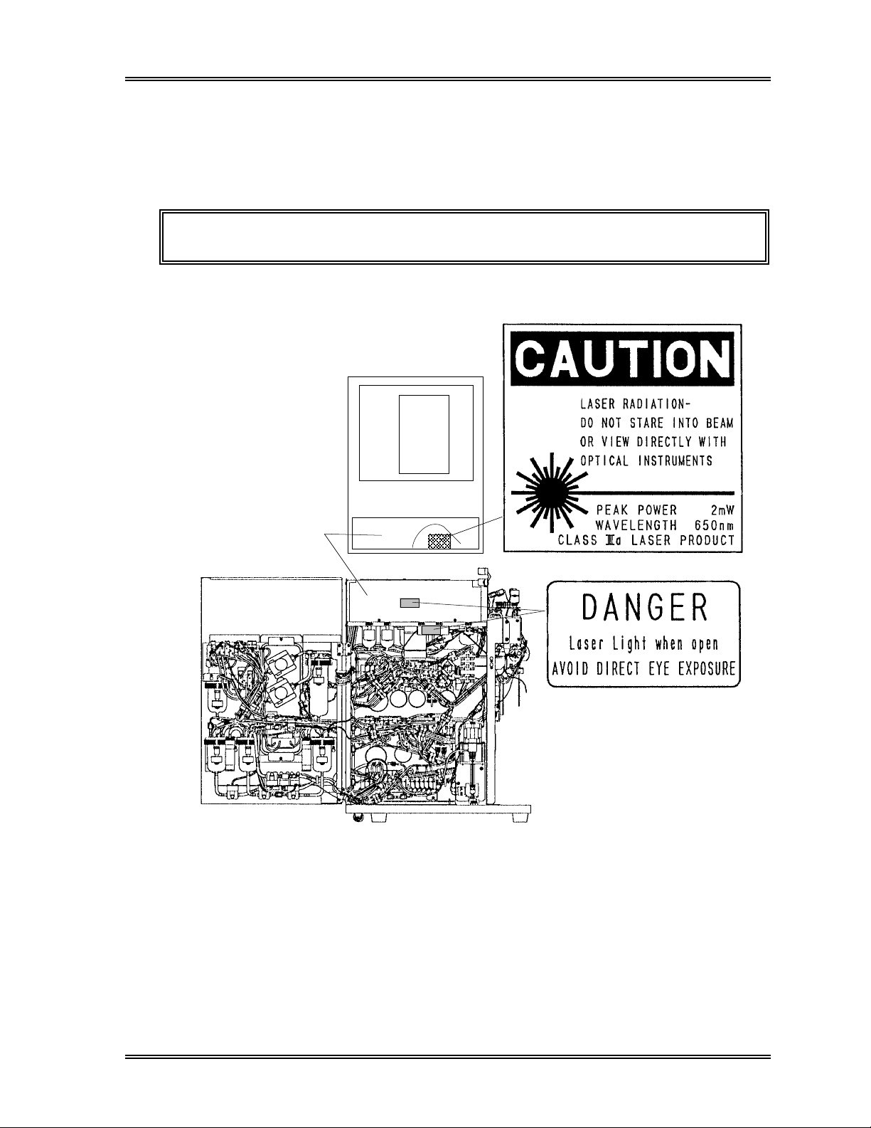
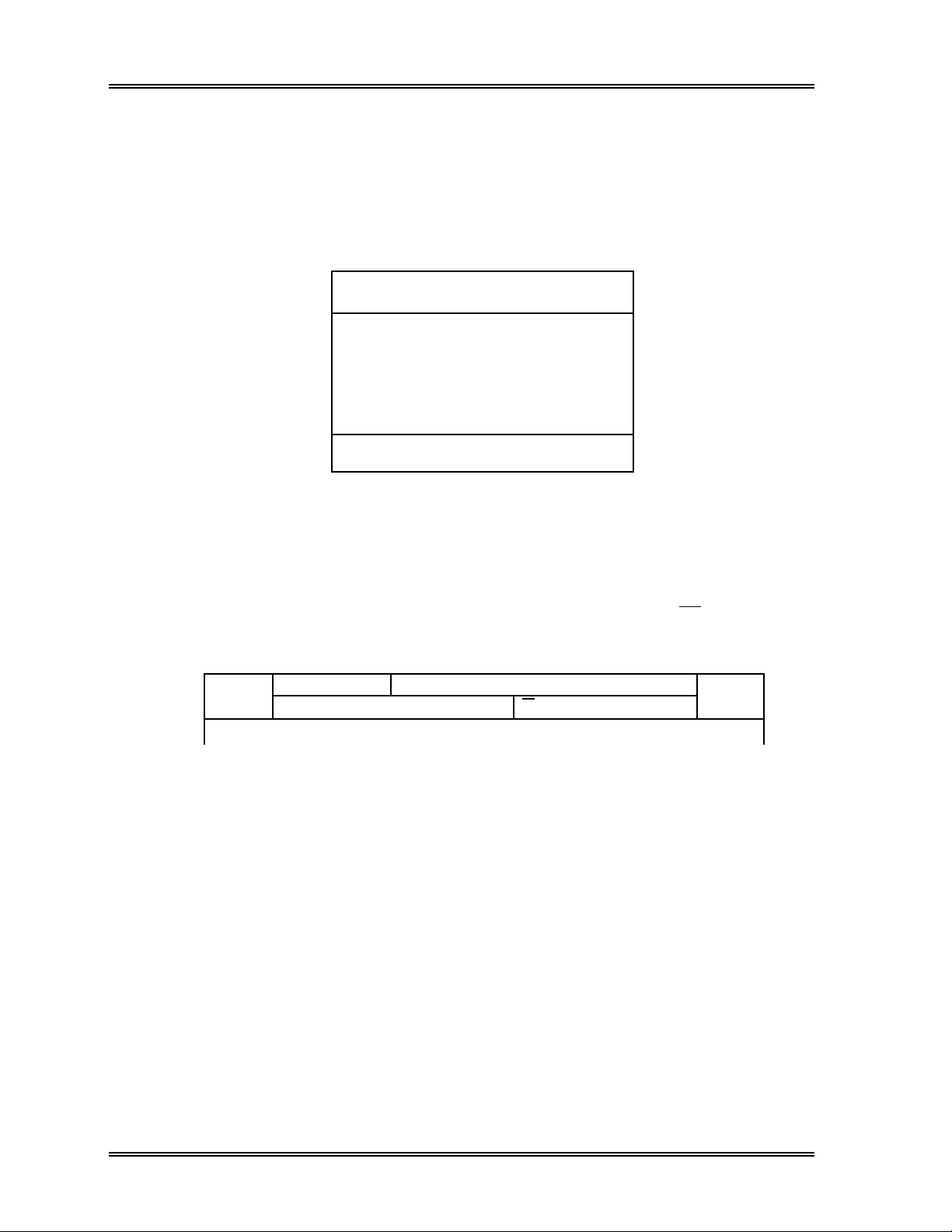
6.4 Laser Safety
The SF-3000 uses a semiconductor laser unit. Though this laser unit is placed in the
shield box, the operator must observe all NOTES, CAUTIONS and WARNINGS
concerning laser handling.
WARNING!: DO NOT remove the shield box cover of the Laser Unit.
NOTE: This caution label is located
inside the Laser Unit Cover.
< Top View >
Semiconductor Laser
Unit Cover
< Left Side View >
Figure 1-2: Location of Laser Unit and Labels
(Left Interior of the Main Unit)
Refer to Chapter 5, Section 6 for further information on laser handling.
Sysmex SF-3000 Operator's Manual -- Revised September 1995 1-7
Page 21
INTRODUCTION
7. OPERATIONAL SUMMARY
The SF-3000 has two basic operating modes: the Manual Open Mode and Capillary
Mode. Additional three operating modes are available by means of optional units: the
Sampler Mode and Manual Closed Mode by means of Cap Piercing Sampler Unit, and
Manual CP Mode by means of Manual CP Unit.
Table 1-2: Operation Modes
Manual Open
Mode
Select
manual mode
Set manual
sample ID
Set sample at manual Place sample in rack Place sample
aspiration pipette
Press the Start Switch
Capillary Mode Sampler Mode Manual Closed
Mode
Operator checks
Turn ON power
Self-check
Auto rinse
Ready
Select
capillary mode
Prepare
capillary
analysis
sample
(1:5 dilution)
Set capillary
sample ID
Analysis performed
Analysis complete
Post-analysis check
Perform shutdown
Press
[Sampler]
Set sample ID
(or read bar
code label)
Set rack No.
Set tube No.
Set rack on sampler in Manual CP
Press [Start] Press the
Power OFF
Select
closed mode
Set closed
sample ID
Start Switch
Manual CP
closed mode
Set closed
sample ID
Unit
Press the
Start Switch
Mode
Select
Operations performed by the operator are indicated in bold print.
Ready: READY LED turns on and "Ready" message is displayed on the LCD screen.
In this state, various operations can be performed, including analysis setting
and data processing.
1-8 Sysmex SF-3000 Operator's Manual -- Revised September 1995
Page 22

INTRODUCTION
8. ANALYSIS PARAMETERS
The SF-3000 uses 4 detection methods and 5 types of reagents to analyze the following
23 parameters:
Table 1-3: Analysis Parameters
Parameter Acronym Detection Method
White Blood Cell Count WBC Flow Cytometry by Semiconductor Laser
Red Blood Cell Count RB C DC
Hemoglobin Concentration HGB SLS hemoglobin
Hematocrit (true relative percentage volume
of erythrocytes)
Mean Corpuscular (erythrocyte) Volume MCV Computed from RBC and HCT
Mean Corpuscular Hemoglobin MCH Computed from RBC and HGB
Mean Corpuscular Hemoglobin
Concentration
Platelet Count PLT DC
Neutrophil Percent NEUT%
Lymphocyte Percent LYMPH%
Monocyte Percent MONO% Flow Cytometry by Semiconductor Laser
Eosinophil Percent EO%
Basophil Percent BASO%
Neutrophil Count NEUT#
Lymphocyte Count LYMPH#
Monocyte Count MONO# Flow Cytometry by Semiconductor Laser
Eosinophil Count EO#
Basophil Count BASO#
RBC Distribution Width RDW-SD Computed
RBC Distribution Width RDW-CV Computed
Platelet Distribution Width PDW Computed
Mean Platelet Volume MPV Computed
Platelet Large Cell Ratio P-LCR Computed
H CT RBC Cumulative Pulse Height Detection
MCHC Computed from HCT and HGB
NOTE:
Customers in the United States:
Platelet Distribution Width (PDW) and
Platelet Large Cell Ratio (P-LCR) parameters have not been approved
for reporting by the Food & Drug Administration (FDA). The obtained
values should be excluded from all print forms until reporting approval has
been obtained. See
Chapter 11
for information on excluding these
values.
Sysmex SF-3000 Operator's Manual -- Revised September 1995 1-9
Page 23
INTRODUCTION
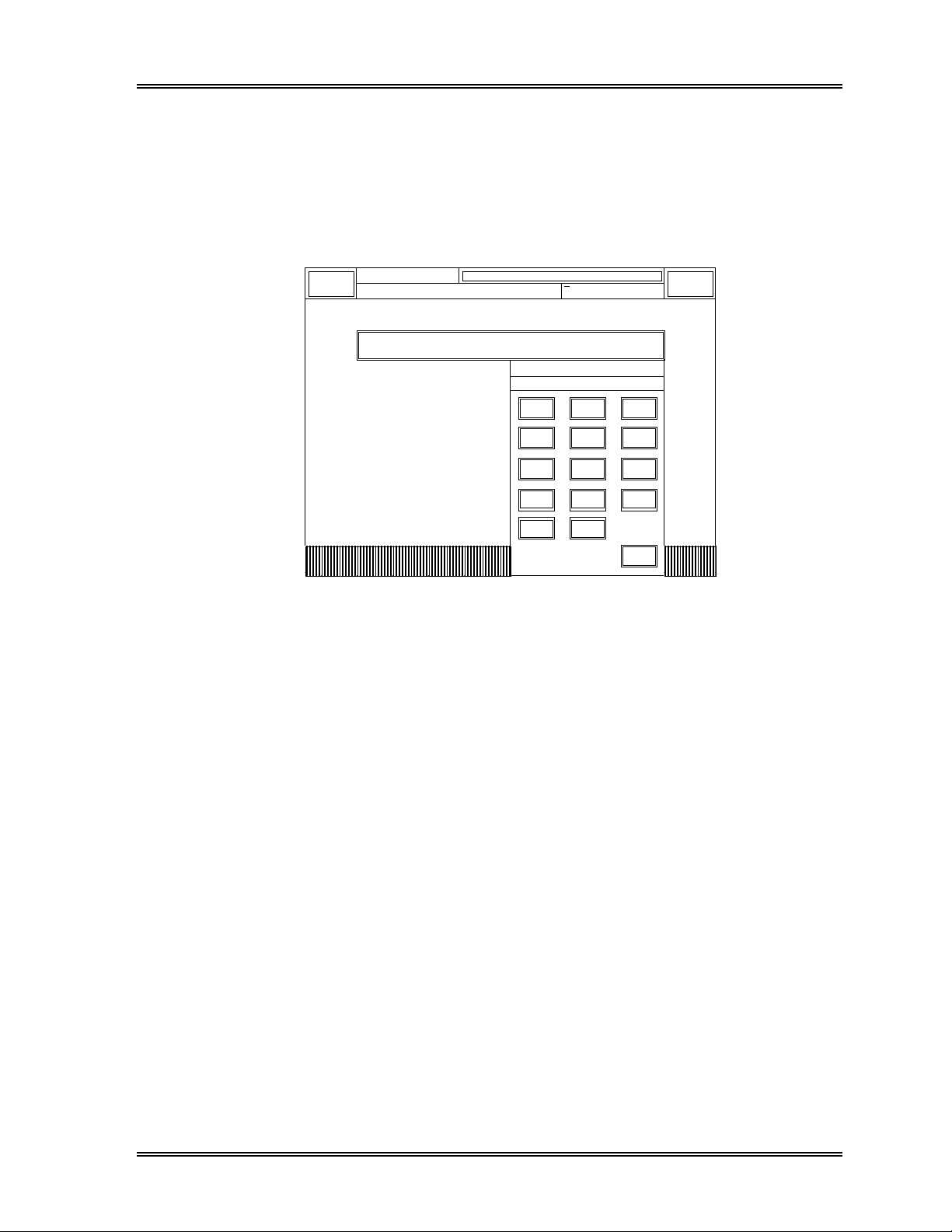
9. DISPLAY SCREEN
9.1 LCD (Liquid Crystal Display) Screen
The LCD screen is divided into 3 parts: the System Status Area, the Data Processing
Area, and the Menu Area.
1. System Status Area
2. Data Processing Area
3. Menu Area
Figure 1-3: Display Screen
1 . System Status Area
The System Status Area appears as the top two lines of the screen (Figure 1-4).
This area displays Main Unit status information such as analysis status, errors, etc.
It also displays data processing status information such as Peripherals, X M, etc.
The [Sysmex] and [Sampler] function keys also appear in this area.
Sysmex
Ready Manual Mode
DP: 1234567890123 XM H C G P D P S U I D
Next No.1234567890123
Sampler
Figure 1-4: System Status Area
• Analysis Status
System status -- "Ready", "Not Ready", etc. is displayed to the left of the top line.
Analysis mode and the next sample ID number --
Analysis mode in which the system is set, and the next sample number to be
analyzed in the selected analysis mode are displayed.
Pressing this keypad displays the Sample No. Setting Screen for the Open
Sampling, Closed Sampling, or Capillary Sampling Manual mode. Using this
setting screen, the analysis mode, next sample ID number for the selected analysis
mode can be set up.
When the Capillary mode is selected, this area is displayed in yellow back-light.
1-10 Sysmex SF-3000 Operator's Manual -- Revised September 1995
Page 24

INTRODUCTION, LCD Screen
NOTE: To set the next Sample ID No., Rack No. and Tube Position No. to be
analyzed in the auto mode by means of Sampler Unit, press [Sampler]
keypad to display the auto mode setting window.
The DP No. is displayed below the system status. If the Data Printer (DP) is the selected
output device, the DP No. displayed indicates the next sample data number to be printed
out.
Errors -- "2.0 kg/cm
2
Error", "Rack Move Error", etc. is displayed below the system
status, in place of the DP No. If 2 or more errors occur simultaneously, they are
displayed in order of importance. When an error is displayed, press [Sysmex] key to
display the action/help messages provided in the Error Log program. Refer to Chapter 8:
Troubleshooting for the action message display.
• Data Processing Status
X M : Indicates the status of X M control (one file of the QC program) in the
following way:
No indication : X M control is not in use (Stop).
X M :XM control is in use (Start).
X M (with red back-light) : X M Limit Error has occurred.
HC : Indicates transmission status of data to the Host Computer.
No indication : The Host Computer is set to "Not Connected".
HC : Ready for transmission to Host Computer.
HC (with green back-light) : Now transmitting to Host Computer.
HC (with red back-light) : Transmission to Host Computer not occurring
because of abnormality in Host Computer.
HC (with yellow back-light) : Error ("Not Transmissible", "No Ack" or "Ack
Code Err") has occurred between SF-3000 and
Host Computer.
GP : Indicates the status of the Graphic Printer (or Line Printer).
No indication : The Graphic Printer is set to "Not Connected".
GP : The Graphic Printer is ready.
GP (with green back-light) : Data being output to Graphic Printer.
GP (with red back-light) : Printing not possible because of abnormality in
Graphic Printer.
DP : Indicates the status of the Data Printer.
No indication : The Data Printer is set to "Not Connected".
DP : The Data Printer is ready.
DP (with green back-light) : Data being output to Data Printer.
DP (with red back-light) : Printing not possible because of abnormality in
Data Printer.
Sysmex SF-3000 Operator's Manual -- Revised September 1995 1-11
Page 25

INTRODUCTION, LCD Screen
SU : Indicates the status of the Sampler Unit.
No indication : The Sampler Unit is not connected.
SU : Sampler Unit ready for sampler analysis.
SU (with red back-light) : Sampler not operational because of abnormality
in Sampler Unit.
CP : Indicates the status of the Manual Cap Piercing (CP) Unit.
No indication : The Manual CP Unit is not connected.
CP : Manual CP Unit ready for manual closed mode
analysis.
CP (with red back-light) : Manual closed mode not operational because of
abnormality in Manual CP Unit.
ID : Indicates the status of the ID Bar Code Reader.
No indication : The Bar Code Reader is set to "Not
Connected".
ID : The Bar Code Reader is ready.
ID (with red back-light) : "ID Unit Com. Error" has occurred between
SF-3000 and Bar Code Reader.
HD (with green backlight) : Appears when the system hard disk is being accessed.
• Function Keys
The [Sysmex] and [Sampler] keypads appear at each end of this area.
[Sysmex] -- Press this key to obtain the hard copy of screen and to access the Error Log.
Refer to Section 9.3 in this chapter for hard copy output. Refer to Chapter 8:
Troubleshooting for Error Log.
When an error occurs, this key changes to [Alarm Reset] with red backlight. Press to
stop the alarm.
[Sampler] -- Press to display the sampler start check window, where the Sample ID No.,
Rack No. and Tube Position No. for the next auto mode analysis can be set up. This
keypad changes to [Sampler Stop] during auto mode analysis.
2 . Data Processing Area
Analysis and sample information, including analysis data, scattergrams, cell size
distributions, QC menus, action messages, sub-program menu keypads, etc. are
displayed in the center area of the display screen.
1-12 Sysmex SF-3000 Operator's Manual -- Revised September 1995
Page 26
INTRODUCTION, LCD Screen
3 . Menu Area
The available menu choices are displayed in the bottom line of the display screen. Touch
the desired keypad on the LCD to access and proceed for the program. In the Main
Screen, the Root Menus appear in this area. Refer to Section 9.2 in this chapter for the
root menus.
NOTE: The program keys masked as shown below do not function when
pressed.
Figure 1-5: Example of Masked Program Keys
4 . Power Saving Function
The LCD contrast will automatically decrease for the LCD power saving if the Main Unit
does not detect any key operation on the LCD for 5 minutes. Touch anywhere on the
LCD to exit the power saving mode.
Sysmex SF-3000 Operator's Manual -- Revised September 1995 1-13
Page 27

INTRODUCTION
9.2 Root Menus
When the instrument power is ON, the Main Screen with the Root Menus is displayed as
the initial screen. By pressing the [Return] key on any screen, the visible display returns
to the previous screen, finally to the Main Screen.
The SF-3000 provides twelve Root Menus. The Main Screen displays seven Root
Menus on the menu line at a time. When you want to change a menu, press the [More]
key to alternate root menu.
The Root Menus is listed below. Each Root Menu consists a second menu(s) or menu
choices to proceed for the corresponding program.
[Status]
Use this menu to check the analyzer condition, analysis process, sensor status, etc. at
any time. (This menu does not display analysis errors.)
[Work List]
Use this menu to display, register, and process the analysis information, including
Sample No., Rack No., Tube Position, Order Information, etc. Refer to Chapter 3:
Work List for more information.
[Stored Data]
This menu provides options to display analysis results up to 1,000 samples stored in the
memory. The Stored Data List includes Date and Time analyzed, Sequential No.,
Sample No., Rack No., Tube Position, output status to the peripherals, flag information
and analysis results. Refer to Chapter 4: Result Interpretation/Reports for more
information.
[QC]
The SF-3000 quality control program provides X or L-J, and X M control
applications. The QC Root Menu performs QC analysis, displays and/or outputs the QC
Chart, establishes the QC settings, etc. Refer to Chapter 6: Quality Control for more
information.
[GP Print]
Use this menu to get options to output the data currently displayed on the screen to the
Graphic Printer.
[DP Print]
Use this menu to get options to output the data currently displayed on the screen to the
Data Printer.
[Replace Reagent]
Use this menu after replacing a reagent container to prime the reagent into internal
reservoir chamber.
1-14 Sysmex SF-3000 Operator's Manual -- Revised September 1995
Page 28

INTRODUCTION, Root Menu
[Mainte.]
Use this menu to perform the customer maintenance programs, such as waste chamber
cleaning, clog removal, etc. and to perform the system test programs.
[Settings]
Use this menu to set the system parameters and conditions, such as date, time, units,
analysis stop condition, etc. Also this program contains data analysis settings to
establish certain standards for the SF-3000 system. System's operational parameters can
be set up to meet individual laboratory preferences to customize the operation of the
SF-3000. Refer to Chapter 11: System Setup for the setup procedure.
[Calib.]
Use this menu to calibrate the SF-3000 for specified parameter(s) automatically or
manually. Refer to Chapter 7: Calibration for the procedure.
[Shutdown]
Use this menu to clean the detector chambers and all hydraulic lines in the SF-3000
system with detergent.
[Auto Rinse]
Use this menu to rinse the hydraulic lines with the diluents, and check the background
values after rinsing. If the background values exceed the preset limit values, a
"Background Error" occurs.
Sysmex SF-3000 Operator's Manual -- Revised September 1995 1-15
Page 29
INTRODUCTION
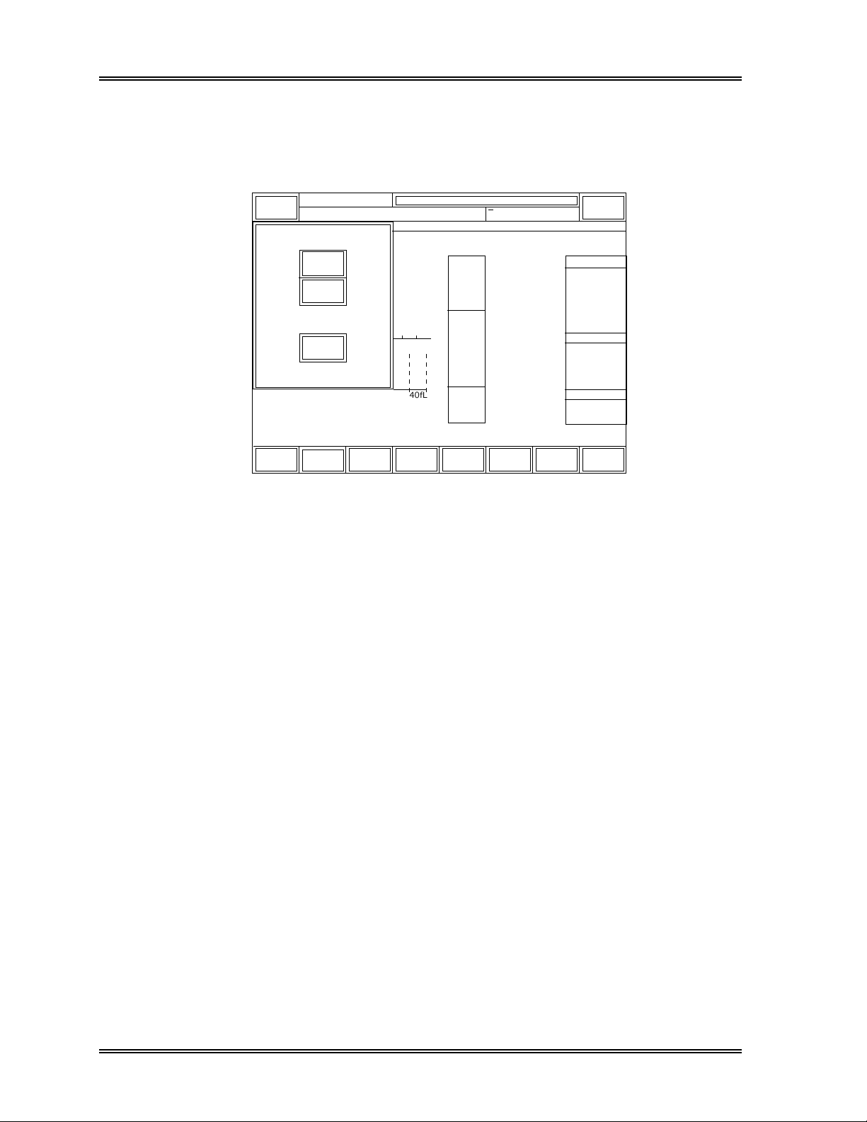
9. 3 Hard Copy
The [Sysmex] keypad always appears on the left of the top line of the screen.
Press this key to display the Sysmex submenu window as shown in Figure 1-6.
Sysmex
Status
Ready
DP:1234567890123
Hard
Copy
Error
Log
Cancel
Work
List
Manual Mode Next No.1234567890123
NO. R :
WBC
NEUT
LYMPH
MONO
EO
BASO
RBC
HGB
HCT
MCV
MCH
MCHC
RDW-SD
RDW-CV
PLT
PDW
MPV
P-LCR
Q C
G P
Print
Stored
Data
B A S O
40fL
XM HC GP DP SU
3
[x10 /uL]
6
[x10 /uL]
[g/dL]
[%]
[fL]
[pg]
[g/dL]
[fL]
[%]
3
[x10 /uL]
[fL]
[fL]
[%]
D P
Print
Replace
Reagent
[%]
[%]
[%]
[%]
[%]
Sampler
WBC Flag
RBC Flag
PLT Flag
More
Figure 1-6: Sysmex Submenu Window
[Hard Copy]
Pressing this key outputs the hard copy of screen (screen shot), as displayed on the LCD
at the time of pressing the [Hard Copy] keypad, to the Graphic Printer. This function is
available in any status of instrument operation. The window will close automatically
after pressing this key.
[Error Log]
Pressing this key displays the error log and action/help messages for a specified error.
Refer to Chapter 8: Troubleshooting.
[Cancel]
Pressing this key closes the Sysmex submenu window.
1-16 Sysmex SF-3000 Operator's Manual -- Revised September 1995
Page 30
INTRODUCTION
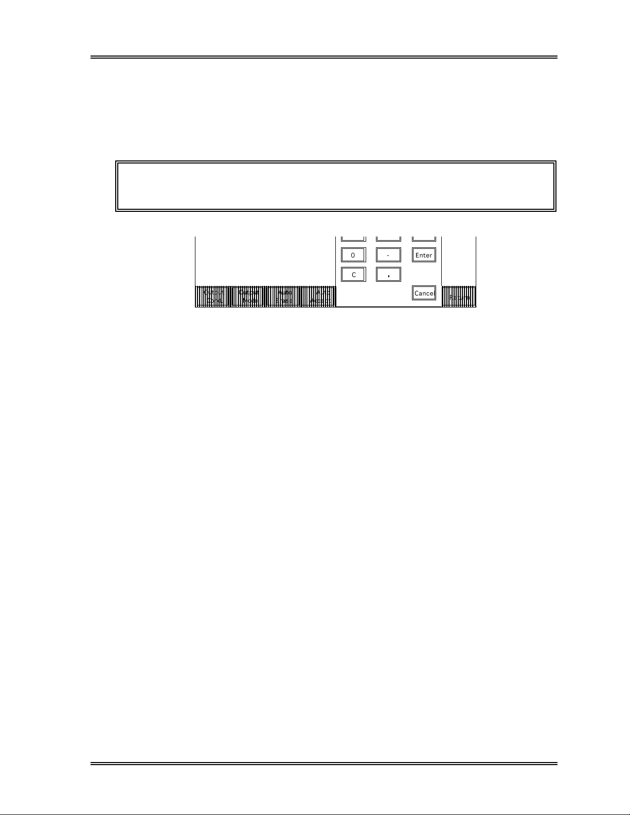
10. PASSWORD
Some programs in Q.C., Settings and Calibration require a password entry to prevent
unauthorized changes of the important settings and values. When such a program is
selected, the Password Input Screen appears with the message "Input Password". Enter
the registered password and press the [Enter] key. If the entered password is correct, the
program will be executed.
Sysmex
Ready
DP:1234567890123
Manual Mode Next No.1234567890123
XM HC GP DP SU
Input Password
Password
***
7 8
4
1 2 3
0 Ð Enter
C
.
Cancel
Sampler
9
65
Figure 1-7: Password Entry Screen
The password is important for the management of the SF-3000, so be sure to memorize it
and/or have aids to help you remember it. Should you forget it, consult your Sysmex
service representative.
The password can consist of up to 12 digits. If you set the password to "0", no
password check will be performed, and the programs will be executed without the need
of password input.
For the procedures for setting and changing the password, refer to Chapter 11, "System
Setup".
Sysmex SF-3000 Operator's Manual -- Revised September 1995 1-17
Page 31
INTRODUCTION
11. EMERGENCY SHUTDOWN PROCEDURE
Should the analyzer need to be shut down in an emergency, such as a power failure in the
laboratory, turn OFF the power switches of the following major components before the
power is restored:
• Main Unit
• Pneumatic Unit
NOTE: If the Main Unit power is turned OFF during the system hard disk is
being accessed ("HD" indicator appears in the System Status Area),
the system memory check will be performed at next power ON. It will
take approx. 15 minutes to complete the memory check.
NOTE: When the system is restarted and becomes ready status, perform the
Waste Chambers and the WBC Detector cleaning sequences to
remove the potentially remained sample and reagent in the hydraulic
lines. Refer to
procedures.
Chapter 5: Maintenance and Supplies
for the
12. ALARMS
In the SF-3000, 3 types of alarm sounds are used to alert the operator:
1. Key Entry
A short beep (approx. 0.1 sec.) sounds every time a key is pressed on the LCD
touch panel keypad.
2. Operation Error
A long beep (approx. 1 sec.) sounds when a wrong key is pressed on the LCD touch
panel keypad.
3. Analysis Error
If any abnormality occurs in the Main Unit, a beep sounds and continues sounding
until the [Alarm Reset] keypad is pressed. This keypad appears at the top left corner
of the LCD instead of [Sysmex] keypad.
1-18 Sysmex SF-3000 Operator's Manual -- Revised September 1995
Page 32

INTRODUCTION
13. INSTALLATION REQUIREMENTS
13.1 Relocation Information
The SF-3000 and associated equipment should only be installed by your Sysmex service
representative. Contact your Sysmex service representative if relocation of the system is
required after it has been installed.
NOTE: Problems resulting from the relocation of the SF-3000 by anyone other
than a Sysmex service representative are not covered by the
Warranty.
The service agreement covers moving the SF-3000 after the warranty period has expired.
13.2 Electrical Requirements
The SF-3000 comes equipped with a three-prong or two-prong plug power cord. The
type of cord and plug supplied depends on the source voltage for the system.
Figure 1-8: 117 VAC Plug Figure 1-9: 220 VAC Plug Figure 1-10: 240 VAC Plug
WARNING!: Proper use of the appropriate power cord assures adequate grounding
for the system. Failure to properly ground the SF-3000 bypasses
important safety features and may result in an electrical hazard.
The power source required for the SF-3000 system is: 117, 220 or 240 VAC ± 10%,
50/60 Hz.
The power consumption of the system, including the Pneumatic Unit and Sampler Unit,
is 600 VA or less.
Sysmex SF-3000 Operator's Manual -- Revised September 1995 1-19
Page 33

INTRODUCTION
13.3 Space Requirements
It is important to install the instrument in a suitable location. A poor location can
adversely affect its performance. Consider the following space requirements:
• Select a location near a power source and close to a suitable drain.
• Leave at least 0.5 m space on both sides, and at the rear and top of the system for
easy maintenance and servicing. A minimum of 0.2 m must be maintained between
the rear panel and the wall to allow for heat dissipation and tube clearance.
• Install the Pneumatic Unit, reagents and printers in suitable places that will make your
work easy.
WARNING!: Install the Sampler Unit on a table or work bench. If the Sampler Unit
is installed without supporting desktop under the unit, there is a
possibility that the SF-3000 system could accidentally fall.
13.4 Installation Environment
The environmental requirements are listed below:
• Operate the SF-3000 within a temperature range of 15 - 30°C (optimum temperature
25°C) and relative humidity of 30 - 85%.
• To compensate for heat generated by the system, approximately 430 kcal/hour (1705
BTU/hour) is required in an air-conditioned environment. (This figure does not
include additional cooling capacity required for the optional printers.)
• Avoid using the SF-3000 in areas of extreme temperature and direct sunlight.
• Place the SF-3000 in a well ventilated location.
• Avoid placing the SF-3000 near potentially interfering devices capable of emitting
radio frequencies such as a radio or television receiver.
1-20 Sysmex SF-3000 Operator's Manual -- Revised September 1995
Page 34

14. SYSTEM SPECIFICATIONS
Table 1-4: System Specifications
INTRODUCTION
Parameters WBC, NEUT%, LYMPH%, MONO%, EO%, BASO%, NEUT#, LYMPH#,
Reagents Diluents : 1 (CELLPACK)
Aperture Diameter RBC, PLT 75 µm
Throughput Approximately 80 samples per hour
Principles WBC, LYMPH, MONO, NEUT, EO, BASO
MONO#, EO#, BASO#, RBC, HGB, HCT, MCV, MCH, MCHC, RDW-SD,
RDW-CV, PLT, PDW, MPV, P-LCR
WBC Reagents : 3 (STROMATOLYSER-FD (I),
STROMATOLYSER-FD (II),
STROMATOLYSER-FB)
HGB Reagent : 1 (SULFOLYSER)
Detergents : 1 (CELLCLEAN)
(Approx. 85 seconds per sample)
: Flow Cytometry with semiconductor laser beam
RBC, PLT : DC Detection Method
HGB : SLS Hemoglobin Method (at wavelength 555 nm)
HCT : Cumulative Pulse Height Detection Method
MC V : Calculated from RBC and HCT
MCH : Calculated from RBC and HGB
MCHC : Calculated from HCT and HGB
Sample Volume Required Sampler Mode : Approx. 270 µL
Data Storage Capacity Cell size distribution data (with graphs) : for 1,000 samples
Quality Control
Closed Mode : Approx. 270 µL
Manual Mode : Approx. 170 µL
Capillary Mode : Over 40 µL
Scattergrams : for 1,000 samples
Order information : for 50 samples
QC files : for 13 QC files
X
Control (or L-J Control) : 180 points x 12 files, 28 parameters
M Control : 180 points x 1 file, 28 parameters
X
Sysmex SF-3000 Operator's Manual -- Revised September 1995 1-21
Page 35

INTRODUCTION
Table 1-4: System Specifications (Continued)
Precision
for Closed and
Open mode
Precision Characteristics are determined during instrument evaluation using
one fresh normal whole blood sample analyzed ten times consecutively in
Closed Sampling Auto Mode or Open Sampling Manual Mode.
WB C CV 3.0% (when WBC ≥ 4.0 x 10
NEUT% CV 8.0% (when NEUT% ≥ 30.0% and WBC ≥ 4.0 x 10
LYMPH% CV 8.0% (when LYMPH% ≥ 15.0% and WBC ≥ 4.0 x 10
MONO% CV 20.0% (when MONO% ≥ 5.0% and WBC ≥ 4.0 x 10
EO% CV 25.0% or within ± 1.5 EO% (when WBC ≥ 4.0 x 10
BASO% CV 40.0% or within ± 1.0 BASO% (when WBC ≥ 4.0 x 10
NEUT# CV 8.0% (when NEUT# ≥ 1.20 x 10
LYMPH# CV 8.0% (when LYMPH# ≥ 0.60 x 10
MONO# CV 20.0% (when MONO# ≥ 0.20 x 10
EO# CV 25.0% or within ± 0.12 x 10
BASO# CV 40.0% or within ± 0.06 x 10
RB C CV 1.5% (when RBC ≥ 4.00 x 10
3
/µL)
3
/µL)
3
/µL)
3
/µL)
3
/µL
3
/µL
6
/µL)
3
3
/µL)
3
/µL)
3
/µL)
/µL)
3
/µL)
HGB CV 1.5%
HCT CV 1.5%
MCV CV 1.5%
MCH CV 1.5%
MCHC CV 2.0%
PLT CV 5.0% (when PLT ≥ 100 x 10
3
/µL)
RDW-CV CV 3.0%
RDW-SD CV 3.0%
PDW CV 10.0%
MPV CV 4.0%
P-LCR CV 18.0%
Precision
for Capillary mode
Accuracy
for Closed mode
for Open mode
Accuracy
for Capillary mode
Precision Characteristics are determined during instrument evaluation using
one fresh normal capillary blood sample analyzed ten times
consecutively in Open Sampling Manual Mode.
WB C CV 9.0% (when WBC ≥ 4.0 x 10
RB C CV 4.5% (when RBC ≥ 4.00 x 10
3
/µL)
6
/µL)
HGB CV 4.5%
HCT CV 4.5%
MCV CV 4.5%
MCH CV 4.5%
MCHC CV 6.0%
PLT CV 15.0% (when PLT ≥ 100 x 10
WBC within ± 3% or within 0.20 x 10³/µL
RBC within ± 2% or within 0.03 x 10
PLT within ± 5% or within 10 x 10
3
6
/µL
3
/µL
/µL)
WBC within ± 10%
RBC within ± 8%
PLT within ± 12%
1-22 Sysmex SF-3000 Operator's Manual -- Revised September 1995
Page 36
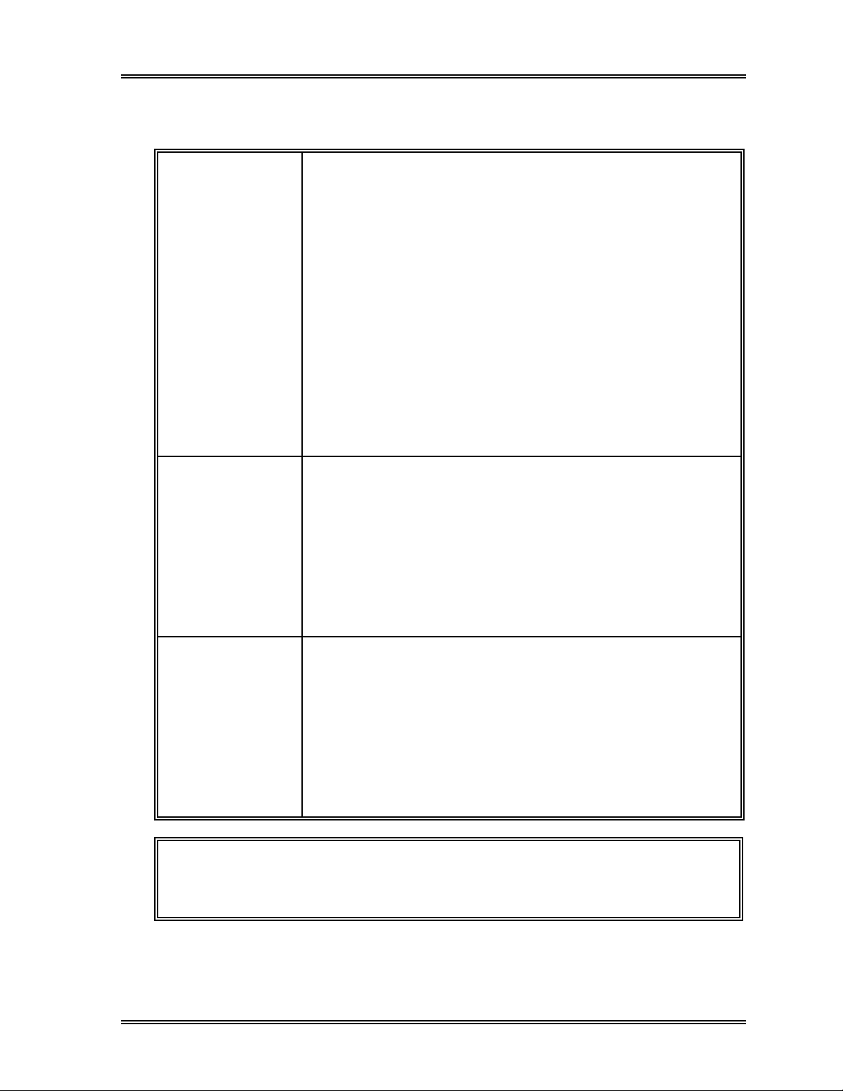
Table 1-4: System Specifications (Continued)
INTRODUCTION
Differential Accuracy The instrument differential is compared by using 100 or more fresh samples
to the reference 400 cell manual differential (200 counts with 2 Lab. Techs.),
as per NCCLS H-20A. MONO% is compared by using the monoclonal
antibodies. Results are displayed as a range of values that are the mean
differences between the methods, expressed to a 95% confidence interval.
NEUT% Coefficient correlation r ≥ 0.90
LYMPH% Coefficient correlation r ≥ 0.90
MONO% Coefficient correlation r ≥ 0.75
EO% Coefficient correlation r ≥ 0.80
BASO% Coefficient correlation r ≥ 0.50
Additionally, the mean difference from that obtained on the standard
instrument should be the following:
NEUT% within ± 3.0 NEUT%
LYMPH% within ± 3.0 LYMPH%
MONO% within ± 2.0 MONO%
EO% within ± 1.0 EO%
BASO% within ± 1.0 BASO%
Linearity
for Closed and
Open mode
WBC within ± 0.30 x 10³/µL or within 3%
for range 1.00-99.99 x 10
RBC within ± 0.03 x 10
6
for range 0.30-9.99 x 10
3
/µL
/µL or within 3%
6
/µL
HGB within ± 0.2 g/dL or within 2%
for range 0.1-25.0 g/dL
HCT within ± 1.0 HCT% or within 3%
PLT within ± 10 x 10
for range 10.0-60.0 HCT%
for range 10-999 x 10
(Condition: RBC count is less than approx. 7.00 x 10
3
/µL or within 5%
3
/µL
6
/µL)
Linearity
for Capillary mode
WBC within ± 0.50 x 10³/µL or within 5%
for range 1.00-99.99 x 10
RBC within ± 0.06 x 10
6
for range 1.00-9.99 x 10
3
/µL
/µL or within 6%
6
/µL
HGB within ± 0.7 g/dL or within 7%
for range 2.0-25.0 g/dL
HCT within ± 2.0 HCT% or within 6%
PLT within ± 20 x 10
for range 10.0-60.0 HCT%
for range 10-999 x 10
(Condition: RBC count is less than approx. 7.00 x 10
3
/µL or within 10%
3
/µL
6
/µL)
NOTE: The Linearity range is different from the Display range. Consult the
Linearity specification for the reportable range for each parameter. The
Display range is given on the next page.
Sysmex SF-3000 Operator's Manual -- Revised September 1995 1-23
Page 37

INTRODUCTION
Table 1-4: System Specifications (Continued)
Carryover WBC 3.0% or less
RBC 1.5% or less
HGB 1.5% or less
HCT 1.5% or less
PLT 1.5% or less
Maximum Allowable Difference
between Manual Open Mode and
Auto Mode
WBC Within ± 0.4 x 10³/µL or ± 5%
RBC Within ± 0.02 x 10
6
/µL or ± 2%
HGB Within ± 0.2 g/dL or ±2%
HCT Within ± 0.3HCT% or ± 2%
PLT Within ± 20 x 10
3
/µL or ± 7%
NEUT% Within ± 5.0% NEUT%
LYMPH% Within ± 4.0% LYMPH%
MONO% Within ± 3.0% MONO%
EO% Within ± 2.0% EO%
BASO% Within ± 1.0% BASO%
Display Range WBC 0.00 - 999.99 x 10³/µL
RBC 0.00 - 99.99 x 10
6
/µL
HGB 0.0 - 30.0 g/dL
HCT 0.0 - 100%
PLT 0 - 9999 x 10
3
/µL
Peripheral Interface Serial port for Host Computer
Parallel port for Data Printer (DP-510, DP-490)
Parallel port for Graphic Printer (DeskJet 560C/560J, LaserJet,
Canon BJC 400J, LP-1500, LP-1600)
Dimensions H x W x D (mm), and
Weight
Main Unit Approx. 580 x 451 x 600, 58 kg
Pneumatic Unit Approx. 195 x 395 x 333, 15.5 kg
Sampler Unit Approx. 580 x 280 x 302, 14.5 kg
Acceptable Barcodes CODABAR, NW-7, CODE-11, CODE-39, CODE-128,
Interleaved 2 of 5, JAN
Classification Type of protection against electric shock Class I equipment
Degree of protection against electric shock Type B applied part
Heat Compensation Required Approx. 2047 BTU/h (516 kcal/h)
1-24 Sysmex SF-3000 Operator's Manual -- Revised March 2001
Page 38

CHAPTER 2 SAMPLE PROCESSING
1. INTRODUCTION ...............................................................2-1
1.1 Summary of Operation Mode ............................................2-1
1.2 Operational Procedures in Each Mode ..................................2-2
2. START-UP PROCEDURE .....................................................2-3
2.1 Operator Checks ...........................................................2-3
2.2 Turning On the Power ....................................................2-4
2.3 Self-Checks ................................................................2-4
2.4 Pressure Gauge Check....................................................2-6
2.5 Auto Output Settings Check..............................................2-6
3. QUALITY CONTROL ANALYSIS ...........................................2-7
3.1 QC Analysis : Manual Mode .............................................2-7
3.2 QC Analysis : Auto Mode .............................................. 2-12
3.3 QC Analysis : Manual Closed Mode ..................................2-13
3.4 QC Analysis : Manual CP Mode....................................... 2-17
4. ANALYSIS MODE PROCEDURES ........................................ 2-18
4.1 Manual Mode.............................................................2-18
4.2 Capillary Mode........................................................... 2-23
4.3 Auto Mode................................................................2-29
4.4 Manual Closed Mode.................................................... 2-37
4.5 Manual CP Mode ........................................................2-43
5. SHUTDOWN................................................................... 2-49
5.1 Shutdown Procedure....................................................2-49
6. TIMER MODE..................................................................2-51
6.1 Restarting the Pneumatic Unit.......................................... 2-51
Revised March 1996
Page 39

SAMPLE PROCESSING
1. INTRODUCTION
If your SF-3000 is equipped with the auto sampler unit (optional), analyses can be
performed in four modes: manual open, capillary, auto (sampler), manual closed.
If your SF-3000 is equipped with the manual CP unit (optional), analyses can be
performed in three modes: manual open, capillary, manual CP mode.
This chapter explains the operation procedures for each mode.
1.1 Summary of Operation Mode
• Manual Open Mode
In manual open mode, the cap of each sample tube is manually removed and the
sample is aspirated via the whole blood aspiration pipette.
• Capillary Mode
In capillary mode, an analysis is performed after diluting the sample to a 1:5 dilution.
The method used to aspirate the sample is the same as that used in manual open
mode.
• Auto (Sampler) Mode
The closed sampler automatically mixes, aspirates, and analyzes samples without
removing their caps. Up to 50 samples can be automatically analyzed at a time.
• (Manual) Closed Mode
In manual closed mode, the sampler is used to aspirate the sample without opening
the cap of the sample tube. Basically the same as auto mode; however, does not
automatically mix or perform continuous analyses.
• Manual CP Mode
In manual CP mode, the manual CP unit (option) is used to aspirate the sample,
without opening the cap of the sample tube. Basically the same as manual closed
mode; and does not automatically mix or perform continuous analyses.
Sysmex SF-3000 Operator's Manual -- Revised September 1995 2-1
Page 40

SAMPLE PROCESSING
1 . 2 Operational Procedures in Each Mode
Table 2-1: Operation Modes
Manual Open
Mode
Select
manual mode
Set Manual
sample ID
Set sample at manual Place sample in rack Place sample
aspiration pipette
Press the Start Switch
Capillary Mode Auto Mode Manual Closed
Mode
Operator checks
Turn ON power
Self-check
Auto rinse
Ready
Select
capillary mode
Prepare
capillary
analysis
sample
(1:5 dilution)
Set capillary
sample ID
Analysis performed
Analysis complete
Post-analysis check
Perform shutdown
Press
[Sampler]
Set sample ID
(or read bar
code label)
Set rack No.
Set tube No.
Set rack on sampler in Manual CP
Press [Start] Press the
Power OFF
Select
closed mode
Set closed
sample ID
Start Switch
Manual CP
closed mode
Set closed
sample ID
Unit
Press the
Start Switch
Mode
Select
Operations performed by the operator are indicated in bold print.
Ready: READY LED turns on and "Ready" message is displayed on the LCD screen.
In this status, various operations can be executed, including analysis setting and
data processing.
2-2 Sysmex SF-3000 Operator's Manual -- Revised September 1995
Page 41
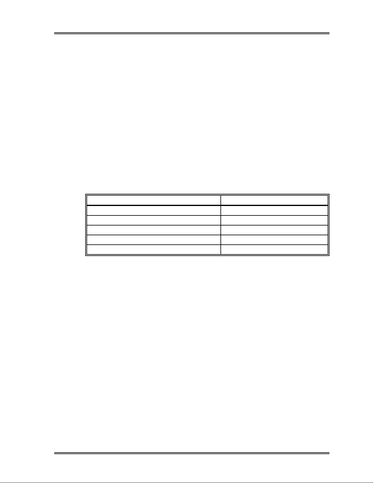
2. START-UP PROCEDURE
2.1 Operator Checks
1 . Reagents
Make sure that there is a sufficient amount of reagent for the day's samples.
If the amount is insufficient, prepare replacement reagent. If reagent runs out
during an analysis, the system automatically stops and alerts the operator to replace
the reagent. Analysis cannot be resumed until replacement is complete. Replace
the reagent container by referring to the procedures in Chapter 5: Maintenance and
Supplies.
The following shows the approximate number of cycles that can be analyzed per
container of reagent.
Table 2-2: Cycles Analyzed per Reagent Container
Reagent Number of Cycles Analyzed
CELLPACK : Diluent 380 cycles per 20 L container
STROMATOLYSER-FB : BASO Reagent 2,500 cycles per 5 L container
STROMATOLYSER-FD (I) : 4Diff Reagent 2,500 cycles per 5 L container
STROMATOLYSER-FD (II) : 4Diff Reagent 2,500 cycles per 500 mL bottle
SULFOLYSER : HGB Reagent 1,000 cycles per 500 mL bottle
SAMPLE PROCESSING
2 . Printer Paper
Make sure that there is sufficient printer paper for the day's samples.
3 . Equipment
Check the tubing and cables. Make sure that the tubing is not bent and the power
cord is securely plugged into the power outlet.
4 . Sampler
Make sure that there are no racks on the analysis line. Remove any rack from the
line. Make sure that the left and right rack pools and analysis line are clear.
5 . Waste Fluid
Discharge any waste fluid that has been collected in the pneumatic unit drain trap
and waste container (if applicable).
Sysmex SF-3000 Operator's Manual -- Revised September 1995 2-3
Page 42
SAMPLE PROCESSING, Start-Up Procedure
2.2 Turning On the Power
Turn ON the power switches in the following order: 1) Printers, 2) Pneumatic Unit and
3) Main Unit. The message "Please Wait" will be displayed on the LCD after
approximately 10 seconds. The pressure and vacuum will reach their preset values
approximately 30 seconds after the power is turned ON.
CAUTION: • If the Data Printer (DP-510) is connected, turn ON the power switch
of the Main Unit first, then the DP-510.
NOTE: • The power of the Pneumatic Unit is controlled by the Main Unit; thus,
you can normally leave the Pneumatic Unit power switch ON.
2 . 3 Self-Checks
The instrument performs a self-check operation automatically after the power is turned
ON. The following checks are performed in order: microprocessor check, program
loading, temperature/pneumatic check, mechanical parts check, and background check.
If any failure occurs during the self-check process, see Chapter 8: Troubleshooting.
1 . Microprocessor Check and Program Loading
When the power is turned on, the message "System test in progress. Wait for a
moment..." will be displayed and the microprocessor performs system and
memory tests automatically. If any error occurs during the self-check, an error
message appears on the screen. Jot down the message and turn the power OFF
and ON again. If the same error message appears, contact a Sysmex service
representative.
When the microprocessor check is completed, the system program will be
automatically loaded from the hard disk. The message "Now Loading System.
Wait for a moment..." is displayed during the program loading.
NOTE: If the Main Unit is powered OFF during the system hard disk is being
accessed ("HD" indicator appears in the System Status Area), the
system memory check will be performed after program loading when
the system is started next time. The message "Verifying stored data.
Please wait..." will appear. It will take approx. 15 minutes to complete
the memory check.
2 . Temperature/Pressure Check
After the program loading is completed, the messages "Running" and "Start-up"
will be displayed on the LCD. The pressure and vacuum are monitored until they
reach the preset range. At the same time, the program advances to the temperature
check and the temperature of the WBC analysis system is checked. Wait until
pressure, vacuum and temperature have reached the allowable range and the
message disappears.
If the message is still displayed 30 minutes after the power has been turned ON, the
instrument is probably malfunctioning. In this case, turn OFF the power and
contact a Sysmex service representative.
2-4 Sysmex SF-3000 Operator's Manual -- Revised July 1998
Page 43
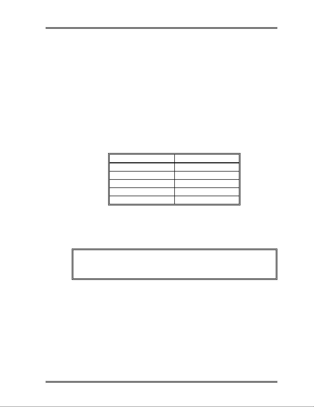
SAMPLE PROCESSING, Start-Up Procedure
3 . Mechanical Parts Check
After the temperature and pressure/vacuum checks are completed, the following
functions will be checked.
• Sampling valve operation
• Whole blood aspiration motor and sheath motor operation
• Whole blood manual aspiration pipette rinsing
4 . Background Check
After the mechanical parts check is completed, the message "Auto Rinse" appears.
After an auto rinse cycle is completed, the background values are checked. If the
background values are less than or equal to those shown in the table below, the
background check is complete.
Table 2-3: Acceptable Background Limits
Parameters Acceptable Limits
WBC/BASO Channel 0.1 [x 103/µL]
DIFF Channel 0.1 [x 103/µL]
RBC 0.02 [x 106/µL]
HGB 0.1 [g/dL]
PLT 1 0 [x 103/µL]
If any of the limits are exceeded, the background check is repeated again. A
maximum of two additional rinse cycles will be performed. If any parameter
exceeds the acceptable limit in both the second and third checks, the background
check stops, the message "Background Error" appears with the corresponding
parameter name, and the alarm sounds.
NOTE: The parameter which the background data exceeded the
acceptable limit is shown in the Status Display. Press [Status]
keypad in the root menu.
In the case of a background error, analysis can be performed; however, the
measured values may be somewhat high. Press [More] key to display the
[Auto Rinse] key. Press the [Auto Rinse] key to perform a background check
again. If the parameters are still not within the acceptable range, see Chapter 8,
Troubleshooting.
Sysmex SF-3000 Operator's Manual -- Revised September 1995 2-5
Page 44

SAMPLE PROCESSING, Start-Up Procedure
2.4 Pressure Gauge Check
The pressure and vacuum gauges should reach their specified levels approximately 30
seconds after the power is turned ON. Confirm that the gauges indicate the values
shown below. If they do not, adjust to the acceptable range.
Table 2-4:
Required Pressure and Vacuum
Pressure 1.8 kg/cm2 or higher
Vacuum 400 mmHg or higher
Pressure
Gauge
Vacuum
Gauge
Figure 2-1: Pressure and Vacuum
Gauges
(Pneumatic Unit - Front)
2.5 Auto Output Settings Check
If Auto Output to the peripheral printer(s) and/or a host computer is desired, before
starting analysis, make sure that the instrument is set to automatically transmit/print. See
Chapter 11: System Setup.
2-6 Sysmex SF-3000 Operator's Manual -- Revised July 1998
Sysmex SF-3000 Operator’s Manual - - Revised September 1995
Page 45

SAMPLE PROCESSING
3. QUALITY CONTROL ANALYSIS
Control samples (SF CHECK) are analyzed and the data is stored in the X or L-J
quality control file. Follow the manufacturer's instructions for handling control material.
Quality control analysis data is stored in specifically designated QC files. For details see
Chapter 6: Quality Control.
NOTE: Using the X Control method, the control sample is analyzed twice
in succession and the average data point is used. The L-J Control
method, on the other hand, uses the result from one analysis as one
control data point.
3.1 QC Analysis: Manual Mode
Follow the procedure below to perform QC analysis in Manual mode. The instrument
will be in Manual mode after the power is turned ON.
(1) Make sure that the READY LED is lit in green.
(2) Press the Next No. keypad in the top line of the LCD. The Sample No. Setting
screen shown below will appear.
Sysmex
Ready
DP:1234567890123
Manual Mode Next No.1234567890123
XM HC GP DP SU
Analysis Mode
Manual Sample Number
1234567890123
Manual Mode
Capillary Mode
Closed Mode
7
4
1
0
C
Sampler
8
5
2
Ð
QC
9
6
3
ENTER
CANCEL
Figure 2-2: Sample No. Setting Screen
(3) The selected analysis mode is backlit in light-blue. Press [Manual Mode] to select
Manual mode, if needed.
Sysmex SF-3000 Operator's Manual -- Revised September 1995 2-7
Page 46
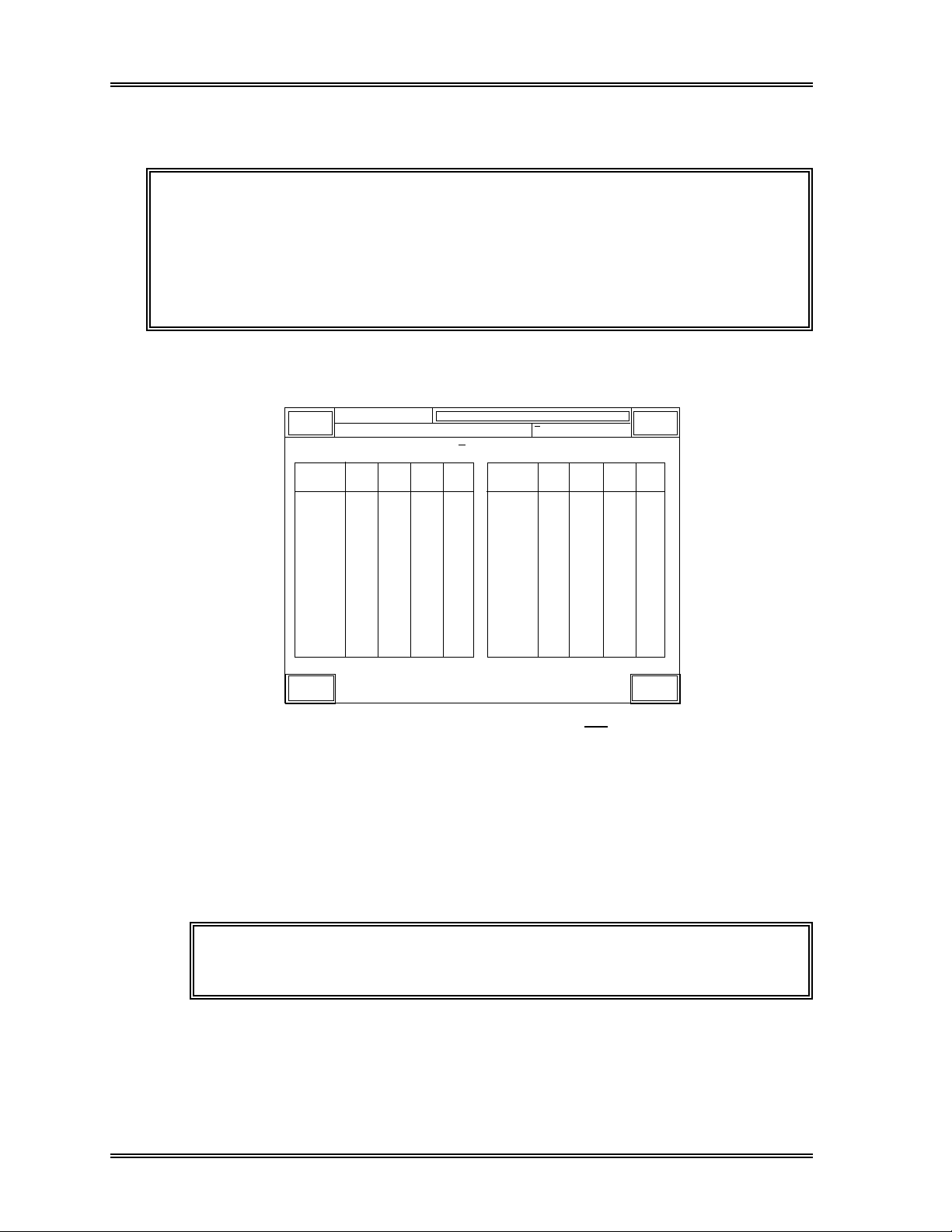
SAMPLE PROCESSING, QC: Manual Mode
(4) Press [QC] key, then specify the file No. using the numerical keypads.
For example to specify the QC file No. 1, press [QC] and [1] keypads.
NOTE: • When SF CHECK is used, files 1 through 12 can be designated.
• The QC file No. is displayed in two digits. For instance when
pressing [QC] and [1], the file No. will be displayed as "QC01".
• Use "QC" - "Target/Limit" - "Lot Info." program to verify that the control
lot number, expiration date, analysis mode (Manual) and necessary
information are set for the specified QC file. Refer to
Section 6.6: Lot Information
for the procedure.
Chapter 6,
(5) Press the [ENTER] key. The QC file No. is specified and the QC Data Display for
the specified file will appear as shown below.
Ready
Sysmex
DP:1234567890123
QC01 < X Control >
X1 X2
WBC
RBC
HGB
HCT
MCV
MCH
MCHC
RDW-SD
RDW-CV
PLT
PDW
MPV
P-LCR
Graphic Return
Manual Mode Next No. QC01-1
Judg-
Mean
ment
NEUT#
LYMPH#
MONO#
EO#
BASO#
NEUT%
LYMPH%
MONO%
EO%
BASO%
GRAN-X
GRAN-Y
WBC/BA-X
WBC/BA-Y
GRAN-Y(W)
XM HC GP DP SU
Sampler
Judg-
MeanX2X1
ment
Figure 2-3: QC Data Display Screen ( X Control)
(6) To analyze the control material in the Manual mode, see Section 4.1: Manual Mode
in this chapter.
(7) After the analysis is completed, the results are displayed.
When the [Return] key is pressed, the program ends and the control data is
automatically accepted and plotted.
NOTE: Press the [Graphic] key on the QC Data Display screen to
display the graphic display.
2-8 Sysmex SF-3000 Operator's Manual -- Revised December 1995
Page 47

SAMPLE PROCESSING, QC: Manual Mode
• When X Control program is used:
The results of the first analysis are displayed in the "X1" column when completed
as shown in Figure 2-4. The sample No. on the graphic screen is shown, for
example, as "QC01-1".
Ready
Sysmex
DP:1234567890123
QC01 < X Control >
X1 X2
WBC
RBC
HGB
HCT
MCV
MCH
MCHC
RDW-SD
RDW-CV
PLT
PDW
MPV
P-LCR
Graphic Return
7.25
4.79
14.0
41.2
87.5
29.8
33.3
46.0
15.3
214
9.8
10.0
23.7
Manual Mode Next No. QC01-2
Judg-
Mean
ment
NEUT#
LYMPH#
MONO#
EO#
BASO#
NEUT%
LYMPH%
MONO%
EO%
BASO%
GRAN-X
GRAN-Y
WBC/BA-X
WBC/BA-Y
GRAN-Y(W)
XM HC GP DP SU
4.63
1.54
0.75
0.17
0.16
63.9
21.2
10.3
2.4
2.2
177.4
177.3
44.2
94.8
43.0
Sampler
Judg-
MeanX2X1
ment
Figure 2-4: "X1" Data Display (Manual Mode)
NOTE: If the results of the first analysis are not acceptable, re-enter the
QC file No. as "QC01-1" and re-analyze the control. The data
in the "X1" column will be replaced with the newly obtained
results, and the new data will be handled as the X
data.
Control first
When the second analysis is completed, the results are displayed in "X2" column.
Then, the mean (average) values of the first and the second analysis results will be
displayed in the "Mean" column. Refer to Figure 2-5a. The sample No. on the
graphic screen is indicated as "QC01" (see Figure 2-5b).
NOTE: Two analysis results obtained consecutively without any
abnormality are used for the X
Sysmex SF-3000 Operator's Manual -- Revised December 1995 2-9
Control.
Page 48
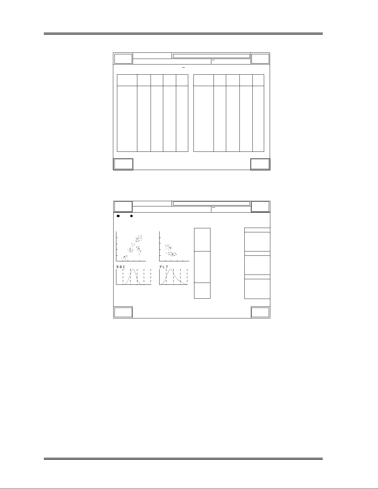
SAMPLE PROCESSING, QC: Manual Mode
Sysmex
Ready
DP:1234567890123
Manual Mode Next No. 1234567890123
XM HC GP DP SU
Sampler
QC01 < X Control >
WBC
RBC
HGB
HCT
MCV
MCH
MCHC
RDW-SD
RDW-CV
PLT
PDW
MPV
P-LCR
X1 X2
7.21
7.25
4.69
4.79
14.1
14.0
42.0
41.2
88.1
87.5
29.6
29.8
34.5
33.3
46.8
46.0
16.1
15.3
214
9.8
10.6
10.0
24.9
23.7
212
9.8
Mean
7.23
4.74
14.1
41.6
87.8
29.7
33.9
46.4
15.7
213
9.8
10.3
24.3
Judgment
NEUT#
LYMPH#
MONO#
EO#
BASO#
NEUT%
LYMPH%
MONO%
EO%
BASO%
GRAN-X
GRAN-Y
WBC/BA-X
WBC/BA-Y
GRAN-Y(W)
4.63
1.54
0.75
0.17
0.16
63.9
21.2
10.3
2.4
2.2
177.4
177.3
44.2
94.8
43.0
4.61
1.56
0.67
0.18
0.19
63.9
21.6
177.4
177.1
44.1
94.6
43.0
9.3
2.5
2.6
MeanX2X1
4.62
1.55
0.71
0.18
0.17
63.9
21.4
9.8
2.5
2.4
177.4
177.2
44.2
94.7
43.0
Judgment
Graphic Return
Figure 2-5a: QC Data Display Screen (Manual Mode)
Sysmex
Ready
DP:1234567890123
Manual Mode
Last
QC01
NO.
D I F F W B C / B A S O
R B C P L T
250fL 40fL
Next No.1234567890123
HC GP DP S U
XM
7.23
WBC
4.62
NEUT
1.55
LYMPH
0.71
MONO
0.18
EO
BASO
0.17
4.74
RBC
HGB
14.1
HCT
41.6
MCV
87.8
MCH
29.7
MCHC
33.9
RDW-SD
46.4
RDW-CV
15.7
213
PLT
PDW
MPV
P-LCR
9.8
10.3
24.3
3
[x10 /uL]
[%]
63.9
[%]
21.4
[%]
9.8
[%]
2.5
[%]
2.4
6
[x10 /uL]
[g/dL]
[%]
[fL]
[pg]
[g/dL]
[fL]
[%]
3
[x10 /uL]
[fL]
[fL]
[%]
Sampler
R:0000-00 15:48 1996/6/30
WBC Flag
RBC Flag
PLT Flag
QC Data Return
Figure 2-5b: Control Data Graphic Display (Manual Mode)
2-10 Sysmex SF-3000 Operator's Manual -- Revised December 1995
Page 49

SAMPLE PROCESSING, QC: Manual Mode
• When L-J Control program is used:
The QC analysis results are displayed as shown in Figure 2-6. The sample No. on
the graphic display is indicated as "QC01".
Ready
Sysmex
DP:1234567890123
QC01 < L-J Control >
WBC
RBC
HGB
HCT
MCV
MCH
MCHC
RDW-SD
RDW-CV
PLT
PDW
MPV
P-LCR
Graphic Return
7.23
4.74
14.1
41.6
87.8
29.7
33.9
46.4
15.7
213
10.3
24.3
9.8
Manual Mode Next No. 1234567890123
XM HC GP DP SU
JudgmentData
NEUT#
LYMPH#
MONO#
EO#
BASO#
NEUT%
LYMPH%
MONO%
EO%
BASO%
GRAN-X
GRAN-Y
WBC/BA-X
WBC/BA-Y
GRAN-Y(W)
4.62
1.55
0.71
0.18
0.17
63.9
21.4
9.8
2.5
2.4
177.4
177.2
44.2
94.7
43.0
Sampler
JudgmentData
Figure 2-6: QC Data Display Screen (L-J Control)
NOTE: If the displayed results are not acceptable, re-enter the QC File
No. as "QC01" and re-analyze the control. The data in the
"Data" column will be replaced with the newly obtained results,
and the new data will be handled as the L-J Control data.
If the error message < X Limit Error> or <L-J Limit Error> appears in the system status
area (upper portion of the LCD), the analyzed data has exceeded the control limit.
The "+" or "-" sign in yellow backlight will be displayed in the "Judgment" column and
the "Check Control Chart" message window appears. On the graphic display, the "+" or
"-" sign in yellow backlight will also be added to the parameter which is outside the
control limits. Check the control chart and review the control data. Reanalyze the
sample, if needed. Refer to Chapter 6: Quality Control.
When the message "Reanalyze Control" appears, the analyzed data is more than 3 times
the limit and will not be recorded in memory. The "+" or "-" sign in red backlight will be
displayed in the "Judgment" column. On the graphic display, the "+" or "-" sign in red
backlight will also be added to the parameter which is outside the control limits.
Reanalyze the sample.
If an analysis error occurs during QC analysis, the error message <QC Analysis Error>
will be displayed. The results are not plotted as a control data point. Reanalyze the
sample.
Sysmex SF-3000 Operator's Manual -- Revised December 1995 2-11
Page 50

SAMPLE PROCESSING
3.2 QC Analysis: Auto Mode
Execute L-J can be performed in auto (sampler) mode if SF CHECK is used. Follow the
procedure below to execute quality control analyses in auto mode.
NOTE: X Control cannot be performed in Auto mode.
(1) Check the volume of control material.
Required sample volume: 1.0 mL or more
Aspirated sample volume: 270 µL
NOTE: When SF CHECK is used, files 1 through 12 can be designated in
advance.
(2) Use the Lot Information of Target/Limit submenu to verify the control lot
information for the control file to be used. See Chapter 6: Quality Control for the
procedures.
(3) To analyze the control material in the auto mode, see Section 4.3: Auto Mode in
this chapter. After analysis is completed, the results are recorded in the file
designated by the bar code.
NOTE: The QC Data Display screen as shown in Figure 2-6 on the previous
page will not be displayed for the QC analysis in Auto mode.
When the "Check Control Chart" message window appears, the analyzed data has
exceeded the control limit. Check the control chart and review the control data.
See Chapter 6: Quality Control for QC chart review information.
When the message "Reanalyze Control" appears, the analyzed data is more than 3
times the limit and will not be recorded in memory. Reanalyze the sample.
NOTE: The expiration date of SF CHECK is monitored if the expiration date
information is entered in the control file. "Control Expired" will be
reported when SF CHECK is analyzed and the lot has already been
expired. The analyzed data will not be plotted on the QC chart.
Refer to Chapter 6, Section 9: Sampler QC Analysis for further information.
2-12 Sysmex SF-3000 Operator's Manual -- Revised December 1995
Page 51

SAMPLE PROCESSING
3.3 QC Analysis: Manual Closed Mode
QC analyses can be performed in Manual Closed mode if the sampler unit is installed and
SF CHECK is used. Follow the procedure below to execute quality control analyses in
Closed mode.
(1) Make sure that the READY LED is lit.
(2) Press the Next No. keypad in the top line of the LCD. The Sample No. Setting
screen will appear.
(3) The selected analysis mode is backlit in light-blue. Press [Closed Mode] to select
Closed mode, if needed.
Sysmex
Ready
DP:1234567890123
Closed Mode Next No.1234567890123
XM HC GP DP SU
Analysis Mode
Closed Sample Number
1234567890123
Manual Mode
Capillary Mode
Closed Mode
7
4
1
0
C
Sampler
8
5
2
Ð
Q C
9
6
3
ENTER
CANCEL
Figure 2-7: Sample No. Setting Screen (Closed Mode)
(4) Press [QC] key, then specify the file No. using the numerical keypads.
For example to specify the QC file No. 3, press the [QC] and the [3] keypad.
NOTE: • When SF CHECK is used, files 1 through 12 can be designated.
• The QC file No. is displayed in two digits. For instance when
pressing [QC] and [3], the file No. will be displayed as "QC03".
• Use "QC" - "Target/Limit" - "Lot Info." program to verify that the control
lot number, expiration date, analysis mode (Closed) and necessary
information are set for the specified QC file. Refer to
Section 6.6: Lot Information
for the procedure.
Chapter 6,
(5) Press the [ENTER] key. The QC file No. is specified and the QC Data Display will
appear as shown in Figure 2-8.
Sysmex SF-3000 Operator's Manual -- Revised December 1995 2-13
Page 52

SAMPLE PROCESSING, QC: Manual Closed Mode
Ready
Sysmex
DP:1234567890123
QC03 < X Control >
X1 X2
WBC
RBC
HGB
HCT
MCV
MCH
MCHC
RDW-SD
RDW-CV
PLT
PDW
MPV
P-LCR
Graphic Return
Closed Mode Next No. QC03-1
Judg-
Mean
ment
NEUT#
LYMPH#
MONO#
EO#
BASO#
NEUT%
LYMPH%
MONO%
EO%
BASO%
GRAN-X
GRAN-Y
WBC/BA-X
WBC/BA-Y
GRAN-Y(W)
XM HC GP DP SU
Sampler
Judg-
MeanX2X1
ment
Figure 2-8: QC Data Display Screen ( X Control)
(6) To analyze the control material in the Manual Closed mode, see Section 4.4:
Manual Closed Mode in this chapter.
(7) After the analysis is completed, the results are displayed.
When the [Return] key is pressed, the program ends and the control data is
automatically accepted and plotted.
NOTE: Press the [Graphic] key on the QC Data Display screen to
display the graphic display.
• When X Control program is used:
The results of the first analysis are displayed in the "X1" column when completed.
The sample No. on the graphic screen is shown, for example, as "QC03-1".
Ready
Sysmex
DP:1234567890123
QC03 < X Control >
X1 X2
WBC
RBC
HGB
HCT
MCV
MCH
MCHC
RDW-SD
RDW-CV
PLT
PDW
MPV
P-LCR
Graphic Return
7.25
4.79
14.0
41.2
87.5
29.8
33.3
46.0
15.3
214
9.8
10.0
23.7
Closed Mode Next No. QC03-2
Judg-
Mean
ment
NEUT#
LYMPH#
MONO#
EO#
BASO#
NEUT%
LYMPH%
MONO%
EO%
BASO%
GRAN-X
GRAN-Y
WBC/BA-X
WBC/BA-Y
GRAN-Y(W)
XM HC GP DP SU
4.63
1.54
0.75
0.17
0.16
63.9
21.2
10.3
2.4
2.2
177.4
177.3
44.2
94.8
43.0
Sampler
Judg-
MeanX2X1
ment
Figure 2-9a: "X1" Data Display (Closed Mode)
2-14 Sysmex SF-3000 Operator's Manual -- Revised December 1995
Page 53

SAMPLE PROCESSING, QC: Manual Closed Mode
NOTE: If the results of the first analysis are not acceptable, re-enter the
QC file No. as "QC03-1" and re-analyze the control. The data
in the "X1" column will be replaced with the newly obtained
results, and the new data will be handled as the X
Control first
data.
When the second analysis is completed, the results are displayed in "X2" column.
Then, the mean (average) values of the first and the second analysis results will be
displayed in the "Mean" column. Refer to Figure 2-9b. The sample No. on the
graphic screen is indicated as "QC03" (see Figure 2-9c).
NOTE: Two analysis results obtained consecutively without any
abnormality are used for the X
Control.
Ready
Sysmex
DP:1234567890123
QC03 < X Control >
X1 X2
WBC
RBC
HGB
HCT
MCV
MCH
MCHC
RDW-SD
RDW-CV
PLT
PDW
MPV
P-LCR
Graphic Return
7.25
4.79
14.0
41.2
87.5
29.8
33.3
46.0
15.3
214
9.8
10.0
23.7
7.21
4.69
14.1
42.0
88.1
29.6
34.5
46.8
16.1
212
10.6
24.9
Closed Mode Next No. 1234567890123
Judg-
Mean
ment
9.8
7.23
4.74
14.1
41.6
87.8
29.7
33.9
46.4
15.7
213
9.8
10.3
24.3
NEUT#
LYMPH#
MONO#
EO#
BASO#
NEUT%
LYMPH%
MONO%
EO%
BASO%
GRAN-X
GRAN-Y
WBC/BA-X
WBC/BA-Y
GRAN-Y(W)
XM HC GP DP SU
4.63
4.61
1.54
1.56
0.75
0.67
0.17
0.18
0.16
0.19
63.9
63.9
21.2
21.6
10.3
9.3
2.4
2.5
2.2
2.6
177.4
177.4
177.3
177.1
44.2
44.1
94.8
94.6
43.0
43.0
MeanX2X1
4.62
1.55
0.71
0.18
0.17
63.9
21.4
9.8
2.5
2.4
177.4
177.2
44.2
94.7
43.0
Sampler
Judgment
Figure 2-9b: QC Data Display Screen (Closed Mode)
Sysmex SF-3000 Operator's Manual -- Revised December 1995 2-15
Page 54

SAMPLE PROCESSING, QC: Manual Closed Mode
Ready
Sysmex
DP:1234567890123
Last
D I F F W B C / B A S O
R B C P L T
250fL 40fL
QC Data Return
Closed Mode
P QC03
NO.
Next No.1234567890123
HC GP DP S U
XM
7.23
WBC
4.62
NEUT
1.55
LYMPH
0.71
MONO
0.18
EO
BASO
0.17
4.74
RBC
HGB
14.1
HCT
41.6
MCV
87.8
MCH
29.7
MCHC
33.9
RDW-SD
46.4
RDW-CV
15.7
213
PLT
PDW
MPV
P-LCR
9.8
10.3
24.3
3
[x10 /uL]
63.9
[%]
[%]
21.4
9.8
[%]
2.5
[%]
2.4
[%]
6
[x10 /uL]
[g/dL]
[%]
[fL]
[pg]
[g/dL]
[fL]
[%]
3
[x10 /uL]
[fL]
[fL]
[%]
Sampler
R:0000-00 15:48 1996/6/30
WBC Flag
RBC Flag
PLT Flag
Figure 2-9c: Control Data Graphic Display (Closed Mode)
• When L-J Control program is used:
The QC analysis results are displayed as shown in Figure 2-10. The sample No.
on the graphic display is indicated as "QC03".
Ready
Sysmex
DP:1234567890123
QC03 < L-J Control >
Closed Mode Next No. 1234567890123
XM HC GP DP SU
Sampler
JudgmentData
WBC
RBC
HGB
HCT
MCV
MCH
MCHC
RDW-SD
RDW-CV
PLT
PDW
MPV
P-LCR
Graphic Return
7.23
4.74
14.1
41.6
87.8
29.7
33.9
46.4
15.7
213
10.3
24.3
9.8
NEUT#
LYMPH#
MONO#
EO#
BASO#
NEUT%
LYMPH%
MONO%
EO%
BASO%
GRAN-X
GRAN-Y
WBC/BA-X
WBC/BA-Y
GRAN-Y(W)
4.62
1.55
0.71
0.18
0.17
63.9
21.4
177.4
177.2
44.2
94.7
43.0
9.8
2.5
2.4
JudgmentData
Figure 2-10: QC Data Display Screen (L-J Control)
NOTE: If the displayed results are not acceptable, re-enter the QC File
No. as "QC03" and re-analyze the control. The data in the
"Data" column will be replaced with the newly obtained results,
and the new data will be handled as the L-J Control data.
2-16 Sysmex SF-3000 Operator's Manual -- Revised December 1995
Page 55

SAMPLE PROCESSING, QC: Manual Closed Mode
If the error message < X Limit Error> or <L-J Limit Error> appears in the system status
area (upper portion of the LCD), the analyzed data has exceeded the control limit.
The "+" or "-" sign in yellow backlight will be displayed in the "Judgment" column and
the "Check Control Chart" message window appears. On the graphic display, the "+" or
"-" sign in yellow backlight will also be added to the parameter which is outside the
control limits. Check the control chart and review the control data. Reanalyze the
sample, if needed. Refer to Chapter 6: Quality Control.
When the message "Reanalyze Control" appears, the analyzed data is more than 3 times
the limit and will not be recorded in memory. The "+" or "-" sign in red backlight will be
displayed in the "Judgment" column. On the graphic display, the "+" or "-" sign in red
backlight will also be added to the parameter which is outside the control limits.
Reanalyze the sample.
If an analysis error occurs during QC analysis, the error message <QC Analysis Error>
will be displayed. The results are not plotted as a control data point. Reanalyze the
sample.
3. 4 QC Analysis: Manual CP Mode
QC analyses can be performed in Manual Closed mode if the Manual CP Unit is installed
and SF CHECK is used. Follow the procedure below to execute quality control analyses
in Manual CP mode.
The procedures to select the Closed mode, to select QC file and the results displays are
the same as those in the Manual Closed mode. Refer to the previous Section 3.3: QC
Analysis: Manual Closed Mode for the detailed procedures.
To analyze the control material in the Manual CP mode, see Section 4.5: Manual CP
Mode in this chapter.
Sysmex SF-3000 Operator's Manual -- Revised December 1995 2-17
Page 56

SAMPLE PROCESSING
4. ANALYSIS MODE PROCEDURES
4. 1 Manual Mode
Manual mode operation can be performed when the system is in the READY mode.
Operation in this mode requires the operator to mix, uncap the sample, and manually
introduce the specimen to the analyzer.
Analysis of the sample is performed in the following steps:
1. Collect and prepare sample
2. Select Manual mode
3. Input sample ID number
4. Analyze sample
5. Display analysis results
6. Output analysis results
7. Perform post-analysis procedures
1 . Collect and Prepare Sample
Draw the specified amount of blood (corresponding to the amount of EDTA
anticoagulant).
CAUTION: • Some anticoagulants will alter test results due to their effects on
hemolysis and blood platelet agglutination. Therefore, use K
EDTA, K3 EDTA, or Na2 EDTA as the anticoagulant.
• Samples must be warmed to room temperature for approximately 30
minutes before analysis.
2
The height of the blood sample tube should be 75 mm or shorter. Sample volumes are
shown below.
Aspirated sample volume: Approx. 170 µL
2-18 Sysmex SF-3000 Operator's Manual -- Revised September 1995
Page 57

SAMPLE PROCESSING, Manual Mode Procedures
2 . Select Manual Mode
If "Manual Mode" does not appear on the LCD display, follow the procedure below to
select Manual mode.
(1) Press the Next No. keypad in the top line of the LCD. The Sample No. Setting
screen shown below will appear.
Sysmex
Ready
DP:1234567890123
Closed Mode Next No.1234567890123
XM HC GP DP SU
Analysis Mode
Manual Sample Number
1234567890123
Manual Mode
Capillary Mode
Closed Mode
7
4
1
0
C
Sampler
8
5
2
Ð
QC
9
6
3
ENTER
CANCEL
Figure 2-11: Sample No. Setting Screen (Manual Mode)
(2) The selected analysis mode is backlit in light-blue. Press [Manual Mode] to select
Manual mode.
3 . Input Sample ID Number
Using the Sample No. Setting Screen, input the next sample ID number to be analyzed as
described below, if needed.
(1) The next sample number to the previously analyzed sample in Manual mode
appears above the numerical keys. Clear the number by pressing [C] key and input
the sample ID number with the numerical keys, if needed.
NOTE: When the next sample No. is not set, or after the power ON, the next
sample No. is automatically set to No. 1, increasing by 1 for each
succeeding sample (e.g.
, 1, 2, 3, ...).
(2) Press [ENTER]. The next sample No. is set and the Sample No. Setting screen
will disappear. The input sample No. will be displayed in the Next No. column in
the top line of the LCD.
Sysmex SF-3000 Operator's Manual -- Revised September 1995 2-19
Page 58
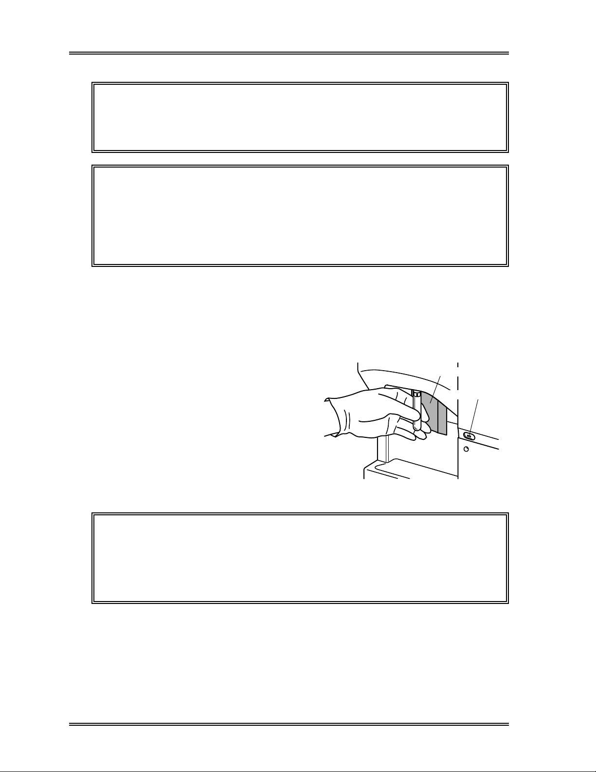
SAMPLE PROCESSING, Manual Mode Procedures
CAUTION: Do not use zero as the sample ID number. If the ID number is set to
zero, the analysis results will neither be stored nor output. If the
sample I
during sample aspiration to alert the operator.
NOTE: • The sample ID can include numbers (0-9) and hyphens up to a
maximum of 13 characters.
• Hyphens cannot be placed at the beginning or end of the sample ID
number, nor can two hyphens be placed consecutively.
• A number will not be carried beyond a hyphen. For example, the
number following 2-999 will be 2-000; 1-99-000 will follow 1-99-999.
• The number following 9999999999999 will be 1.
D number is set to zero, continuous short beeps will sound
4 . Analyze Sample
(1) Mix the whole blood sample thoroughly by inverting the tube.
(2) Remove the cap carefully so as not to splatter blood.
(3) Set the sample tube into the manual
aspiration pipette as shown in the
figure; then press the Start Switch. Do
not remove the sample tube while the
START Switch
READY LED
READY LED is blinking; sample is
being aspirated.
(4) After the READY LED turns off (and
beep sounds three times), remove the
sample tube.
Figure 2-12: Introduce Sample
CAUTION: • You must remove the sample tube within 5 seconds after the
READY LED turns off, because the manual rinse cup moves down.
• To remove the sample, pull straight down to prevent bending the
manual aspiration pipette.
• The manual aspiration pipette is automatically rinsed, and does not
need to be wiped manually.
2-20 Sysmex SF-3000 Operator's Manual -- Revised September 1995
Page 59
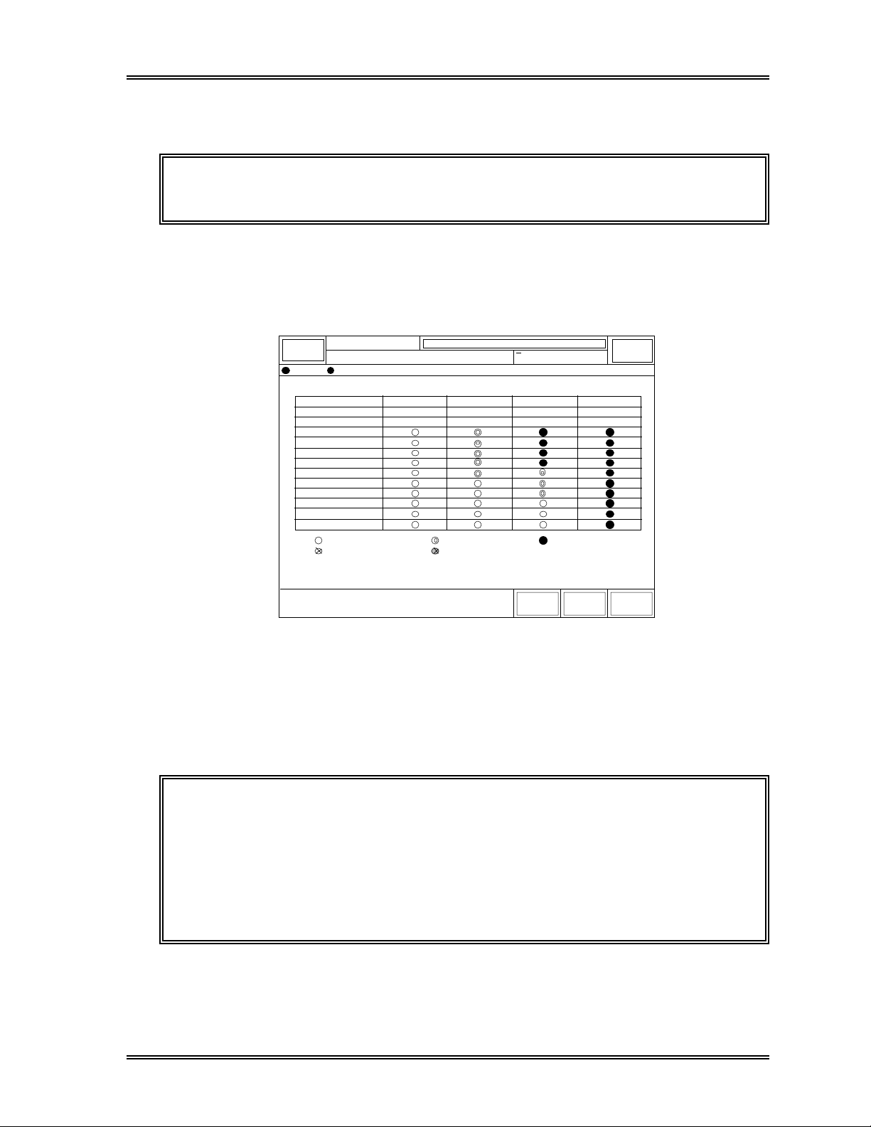
SAMPLE PROCESSING, Manual Mode Procedures
(5) When the READY LED turns on again, "Sample Asp Ready" message is
displayed. Prepare the next sample and repeat steps (1)-(4).
NOTE: If sample ID numbers are not set, they are automatically assigned
sequentially.
After the sample is aspirated, the analysis begins. You can check the status of each stage
of analysis using the Analysis Process screen. To see this screen, press [Status] key in
the root menu. Switch to "P2. Analysis Process" using the [→] and [←] keys.
Ready
Sysmex
DP:1234567890123
STATUS
Sequence
ID No.
Rack
Aspirate
Dilute
RBC Count
WBC/BASO Count
DIFF Count
RBC Analyze
WBC/BASO Analyze
DIFF Analyze
Edit
Store
: Entry
: Interruption
Manual Mode Next No.1234567890123
< Analysis Process >
13
123-567-90123
0000-00
12
123-567-90122
0000-00
: Run
: Finish Abnormal
XM HC GP DP SU
11
123-567-90121
0000-00
: Finish Normal
←
Sampler
10
123-567-90120
0000-00
→ Return
Figure 2-13: Analysis Process Screen (Manual Mode)
5 . Display Analysis Results
After analysis is completed (approximately 85 seconds after the sample is aspirated), the
results are displayed on the screen.
CAUTION: If all the following conditions are met, the sample is assumed blank and
the analysis result will neither be stored nor judged against any
flagging criteria.
WBC < 1.00 x 10
RBC < 0.30 x 10
3
6
/µL
/µL
HGB < 1.0 g/dL
PLT < 20 x 10
Sysmex SF-3000 Operator's Manual -- Revised September 1995 2-21
3
/µL
Page 60

SAMPLE PROCESSING, Manual Mode Procedures
Stored
Data
Manual Mode
12345
NO.
QC
Next No.1234567890123
XM
HC GP D P SU
WBC
7.23
NEUT
4.62
LYMPH
1.55
MONO
0.71
EO
0.18
BASO
0.17
RBC
4.74
HGB
14.1
HCT
41.6
MCV
87.8
MCH
MCHC
RDW-SD
RDW-CV
PLT
PDW
MPV
P-LCR
GP
Print
29.7
33.9
46.4
15.7
213
9.8
10.3
24.3
Print
DP
15:48 1996/6/30
3
[x10 /uL]
63.9
21.4
9.8
2.5
2.4
6
[x10 /uL]
[g/dL]
[%]
[fL]
[pg]
[g/dL]
[fL]
[%]
3
[x10 /uL]
[fL]
[fL]
[%]
Replace
Reagent
[%]
[%]
[%]
[%]
[%]
Sampler
R:0000-00
WBC Flag
RBC Flag
PLT Flag
Return
Ready
Sysmex
DP:1234567890123
Last
D I F F W B C / B A S O
R B C P L T
250fL 40fL
Status
Work
List
Figure 2-14: Analysis Results Screen (Manual Mode)
6 . Output Analysis Results
If automatic output has been set, the analysis results will be sent to the Graphic Printer,
Data Printer, and/or Host Computer.
If automatic output has not been set, the operator must select the data and destination for
the output. See Chapter 4: Result Interpretation/Reports.
7 . Perform Post-Analysis Procedures
Residual blood and reagent can cause detector aperture to clog and protein to build up in
aspiration lines. If the instrument is not to be used for a while, press the [Auto Rinse]
key in the root menu to execute a background check.
NOTE: If the [Auto Rinse] key is not displayed on the LCD, press [More] key
to change the root menu display.
2-22 Sysmex SF-3000 Operator's Manual -- Revised September 1995
Page 61

SAMPLE PROCESSING, Capillary Mode Procedures
4.2 Capillary Mode
Capillary mode operation can be performed when the system is in the READY mode.
Operation in this mode requires the operator to manually dilute, mix, uncap, and
introduce the diluted specimen to the analyzer.
Analysis of the sample is performed in the following steps:
1. Collect and prepare sample
2. Select capillary mode
3. Input sample ID number
4. Prepare 1:5 dilution of sample
5. Analyze sample
6. Display analysis results
7. Output analysis results
8. Perform post-analysis procedures
1 . Collect and Prepare Sample
Using CELLPACK dispensed ahead of time, dilute the sample to a 1:5 ratio.
CAUTION: With blood samples taken from the earlobe or fingertip, generally as
the blood count increases, reproducibility decreases. If possible,
analyze the diluted sample twice, and compare the results. When a
heparin-coated capillary tube or something similar is used,
depending on the anticoagulant, hemolysis or platelet agglutination
occurs; this can alter the analysis results. Use K2 EDTA, K3 EDTA,
or Na
EDTA as the anticoagulant.
2
The height of the blood sample tube should be 75 mm or shorter. Sample volumes are
shown below.
Required sample volume: 40 µL or more
Diluted sample volume aspirated: Approx. 170 µL
Sysmex SF-3000 Operator's Manual -- Revised September 1995 2-23
Page 62
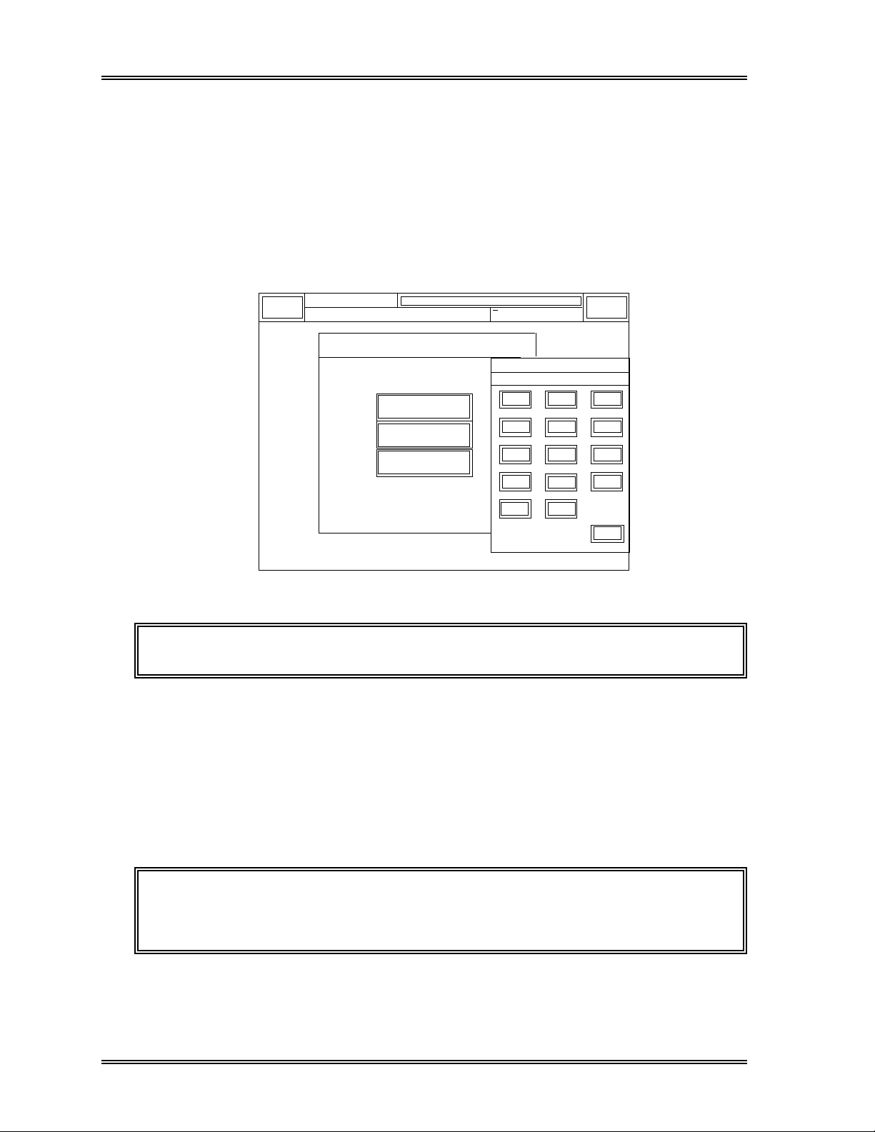
SAMPLE PROCESSING, Capillary Mode Procedures
2 . Select Capillary Mode
If "Capillary Mode" does not appear on the LCD display, follow the procedure below to
select capillary mode.
(1) Press the Next No. keypad in the top line of the LCD. The Sample No. Setting
screen will appear.
(2) The selected analysis mode is backlit in light-blue. Press [Capillary Mode] to select
capillary mode.
Sysmex
Ready
DP:1234567890123
Capillary Mode Next No.1234567890123
XM HC GP DP SU
Analysis Mode
Capillary Sample Number
1234567890123
Manual Mode
Capillary Mode
Closed Mode
7
4
1
0
C
Sampler
8
5
2
Ð
QC
9
6
3
ENTER
CANCEL
Figure 2-15: Sample No. Setting Screen (Capillary Mode)
NOTE: The Next No. keypad is indicated in yellow back light .
3 . Input Sample ID Number
Using the Sample No. Setting Screen, input the next sample ID number to be analyzed as
described below, if needed.
(1) The next sample number to the previously analyzed sample in Capillary mode
appears above the numerical keys. Clear the number by pressing [C] key and input
the sample ID number with the numerical keys, if needed.
NOTE: When the next sample No. is not set, or after the power ON, the next
sample No. is automatically set to No. 1, increasing by 1 for each
succeeding sample (e.g., 1, 2, 3, ...).
2-24 Sysmex SF-3000 Operator's Manual -- Revised September 1995
Page 63
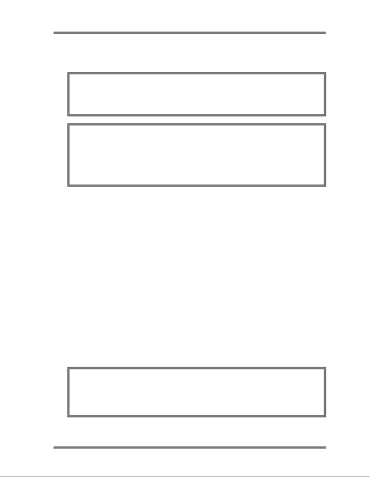
SAMPLE PROCESSING, Capillary Mode Procedures
(2) Press [ENTER]. The next sample No. is set and the Sample No. Setting screen
will disappear. The input sample No. will be displayed in the Next No. column in
the top line of the LCD.
CAUTION: Do not use zero as the sample ID number. If the ID number is set to
zero, the analysis results will neither be stored nor output. If the
sample I
during sample aspiration to alert the operator.
NOTE: • The sample ID can include numbers (0-9) and hyphens up to a
maximum of 13 characters.
• Hyphens cannot be placed at the beginning or end of the sample ID
number, nor can two hyphens be placed consecutively.
• A number will not be carried beyond a hyphen. For example, the
number following 2-999 will be 2-000; 1-99-000 will follow 1-99-999.
• The number following 9999999999999 will be 1.
D number is set to zero, continuous short beeps will sound
4 . Prepare 1:5 Dilution of Sample
Prepare a 1:5 dilution using the following materials:
• Diluent (CELLPACK)
• Microtube (MT-40, etc.)
• 40 µL pipette (40 µL SMI micropettor, mode 1058-D40)
• 160 µL pipette (50 µL-250 µL SMI micropettor, model 1200-J, etc.)
• Diluent dispensing container (beaker, etc.)
• Diluent dispensing equipment (pipettor, etc.)
(1) Rinse a beaker with CELLPACK, to eliminate dust, etc.
(2) Carefully dispense CELLPACK into the beaker with a pipettor.
(3) Carefully transfer 160 µL of CELLPACK from the beaker with a micro pipettor to
the capillary analysis container (e.g. Micro Centrifuge Tube).
(4) Pipette 40 µL of patient blood to the capillary analysis container containing the 160
µL of CELLPACK.
(5) Cap and mix well.
NOTE: Prepare and analyze the 1:5 sample dilution as soon after collection as
possible to minimize platelet agglutination. Also, if diluent is dispensed
ahead of time, measurement errors are generated because of
evaporation and contaminants; therefore, prepare new diluted sample
each time an analysis is performed.
Sysmex SF-3000 Operator's Manual -- Revised September 1995 2-25
Page 64

SAMPLE PROCESSING, Capillary Mode Procedures
5 . Analyze Sample
(1) Mix the capillary sample thoroughly.
(2) Set the sample tube into the manual
aspiration pipette as shown in the
figure; then press the Start Switch. Do
not remove the sample tube while the
START Switch
READY LED
READY LED is blinking; sample is
being aspirated.
(3) After the READY LED turns off (and
beep sounds three times), remove the
sample tube.
Figure 2-16: Introduce Sample
CAUTION: • You must remove the sample tube within 5 seconds after the READY
LED turns off, because the manual rinse cup moves down.
• To remove the sample, pull straight down to prevent bending the
manual aspiration pipette.
• The manual aspiration pipette is automatically rinsed, and does not
need to be wiped manually.
(4) When the READY LED turns on again, "Sample Asp Ready" is displayed. Prepare
the next sample and repeat steps (1)-(3) above.
NOTE: If sample ID numbers are not set, they are automatically assigned
sequentially.
2-26 Sysmex SF-3000 Operator's Manual -- Revised September 1995
Page 65

SAMPLE PROCESSING, Capillary Mode Procedures
After the sample is aspirated, the analysis begins. You can check the status of each stage
of analysis using the Analysis Process screen. To see this screen, press [Status] key in
the root menu. Switch to "P2. Analysis Process" using the [→] and [←] keys.
Ready
Sysmex
DP:1234567890123
STATUS
Sequence
ID No.
Rack
Aspirate
Dilute
RBC Count
WBC/BASO Count
DIFF Count
RBC Analyze
WBC/BASO Analyze
DIFF Analyze
Edit
Store
: Entry
: Interruption
Capillary Mode Next No.1234567890123
< Analysis Process >
13
123-567-90123
0000-00
12
123-567-90122
0000-00
: Run
: Finish Abnormal
XM HC GP DP SU
11
123-567-90121
0000-00
: Finish Normal
←
Sampler
10
123-567-90120
0000-00
→ Return
Figure 2-17: Analysis Process Screen (Capillary Mode)
6 . Display Analysis Results
After analysis is completed (approximately 85 seconds after the sample is aspirated), the
results are displayed on the screen.
NOTE: "C" in green backlight is added to the left of Sample ID No.
Data
Capillary Mode
12345
NO.
C
QC
Next No.1234567890123
XM
HC GP D P SU
GP
Print
7.23
4.62
1.55
0.71
0.18
0.17
4.74
14.1
41.6
87.8
29.7
33.9
46.4
15.7
213
9.8
10.3
24.3
DP
Print
WBC
NEUT
LYMPH
MONO
EO
BASO
RBC
HGB
HCT
MCV
MCH
MCHC
RDW-SD
RDW-CV
PLT
PDW
MPV
P-LCR
15:48 1996/6/30
3
[x10 /uL]
63.9
21.4
9.8
2.5
2.4
6
[x10 /uL]
[g/dL]
[%]
[fL]
[pg]
[g/dL]
[fL]
[%]
3
[x10 /uL]
[fL]
[fL]
[%]
Replace
Reagent
[%]
[%]
[%]
[%]
[%]
Sampler
R:0000-00
WBC Flag
RBC Flag
PLT Flag
Return
Ready
Sysmex
DP:1234567890123
Last
D I F F W B C / B A S O
R B C P L T
250fL 40fL
Status
Work
List
Stored
Sysmex SF-3000 Operator's Manual -- Revised September 1995 2-27
Page 66

SAMPLE PROCESSING, Capillary Mode Procedures
In capillary mode, the following flags are available with the 8 CBC parameters (WBC,
RBC, HGB, HCT, MCV, MCH, MCHC and PLT):
(1) Error function indication
(2) Error limit marks "+" and "–"
(3) Linearity limit mark "*"
(4) POSITIVE flag (no NEGATIVE flag is displayed.)
(5) The following IP messages:
WBC: Leukocytopenia Leukocytosis
RBC:Microcytosis Macrocytosis
Hypochromia Anemia
Erythrocytosis
PLT: Thrombocytopenia Thrombocytosis
Analyzed results other than the 8 CBC parameters are not reported in the capillary mode.
CAUTION: If all the following conditions are met, the sample is assumed blank and
the analysis result will be neither stored nor judged against any
flagging criteria.
WBC < 1.00 x 10
RBC < 0.30 x 10
HGB < 1.0 g/dL
PLT < 20 x 10
3
6
3
/µL
/µL
/µL
7 . Output Analysis Results
If automatic output has been set, the analysis results will be sent to the Graphic Printer,
Data Printer, and/or Host Computer.
If automatic output has not been set, the operator must select the data and destination for
the output. See Chapter 4: Result Interpretation/Reports.
8 . Perform Post-Analysis Procedures
Residual blood and reagent can cause detector aperture to clog and protein to build up in
aspiration lines. If the instrument is not to be used for a while, press the [Auto Rinse]
key in the root menu to execute an auto rinse and a background check.
NOTE: If the [Auto Rinse] key is not displayed on the LCD, press [More] key
to change the root menu display.
If no further capillary specimens require processing, return the system to Manual mode
as follows:
(1) Press the Next No. keypad in the top line of the LCD. The Sample No. Setting
screen will appear.
(2) Press the [Manual Mode] key to select Manual mode, and press the [Enter] key.
2-28 Sysmex SF-3000 Operator's Manual -- Revised September 1995
Page 67

SAMPLE PROCESSING, Auto Mode Procedures
4.3 Auto Mode
Auto (sampler) mode operation can be performed when the system is in the READY
mode. This mode permits automatic mixing, aspiration, and analysis of samples.
Analysis of the sample is performed in the following steps:
1. Collect and prepare sample
2. Input sample ID number
3. Analyze sample
4. Display analysis results
5. Output analysis results
6. Perform post-analysis procedures
1 . Collect and Prepare Sample
(1) Collect sample.
Draw the specified amount of blood (corresponding to the amount of EDTA
anticoagulant).
CAUTION: • Some anticoagulants will alter test results due to their effects on
hemolysis and blood platelet agglutination. Therefore, use K
EDTA, K3 EDTA, or Na2 EDTA as the anticoagulant.
• Samples must be warmed to room temperature for approximately 30
minutes before analysis.
2
Sample volumes required for analyses are shown below.
Table 2-5: Volume of Sample Required
Diameter of Sample Tube
12 mm 15 mm
Required sample volume
Aspirated sample volume
1.0 to 5.0 mL 1.0 to 7.0 mL
Approx. 270 µL
Use the type of blood collection tube shown below
for auto mode analyses.
Diameter a: 12 - 15 mm
Length b: 75 mm
c
b
Overall length c: 82 mm or less
a
Figure 2-19: Tube Dimensions
Sysmex SF-3000 Operator's Manual -- Revised September 1995 2-29
Page 68

SAMPLE PROCESSING, Auto Mode Procedures
CAUTION: • If VENOJECT® II collection tubes are to be used, some engineering
change is required. Contact a Sysmex service representative.
• Recapped VENOJECT® II collection tube cannot be used. Such a
collection tube maybe dropped while mixing or piercing due to a
removed cap.
Use blood sample tubes with a height of 75 mm (overall height including rubber cap is
82 or less) and a diameter of 12, 13, 14 or 15 mm. If tubes have diameters of less than
14 mm, attach adapters to the rack.
Table 2-6: Adapter Requirement
Adapter
Tube Outer Diameter Adapter
12 mm No. 58
13 mm No. 56
14 mm None
15 mm None
Figure 2-20: Adapter
(2) Make sure that the label is in the proper location so that the bar code can be
correctly read. Affix the bar code label as shown in the figures below (tubes and/or
racks).
Also, when setting a sample tube in the rack, make sure that all of the bar codes can
be seen through the rack slits.
Sample Tube
(Sample ID number bar code label)
Affix label so that bar
code enters range
A
40mm
indicated by A.
Rack
(Rack number bar code label)
Second Tube
First Tube
Rack Right
Side
Areas for blood volume
21mm
16mm
sensor
(Do not affix bar code
label here.)
Affix the rack label between the first and the second
tubes, aligning to the top of the rack.
Figure 2-21: Affix Sample Tube Figure 2-22: Affix Rack Bar code
Bar Code Label Label
2-30 Sysmex SF-3000 Operator's Manual -- Revised September 1995
Page 69

SAMPLE PROCESSING, Auto Mode Procedures
CAUTION: • If the bar code is affixed in the area of blood
volume sensor, the volume of sample cannot
be accurately monitored.
• To prevent instrument damage and ensure
that the tube can be properly mixed and
sampled, make sure that the bar code label
does not extend beyond the bottom of the
sample tube.
2 . Input Sample ID Number (if bar code not used)
If an ID bar code reader is not used, the sample ID number must be input manually
before analysis is performed.
(1) Make sure that the instrument is in Ready status. The READY LED should be lit
and the message "Ready" should appear on the LCD.
(2) Press the [Sampler] keypad in the upper right corner of the LCD. The Sampler
Start Check window will appear.
Ready
Sysmex
DP:1234567890123 XM HC GP DP SU
Sampler Start check
Rack
Tube
Sample
No.
Cancel Start
Manual Mode Next No.1234567890123
1234
1
123456
Figure 2-23: Sampler Start Check Window
Sampler
Sysmex SF-3000 Operator's Manual -- Revised September 1995 2-31
Page 70

SAMPLE PROCESSING, Auto Mode Procedures
(3) Press the [Sample No.] key. The numerical keys will appear as shown in figure
below.
Sysmex
Ready
DP:1234567890123
Manual Mode Next No.1234567890123
Sampler Start check
Rack
Tube
Sample
No.
Cancel Start
1234
1
123456
XM HC GP DP SU
Sample Number
123456
7
4
1
0
C
Sampler
8
5
2
Ð
9
6
3
ENTER
CANCEL
Figure 2-24: Auto Mode Sample No. Input Screen
(4) The next sample number to the previously analyzed sample in Auto mode appears
above the numerical keys. Clear the number by pressing [C] key and input a new
sample ID number with the numerical keys, if needed.
NOTE: • After the power ON, the next sample No. is automatically set to No. 1,
increasing by 1 for each succeeding sample (e.g., 1, 2, 3, ...).
• When less than 10 samples are set in a rack, the Sample Nos. will be
automatically assigned for the vacant tube position(s). Therefore, for
example, when the next Sample No. is set to "1" and the Tube No. is
set to "5", the analysis for the rack ends with Sample No. 6.
(5) Press [ENTER]. The numerical keypad will disappear. Verify that the input
sample number is displayed to the right of [Sample No.] key.
NOTE: • The sample ID cannot be set to zero.
• The initial value is 1, with the number increasing by 1 for each
succeeding sample (e.g., 1, 2, 3, ...).
• The sample ID can include numbers (0-9) and hyphens up to a
maximum of 13 characters.
• Hyphens cannot be placed at the beginning or end of the sample ID
number, nor can two hyphens be placed consecutively.
• A number will not be carried beyond a hyphen. For example, the
number following 2-999 will be 2-000; 1-99-000 will follow 1-99-999.
• The number following 9999999999999 will be 1.
2-32 Sysmex SF-3000 Operator's Manual -- Revised September 1995
Page 71

SAMPLE PROCESSING, Auto Mode Procedures
(6) Press the [Rack] key. The numerical keys will appear for rack number entry.
(7) Input the rack number with the numerical keys. The rack number can consist of up
to 4 digits.
(8) Press [ENTER]. The screen returns to Sampler Start Check screen with the
entered rack number displayed.
NOTE: Rack numbers (Rack No.) increase by 1 as each new rack arrives at
the analysis line.
(9) Press the [Tube] key. The numerical keys will appear for tube position entry.
(10) Input the tube position number to be analyzed first within the rack with the
numerical keys. The tube position number can consist of up to 2 digits.
NOTE: The Auto mode analysis will start from the sample at the set Tube
Position No. Therefore, when the next Tube Position is set to "3", the
samples in Tube Position 1 and 2 will be ignored and will not be
analyzed.
(11) Press [ENTER]. The screen returns to Sampler Start Check screen with the
entered tube position number displayed.
NOTE: • Because the initial value is 1, this setting is not needed when
beginning the analysis with the sample on the far left of the rack.
• The blood sample tube position number (Tube Pos. No.) shows the
location of each tube in the rack.
Tube Position No.
5
4
3
2
1
7
6
10
9
8
TUBE position No.
Sysmex SF-3000 Operator's Manual -- Revised September 1995 2-33
Page 72

SAMPLE PROCESSING, Auto Mode Procedures
3 . Analyze Sample
(1) Put the sample tubes in the rack, and set
the rack in the right rack pool of the
sampler. Each rack holds up to 10
sample tubes.
(2) Press the [Start] key in the Sampler
Start Check window. The instrument
performs mixing, aspirating, and
analyzing until all of the samples in a
rack in the right rack pool have been
analyzed.
(3) When all of the racks have moved to the
left rack pool of the sampler, the
Figure 2-25: Load Racks on the
Sampler
READY LED turns on.
CAUTION: Do not remove the cover from the Piercer Unit during sampler
operation.
NOTE: • The [Sampler] key alternates with [Sampler Stop] key. During
sampler analysis, [Sampler Stop] key appears.
• If you press the [Sampler Stop] key during sampler analysis, the
sampler stops and stat (manual) analysis can be performed.
After the sample is aspirated, the analysis begins. You can check the status of each stage
of analysis using the Analysis Process screen. To see this screen, press [Status] key in
the root menu. Switch to "P2. Analysis Process" using the [→] and [←] keys.
Ready
Sysmex
DP:1234567890123
STATUS
Sequence
ID No.
Rack
Aspirate
Dilute
RBC Count
WBC/BASO Count
DIFF Count
RBC Analyze
WBC/BASO Analyze
DIFF Analyze
Edit
Store
: Entry
: Interruption
Auto Mode Next No.1234567890123
< Analysis Process >
13
123-567-90123
1001-3
12
123-567-90122
1001-2
: Run
: Finish Abnormal
XM HC GP DP SU
11
123-567-90121
1001-1
: Finish Normal
Sampler
10
123-567-90120
1000-10
←
→ Return
Figure 2-26: Analysis Process Screen (Auto Mode)
2-34 Sysmex SF-3000 Operator's Manual -- Revised September 1995
Page 73

SAMPLE PROCESSING, Auto Mode Procedures
• Stat Analysis in Auto Mode
(1) Press the [Sampler Stop] key to interrupt the sampler operation. When the
messages "Ready" and "STAT" appear on the LCD, manual analysis can be
performed.
(2) Press the Next No. keypad in the top line of the LCD. The Sample No. Setting
screen will appear.
(3) The selected analysis mode is backlit in light-blue. Press [Manual Mode] to select
Manual mode, if needed.
(4) Input the sample ID number for the Stat analysis with the numerical keys, and
press [ENTER]. The sample No. is set and the Sample No. Setting screen will
disappear.
(5) Process the sample as if it were a routine manual mode sample. While the sample
is being processed, the message "Running" will appear on the LCD.
(6) After the Stat analysis is completed, the message "Ready" will appear on the LCD
again; press the [Sampler] key.
(7) The Sampler Start Check window will appear. Press [Start] key to resume the
sampler operation.
4 . Display Analysis Results
After analysis is completed (approximately 85 seconds after the sample is aspirated), the
results are displayed on the screen.
Next No.1234567890123
HC GP D P SU
XM
7.23
WBC
4.62
NEUT
1.55
LYMPH
0.71
MONO
0.18
EO
BASO
0.17
4.74
RBC
14.1
HGB
41.6
HCT
87.8
MCV
MCH
MCHC
RDW-SD
RDW-CV
PLT
PDW
MPV
P-LCR
GP
Print
29.7
33.9
46.4
15.7
213
9.8
10.3
24.3
Print
DP
15:48 1996/6/30
3
[x10 /uL]
63.9
21.4
9.8
2.5
2.4
6
[x10 /uL]
[g/dL]
[%]
[fL]
[pg]
[g/dL]
[fL]
[%]
3
[x10 /uL]
[fL]
[fL]
[%]
Replace
Reagent
[%]
[%]
[%]
[%]
[%]
Sampler
R:1000-10
WBC Flag
RBC Flag
PLT Flag
Return
Data
Manual Mode
12345
NO.
QC
Ready
Sysmex
DP:1234567890123
Last
D I F F W B C / B A S O
R B C P L T
250fL 40fL
Status
Work
List
Stored
Figure 2-27: Analysis Results Screen (Auto Mode)
Sysmex SF-3000 Operator's Manual -- Revised September 1995 2-35
Page 74
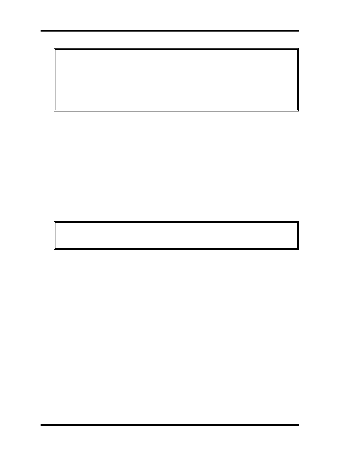
SAMPLE PROCESSING, Auto Mode Procedures
CAUTION: If all the following conditions are met, the sample is assumed blank and
the analysis result will be neither stored nor judged against any
flagging criteria.
3
WBC < 1.00 x 10
RBC < 0.30 x 10
6
/µL
/µL
HGB < 1.0 g/dL
PLT < 20 x 10
3
µL
5 . Output Analysis Results
If automatic output has been set, the analysis results will be sent to the Graphic Printer,
Data Printer, and/or Host Computer.
If automatic output has not been set, the operator must select the data and destination for
the output. See Chapter 4: Result Interpretation/Reports.
6 . Perform Post-Analysis Procedures
Residual blood and reagent can cause detector aperture to clog and protein to build up in
aspiration lines. If the instrument is not to be used for a while, press the [Auto Rinse]
key in the root menu to execute a background check.
NOTE: If the [Auto Rinse] key is not displayed on the LCD, press [More] key
to change the root menu display.
2-36 Sysmex SF-3000 Operator's Manual -- Revised September 1995
Page 75
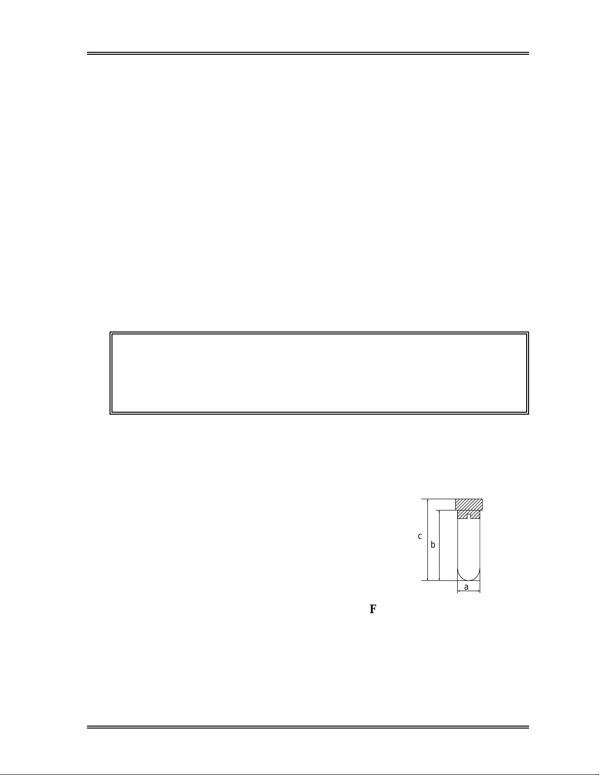
SAMPLE PROCESSING, Manual Closed Mode Procedures
4.4 Manual Closed Mode
Analyses in Manual Closed mode can be performed when the system is in the READY
mode. In this mode, samples are manually mixed, set one at a time into a rack, and
analyzed.
Analysis of the sample is performed in the following steps:
1. Collect and prepare sample
2. Select closed mode
3. Input sample ID number
4. Analyze sample
5. Display analysis results
6. Output analysis results
7. Perform post-analysis procedures
1 . Collect and Prepare Sample
Draw the specified amount of blood (corresponding to the amount of EDTA
anticoagulant).
CAUTION: • Some anticoagulants will alter test results due to their effects on
hemolysis and blood platelet agglutination. Therefore, use K
EDTA, K3 EDTA, or Na2 EDTA as the anticoagulant.
• Samples must be warmed to room temperature for approximately
30 minutes before analysis.
2
The height of the blood sample tube should be 75 mm or shorter. Sample volumes are
shown below.
Required sample volume: 1.0 mL or more
Aspirated sample volume: Approx. 270 µL
Use the type of blood collection tube shown below
for Manual Closed analysis.
Diameter a: 12 - 15 mm
Length b: 75 mm
c
b
Overall length c: 82 mm or less
a
Figure 2-28: Tube Dimensions
Sysmex SF-3000 Operator's Manual -- Revised September 1995 2-37
Page 76

SAMPLE PROCESSING, Manual Closed Mode Procedures
CAUTION: • If VENOJECT® II collection tubes are to be used, contact a
Sysmex service representative for assistance.
• Recapped VENOJECT® II collection tube cannot be used. While
inverting or piercing such a collection tube, the cap may be
removed.
2 . Select Closed Mode
If "Closed Mode" does not appear on the LCD display, follow the procedure below to
select closed mode.
(1) Press the Next No. keypad in the top line of the LCD. The Sample No. Setting
screen will appear.
(2) The selected analysis mode is backlit in light-blue. Press [Closed Mode] to select
Closed mode.
The messages "Not Ready" and "Mode Change" appear in the top line of the LCD.
After the system condition becomes ready for analysis, "Ready" and "Closed
Mode" will be displayed.
Sysmex
Ready
DP:1234567890123
Closed Mode Next No.1234567890123
XM HC GP DP SU
Analysis Mode
Closed Sample Number
1234567890123
Manual Mode
Capillary Mode
Closed Mode
7
4
1
0
C
Sampler
8
5
2
Ð
Q C
9
6
3
ENTER
CANCEL
Figure 2-29: Sample No. Setting Screen (Closed Mode)
2-38 Sysmex SF-3000 Operator's Manual -- Revised September 1995
Page 77
SAMPLE PROCESSING, Manual Closed Mode Procedures
3 . Input Sample ID Number
Using the Sample No. Setting Screen, input the next sample ID number to be analyzed as
described below, if needed.
(1) The next sample number to the previously analyzed sample in Closed mode appears
above the numerical keys. Clear the number by pressing [C] key and input the
sample ID number with the numerical keys, if needed.
NOTE: When the next sample No. is not set, or after the power ON, the next
sample No. is automatically set to No. 1, increasing by 1 for each
succeeding sample (e.g., 1, 2, 3, ...).
(2) Press [ENTER]. The next sample No. is set and the Sample No. Setting screen
will disappear. The input sample No. will be displayed in the Next No. column in
the top line of the LCD.
CAUTION: Do not use zero as the sample ID number. If the ID number is set to
zero, the analysis results will be neither stored nor output. If the
sample I
during sample aspiration to alert the operator.
D number is set to zero, continuous short beeps will sound
NOTE: • The sample ID can include numbers (0-9) and hyphens up to a
maximum of 13 characters.
• Hyphens cannot be placed at the beginning or end of the sample ID
number, nor can two hyphens be placed consecutively.
• A number will not be carried beyond a hyphen. For example, the
number following 2-999 will be 2-000; 1-99-000 will follow 1-99-999.
• The number following 9999999999999 will be 1.
Sysmex SF-3000 Operator's Manual -- Revised September 1995 2-39
Page 78
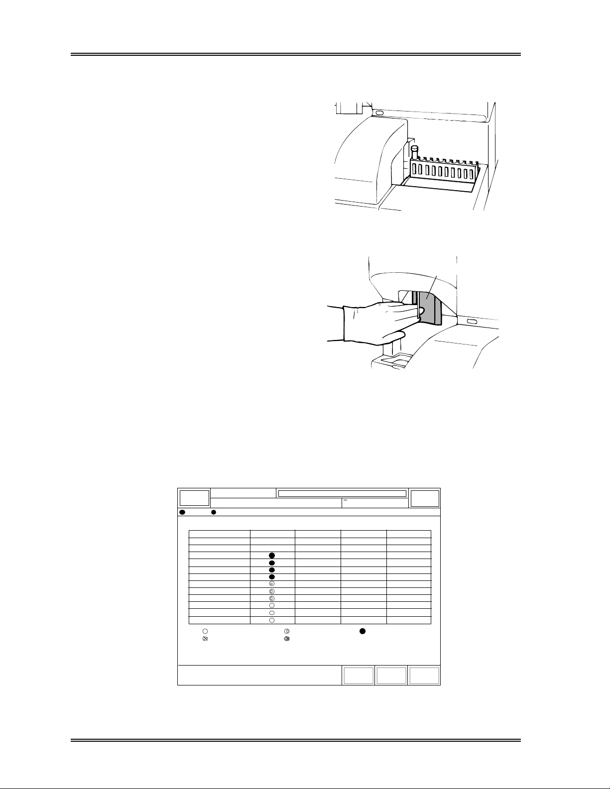
SAMPLE PROCESSING, Manual Closed Mode Procedures
4 . Analyze Sample
(1) Mix the whole blood sample
thoroughly by inverting the tube; then
insert it into the far left position of a
rack (tube position No. 1).
(2) Set the rack in the sampler's right
rack pool.
Figure 2-30: Load Rack on Sampler
(3) Press the Start Switch to start the
analysis.
Start Switch
Figure 2-31: Press the Start Switch
After the rack is automatically moved laterally three times to the piercer hand, sample
aspiration begins. You can check the status of each stage of analysis using the Analysis
Process screen. To see this screen, press [Status] key in the root menu. Switch to "P2.
Analysis Process" using the [→] and [←] keys.
Ready
Sysmex
DP:1234567890123
Status
Sequence
ID No.
Rack
Aspirate
Dilute
RBC Count
WBC/BASO Count
DIFF Count
RBC Analyze
WBC/BASO Analyze
DIFF Analyze
Edit
Store
: Entry
: Interruption
Closed Mode Next No.1234567890123
< Analysis Process >
1
1234567890122
0000-00
Ð
Ð
Ð
Ð
Ð
Ð
Ð
Ð
Ð
Ð
Ð
Ð
Ð
: Run
: Finish Abnormal
XM HC GP DP SU
Ð
Ð
Ð
Ð
Ð
Ð
Ð
Ð
Ð
Ð
Ð
Ð
Ð
: Finish Normal
←
Sampler
Ð
Ð
Ð
Ð
Ð
Ð
Ð
Ð
Ð
Ð
Ð
Ð
Ð
→ Return
Figure 2-32: Analysis Process Screen (Closed Mode)
2-40 Sysmex SF-3000 Operator's Manual -- Revised September 1995
Page 79
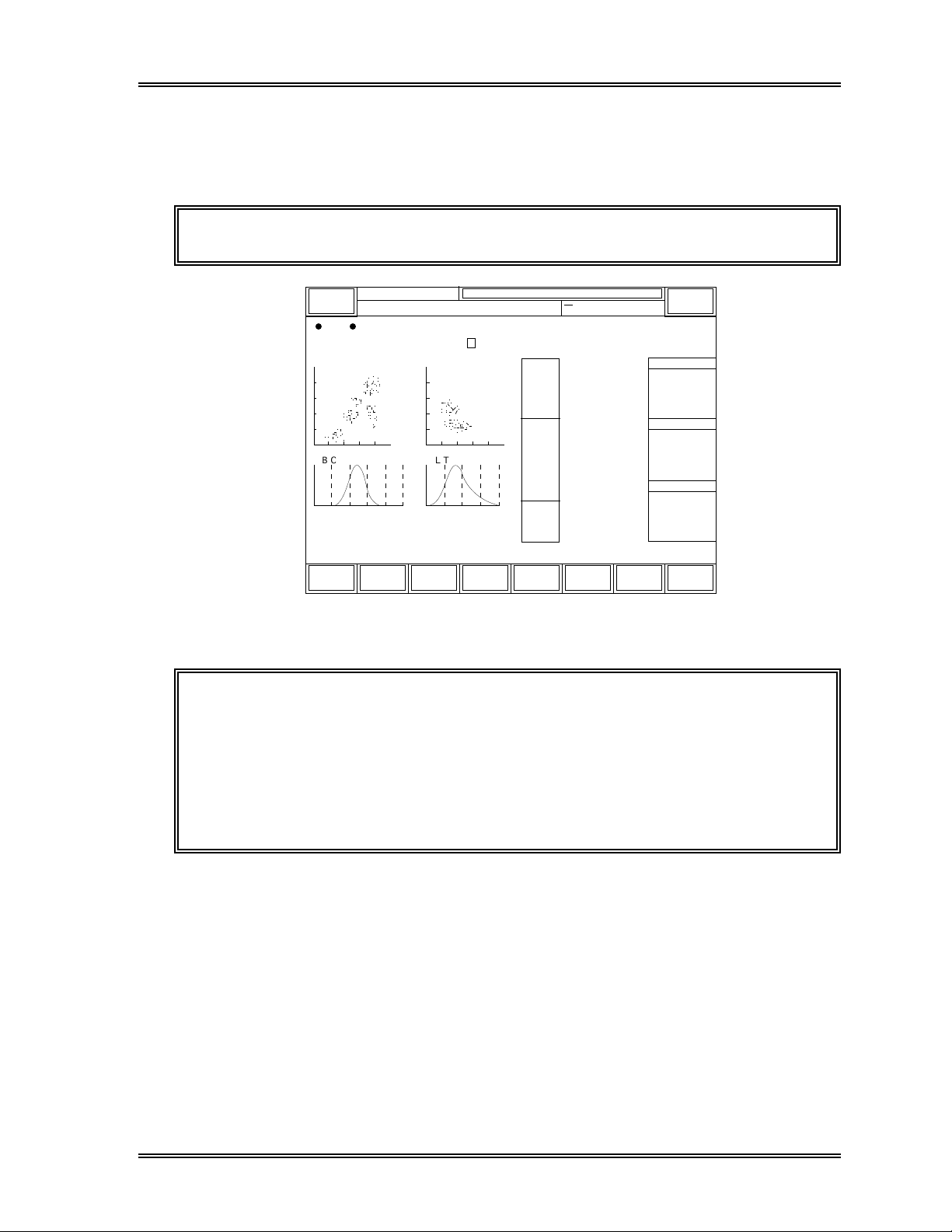
SAMPLE PROCESSING, Manual Closed Mode Procedures
6 . Display Analysis Results
After analysis is complete (approximately 85 seconds after the sample is aspirated), the
results are displayed on the screen.
NOTE: "P" in green back light is added to the left of Sample ID No.
Data
Closed Mode
NO.
P
12345
QC
Next No.1234567890123
XM
HC GP D P SU
GP
Print
7.23
4.62
1.55
0.71
0.18
0.17
4.74
14.1
41.6
87.8
29.7
33.9
46.4
15.7
213
9.8
10.3
24.3
DP
Print
WBC
NEUT
LYMPH
MONO
EO
BASO
RBC
HGB
HCT
MCV
MCH
MCHC
RDW-SD
RDW-CV
PLT
PDW
MPV
P-LCR
15:48 1996/6/30
3
[x10 /uL]
63.9
21.4
9.8
2.5
2.4
6
[x10 /uL]
[g/dL]
[%]
[fL]
[pg]
[g/dL]
[fL]
[%]
3
[x10 /uL]
[fL]
[fL]
[%]
Replace
Reagent
[%]
[%]
[%]
[%]
[%]
Sampler
R:0000-00
WBC Flag
RBC Flag
PLT Flag
Return
Ready
Sysmex
DP:1234567890123
Last
D I F F W B C / B A S O
R B C P L T
250fL 40fL
Status
Work
List
Stored
Figure 2-33: Analysis Results Screen (Closed Mode)
CAUTION: If all the following conditions are met, the sample is assumed blank and
the analysis result will be neither stored nor judged against any
flagging criteria.
WBC < 1.00 x 10
RBC < 0.30 x 10
3
6
/µL
/µL
HGB < 1.0 g/dL
PLT < 20 x 10
3
/µL
7 . Output Analysis Results
If automatic output has been set, the analysis results will be sent to the Graphic Printer,
Data Printer, and/or Host Computer.
If automatic output has not been set, the operator must select the data and destination for
the output. See Chapter 4: Result Interpretation/Reports.
Sysmex SF-3000 Operator's Manual -- Revised September 1995 2-41
Page 80

SAMPLE PROCESSING, Manual Closed Mode Procedures
8 . Perform Post-Analysis Procedures
Residual blood and reagent can cause detector aperture to clog and protein to build up in
aspiration lines. If the instrument is not to be used for a while, press the [Auto Rinse]
key in the root menu to execute an auto rinse and a background check.
NOTE: If the [Auto Rinse] key is not displayed on the LCD, press [More] key
to change the root menu display.
If no further specimens require processing, return the system to Manual mode as follows:
(1) Press the Next No. keypad in the top line of the LCD. The Sample No. Setting
screen will appear.
(2) Press the [Manual Mode] key to select manual analysis mode, and press the
[ENTER] key.
2-42 Sysmex SF-3000 Operator's Manual -- Revised September 1995
Page 81

SAMPLE PROCESSING, Manual CP Mode Procedures
4 .5 Manual CP Mode
Analyses in Manual CP mode can be performed when the system is in the READY mode.
In this mode, samples are manually mixed, set one at a time in the Manual CP unit, and
analyzed.
Analysis of the sample is performed in the following steps:
1. Collect and prepare sample
2. Select closed mode
3. Input sample ID number
4. Analyze sample
5. Display analysis results
6. Output analysis results
7. Perform post-analysis procedures
1 . Collect and Prepare Sample
Draw the specified amount of blood (corresponding to the amount of EDTA
anticoagulant).
CAUTION: • Some anticoagulants will alter test results due to their effects on
hemolysis and blood platelet agglutination. Therefore, use K
EDTA, K3 EDTA, or Na2 EDTA as the anticoagulant.
• Samples must be warmed to room temperature for approximately
30 minutes before analysis.
2
The height of the blood sample tube should be 75 mm or shorter. Sample volumes are
shown below.
Required sample volume: 1.0 mL or more
Aspirated sample volume: Approx. 270 µL
Use the type of blood collection tube shown below
for Manual CP mode analyses.
Diameter a: 12 - 15 mm
Length b: 75 mm
c
b
Overall length c: 82 mm or less
a
Figure 2-34: Tube Dimensions
Sysmex SF-3000 Operator's Manual -- Revised September 1995 2-43
Page 82

SAMPLE PROCESSING, Manual CP Mode Procedures
CAUTION: • If VENOJECT® II collection tubes are to be used, some engineering
change is required. Contact a Sysmex service representative.
• Recapped VENOJECT® II collection tube cannot be used. While
inverting or piercing such a collection tube, the cap may be
removed.
2 . Select Closed Mode
If "Closed Mode" does not appear on the LCD display, follow the procedure below to
select Manual mode.
(1) Press the Next No. keypad in the top line of the LCD. The Sample No. Setting
screen will appear.
(2) The selected analysis mode is backlit in light-blue. Press [Closed Mode] to select
Manual CP mode.
The messages "Not Ready" and "Mode Change" appear in the top line of the LCD.
After the system condition becomes ready for analysis, "Ready" and "Closed
Mode" will be displayed.
Sysmex
Ready
DP:1234567890123
Closed Mode Next No.1234567890123
XM HC GP DP CP
Analysis Mode
Closed Sample Number
1234567890123
Manual Mode
Capillary Mode
Closed Mode
7
4
1
0
C
Sampler
8
5
2
Ð
QC
9
6
3
ENTER
CANCEL
Figure 2-35: Sample No. Setting Screen (Manual CP/Closed Mode)
2-44 Sysmex SF-3000 Operator's Manual -- Revised September 1995
Page 83

SAMPLE PROCESSING, Manual CP Mode Procedures
3 . Input Sample ID Number
Using the Sample No. Setting Screen, input the next sample ID number to be analyzed as
described below, if needed.
(1) The next sample number to the previously analyzed sample in Manual CP mode
appears above the numerical keys. Clear the number by pressing [C] key and input
the sample ID number with the numerical keys, if needed.
NOTE: When the next sample No. is not set, or after the power ON, the next
sample No. is automatically set to No. 1, increasing by 1 for each
succeeding sample (e.g., 1, 2, 3, ...).
(2) Press [ENTER]. The next sample No. is set and the Sample No. Setting screen
will disappear. The input sample No. will be displayed in the Next No. column in
the top line of the LCD.
CAUTION: Do not use zero as the sample ID number. If the ID number is set to
zero, the analysis results will be neither stored nor output. If the
sample I
during sample aspiration to alert the operator.
D number is set to zero, continuous short beeps will sound
NOTE: • The sample ID can include numbers (0-9) and hyphens up to a
maximum of 13 characters.
• Hyphens cannot be placed at the beginning or end of the sample ID
number, nor can two hyphens be placed consecutively.
• A number will not be carried beyond a hyphen. For example, the
number following 2-999 will be 2-000; 1-99-000 will follow 1-99-999.
• The number following 9999999999999 will be 1.
Sysmex SF-3000 Operator's Manual -- Revised September 1995 2-45
Page 84

SAMPLE PROCESSING, Manual CP Mode Procedures
4 . Analyze Sample
(1) Mix the whole blood sample
thoroughly by inverting the tube.
(2) Set the tube in the Manual CP Unit.
(3) Close the Manual CP Unit cover.
(4) Press the Start Switch to start the
analysis.
Figure 2-36: Set Sample in the
Manual CP Unit
After the sample is aspirated, the analysis begins. You can check the status of each stage
of analysis using the Analysis Process screen. To see this screen, press [Status] key in
the root menu. Switch to "P2. Analysis Process" using the [→] and [←] keys.
Ready
Sysmex
DP:1234567890123
STATUS
Sequence
ID No.
Rack
Aspirate
Dilute
RBC Count
WBC/BASO Count
DIFF Count
RBC Analyze
WBC/BASO Analyze
DIFF Analyze
Edit
Store
: Entry
: Interruption
Closed Mode Next No.1234567890123
< Analysis Process >
1
1234567890122
0000-00
Ð
Ð
Ð
Ð
Ð
Ð
Ð
Ð
Ð
Ð
Ð
Ð
Ð
: Run
: Finish Abnormal
XM HC GP DP CP
Ð
Ð
Ð
Ð
Ð
Ð
Ð
Ð
Ð
Ð
Ð
Ð
Ð
: Finish Normal
←
Sampler
Ð
Ð
Ð
Ð
Ð
Ð
Ð
Ð
Ð
Ð
Ð
Ð
Ð
→ Return
Figure 2-37: Analysis Process Screen (Manual CP/Closed Mode)
2-46 Sysmex SF-3000 Operator's Manual -- Revised September 1995
Page 85

SAMPLE PROCESSING, Manual CP Mode Procedures
6 . Display Analysis Results
After analysis is complete (approximately 85 seconds after the sample is aspirated), the
results are displayed on the screen.
NOTE: "P" in green backlight is added to the Sample ID No.
Data
Closed Mode
NO.
P
12345
QC
Ready
Sysmex
DP:1234567890123
Last
D I F F W B C / B A S O
R B C P L T
250fL 40fL
Status
Work
List
Stored
Next No.1234567890123
HC GP D P CP
XM
GP
Print
7.23
4.62
1.55
0.71
0.18
0.17
4.74
14.1
41.6
87.8
29.7
33.9
46.4
15.7
213
9.8
10.3
24.3
DP
Print
WBC
NEUT
LYMPH
MONO
EO
BASO
RBC
HGB
HCT
MCV
MCH
MCHC
RDW-SD
RDW-CV
PLT
PDW
MPV
P-LCR
15:48 1996/6/30
3
[x10 /uL]
63.9
21.4
9.8
2.5
2.4
6
[x10 /uL]
[g/dL]
[%]
[fL]
[pg]
[g/dL]
[fL]
[%]
3
[x10 /uL]
[fL]
[fL]
[%]
Replace
Reagent
[%]
[%]
[%]
[%]
[%]
Sampler
R:0000-00
WBC Flag
RBC Flag
PLT Flag
Return
Figure 2-38: Analysis Results Screen (Manual CP Mode)
CAUTION: If all the following conditions are met, the sample is assumed blank and
the analysis result will be neither stored nor judged against any
flagging criteria.
WBC < 1.00 x 10
RBC < 0.30 x 10
3
6
/µL
/µL
HGB < 1.0 g/dL
PLT < 20 x 10
3
/µL
7 . Output Analysis Results
If automatic output has been set up, the analysis results will be sent to the Graphic
Printer, Data Printer, and/or Host Computer.
If automatic output has not been set up, the operator must select the data and destination
for output. See Chapter 4: Result Interpretation/Reports.
Sysmex SF-3000 Operator's Manual -- Revised September 1995 2-47
Page 86

SAMPLE PROCESSING, Manual CP Mode Procedures
8 . Perform Post-Analysis Procedures
Residual blood and reagent can cause detector aperture to clog and protein to build up in
aspiration lines. If the instrument is not to be used for a while, press the [Auto Rinse]
key in the root menu to execute a background check.
NOTE: If the [Auto Rinse] key is not displayed on the LCD, press [More] key
to change the root menu display.
If no further specimens require processing, return the system to Manual mode as follows:
(1) Press the Next No. keypad in the top line of the LCD. The Sample No. Setting
screen will appear.
(2) Press the [Manual Mode] key to select manual analysis mode, and press the
[ENTER] key.
2-48 Sysmex SF-3000 Operator's Manual -- Revised September 1995
Page 87

SAMPLE PROCESSING
5. SHUTDOWN
When instrument shutdown is performed, the detector chambers and manometers are
cleaned. You should run the instrument through a shutdown cycle at the end of each
day's analyses or at least once every 24 hours if running the instrument continuously.
5.1 Shutdown Procedure
(1) Press the [Shutdown] key from the root menu.
NOTE: If the [Shutdown] key is not displayed on the LCD, press [More] to
change the displayed root menus.
(2) The Shutdown Execute window as shown below will appear. Press [Cancel] key
to cancel the program.
Sysmex
Shutdown
Ready
Shutdown Next No.
XM DP:
It will take approx. 10 minutes.
Set CELLCLEAN to the pipette
and press Start Switch.
Cancel
HC GP D P SU
Sampler
Figure 2-39: Shutdown Execute Window
WARNING! CELLCLEAN (or 5% filtered sodium hypochlorite) is a strong alkaline
solution. Avoid contact with it. If you get it on your skin or clothing,
immediately wash it off with excess water.
Sysmex SF-3000 Operator's Manual -- Revised October 1995 2-49
Page 88

SAMPLE PROCESSING, Shutdown
(3) Position the CELLCLEAN [or 5%
filtered sodium hypochlorite (bleach)]
into the manual aspiration pipette as
Start Switch
shown in Figure 2-40; then press the
START switch. Do not remove the
CELLCLEAN while the READY LED is
blinking as CELLCLEAN is being
aspirated.
(4) After the READY LED turns off and the
CELLCLEAN
alarm beeps three times, remove the
CELLCLEAN.
(5) The shutdown sequence will start.
Figure 2-40: Introduce CELLCLEAN
During shutdown sequence, "Shutdown
in Progress." is displayed on the LCD.
(6) After the shutdown sequence is completed, a continuous beep will sound and the
Shutdown Complete screen will appear.
Ready LED
Sysmex
Shutdown
Ready
Shutdown Next No.
Turn OFF power to shut down.
Press Restart to continue analyses.
Restart
X
M DP:
HC GP D P SU
Sampler
Figure 2-41: Shutdown Complete Screen
(7) If you are going to shutdown the instrument, turn the Main Unit power OFF. Turn
the printers off, if attached.
NOTE: If you are going to continue to operate, perform a background check by
pressing the [Restart] key displayed on the LCD.
2-50 Sysmex SF-3000 Operator's Manual -- Revised October 1995
Page 89

SAMPLE PROCESSING
6 . TIMER MODE
When timer mode is used, the Pneumatic Unit power automatically turns OFF if the Main
Unit does not detect any operation of the Start Switch or the keys on the LCD to cycle the
instrument within a preset amount of time. "Not Ready", "PU Off" and "PRESS
START SWITCH" messages are displayed in the top lines of LCD. To set, see Chapter
11: System Setup.
6.1 Restarting the Pneumatic Unit
To restart the Pneumatic Unit, press the Start Switch.
Start Switch
Figure 2-42: Press the Start Switch
CAUTION: If the Main Unit is not in Ready status, the Timer Mode does not
function and the Pneumatic Unit power will not turn OFF.
Sysmex SF-3000 Operator's Manual -- Revised October 1995 2-51
Page 90

CHAPTER 3 WORK LIST
1. INTRODUCTION ...............................................................3-1
1.1 Order Inquiry Method.....................................................3-1
2. EXECUTING A WORK LIST PROGRAM..................................3-2
2.1 Work List Display .........................................................3-2
2.2 Data Entry ..................................................................3-3
3. DOWNLOAD LIST..............................................................3-6
3.1 From Host Computer (HC) ..............................................3-6
3.2 From Floppy Disk (FD) ..................................................3-8
4. DELETE......................................................................... 3-10
4.1 All Data ...................................................................3-10
4.2 Marked Data..............................................................3-11
4.3 Current Data.............................................................. 3-12
5. GP OUTPUT ................................................................... 3-13
6. BACKUP ....................................................................... 3-14
Revised July 1996
Page 91
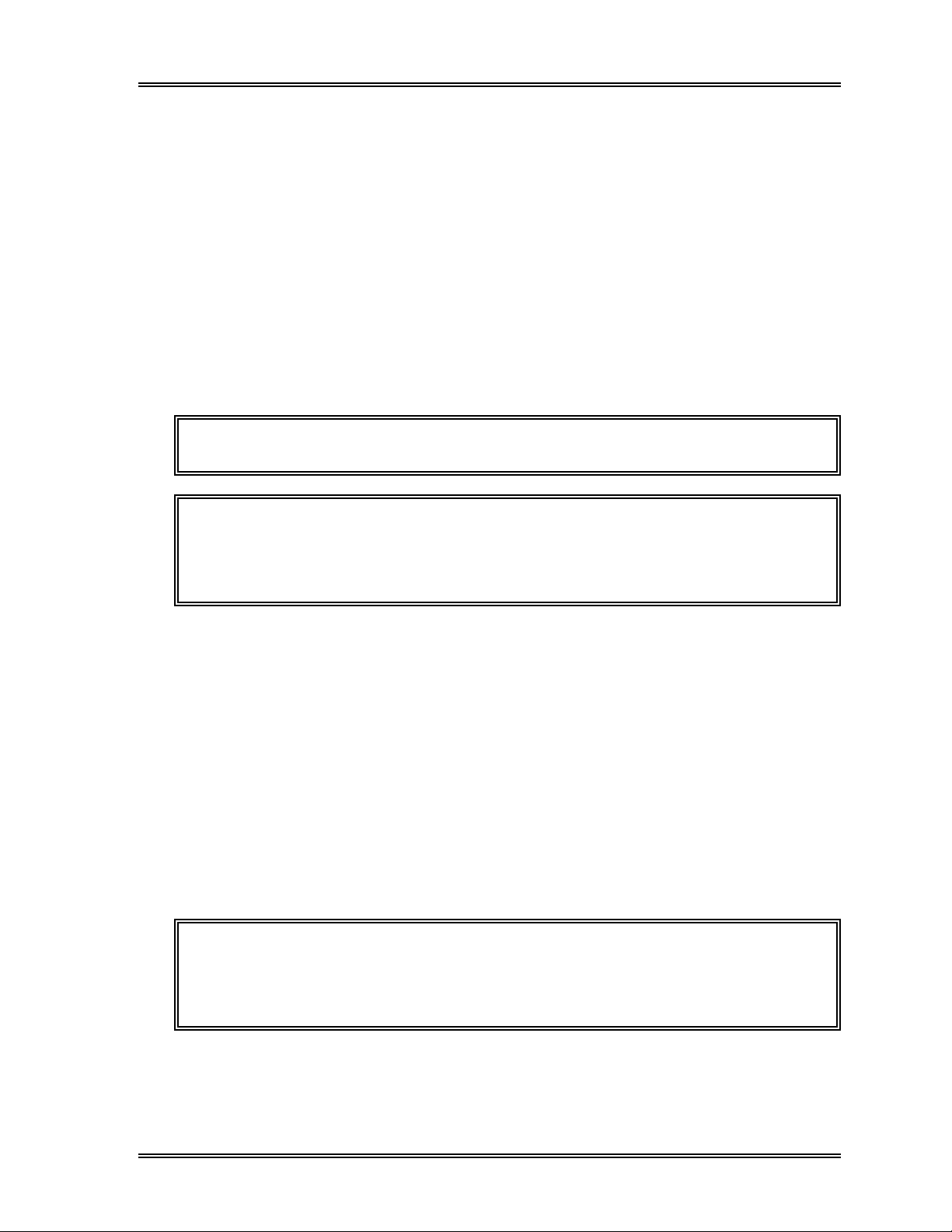
1. INTRODUCTION
The SF-3000 registers ordering analysis information which enables the user to specify
the samples to be analyzed.
Order information on 50 samples can be input by LCD touch panel or by transmission
from the host computer. In addition, they can be registered by downloading from a
floppy disk. This chapter describes registering and processing of analysis information.
Order information includes the followings:
• Rack No.
• Tube Position
• Sample No.
• Analysis Order
NOTE: The order information is applicable for Auto Mode analysis only.
NOTE: When the Work List is set as "Not Used", order inquiry of the Work List
will not be performed. To perform order inquiry of the Work List, set
the Work List to "Used", using the setting program. Refer to
11, Section 6.9: Work List
for information.
WORK LIST
Chapter
1.1 Order Inquiry Method
The analysis operation on a sample will be performed according to analysis information
ordered as below:
1. Perform inquiry of the Work List prior to analysis. Analyze the sample according
to the order request, if registered.
2. When the analysis order is not registered in Work List for that sample, the SF-3000
analyzes the sample.
Analysis operation is performed by each order inquiry made by Sample ID No. or
Rack-Tube Position No. according to the system setting. Refer to Chapter 11,
Section 6.9 Work List for the setting.
NOTE: If the data processing system model SF-DPS is installed with the
SF-3000, the real-time order inquiry of the host computer can be
performed. Contact your Sysmex sales representatives for
information.
Sysmex SF-3000 Operator's Manual -- Revised July 1996 3-1
Sysmex SF-3000 Operator's Manual --- Revised September 1995
Page 92

WORK LIST
2 . EXECUTING A WORK LIST PROGRAM
Press [Work List] keypad in the Root Menu. The Work List as shown in Figure 3-1
appears. The analysis information is input using this display.
When the Work List screen appears, the second menu also appears in the bottom line.
The second menu provides the following processing modes: "Down Load", "Output" and
"Delete". These modes can be selected through the LCD touch panel. Refer to the
following sections for the procedures.
Ready
Sysmex
DP:1234567890123
Work
List
RACK-TUBE
0001-01
0001-02
0001-03
0001-04
0001-05
0001-06
0001-07
0001-08
0001-09
0001-10
0002-01
0002-02
0002-03
0002-04
0002-05 123-456-789-25
Down
Load
SAMPLE No. ORDER
123-456-789-10
123-456-789-11
123-456-789-12
123-456-789-13
123-456-789-14
123-456-789-15
123-456-789-16
123-456-789-17
123-456-789-18
123-456-789-20
123-456-789-21
123-456-789-22
123-456-789-23
123-456-789-24
Output Delete
Manual Mode Next No.1234567890123
Prev
↑
↓
Next
Mark
XM HC GP DP SU
Sample
No.
Rack No.
0002-05
78
456
123
0
C
Figure 3-1: Work List Display
2.1 Work List Display
The Work List display contains the following information:
Sampler
[0/15]
OrderRack Repeat
9
-
ENTER
CANCEL
Displayed Items
• RACK-TUBE
Displays the rack number (1 - 9999) and the tube position number indicates the
location of the blood sample tube in the rack (1 - 10).
• SAMPLE No.
Displays the sample ID number (up to 13 digits).
• ORDER
Displays the analysis order inquiry and the status of the sample analysis in progress.
Blank : Indicates that the sample is not to be analyzed.
Circle ( ) : Indicates that the sample is to be analyzed but has not
been analyzed.
Double Circle ( ) : Indicates that analysis is complete.
Cross (X) : Indicates that an analysis error occurred, preventing
the completion of sample analysis.
• [#/##]
Number of marked samples/Number of registered samples in the list is indicated
above [Repeat] keypad.
3-2 Sysmex SF-3000 Operator's Manual --- Revised July 1996
Page 93
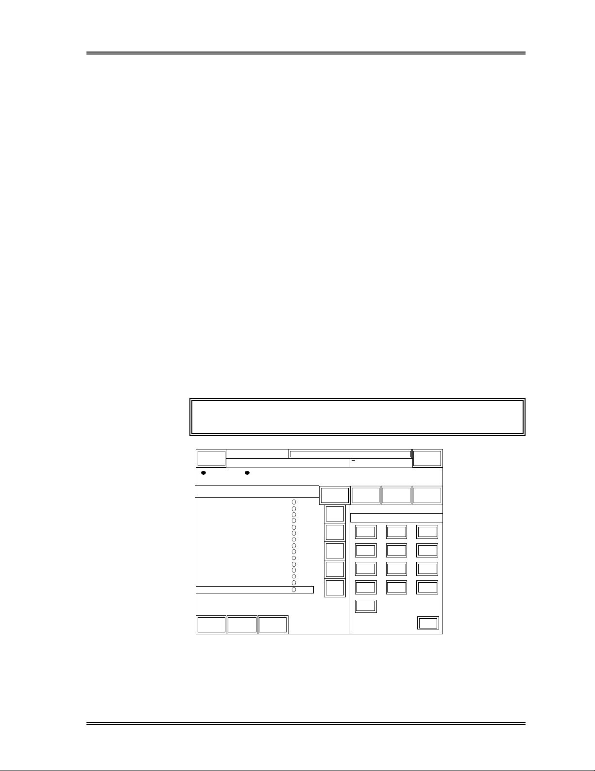
WORK LIST
Key Operation
[ ↑ ] key : Cursor (displayed in reverse video) moves up one sample. When the
cursor is placed on the top line, the page is scrolled down.
[ ↓ ] key : Cursor moves down one sample. When the cursor is placed on the
bottom line of the LCD, the page is scrolled up.
When the cursor is placed on the bottom line of the list, this key has
repeat function. Refer to the description about [Repeat] key in the
following section.
[Prev] key : Cursor moves up one page (20 samples).
[Next] key : Cursor moves down one page (20 samples).
[Mark] key : Marks data. Refer to Section 4.2: Marked Data in this chapter.
2.2 Data Entry
The Work List display contains the following function keys to enter the order
information. Order information can be input on up to 50 samples.
[Rack] key : When this key is pressed, "Rack No." is displayed above the numeric
keys. The rack number (4 digits) and the tube position number (1 - 10)
can be input with the numeric keys. Place a hyphen between the rack
number and the tube position number. See Figure 3-2.
NOTE: Rack-Tube Position No. is a set number.
Ready
Sysmex
DP:1234567890123
Work
List
RACK-TUBE
0001-01
0001-02
0001-03
0001-04
0001-05
0001-06
0001-07
0001-08
0001-09
0001-10
0002-01
0002-02
0002-03
0002-04
0002-05 123-456-789-25
Down
Load
SAMPLE No. ORDER
123-456-789-10
123-456-789-11
123-456-789-12
123-456-789-13
123-456-789-14
123-456-789-15
123-456-789-16
123-456-789-17
123-456-789-18
123-456-789-20
123-456-789-21
123-456-789-22
123-456-789-23
123-456-789-24
Output Delete
Manual Mode Next No.1234567890123
Prev
↑
↓
Next
Mark
XM HC GP DP SU
Sample
No.
Rack No.
0002-05
OrderRack Repeat
78
456
123
0
C
Sampler
[0/15]
9
-
ENTER
CANCEL
Figure 3-2: Rack - Tube Position No. Input Screen
Sysmex SF-3000 Operator's Manual -- Revised July 1996 3-3
Page 94
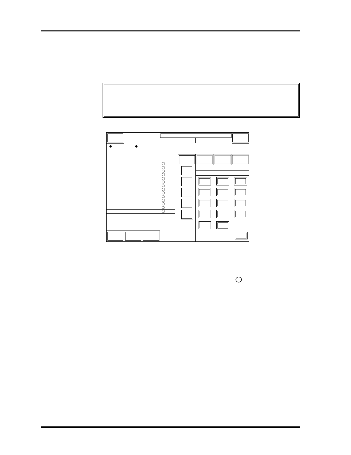
WORK LIST, Data Entry
[Sample No.] key : When this key is pressed, "Sample No." is displayed above the
numeric keys as shown in Figure 3-3. Sample numbers up to 13
numerical digits and hyphens can be input.
A hyphen cannot be placed at the beginning or end of the number
and two or more hyphens cannot be placed consecutively.
NOTE: If the Sample No. column is left blank with no number
entry, a sequential number for Auto mode analysis will
be automatically assigned for the sample.
Sysmex
Work
RACK-TUBE
0001-01
0001-02
0001-03
0001-04
0001-05
0001-06
0001-07
0001-08
0001-09
0001-10
0002-01
0002-02
0002-03
0002-04
Down
Load
Ready
DP:1234567890123
List
SAMPLE No. ORDER
123-456-789-10
123-456-789-11
123-456-789-12
123-456-789-13
123-456-789-14
123-456-789-15
123-456-789-16
123-456-789-17
123-456-789-18
123-456-789-19
123-456-789-20
123-456-789-21
123-456-789-22
123-456-789-23
Output Delete
Manual Mode Next No.1234567890123
Prev
↑
↓
Next
Mark
XM HC GP DP SU
Sample
No.
Sample No.
123-456-789-23
OrderRack Repeat
78
456
123
0
C
–
QC
Figure 3-3: Sample No. Input Screen
[Order] key : Analysis order is set by pressing this key.
Pressing this key places or removes a circle ( ) from the sample on
which the cursor (displayed in reverse video) is placed. Place a
circle to analyze the sample, or remove the circle for not to analyze
the sample.
Sampler
[0/14]
9
ENTER
CANCEL
3-4 Sysmex SF-3000 Operator's Manual -- Revised July 1996
Page 95
WORK LIST, Data Entry
[Repeat] key : When this key is pressed, "Repeat" is displayed above the numeric
keys.
Enter the number of samples to enter the order information and press
[Enter].
The Rack-Tube and Sample ID No. which are incremented by one to
those of the previous sample will be assigned. The analysis order
information appears the same as the previous sample. See the
example below.
Example)
When the cursor is on a sample with order information;
Rack-Tube: "0001-01", Sample No.: "123-456", Order " "
Pressing [Repeat], [3], then [ENTER] keypads will assign the
following three samples as below:
Rack-Tube: "0001-02", Sample No.: "123-457", Order " "
Rack-Tube: "0001-03", Sample No.: "123-458", Order " "
Rack-Tube: "0001-04", Sample No.: "123-459", Order " "
NOTE: Since the order information can be input on up to 50
samples, a number between 1 and 49 can be accepted
after pressing [Repeat] key.
NOTE: When the cursor is placed on the bottom of the list, [ ↓ ]
key functions as repeat key when pressed, which will
assign the Rack-Tube Position No. and the Sample No.
incremented by one to those of the previous sample.
NOTE: A number will be carried beyond a hyphen. For
example, the Rack-Tube No. following 0001-10 will be
0002-01, 0001-01 will follow 9999-10.
[0] - [9], [–] : Inputs number or a hyphen.
[QC] : Press this key to set the QC samples by registering the QC File No.
in which the L-J QC analysis results are stored as control data. For
example, press [QC] and [1] keys to specify the QC File No. 01.
[ENTER] : Sets the input values.
[C] : Used as a backspace key to delete one character.
Sysmex SF-3000 Operator's Manual -- Revised July 1996 3-5
Sysmex SF-3000 Operator's Manual -- Revised September 1995
Page 96

WORK LIST
3. DOWNLOAD LIST
With this program you can download order information from a host computer (HC) or
floppy disk (FD) to the SF-3000.
3.1 From Host Computer (HC)
You can inquire about order information from the Host Computer using the rack number.
(1) Press [Down Load] keypad. The Down Load window as shown in Figure 3-4 will
appear.
Sysmex
Work
RACK-TUBE
Down
Load
Ready
DP:1234567890123
List
SAMPLE
Output Delete
Manual Mode Next No.1234567890123
Down Load
H o s t
F D
XM HC GP DP SU
Order Repeat
Cancel
Sampler
[0/0]
Return
Figure 3-4: Down Load Window
(2) Press the [Host] keypad. The HC Down Load screen as shown in Figure 3-5 will
be displayed.
Sysmex
Work
Ready
DP:1234567890123
List
Manual Mode Next No.1234567890123
XM HC GP DP SU
< HC Down Load >
Sampler
[0/0]
R a c k N o . 1
1.
2. R a c k N o . 0
3. R a c k N o .
4. R a c k N o .
5. R a c k N o .
Cancel
Down
Load
Output Delete
0
0
0
O K
Rack No.
↑
↓
78
456
123
0
C
0
9
ENTER
CANCEL
Figure 3-5: HC Down Load Screen
3-6 Sysmex SF-3000 Operator's Manual -- Revised July 1996
Page 97

WORK LIST, Down Load, From HC
(3) Input the rack number with numeric keypads and press [Enter]. The rack number
will be registered, and the cursor will move to the next rack number. Move the
cursor by using the [↑] and [↓] keys.
(4) Pressing [Cancel] cancels the down loading and returns to the Work List display.
When all rack numbers have been input, press the [OK] key. The order
information transmission from the host computer will start.
If rack numbers are not set, the program ends and the instrument returns to the
Work List Display screen.
Ready
Sysmex
DP:1234567890123
Work
List
1.
2. R a c k N o . 0
3. R a c k N o .
4. R a c k N o .
5. R a c k N o .
Down
Load
Output Delete
R a c k N o . 1
Manual Mode Next No.1234567890123
< HC Down Load >
XM HC GP DP SU
↑
0
0
0
O KCancel
↓
Download from HC
[0/10]
Stop
Sampler
[0/0]
Quit
Figure 3-6: HC Down Loading Message Window
Sysmex SF-3000 Operator's Manual -- Revised July 1996 3-7
Page 98

WORK LIST, Down Load
3.2 From Floppy Disk (FD)
This program reads order information from a floppy disk, re-utilizing previously backed
up order information.
(1) Press [Down Load] keypad. The Down Load window as shown in Figure 3-7 will
appear.
Sysmex
Work
RACK-TUBE
Down
Load
Ready
DP:1234567890123
List
SAMPLE
Output Delete
Manual Mode Next No.1234567890123
Down Load
H o s t
F D
XM HC GP DP SU
Order Repeat
Cancel
Sampler
[0/0]
Return
Figure 3-7: Down Load Window
(2) Press the [FD] keypad. The FD Down Load screen as shown in Figure 3-8 will be
displayed.
Sysmex
Work
RACK-TUBE
Ready
DP:1234567890123
List
SAMPLE NO . ORDER
Manual Mode Next No.1234567890123
Prev
XM HC GP DP SU
Sample
No.
OrderRack Repeat
Sampler
[0/0]
< Download from FD >
Insert FD and press OK key.
Cancel O K
Mark
Down
Load
Output Delete
Return
Figure 3-8: FD Down Load Screen
3-8 Sysmex SF-3000 Operator's Manual -- Revised July 1996
Page 99

WORK LIST, Down Load, From FD
(3) Insert the floppy disk containing the order
information file into the floppy disk drive.
(4) Press [OK] key to read the order information
file.
Press [Cancel] key to stop the program and
return to the List Display screen.
Figure 3-9: Insert Floppy Disk
(Main Unit - Right Side)
When a disk is not inserted when pressing [OK] or the disk is unreadable, "FD Read
Error" will appear. Press [OK] key to close the window and retry the FD down load
using a correct floppy disk, if needed.
< FD Read Error >
Press OK key.
OK
Figure 3-10: FD Read Error Window
Sysmex SF-3000 Operator's Manual -- Revised July 1996 3-9
Sysmex SF-3000 Operator's Manual -- Revised September 1995
Page 100
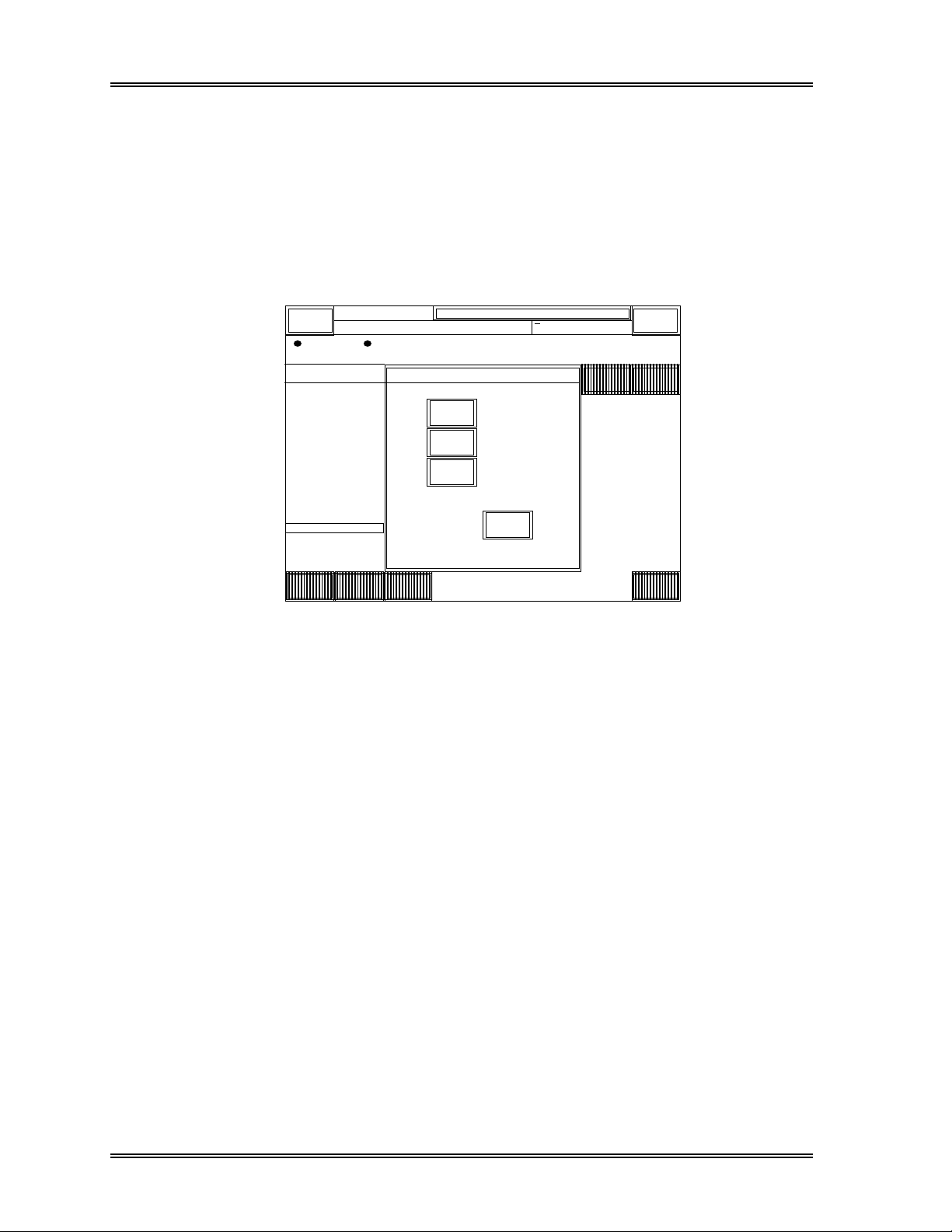
WORK LIST
4 . DELETE
You can delete specified order information registered in memory. If you select this
menu, the "Delete" submenu appears, enabling you to choose "Current", "Marked" or
"All" data.
To delete order information:
(1) Press [Delete] keypad. The Delete window appears as shown in Figure 3-11.
Sysmex
Work
RACK-TUBE
0001-01
0001-02
0001-03
0001-04
0001-05
0001-06
0001-07
0001-08
0001-09
0001-10
0002-01
0002-02
0002-03
0002-04
0002-05
Down
Load
Ready
DP:1234567890123
List
SAMPLE
123-456
123-456
123-456
123-456
123-456
123-456
123-456
123-456
123-456
123-456
123-456
123-456
123-456
123-456
123-456
Output Delete
Manual Mode Next No.1234567890123
XM HC GP DP SU
Delete
Current
Marked
A l l
Cancel
Sampler
[0/15]
Order Repeat
Return
Figure 3-11: Delete Window
(2) Press the desired keypad to specify the data to be deleted.
(3) Press [OK] key to delete the data. Refer to the following sections for the
procedure.
4.1 All Data
Use this program to delete all the order information.
(1) Display the Work List on the screen.
(2) Press [Delete] key to display the Delete window.
(3) Press [All] key. The Delete Confirmation window will appear as shown in Figure
3-12 below.
3-10 Sysmex SF-3000 Operator's Manual -- Revised July 1996
 Loading...